

Samsung RSG5D SERIES, RSG5F SERIES, RSG25 SERIES Service Manual
SBS TYPE
BASIC : RSH1D
MODEL NAME : RSG5D**
RSG5F**
RSG5K**
RSG5B**
MODEL CODE : RSG5DUMH1/XEU
RSG5FURS1/XEF
RSG257AARS/XAA
RSG5BLAW/1XSC
RSG5VLWJ1/XSC
RSG25**
RSG5V**
REFRIGERATOR
REFRIGERATOR
CONTENTS
- For the latest parts information, Please access to our service web site
(• North America : http;//service.samsungportal.com • Latin America : http;//latin.samsungportal.com
• CIS : http;//cis.samsungportal.com • Europe : http;//europe.samsungportal.com
• China : http;//china.samsungportal.com • Asia : http;//asia.samsungportal.com
• Mideast & Africa : http;//mea.samsungportal.com)
RSG5D*RSG5V* RSG5B* RSG5F/K*
1. PRECAUTIONS
(SAFETY WARNINGS)....................................................5
2. PRODUCT SPECIFICATIONS.........................................8
3. DISASSEMBLY & REASSEMBLY.................................17
4. TROUBLE SHOOTING..................................................47
5. PCB DIAGRAM..............................................................88
6. WIRING DIAGRAM........................................................92
7. SCHEMATIC DIAGRAM &
BLOCK DIAGRAM ........................................................97
8. REFERENCE INFORMATION .....................................106


3
IMPORTANT SAFETY NOTICE
The service guide is for service men with adequate backgrounds of
electrical, electronic, and mechanical experience. Any attempt to repair
a major appliance may result in personal injury and property damage.
The manufacturer or dealer cannot be responsible for the interpretation
of this information.
SAMSUNG ELECTRONICS AMERICA, INC.
Technical Service Guide
Copyright ⓒ2008
All rights reserved. This service guide may not be reproduced in whole or in
part in any form without written permission from the SAMSUNG ELECTRONICS
Company.
WARNING

4
Contents
1. PRECAUTION(SAFETY WARNINGS .....................................................................5
2. PRODUCT SPECIFICATIONS ................................................................................8
3. DISASSEMBLY & REASSEMBLY .........................................................................17
4. TROUBLE SHOOTING..........................................................................................45
5. PCB DIAGRAM .....................................................................................................88
6. WIRING DIAGRAM ...............................................................................................92
7. SCHEMATIC DIAGRAM & BLOCK DIAGRAM......................................................97
8. REFERENCE INFORMATION.............................................................................106

5
1. PRECAUTIONS(SAFETY WARNINGS)
● Unplug the appliance before servicing or replacing electrical Parts.
● Use rated electronic Control equipment.
Make sure to check out ModeL name, Rated voltage, Rated current, Operation Temp, etc.
● Upon repair, make sure that harnesses are not to be water-penetrated and are bundled tight.
Should not be detached by a certain amount of external force.
● Upon repair, completely remove dust or other foreign substances from housing, harness,
connector, etc.
To prevent fire by tracking, short, etc.
● Check out whether water has penetrated into the electronic Control system.
If there is any kind of trace, take necessary measures such as related component change,
insulation tapping, etc.
● After repair, check out the assembled state of parts.
It should be the same as the previous state.
● Check out the surrounding conditions.
Change the location, if the fridge is located at humid, wet places or the installed state is
unstable.
● In order to reduce the risk of electric shock the appliance must be properly grounded.
● Do not allow consumers to overload a certain outlet.
● Check out whether the power cord or the outlet is broken, squeezed, chopped off or heat-
deformed.
Repair or replace the defective power cord/outlet immediately.
Make sure the power cord is not punctuated or stomped down.
● Do not allow consumers to keep food frayed or place bottles in the Freezer Room.
● Do not allow consumers to repair the fridge by themselves.
● Do not allow consumers to keep things except for food.
Pharmaceutical, Chemical substances : These are not possible to be fine-Controlled with a
consumer fridge.
Flammable material (alcohol, benzene, ether, LPG, etc) : possibility of explosion.
6
SAFETY WARNINGS
Read all instructions before repairing the product and keep to the instructions
in order to prevent danger or property damage.
CAUTION/WARNING SYMBOLS DISPLAYED
SYMBOLS
Indicates that a
danger of death
or serious injury
exists.
Indicates that a risk
of personal injury
or material damage
exists.
means “Prohibition”.
means “Do not disassemble”.
means “No contact”.
means ”The things to
be followed”.
means “Earth to prevent Electric
shock”.
means “Power cord should be
unplugged from the consent”
Unplug the appliance before
servicing or replacing electrical
parts.
●
It may cause electric shock.
Warning
Warning & Caution
Caution
Earth
Unplug
Use the rated components
on the replacement.
●
Check the correct model, rated
voltage, rated current, operating
temperature and so on.
On repair, make sure that the
wires such as harness are
bundled tightly.
●
Bundle tightly wires in order not to be
detached by the external force and then not
to be wetted.
Check if there is any trace
indicating the permeation
of water.
●
If there is that kind of trace, change
the related components or do the
necessary treatment
such as taping
using the
insulating tape.
After repair, check the
assembled state of components.
●
It must be in the same assembled state
when compared with the state before
disassembly.
On repair, remove completely dust
or other things of housing parts,
harness parts, and check parts.
●
Cleaning may prevent the possible fire by
tracking or short.
Rated
components

SAFETY WARNINGS
❈
Please ler users know following warnings & cautions in detail.
Do not allow users to put bottles or
kinds of glass in the freezer.
●
Freezing of the contents may inflict a wound.
Do not allow users to store narrow
and lengthy bottles or foods in a
small multi-purpose room.
●
It may hurt you when refrigerator door is
opened and closed resulting in falling stuff
down.
Do not allow users to store
pharmaceutical products, scientific
materials, etc., in the refrigerator.
●
The products which temperature control
should not be stored in the refrigerator.
Do not allow users to store
articles on the product.
●
Opening or closing the door may cause
things to fall down, with may inflict a
wound.
Prohibition
Prohibition
Prohibition
Prohibition
Warning & Caution
Do not allow users to
disassemble, repair or alter.
●
It may cause fire or abnormal
operation which leads to injury.
Do not
disassemble
Do not allow users to insert the
power plugs for many products
at the same time.
●
May cause abnormal generation of
heat or fire.
Prohibition
Do not allow users to bend the
power cord with excessive force
or do not have the power cord
pressed by heavy article.
●
May cause fire.
Do not allow users to install the
refrigerator in the wet place or
the place which water splashes.
●
Deterioration of insulation of electric
parts may cause electric shock or fire.
In order to reduce the risk of
electric shock the appliance
must be properly grounded.
Earth
When installing, servicing or cleaning behind
the refrigerator, be sure to pull the unit straight
out and push back in straight after finishing.
CAUTION
7

8
2. PRODUCT SPECIFICATIONS
2-1) Characteristics .....................................................................................................9
2-2) Model Specification ............................................................................................10
2-3-1) Basic Specification..........................................................................................12
2-3-2) Electric Parts Specification .............................................................................12
2-4) Dimensions (mm) ...............................................................................................15
2-5) Optional Material Specification ..........................................................................16

9
2-1) Charcteristics
PRODUCT SPECIFICATIONS
●●
Comparison with basic
Tower LED Lighting
Changed Part
CABI LAMP
DOOR
Description Basic Current
●●
New Option
Adapted Part
CABI
Automoisture
Drawer
(RSG5B*ONLY)
Description Image
DOOR
Clear View
Icemaker
More freezer storage space
DOOR
Tilt Can
Carry
Constant slant angle for
easy access of cans & bottles
To maintain the optimal humidity in
the crisper, the fine-mesh holes in the
polymer control the flow of moisture
through hole according to the humidity
in the bin.
DISPENSER
New Design Dispenser
HANDLE
Built_In Easy Handle
(RSG5BL**, RSG5V**)
10
2-2) Model Specification
PRODUCT SPECIFICATIONS
NOTE
This operation instruction covers various models.
The characteristics of your appliance may differ slightly from those described in this manual.
- Key features of your new refrigerator
Your Samsung Side-By-Side Refrigerator comes equipped with many
space-saving, innovative storage and energy-efficient features.
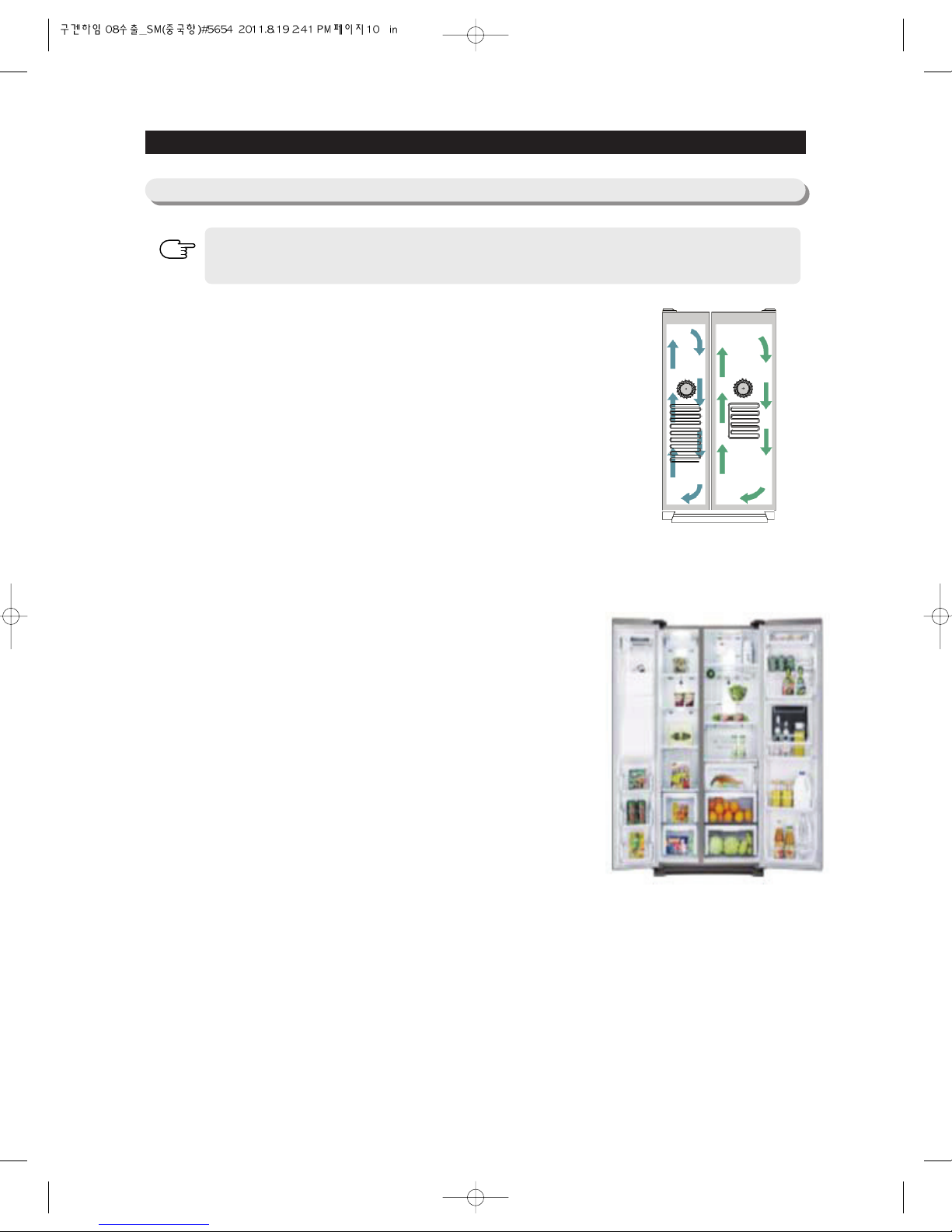
• Twin Cooling Plus
TM
Twin CoolingTM‚ system uses two evaporators to independently control
temperature of the refrigerator and freezer compartments maintaining proper
humidity levels and preventing odor transfers between compartments.
• Multi Airflow
Provides even cooling throughout the refrigerator to maintain optimal
temperatures to keep food fresh.
• LED Tower Lighting
See everything in a new light with LED tower lighting.
• CoolSelect Zone
TM
(Optional)
With this state of the art feature, you can select Quick Cool, Thaw or Select
buttons to quickly chill, thaw and cool items just in the CoolSelect drawer.
• Clear View Icemaker
The Icemaker is located in the freezer door, this ensures that all the shelf
space can be fully utilized. Ice cubes are quickly produced and the clear ice
bucket lets you easily see the amount of ice cubes produced.
• Premium Design Ice & Water Dispenser
Quick and easy access to filtered water and cubed/crushed ice at your
fingertips with the external dispenser.
11
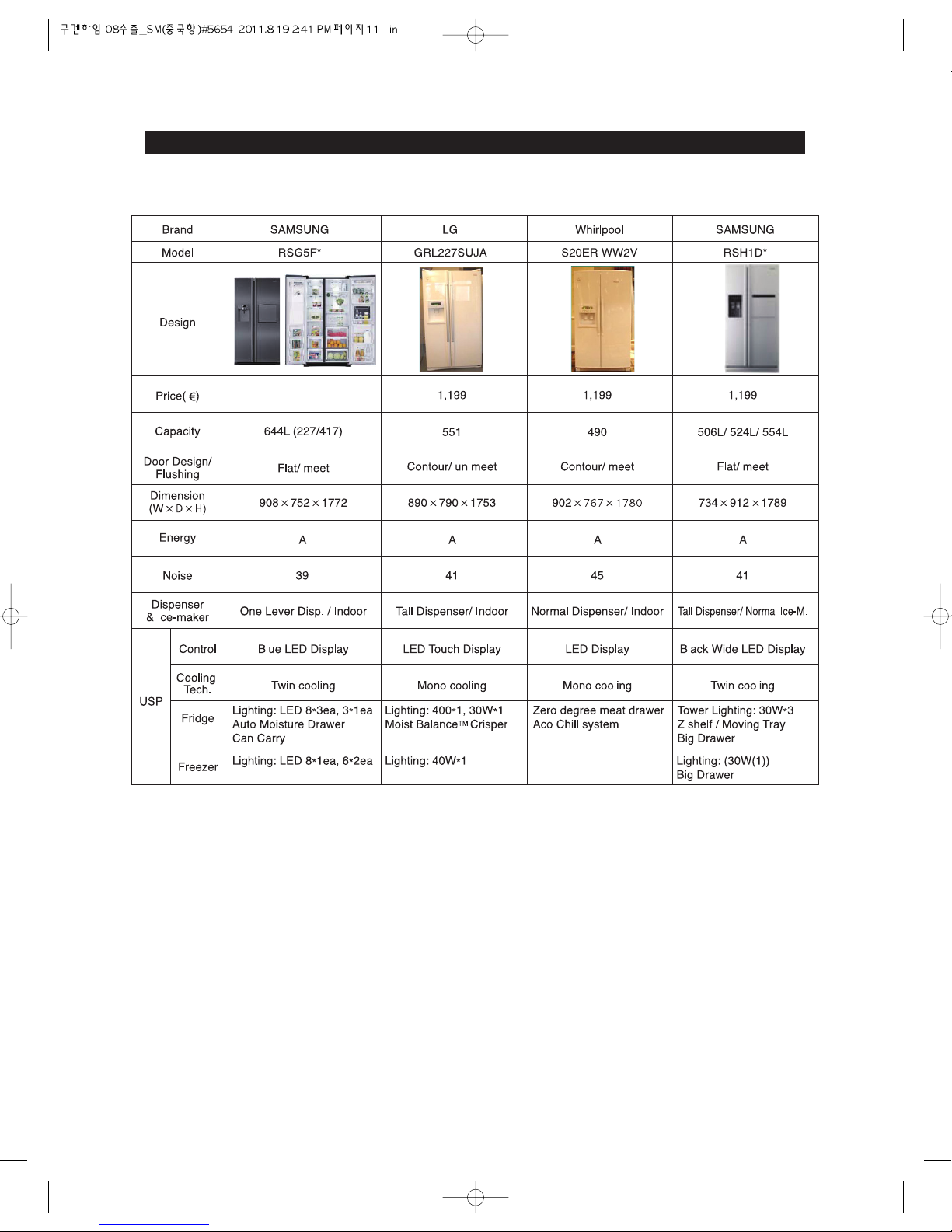
PRODUCT SPECIFICATIONS
- Comparison with competitor

2-3-1) Basic Specification
PRODUCT SPECIFICATIONS
2-3-2) Electric Parts Specification
12
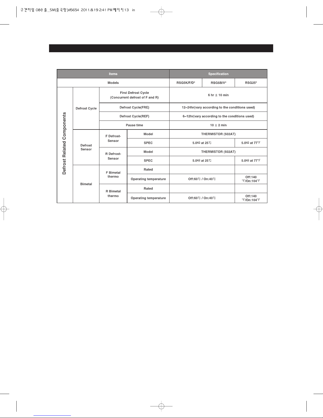
PRODUCT SPECIFICATIONS
13
AC 250V 3A AC 125V 6A
AC 125V 6A
AC 250V 3A

PRODUCT SPECIFICATIONS
14
Conducting at R Defrost
Conducting at
Water Tank Heater
Cool Select Zone Heater
Cord 230V 3W
Cord 230V 6W
Sheath 140W
Cord 120V 5.4W
LED (16EA)
LED (10EA)
LED (12EA)
LED (10EA)
LED
LED
Sheath 115V 200W
127V 200W
Sheath 230V 218W
Sheath 230V 218W

15
PRODUCT SPECIFICATIONS
2-4) Dimensions (mm/inch)
RSG5K/F/DU**(mm)
RSG5BL**(mm)
RSG5V**
RSG257AA**(inch)
PRODUCT SIZE
A
BCDEF
687
50
10.4
697.4
737
427 553 1773
27 7/16 1 31/32 30 16 13/16 21 25/32 70

PRODUCT SPECIFICATIONS
2-5) Optional Material Specification
16
Photograph Part Name Part Code
Quantity
Remark
FILTER
WATER-ASSY
DA29-00003B 1
RSG5K/F/D*
RSG257*
ASSY-INSTALL
FILTER
ASSY-PACKING
VALVE
DA97-05926B
DA99-00240W
1(5500mm)
1
RSG5K/F/D*
RSG257*

17
3. DISASSEMBLY & REASSEMBLY
3-1) PRECAUTION....................................................................................................18
3-2) Home Bar ...........................................................................................................19
3-3) Interior(Fridge) ...................................................................................................20
3-4) Evaporator Cover(Fridge)...................................................................................22
3-5) Multi Duct(Fridge)...............................................................................................23
3-6) Display ...............................................................................................................24
3-7) Coolselect Zone .................................................................................................26
3-8) Dispenser ...........................................................................................................28
3-9) Interior(Freezer) .................................................................................................29
3-10) Evaporator Cover(Freezer)...............................................................................30
3-11) Ice & Multi Duct(Freezer) .................................................................................30
3-12) Door .................................................................................................................31
3-13) Evaporator........................................................................................................34
3-14) PBA Compartment ...........................................................................................35
3-15) Water Valve ......................................................................................................37
3-16) Machine Compartment.....................................................................................38
3-17) Fan ASSY(Freezer & Fridge) ...........................................................................40
3-18) Handle..............................................................................................................41
3-19) Water Pipe .......................................................................................................43
3-20) Icemaker Compartment ...................................................................................44
3-21) Defrosting Heater Fridge & Freezer .................................................................45
3-22) Compressor......................................................................................................46

18
DISASSEMBLY & REASSEMBLY
• Unplug the appliance before servicing or replacing electrical parts.
• Remove any foreign matter or dust from the power plug pins.
- Otherwise there is a risk of fire.
• Do not use a cord that shows cracks or abrasion damage along its length or at either end.
• Do not plug several appliances into the same multiple power board. The refrigerator should always be
plugged into its own individual electrical which has a voltage rating that matched the rating plate.
- This provides the best performance and also prevents overloading house wiring circuits, which could
cause a fire hazard from overheated wires.
• Do not install the refrigerator in a damp place or place where it may come in contact with water.
- Deteriorated insulation of electrical parts may cause an electric shock or fire.
• In order to reduce the risk of electric shock the appliance must be properly grounded.
• Do not put bottles or glass containers in the freezer.
- When the contents freeze, the glass may break and cause personal injury.
• Do not store volatile or flammable substances in the refrigerator.
- The storage of benzene, thinner, alcohol, ether, LP gas and other such products may cause
explosions.
- NEED TOOL
3-1) PRECAUTION
ITEM HOW TO USE PICTURES
Phillips Head Driver
Use for assembling and
disassembling of screw
Flat Head Driver
Use for assembling and disassembling
of Beverage Station, Dispenser, Display,
Cover Lamp etc...
Hex Wrench ØØ2mm
Use for assembling and
disassembling of Handle
Socket Wrench
ØØ
10m
Magnet
Use for assembling and
disassembling of Door Hinge
Use for checking of the F/R Fan

3-2) Home Bar
19
DISASSEMBLY & REASSEMBLY
Disassemble the Cap Damper by
inserting a flat-blade screwdriver into the
slot and lifting it up.
Remove a screw and a washer.
Disassemble the Cover-Latch by
inserting a flat-blade screwdriver into the
slot and pulling it gently.
① Remove the shaft.
② Disassemble the Oil-Damper by lifting
it up.
Remove the Home-bar by pulling it out
while inserting a flat-blade screwdriver
into the hole and pulling out the shaft
as shown.
PART NAME DESCRIPTION
Home bar
Door
Oil Damper
Latch
FIGURE

20
3-3) Interior-Fridge
DISASSEMBLY & REASSEMBLY
Disconnect the housing connector(Reed
S/W) by gently pulling them apart.
Remove the 2 screws and replace the
Latch.
PART NAME DESCRIPTION
Latch
FIGURE
Pull the shelf out to the hole point.
And then remove it by turning and lifting it
up.
Remove all Drawers before
disassembling the cover.
Pull the cover out to the hole point.
And then remove it by turning and lifting it
up.
Remove the Water Tank from the
Evaporator cover by unscrewing the
screws.
PART NAME DESCRIPTION
Shelf
Drawer
Cover
Water Tank
FIGURE
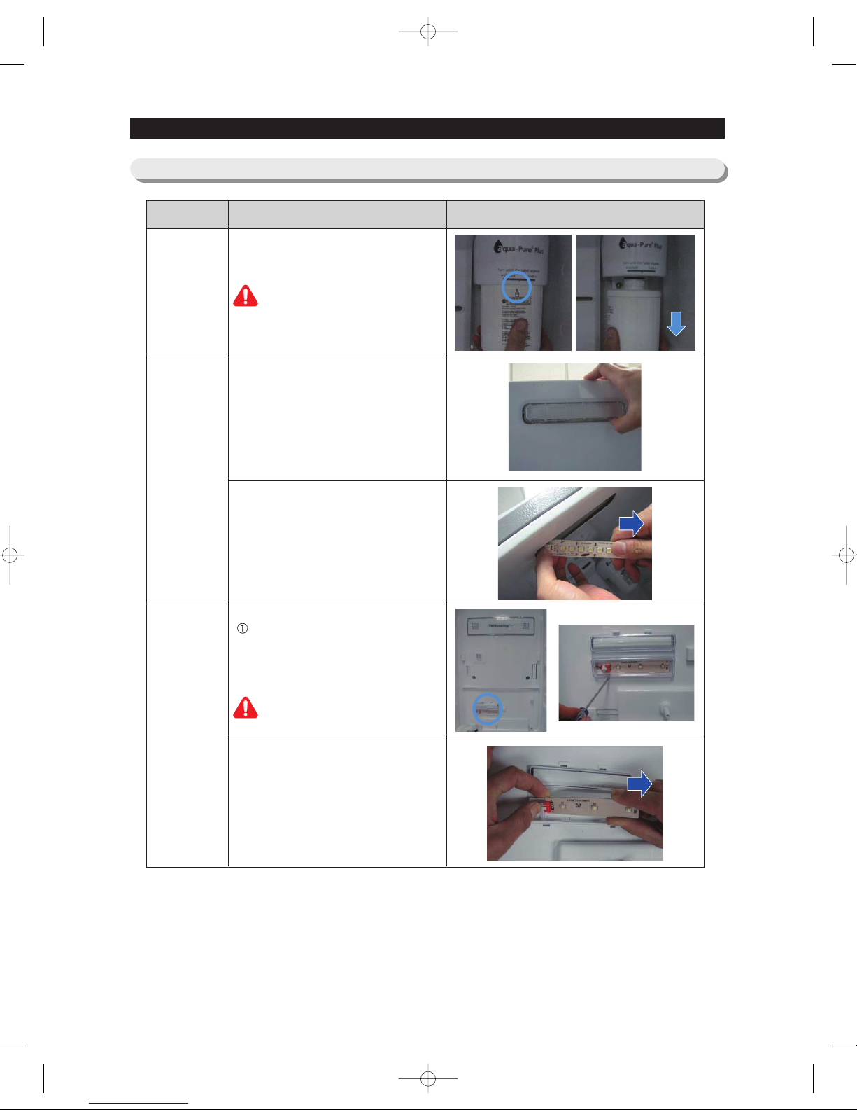
Turn the water filter 1/2 turn counterclockwise and pull it down.
To install the filter, slowly turn the water
filter clockwise to align with the printing
mark on the cover, locking the filter in
position.
Disassemble the Cover-Lamp by pulling
the hook.
Disengage the housing connector.
Disengage the housing connector.
Insert a flat-blade screwdriver into the
slot and disassemble the Lamp
Cover(Low) by lifting the screwdriver
up gently.
Be careful not to damage the lamp.
PART NAME DESCRIPTION
Water Filter
LED
(Front)
LED
Lamp
(Low)
FIGURE
21
DISASSEMBLY & REASSEMBLY

22
DISASSEMBLY & REASSEMBLY
3-4) Evaporator Cover-Fridge
Remove the 7 screws by turning
counter-clockwise.
Pull the Evaporator Cover in the
direction of the front.
Disengage the housing connectors of
the Evaporator Cover.
PART NAME DESCRIPTION
Evap. Cover
(Fridge)
FIGURE
23
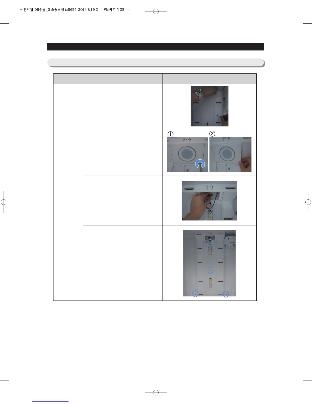
DISASSEMBLY & REASSEMBLY
3-5) Multi Duct-Fridge
PART NAME DESCRIPTION
Multi Duct
(Fridge)
FIGURE
① Insert a flat-blade screwdriver into the
slot and turn the screwdriver gently.
Be careful not to damage the lamp.
② Pull out the Lamp Cover.
① Insert a flat-blade screwdriver into the
slot as shown in the picture and turn
the screwdriver gently.
② Pull out the Cap Sensor.
Disengage the housing connector.
Remove the 4 screws and disassemble
the Multi Duct.
24
DISASSEMBLY & REASSEMBLY
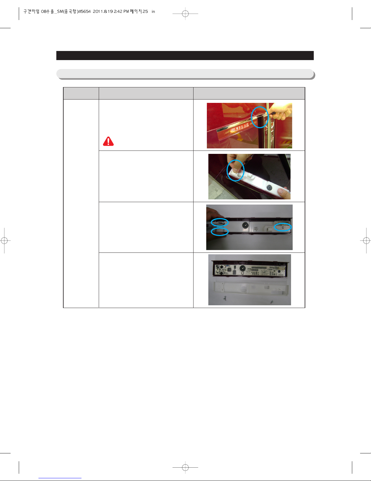
3-6) Display
Unscrew by turning a screw counter
clockwise at the bottom of the Display.
① Insert a flat-blade screwdriver into a
slot as shown and turn it gently.
② Pull out the Dispenser Cover.
Disengage the housing connectors of
Display Cover.
Remove the 3 screws of the Display
Cover.
Disassemble the Lamp by pulling the
hook.
PART NAME DESCRIPTION
Display
(RSG5K/F/D
*, RSG257*)
FIGURE
25
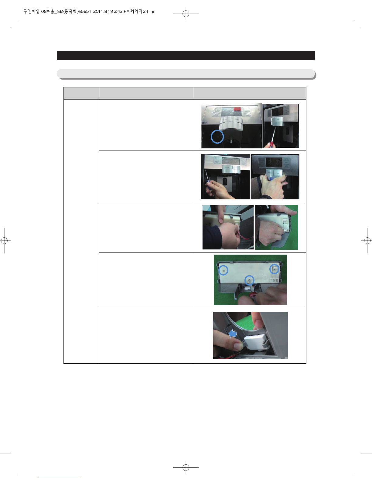
DISASSEMBLY & REASSEMBLY
Insert a flat-blade screwdriver into a side
as shown and pull the Display out.
Disengage the housing connectors of
Display.
Remove the 3 screws on the back of the
Display.
Replace the PBA Panel after
disassembling the PBA Rear.
PART NAME DESCRIPTION
Display
(RSG5B/V*)
FIGURE
Be careful not to scratch.

26
DISASSEMBLY & REASSEMBLY
3-7) Coolselect Zone
After disassembling the top shelf of the
Coolselect Zone, remove 2 screws as
shown.
Pull the Coolselect Zone out to the
front side and then disengage the
connector.
Disassemble the Cover LED at the
bottom of Coolselect Zone with small
flat-blade screwdriver.
Disassemble photosynthesis LED with
pressing the hook and then disengage
the connector.
PART NAME DESCRIPTION
Coolselect
Zone
FIGURE

27
DISASSEMBLY & REASSEMBLY
Remove 2 screws at the back.
Disassemble the hook at the both
side with flat-blade screwdriver.
Lift the back side and then disassemble
the Cover as shown.
Disengage the connector.
PART NAME DESCRIPTION
Coolselect
Zone Heater
FIGURE
Disassemble the earth wire with wrench
as shown.
Remove 6 screws fixing Heater Plate
at the both side.

28
DISASSEMBLY & REASSEMBLY
3-8) Dispenser
① Disassemble the hose by pulling.
② Disengage the housing connectors.
Remove the 2 screws of the Ice Route
Case.
Disassemble the Ice Route Case Assy
by pulling the hooks inside as shown.
Insert a flat-blade screwdriver into the
slot as shown and pull out.
Push out the rib like picture and then
pull out the Micro Switch.
PART NAME DESCRIPTION
Ice Route
Dispenser
Micro S/W
FIGURE

2929
DISASSEMBLY & REASSEMBLY
3-9) Interior-Freezer
① Pull the shelf out to the hole point.
② Remove it by turning and lifting it up.
Remove all Drawers before
disassembling the cover.
Pull the cover out to the hole point.
And then remove it by turning and lifting
it up.
① Insert a flat-blade screwdriver into the
slot as shown in the picture and turn
the screwdriver gently.
② Pull out the Cap Sensor.
Disengage the housing connector of the
Sensor(the left one of the two).
Take off the seal carefully for reuse.
Disassemble and replace the Sensor.
PART NAME DESCRIPTION
Shelf
Drawer
Cover
Sensor
(Freezer)
FIGURE
30
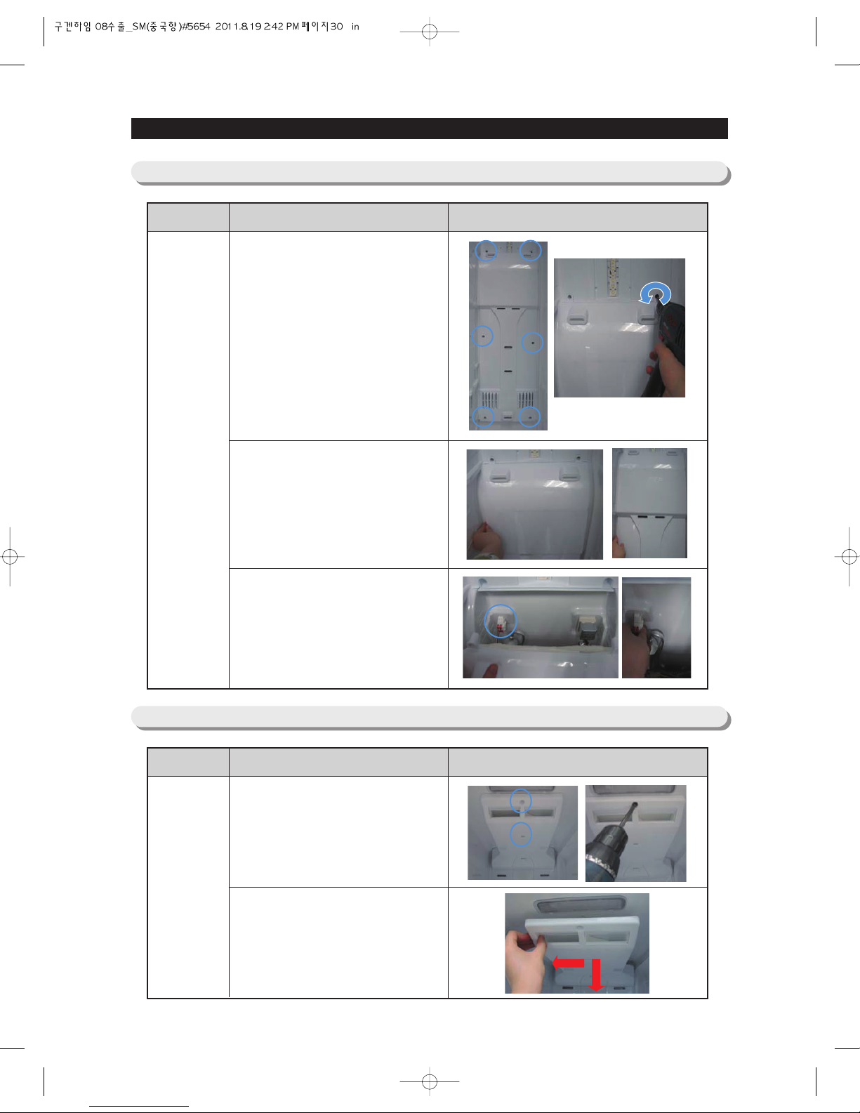
DISASSEMBLY & REASSEMBLY
3-10) Evaporator Cover-Freezer
Remove the 6 screws by turning
counter-clockwise.
Pull the Evaporator Cover in the
direction of the front.
Disassemble the Evaporator Cover by
disengaging the housing connector.
PART NAME DESCRIPTION
Evap.
Cover
(Freezer)
FIGURE
3-11) Ice Duct & Multi Duct-Freezer
Remove the 2 screws at the top.
Pull the Ice Duct out gently to the front
after pushing middle of the Ice duct to
the left with pushing to the back.
PART NAME DESCRIPTION
Ice Duct
FIGURE
 Loading...