

Samsung RS267LBBP, RS263BBWP, RS265LBWP, RS263BBSH, RS267LBSH Service Manual
...
REFRIGERATOR
SIDE BY SIDE
BASIC : RS265BBWP, RS267LBBP
MODEL NAME : RS263BBWP RS265LBBP
RS263BBBB RS265LBWP
RS263BBSH RS267LBSH
RS264ABBP RS264ABRS
RS264ABSH RS264ABWP
RS267BBBB RS269LBRS
RS267BBSH RS267BBRS
MODEL CODE : RS263/264/265/267/269**/XAA
REFRIGERATOR PRODUCT FEATURE
●●
NEW DIGITAL DISPLAY(LED)
●●
TOWER LIGHTING
●●
CONTOUR DOOR/HIDDEN HINGE
●●
CLEAN LOOK DRAWER
●●
TWIN COOLING
●●
HUMAN TOUCH HANDLE
RS26**
For the latest information, Please access to our service web site (http://itself.sec.samsung.co.kr)
IMPORTANT SAFETY NOTICE
The service guide is for service men with adequate backgrounds of
electrical, electronic, and mechanical experience. Any attempt to repair
a major appliance may result in personal injury and property damage.
The manufacturer or dealer cannot be responsible for the interpretation
of this information.
SAMSUNG ELECTRONICS AMERICA, INC.
Technical Service Guide
Copyright ⓒ2006
All rights reserved. This service guide may not be reproduced in whole or in
part in any form without written permission from the SAMSUNG ELECTRONICS
Company.
WARNING

3
Contents
1. PRECAUTIONS (SAFETY WARNINGS) ······················· 4
2. PRODUCT SPECIFICATIONS
·····························
8
3. OPERATING INSTRUCTIONS & INSTALLATION
··················
20
4. ALIGNMENT AND ADJUSTMENTS
··························
28
5. DISASSEMBLY AND REASSEMBLY
·························
36
6. TROUBLESHOOTING
·································
49
7. EXPLODED VIEW & PARTS LIST
···························
62
8. BLOCK DIAGRAM
····································
79
9. WIRING DIAGRAM
···································
80
10. PCB DIAGRAM
·····································
82
11. CIRCUIT DIAGRAM ·································· 84
12. CIRCUIT DESCRIPTIONS
······························
85
13. SAFETY INSTRUCTIONS ON SERVICE
······················
94
14. REFERENCE INFORMATION
····························
100

4
1. PRECAUTIONS(SAFETY WARNINGS)
●
Pull the power plug out before for the change or repair of electric parts.
→
Be careful the electric shock.
●
When exchanging the parts, use the correct parts.
→
Check the model name, rating voltage, rating current, running
temperature symbols.
●
When troubleshooting, connect firmly the types of harness.
→
Make not to be separated when some power is imposed.
●
Check the traces of water infiltration at the electric parts.
→
If there is a trace of water infiltration, exchange or tape the parts.
●
Check the assemble status of parts after troubleshooting.
→
It should be done indiscriminately as before the repair.
●
Check the use circumstance of refrigerator.
→
If the refrigerator is installed at the place that is damp or wet, or
status of installation is unstable, change the installation place.
●
Do earth in case of need.
→
Particularly, Be sure to earth when there is a risk of an electric
leakage by humidity or wetness.
●
Do not use multi plugs in a plug socket at the same time.
Check if the power cord and socket is damaged, pressed, squeezed,
or fired.
→
If the plug or plug socket is damaged, repair or exchange that
immediately.
●
Do not repair the refrigerator by user himself.
●
Do not store other materials except the foods.
→
Drugs or scientific materials : difficult to keep precise temperature.
→
The inflammables(alcohol, benzene, ether, LP gas, butane gas etc.):
have risk of explosion.
5
1. PRECAUTIONS(SAFETY WARNINGS)
Read all instructions before repairing the product and follow the instructions
in order to prevent danger or property damage.
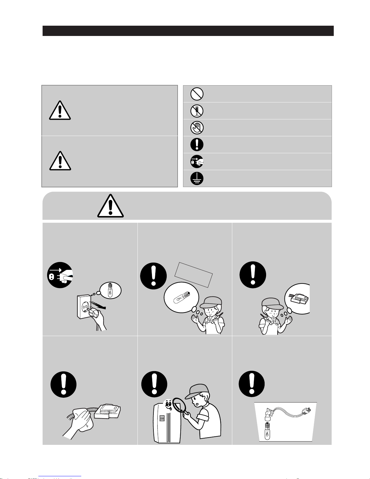
CAUTION/WARNING SYMBOLS DISPLAYED
SYMBOLS
Indicates that a
danger of death
or serious injury
exists.
Indicates that a risk
of personal injury
or material damage
exists.
means “Prohibition”.
means “Do not disassemble”.
means “No contact”.
means ”The things to
be followed”.
means “Earth to prevent Electric
shock”.
means “Power cord should be
unplugged from the consent”
Pull the power plug out to
exchange the interior lamp
of the refrigerator.
●
It may cause electric shock.
Warning
Warning & Caution
Caution
Unplug
Use the rated components
on the replacement.
●
Check the correct model, rated
voltage, rated current, operating
temperature and so on.
On repair, make sure that the
wires such as harness are
bundled tightly.
●
Bundle tightly wires in order not to be
detached by the external force and then not
to be wetted.
Check if there is any trace
indicating the permeation
of water.
●
If there is that kind of trace, change
the related components or do the
necessary treatment
such as taping
using the
insulating tape.
After repair, check the
assembled state of components.
●
It must be in the same assembled state
when compared with the state before
disassembly.
On repair, remove completely dust
or other things of housing parts,
harness parts, and check parts.
●
Cleaning may prevent the possible fire by
tracking or short.
Rated
components
6
1. PRECAUTIONS(SAFETY WARNINGS)
❈
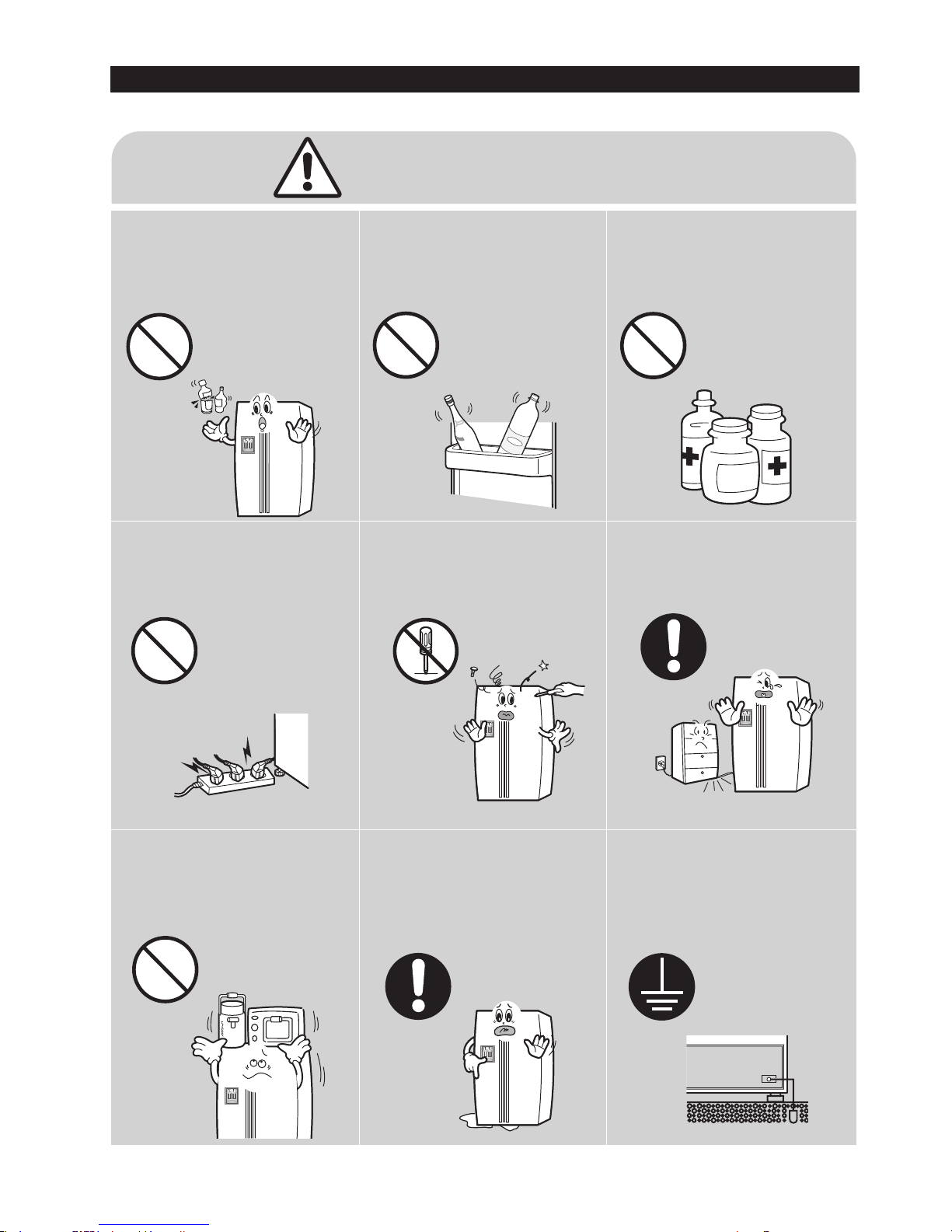
Please let users know following warnings & cautions in detail.
Do not allow users to put bottles or
kinds of glass in the freezer.
●
Freezing of the contents may inflict a wound.
Do not allow users to store narrow
and lengthy bottles or foods in a
small multi-purpose room.
●
It may hurt you when refrigerator door is
opened and closed resulting in falling stuff
down.
Do not allow users to store
pharmaceutical products, scientific
materials, etc., in the refrigerator.
●
The products which temperature control
should not be stored in the refrigerator.
Do not allow users to store
articles on the product.
●
Opening or closing the door may cause
things to fall down, with may inflict a
wound.
Prohibition
Prohibition
Prohibition
Prohibition
Warning & Caution
Do not allow users to
disassemble, repair or alter.
●
It may cause fire or abnormal
operation which leads to injury.
Do not
disassemble
Do not allow users to insert the
power plugs for many products
at the same time.
●
May cause abnormal generation of
heat or fire.
Prohibition
Do not allow users to bend the
power cord with excessive force
or do not have the power cord
pressed by heavy article.
●
May cause fire.
Do not allow users to install the
refrigerator in the wet place or
the place where water splashes.
●
Deterioration of insulation of electric
parts may cause electric shock or fire.
Make sure of the earth.
●
If earthing is not done, it will cause
breakdown and electric shock.
Earth

7
2. PRODUCT SPECIFICATIONS
2-1) Introduction of main function ·····························8
2-2)
Specifications
·······································9
2-3)
Interior Views
······································ 10
2-4)
Model Specification &Comparison Chart
······················· 11
2-5)
Model Specification &Comparison Chart
······················· 12
2-6)
Dimensions of Refrigerator (Inches)
·························· 15
2-7)
Optional Material Specification
····························· 16
2-8)
Refrigerant Route in Refrigeration cycle
························· 17
2-9)
Cooling Air Circulation
·································· 18
8
2. PRODUCT SPECIFICATIONS
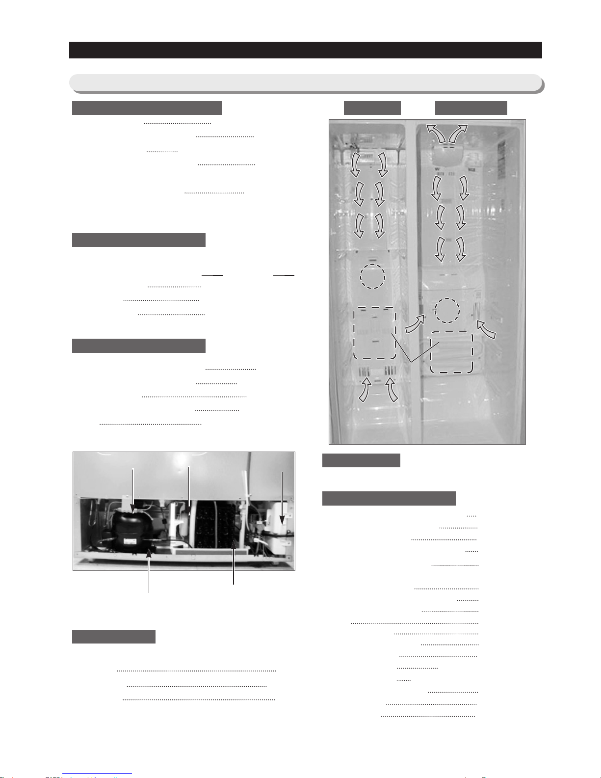
●●
A newly developed SAMSUNG side by side refrigerator in 2006 has the following
characteristics.
Twin Cooling System
●●
The refrigerator and the freezer have two evaporators. Given this
independent system, the freezer and the refrigerator are cooled
individually as required and are, therefore, more efficient. Food
odor from the refrigerator does not affect food in the freezer due
to separate air flow circulation.
Multi-Flow System
●●
Cool air circulates through multiple vents on every shelf level.
This provides even distribution of cooling inside cabinets to keep
your food fresh longer.
Xtra Space
TM
●●
Vertical room next to the ice maker in the freezer provides space
for pizza etc.
Door Alarm
●●
Beep sound reminds you the door is open.
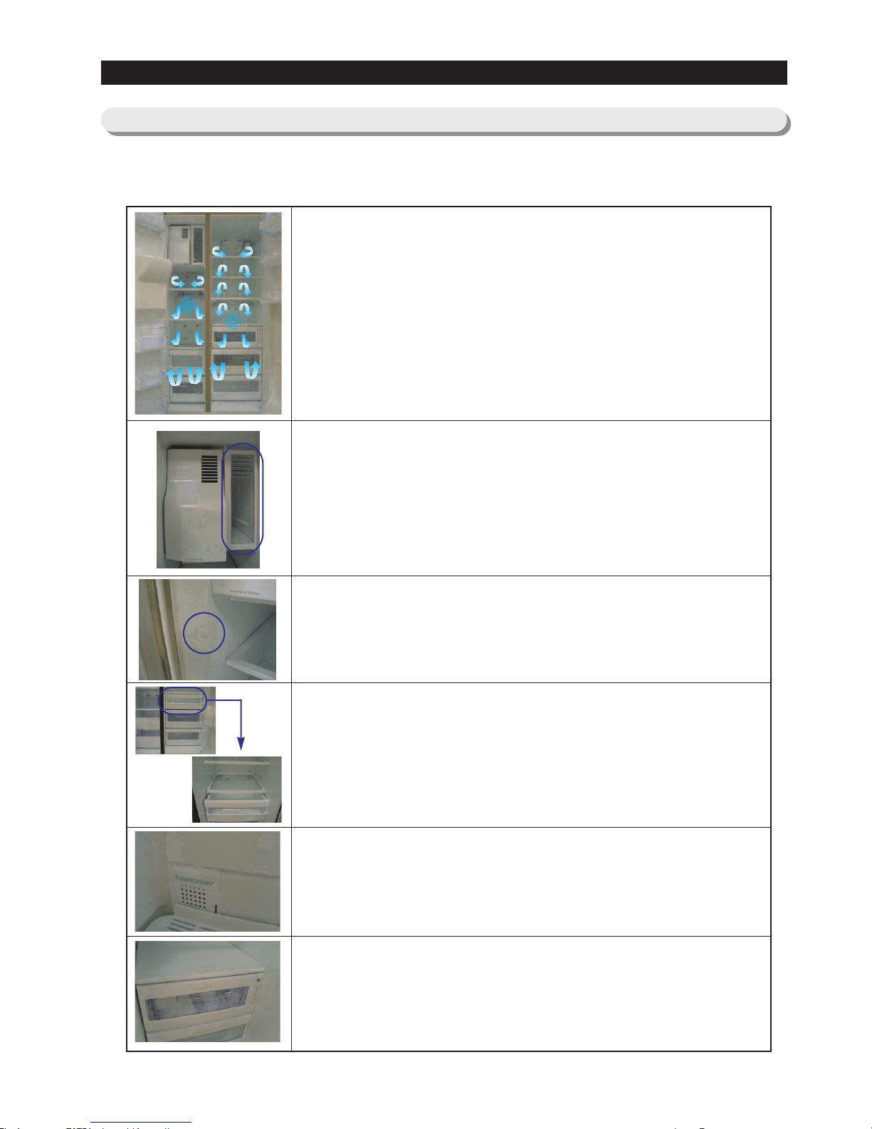
Xtra Fresh
TM
●●
Optimized humidity control keeps vegetables & fruits fresh.
(RS263B/RS265L)
Deodorizer
●●
Reusable twin deodorizers keep the refrigerator air fresh and odor
free.
CoolSelect ZoneTMDrawer
(RS265B,RS267B,RS267L,RS269L)
●●
User can select Quick Cool, Thaw, for quickly chill items, thaw
items. Select Soft freeze, Chill or Cool to control the temperature
of the drawer.
2-1) Introduction of main function
9
2-2) Specifications
2. PRODUCT SPECIFICATIONS
Defrost Control From 24 to 32 hrs
Defrost Thermistor(502AT) 50℉(off)
Electrical Rating AC115V 60Hz 11.6 Amps
Maximum Current Leakage 0.25 mA
Maximum Ground Path Resistance 0.1 Ohm
Energy Consumption KWH/mo.
Ambient Temperature 70
℉ 90℉
Refrigerator,℉ 34∼46 34∼46
Freezer,℉ -14∼8 -14∼8
Run Time,% 40 60
Refrigerant Charge (R134a) 7.76 oz
Compressor(MK183C-L2U) 532.3 Btu/hr
Compressor oil Freol α-10
Capillary tube(Dia, Length)
0.033"",130
""
Dryer
Molecular Sieve XH-9
Clearance must be provided for air circulation
AT TOP 2
""
AT SIDES 0.1
""
AT REAR 2
""
RS265(Good), RS267(Better), RS269(Best)
Main PCB ASS’Y(Dispenser with CoolSlelect Zone
TM
)
DA41-00104Z
Main PCB ASS’Y
(
(Dispenser
)
DA41-00396A
Thermistor(Freezer) DA32-10109W
Thermistor(Freezer Evaporator) DA32-00006A
Thermistor(Refrigerator) DA32-10105U
Thermistor(Refrigerator Evaporator)
DA32-00006B
Thermistor(Ambient) DA32-10109V
Thermistor(CoolSelect ZoneTM)
DA32-10109X
Thermistor(Ice-Maker)
DA32-10108B
Relay DA35-10013Q
Overload Relay DA34-10003D
Run Capacitor (12㎌) 2501-001045
Fan-Motor(FRE) DA31-00020E
Fan-Motor(REF) DA31-00002S(RS2534)
Fan-Motor(REF) DA31-00020E(RS2556/2578)
Fan-Motor(Condenser) DA31-00020H
Thermal Fuse DA47-00095C
Senser-Flow DA32-10110B
Fan
Fan
(Air inlet)
(Air inlet)
Heat exchanger
Compressor
C-FanDryer Electric box
Sub-condenser
ELECTRICAL SPECIFICATIONS Freezer Refrigerator
NO LOAD PERFORMANCE
REFRIGERATION SYSTEM
INSTALLATION
MODELS
REPLACEMENT PARTS
Fan
Fan
Fan
Heat exchanger
Heat exchangerHeat exchanger
(Air inlet)
(Air inlet)
Fan
(Air inlet)
(Air inlet)
10
2. PRODUCT SPECIFICATIONS
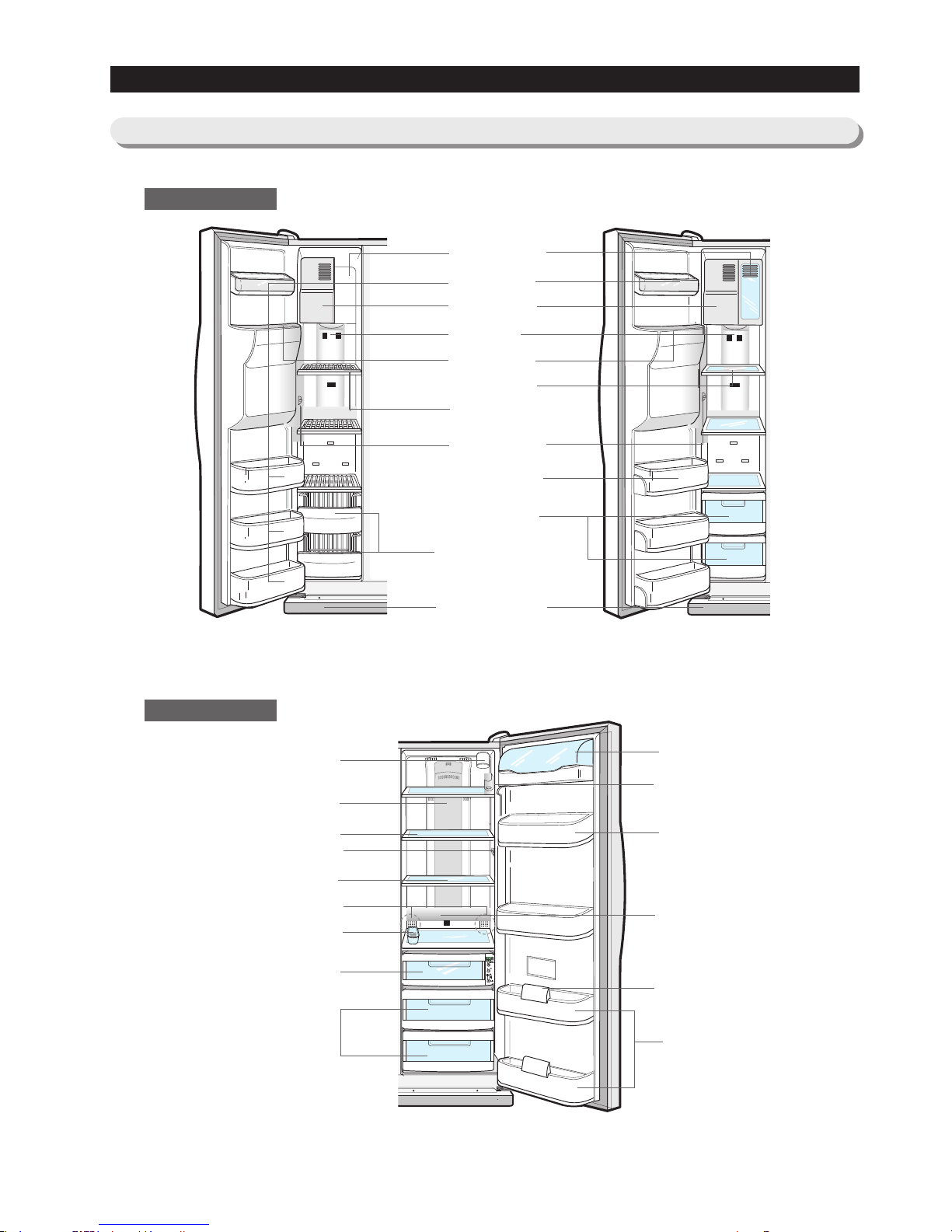
2-3)
Interior Views
Door Bin
Xtra Space
TM
Ice Maker
Light
Ice Chute
Glass Shelf
Wire Shelf
Light Switch
Light Switch
Deodorizer
Plastic Drawers
Wire Drawers
Front Leg Cover
Tilt Pockets
RS263B/RS265L Model
Egg Container
Foldable Shelf
(RS265B/RS267B/RS267L/RS269L)
Light (upper)
Water Filter
Spill-proof glass Shelf
Dairy Compartment
Wine Shelf
Gallon Door Bin
Lights (lower)
Gallon Door Bins
Door Bin Top Lips
CoolSelect Zone
TM
Drawer for
RS265B/RS267B/RS267L/RS269L
(Chilled Bin for RS263B/RS265L)
Vegetable & Fruit Drawers
RS265B/RS267B/RS267L/RS269L Model
Freezer
Refrigerator
11
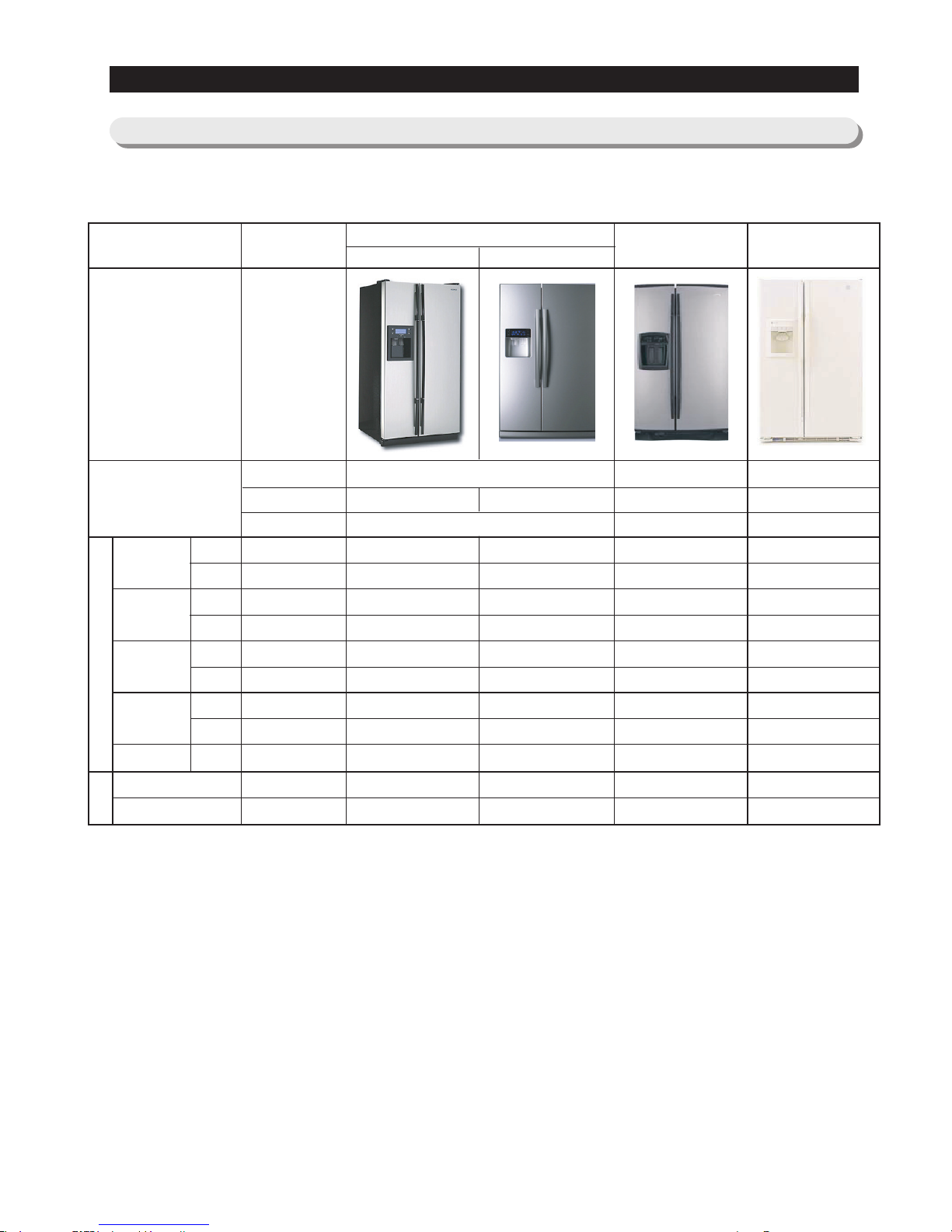
2-4) Model Specification &Comparison Chart
PRODUCT SPECIFICATIONS
Spec
WHIRLPOOL
GS6SHAXLS
GE
GSS25JFP
ITEM
Appearance
Product Zone
Performance
Noise
SAMSUNG
Twin Cooling
Flat Contour
Cool select Zone
167.2 159.3 111.6 199.0
108.5 104.2 386.4 202.0
-29.9 -30.0 -29.8 -27.2
0.1 -1.0 -4.6 -1.1
-24.0 -23.7 -24.7 -20.4
1.3 -0.3 3.4 1.1
1.3 0.9 1.7 1.0
1.5 1.2 2.1 3.3
53.2 55.5 48.8 55.3
44.4 43.3 45.0 46.7
41.3 41.1 40.0 45.0
Cooling Tech
Door Shape
Special Room
Mono Cooling Mono Cooling
Contour Contour
Convertible Bin Convertible Bin
A-TOP05 A-TOP06
200↓
150↓
-26↓
0±1.5
-18↓
5↓
2.0↓
2.0↓
65%↓
45dB↓
43dB↓
F-Room
Cooling
Speed(Min)
32℃
43℃
Temperature
Distribution
(Fridge)
Operation rate
R-Room
F-Room
R-Room
F-Room
R-Room
F-Room
R-Room
N-N
Sound power level
Sound pressure level
12
2-5) Model Specification &Specification Chart
PRODUCT SPECIFICATIONS
Indirect Cooling Method Refrigerator
R134a
7.76oz
309 Pounds
35.7inch x 36.5inch x 70inch
AC 115V/60Hz
Net Dimension(W×D×H)
Rated Frequency and Frequency
Motor Rated Consumption Power
Electric Heater Rated Consumption Power
Kind of Refrigerator
Refrigerant
Refrigerant Input Amount
Product Weight
Item
Specification
NNeett
CCaappaacciittyy
TToottaall
RReeffrriiggeerraattoorr
FFrreeeezzeerr
Models
26.1 cu.ft
10.0 cu.ft
16.1 cu.ft
414W 415W
160W
Dispenser
Dispenser with
Coolselect Zone™
RS263BB RS265LB RS265BB RS267LB RS267BB RS269LB
Items
13
PRODUCT SPECIFICATIONS
THERMISTOR
(R-SENSOR)
502AT
Models
Condenser
Dryer
Capillary tube(Dia
×
Length)
Refrigerant
FREOL α-10
SPLIT FIN TYPE
SPLIT FIN TYPE
Forced and natural convection type
Molecular sieve XH-9
0.033 ”×130 ”
R134a
ON(℉) OFF(℉)
-11℉ -17℉
-1℉ -7℉
11℉ 5℉
ON(℉) OFF(℉)
36℉ 32℉
40℉ 36℉
46℉ 42℉
4 hr ± 10 min
12~24hr(vary according to the conditions used)
6~12hr(vary according to the conditions used)
10 ± 2 min
THERMISTOR (502AT)
5.0㏀ at 50℉
THERMISTOR (502AT)
5.0㏀ at 50℉
AC 125V 10A
Off:140 ℉/On:104℉
AC 250V 10A
170.6 ℉(+0 ℉/-10 ℉)
Components for Freezer
Room Temperature Sensor Components
Freezer
Model
Temperature Selection
-14℉
-4℉
8℉
THERMISTOR
(F-SENSOR)
502AT
Model
Temperature Selection
34℉
38℉
44℉
Refrigerator
Defrost Cycle
Defrost SensorThermal-Fuse
F Defrost-
Sensor
F Bimetal-
thermo
R Thermal
Fuse
R Defrost-
Sensor
First Defrost Cycle (Concurrent defrost of F and R)
Defrost Cycle(FRE)
Defrost Cycle(REF)
Pause time
Model
SPEC
Model
SPEC
Rated
Operating temperature
Rated
Operating temperature
Defrost Related Components
Compressor
Model
Starting type
Oil Charge
Evaporator
Freezer
Refrigerator
MK183C-L2U
R.S.C.R
RS263 RS265 RS267 RS269
Specification
14
PRODUCT SPECIFICATIONS
Electric Components
AC 115V,215W
AC 115V,140W
AC 115V,45W
Single Body with Defrost Heater(REF)
AC 125V 10A Off:-76 ℉/On:104 ℉
AC 250V 10A 170.6 ℉(+0 ℉/-10 ℉)
Specification
Items
Model
Conducting at F Defrosting
Conducting at R Defrosting
Conducting at F Defrosting
Conducting at R Defrosting
Interlock with F-FAN
-
-
Defrost Heater(FRE)
Defrost Heater(REF)
Drain Heater(FRE)
Drain Heater(REF)
DISPENSER Heater
WATER PIPE Heater
WATER TANK- Heater
Condenser for
COMP
(Package type)
Running
Starting
Model
Operation
Model
Temp. ON
Temp. OFF
Starting-Relay
Over load Relay
MOTOR-BLDC(FRE)
MOTOR-BLDC(REF)
MOTOR-BLDC (Circuit)
Lamp(FRE)
Door Switch
Power cord
Earth Screw
Bimetal-thermo for preventing
Overheating of Freezer Defrost-Heater
12μF,250
V
-
J531Q32E4R7M180-2
4.7Ω±20%
4TM265RFBZZ53
257 ℉±10
℉
156.2℉±18
℉
AC 115V/60Hz
DC12V/DREP3030 LA
DC12V/DREP3020 LA
DC12V/DRCP3030 LA
AC115V/40W(1EA)
AC120V/40W(3EA)
AC 250V 0.5A×2
AC125V 15A
BSBN (BRASS SCREW)
Thermal Fuse for preventing
Overheating of Refrigerator Defrost-Heater
Rated Voltage
AC 115V,5W
AC 115V,5W
AC 115V,4W
RS263BB
RS265LB
RS265BB
RS267LB
RS267BB
RS269LB
Lamp(REF)
UPPER
LOWER
AC130V/30W(1EA)-
15
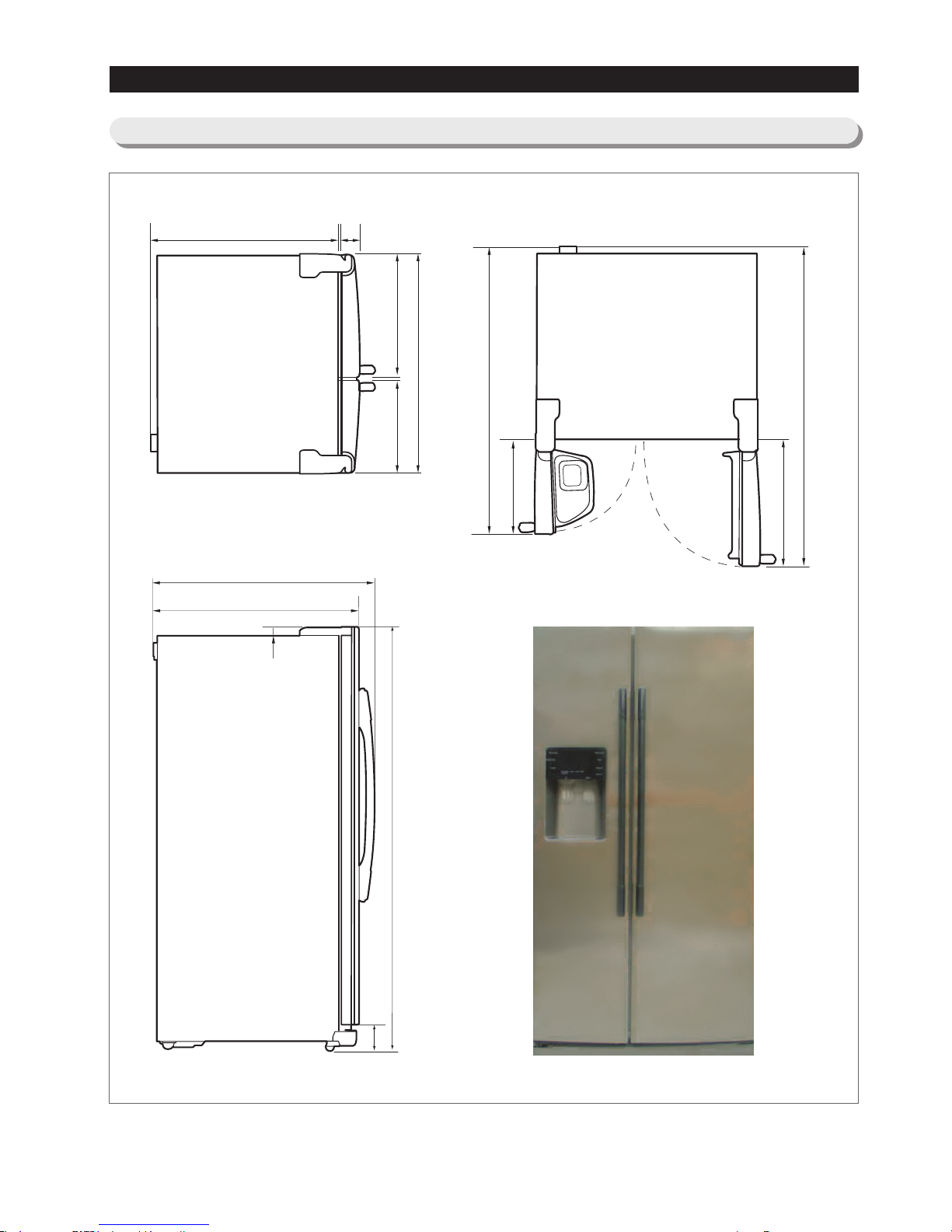
2. PRODUCT SPECIFICATIONS
35.9
46.8
16.3
21.2
51.7
20.3
30.5
36.5
34
3
15.3
1.2
4.3
70
2-6)Dimensions of Refrigerator (Inches)
16
2. PRODUCT SPECIFICATIONS
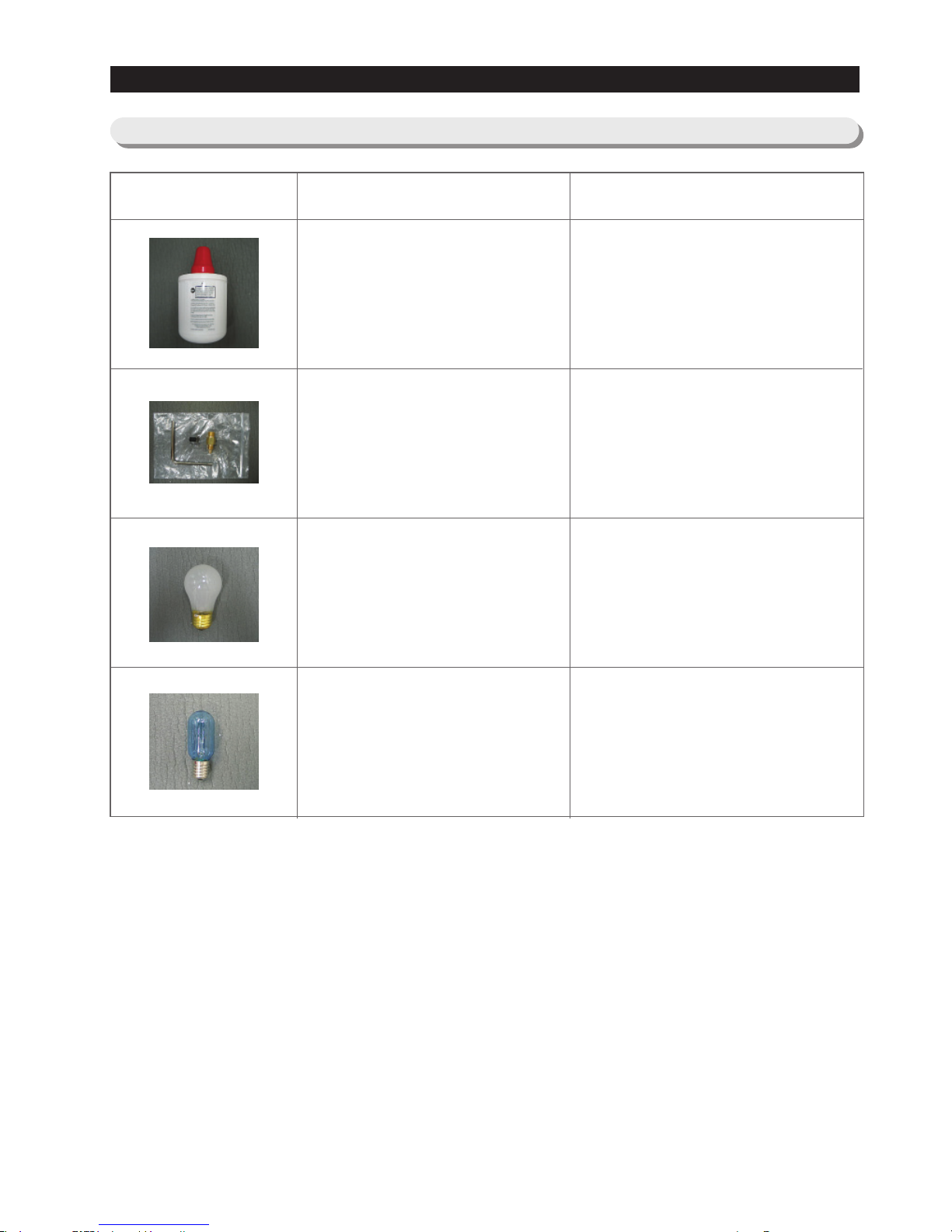
2-7) Optional Material Specification
Photographe Part Name
FILTER
WATER-ASSY
DA29-00003B
ASSY-PACKING
SUB
DA99-00240A
LAMP INCANDENT
4713-001206
LAMP INCANDENT
4713-001197
Part Code

17
Compressor → Sub-condenser → Side Cluster Pipe(FRE) → Side Cluster Pipe(REF) → Hot Pipe
→ Dryer → Capillary Tube → Refrigerator Evaporator → Freezer Evaporator→ Suction Pipe → Compressor
Refrigerator Evaporator
Capillary Tube
ACCUMULATOR
Freezer Evaporator
SUCTION PIPE
Dryer
Muffler
SUB-CONDENSER
Hot Pipe
Hot Pipe
Compressor
SIDE CLUSTER PIPE
2. PRODUCT SPECIFICATIONS
2-8) Refrigerant Route in Refrigeration cycle
18
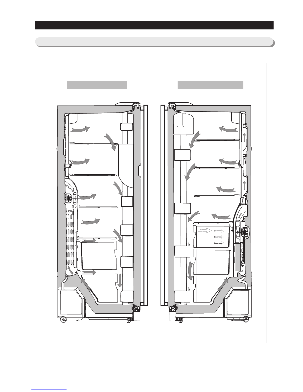
Refrigerator
2. PRODUCT SPECIFICATIONS
2-9) Cooling Air Circulation
Freezer

19
3. OPERATING INSTRUCTIONS & INSTALLATION
3-1) Digital Panel ······································20
3-2) Temperature Control Function
····························20
3-3) Power Freeze and Power Cool Functions
······················21
3-4) Child Lock Function
··································21
3-5) Ice & Water Dispenser Function
···························22
3-6) C-Fan Motor Delay Function of the Machine Compartment
···········22
3-7) CoolSelect ZoneTM Function (RS267LA,RS269LA)
···············22
3-8) Water Filter Indicator Function
····························23
3-9) Ice-Maker Function
··································23
3-10) Defrost Function
···································25
3-11) Installation
·······································26
20
3. OPERATING INSTRUCTIONS & INSTALLATION
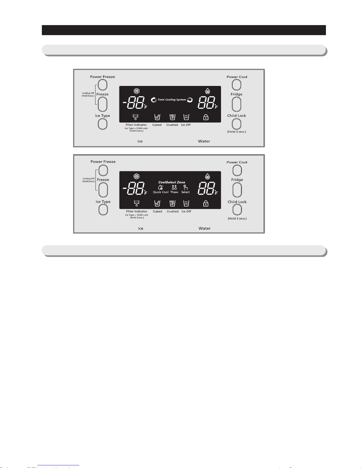
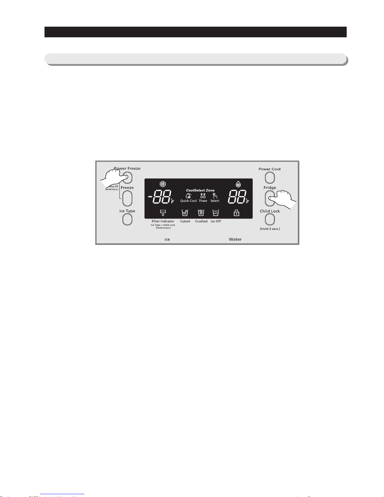
3-1) Digital Panel
When the system power is initally engaged, the default set temperature are -4℉ for the freezer and 38℉ for the set
refrigerator, respectively. The numbers shown on the digital display panel stand for the actual compartments
temperatures. When the compartment temperatures go down, so do the numbers on the display panel, and finally they
reach the set temperatures. Once the system is stabilized, the display temperatures are the set temperature.
1) Freezer Temperature Control.
To select a set temperature, press the Freezer Temp. button. The display shows the set temperature from -14℉ to
8 ℉ in sequence.
2) Quick Ice Freezer Temperature Control
Interior Temperature of the freezer will be controlled with -14 degrees Fahrenheit until the ice bucket is filled up with
ice cubes. When the ice bucket is filled up with ice cubes, the freezer will run with original set temperature. Also,
whenever the ice bucket is released from being filled with ice cube, the freezer will repeat
to be controlled with -14 degrees Fahrenheit. But if you select "Ice Off, the freezer always will be controlled with
original set temperature.
3) Refrigerator Temperature Control.
To select a set temperature, press the Fridge Temp. button. The display shown the set temperature from 34℉ to
46℉ in sequence.
note) Because of the temperature sensor sensivity, the refrigerator can be under and/or over cooled when
the air flow is blocked by stored foods. (Temperature range of the sensor : 15℉∼80℉)
In the event of a power failure, if the freezer temperature is maintained lower than 41℉, the last
selected set temperature and functions memorized in EEPROM will be restored when the power is on.
for RS263BB
RS265LB
for RS265BB
RS267BB
RS267LB
RS269LB
3-2) Temperature Control Function

21
3. OPERATING INSTRUCTIONS & INSTALLATION
3-3) Power Freeze and Power Cool Functions
3-4) Child Lock Function
● Select the Power Freeze or Power Cool buttons separately.
● These buttons are toggled ON and OFF and the indicators as well.
● Although you select Power Freeze or Power Cool, the set temperatures in the freezer and refrigerator are not
changed.
● The set temperatures for the compartments can be changed while these functions are in use.
1) Power Freeze function
1-1) When you press the Power Freeze button, the LED indicator lights right away, but there is 10 seconds lag time to
an actual
operation. When this button is pressed again, the Power Freeze function stops and the indicator is off
immediately .
1-2) If you select Power Freeze, both the compressor and the freezer fan run for 2.5 hours continuously.
1-3) During Power Freeze, the freezer retains the current settings.
1-4) When Power Freeze expires, the indicator goes off and the freezer set temperature will be restored.
2) Power Cool function
2-1) Power Cool operation and the indicator work exactly same as the Power Freeze function.
2-2)When Power Cool is selected, COMP and Refrigerator Fan operate continuously until the refrigerator reaches
25℉. This function will be terminated after 2
½ hr running.
3) When you select Power Freeze and Power Cool together
Each function works at the same time. The COMP and Freezer Fan run continuously and the Refrigerator Fan runs
until 25℉in the refrigerator.
4) Initial Power-On
4-1
) When the freezer and the refrigerator temperatures are higher than 14℉ and 50℉, respectively, if Power
Freeze is selected, then the Refrigerator
Fan
will be off. If Power Cool is selected, then the Freezer
Fan
will be off.
4-2) When both functions are selected, there is no benefit of fast cooling for each compartment.
● When the child lock button is pressed for 3 seconds, the child lock indicator is on with an audible tone.
-When it is locked, no function commands except the Ice type button.
-This function will prevent accidental setting that may be caused by children or pets.
-To unlock the setting functions, press this button for 3 seconds again.
22
3. OPERATING INSTRUCTIONS & INSTALLATION
3-5) Ice & Water Dispenser Function
3-6) C-Fan Motor Delay Function of the Machine Compartment
3-7) CoolSelect ZoneTMFunction
(RS267LA,RS269LA)
● Among several ice-maker functions, the ice extraction function is performed by mechanical system. Only the relay
control for a cubed-ice dispensing and the SSR control for the ice chute door are performed electronically.
1) Select Cubed/Crushed/Ice-off function
1-1) The Ice Type button selects Cubed/Crushed/Ice-off options in sequence.
1-2) A default setting is Cubed option.
1-3) If Cubed ice is selected, the Crushed ice bypass solenoid and the geared motor will allow Cubed ice to by pass
the ice Crusher.
1-4) If Ice-off is selected, the ice maker will stop working. This option will be terminated when Cubed and Crushed
options are selected.
1-5) The ice chute door must remain open for 5 seconds after dispensing ceases. After this 5 seconds delay, SSR will
be controlled to shut the ice chute door.
2) Water Dispenser function
2-1) To dispense water, depress the water dispenser lever located in the dispenser recess.
2-2) When the lever is depressed, the water solenoid valve located in the machine compartment is open to flow water.
2-3) There is no electronic control function for this option.
● According to the ambient temperature, the condenser fan located in the machine compartment is operated with
different modes.
● To select this function, open the refrigerator door and press the button on the control panel of CoolSelect Zone
TM
drawer.
● When the CoolSelect Zone
TM
function is selected, the damper inside fan ductwork is open. So the refrigerator cooling
is performed first, then the damper is closed to control the CoolSelect Zone
TM
temperature.
Note) When the Ice-off indicator is on, only Cubed ice will be dispensed from the ice bucket.
Caution) Do not force to close the ice chute door. Try to dispense some more ice again to work it automatically.
Ranges of ambient temp.
Above 66℉
61℉ ~ 65℉
Below 60℉
Condenser-Fan is ON as soon as the compressor is on.
Condenser-Fan is ON with 5 minutes delay from the compressor on.
Condenser-Fan is OFF regardless of the compressor operation.
Condenser Fan
Delay function
Operation
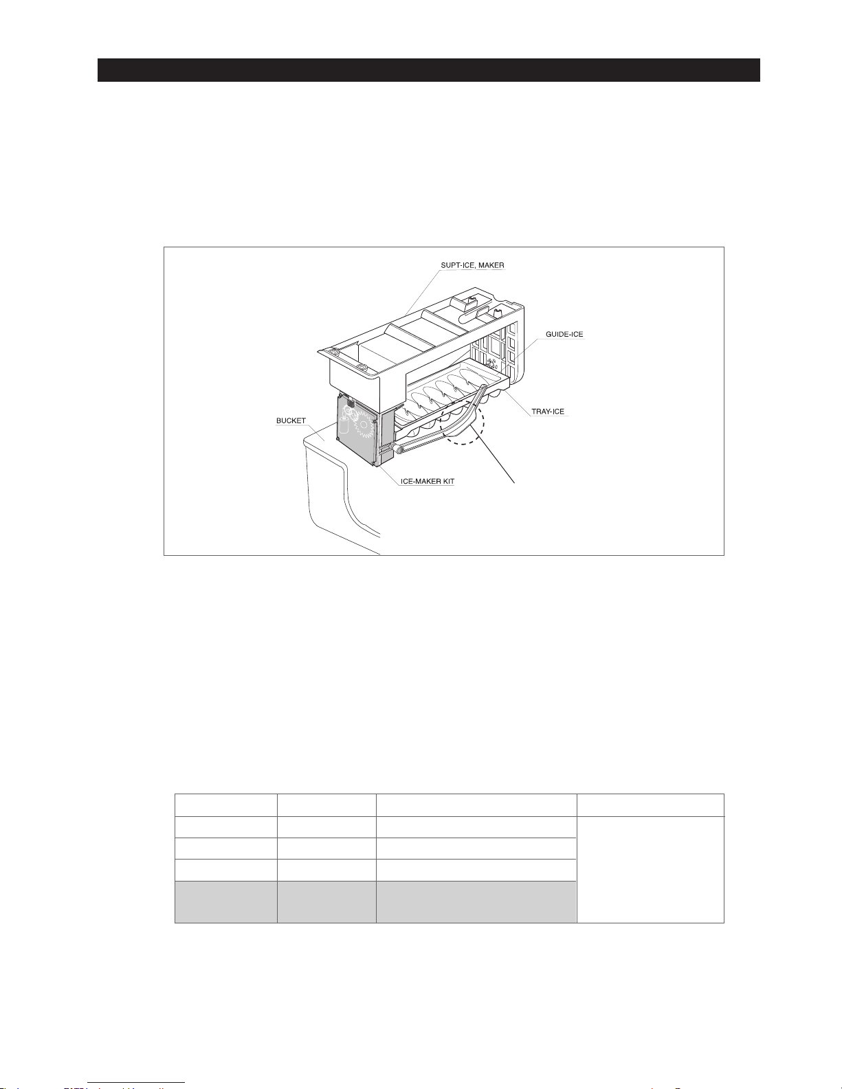
23
GUIDE-ICE(Lever to check ice full)
KNOB-TOUCH
1) Select function
1-1) Using Select button, Cool, Chill(30℉), and Soft Freeze(23℉) options can be selected in sequence. Cool option
maintains a set temperature of the refrigerator.
2) Quick Cool function
2-1) If the Quick Cool is selected, LEDs will flash 60 and Min. The count will be decreased in every minute.
2-2) To cancel this function, press Quick Cool button again or Thaw button or Select button. Otherwise, it will be
terminated 60 minutes later automatically.
2-3) After this function ends, this drawer will come back to Cool option.
2-4) A defrost cycle will be postponed until Quick Cool option is finished.
3) Thaw function
3-1)When the thaw button is pressed, LEDs will flash 4, 6, 10, and 12 in sequence and Hr.
3-2) The count will be decreased in every hour.
3-3) A cancellation of this function is the same as Quick Cool function.
3-4) After this function ends, this drawer will be maintained with 30℉.
3-5) While the compressor is on, this drawer retains a certain temperature and while the compressor is off, the defrost
heater is activated and Refrigerator Fan is on with a closed position of the damper.
1) Filter Indicator
1-1)This indicator initially lights in green. The light color will be changed to orange after 5 month operation then to red
at the 6th month. The EEPROM in the control board counts a period of time regardless of a power failure.
1-2)To reset the counter and the light color, press Ice Type button and Child lock button for 3 seconds simultaneously.
1-3)If these two buttons are pressed simultaneously for 5 seconds, this function will cease.
1-4)To restore this function, press these buttons again for 3 seconds.
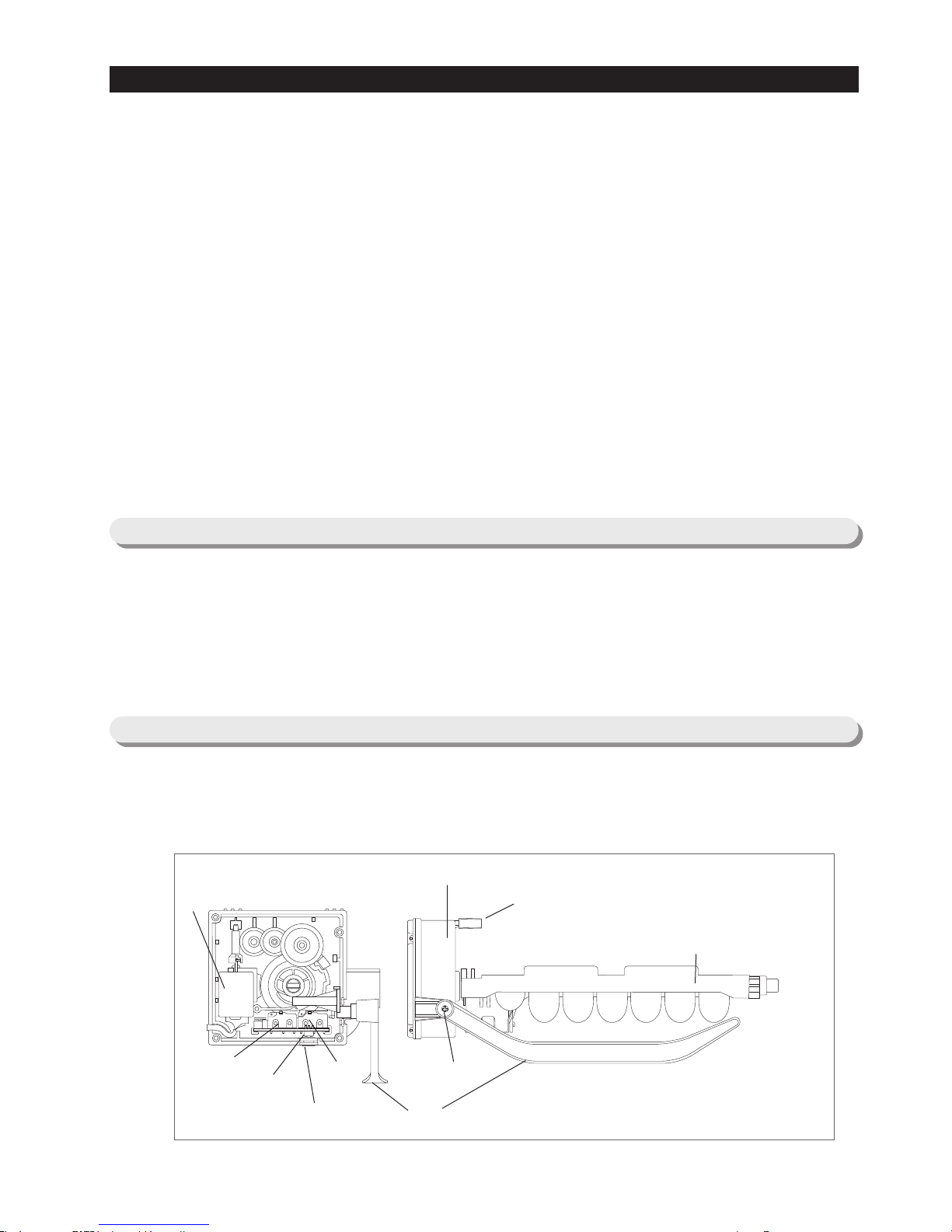
● The Ice-maker is referred to the device with an automatic ice production, storage in the ice bucket and dispensing
through the ice chute.
1) Ice-maker parts
TRAY-ICE
SCREW
SUPT-RUBBER
ICE-WAKER, KIT
EJECT-MOTOR
TEST-SWITCH
LEVELING-SWITCH
ICE Full-
SWITCH
3. OPERATING INSTRUCTIONS & INSTALLATION
3-8) Water Filter Indicator Function
3-9) Ice-Maker Function
24
3. OPERATING INSTRUCTIONS & INSTALLATION
<Reference table>
Leveling S/W
ON(“LOW”)
ON(“LOW”)
OFF(“HIGH”)
OFF(“HIGH”)
Ice full S/W
ON(“LOW”)
OFF(“HIGH”)
ON(“LOW”)
OFF(“HIGH”)
Remark
·MICOM Port
PIN #51: Leveling
PIN #51: Ice full
·Port level
OFF : 4.5V ↑
ON : 0.5V ↓
Judgement
Not ready
Not ready
Not ready(Ice bucket with full of ice )
Ready
2) Preparation of Ice-maker
2-1) Connect the water line to the water supply valve of refrigerator to supply water. (See how to connect a water
supply line in the owner’s manual.)
2-2) Push the bucket back fully so that the guide-ice of ice maker should not touch the back of bucket. (If the back of
bucket is touched the guide-ice of ice maker, the ice maker will not make ice any more because of a ice full signal.)
2-3) It takes 6 hours to harvest a first ice, and throw away 2-3 times of these ice to make sure the supplied water clean.
1) Initial Operation function
1-1) Whenever the power is on, the control board checks the ice tray leveling with the leveling switch within 2 seconds.
1-2) If the leveling switch is not off position, the geared motor will turn to the initial position to make the ice tray leveled.
1-3) When the ice tray is leveled, it will remain this position for 2 hours (1 cycle time for ice production).
1-4) After 2 hours, the sensor located under the ice tray will measure the tray temperature. If the temperature is
maintained lower than 1℉ for 5 minutes, and the ice full switch is off position, the ice tray twisting process will
begin.
Push the bucket back fully so that the
lever should not be pushed up.

25
3. OPERATING INSTRUCTIONS & INSTALLATION
2) Water Supply function
2-1) When the ice tray is levelled again after ejecting ice, the water solenoid value will be controlled to supply water by
time check basis. (See the “Time to supply water” Table)
3) Ice production
3-1) After 60 minutes pass from the water supply, the control board will check the temperature.
3-2) If the sensor reads the temperature lower than 1℉ for more than 5 minutes, than the ice production process is
completed.
4) Test function
● In order to operate a test function, press the knob (Test Switch) for 1.5 second.
● This function can be used to check a proper working, to clean the ice tray, and to adjust the water level in the ice tray.
4-1) This function only works when the ice tray is leveled and the ice full signal is cleared.
4-2) When the water line is connected, each process such as a water supply, ejection, and leveling, can be investigated
by this button.
5) Ice off function
5-1) When the Ice off option is selected by Ice Type button, the ice making process will cease.
5-2) When the ice making process ceases, the final state will be the ice tray with supplied water.
5-3) When Cubed or Crushed option is selected again, the control board will check an accumulated time period. After
making it 60 minutes and when the ice tray temperature is acceptable, ice ejection process will begin.
6) Functions when the freezer door is open
● When the freeze door is open, all ice maker related processes will cease in order to minimize noise and to prevent ice
from dispensing.
6-1) The ice tray stops moving regardless of the position.
6-2) The water supply process remains working as usual.
6-3) If the ice tray is in the middle of ice ejecting process, close the freezer for 30 seconds and check if the tray is
leveled. If it is not leveled, it must be out of order.
1) A defrost is determined based on the accumulated compressor on-time.
2) When the power is engaged for the first time, the defrost cycle for the freezer and the refrigerator will begin after 4
hours of the accumulated compressor on-time.
3) A defrost interval depends on the ambient temperature, the number of door openings, and the door open time.
4) A minimum interval is 6 hours and a maximum is 8 hours for the refrigerator, and 12 hours and 16 hours for the
freezer, respectively.
5) The defrost heater on-time is determined by the defrost sensors as follow :
3-10) Defrost Function
Freezer
Below 50
℉
Refrigerator
63
℉
Heater ON
Heater OFF
-
50
℉
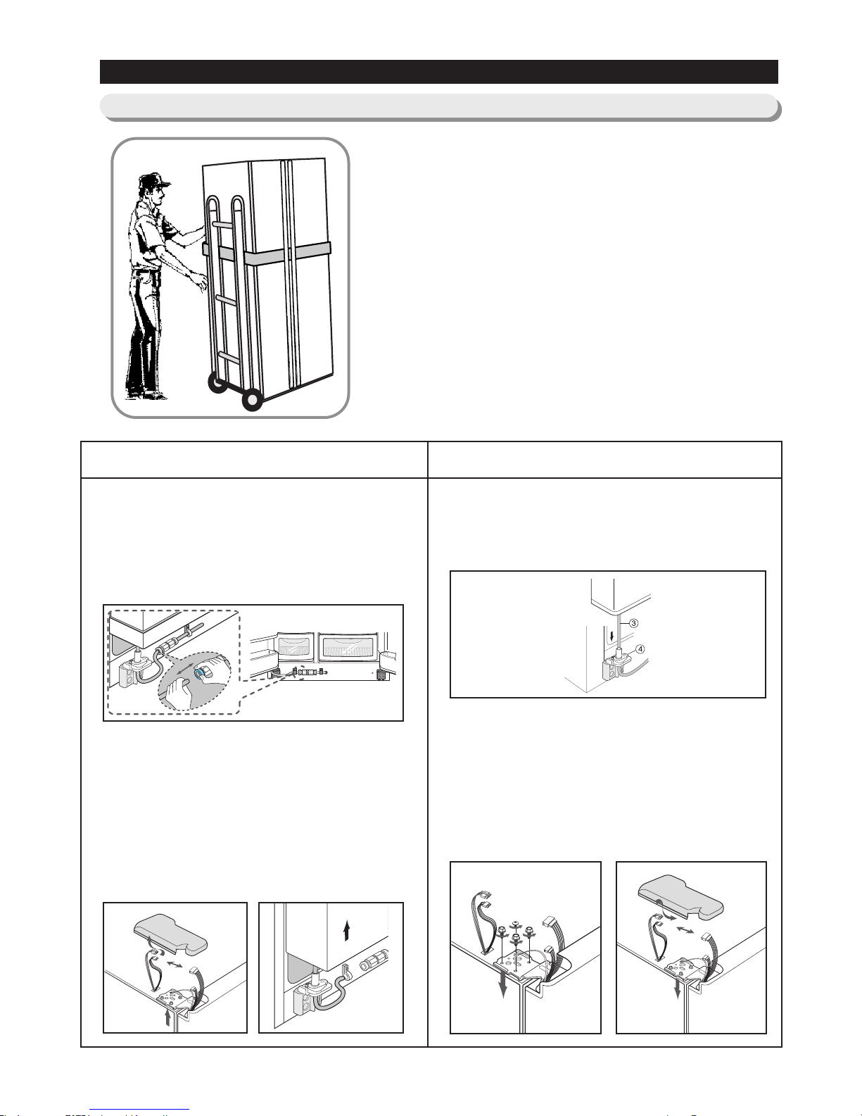
●●
Removing Doors
Open the freezer and refrigerator doors, and
then take off the front leg cover assembly by
turning the three screws counter-clockwise.
Remove the screw from clamp, disconnect the
water tube by pressing the coupler, and pulling
the water tube away.
With the door closed, remove the upper hinge cover
using a screwdriver, and then disconnect the wires.
Remove hinge screws and ground screw counterclockwise, and take off the upper hinge. Take care
removing the door to ensure that it does not fall on you.
Remove the door from the lower hinge by carefully lifting
the door so as not to damage the water tube. Remove
the lower hinge from the lower hinge bracket by lifting
the lower hinge.
●●
Attaching Doors
Insert the lower hinge in the bracket lower
hinge. Attach the freezer door by inserting the
hose in the lower side of the door into the hole
in the lower hinge and pulling the hose down.
Insert the upper hinge shaft into the hole. After
leveling between the upper hinge hole and the
hole of the cabinet. Reattach hinge screws and
ground screw in the clockwise direction.
Connect the wires. (Put the front part of the
upper hinge cover on the front part of the
upper hinge and reattach from the front part
of the upper hinge cover first. )
26
3. OPERATING INSTRUCTIONS & INSTALLATION
3-11) Installation
1) To protect refrigerator in movement
Use padded hand truck as shown. If entrance width is
less than 39〃, remove doors prior to installation and
reattach doors according to procedure below.
2) Remove all protective tape and pad in refrigerators.
Connect water lines and power cord. Adjust the
clearance between the doors.
3) Set the temperature control to the temperature and
wait for an hour.
The refrigerator should get slightly chilled and the motor
runs smoothly.
4) Once the refrigerator temperature is sufficiently low
You can store food in the refrigerator. After starting the
refrigerator, it takes a few hours to reach the appropriate
temperature.

27
4. ALIGNMENT AND ADJUSTMENTS
4-1)
Forced Operation Function (Pull-down / Refrigerator Defrost / Refrigerator . Freezer-Defrost / Cancellation)
·28
4-2) Sound function
·····································29
4-3) Cooling Off Function
·································29
4-4) Self-Diagnostics Function
·······························29
4-5) Load Operation Check Function
···························31
4-6) Restoration Function for Power Outage
·······················31
4-7) Set Point Shift Function
································31
4-8) Table of Set Point Shift Function
··························32
28
4. ALIGNMENT AND ADJUSTMENTS
4-1)
Forced Operation Function (Pull-down / Refrigerator Defrost / Refrigerator . Freezer-Defrost / Cancellation)
● This function enables a pull-down mode, a defrost mode for the refrigerator only, a defrost mode for the freezer and the
refrigerator at the same time, and a cancellation of this function.
● Press Power Freeze and Fridge Temp. buttons for 8 seconds simultaneously to get in the ready mode for a forced
operation.
● The display panel will return to normal after 20 seconds in the ready mode.
● At the ready mode, press any button(except Ice Type and Child Lock) once to start a pull-down operation, twice for a
defrost cycle for the refrigerator, three times for a defrost cycle for the freezer and the refrigerator, and finally four times
for cancellation of this function.
● Another way to cancel this function is to simply plug out and in the power cord.
1) Pull-down
1-1) At the ready mode, press any button once then the buzzer will beep (ON for 1/2 second and OFF for 1/2 second)
until this mode is cancelled.
1-2) At this pull-down mode, the compressor will start immediately (No 5 minute delay) and if the system is in the
defrost cycle, it will be cancelled right away.
note) If this pull-down mode begins right after the compressor was off, the compressor may not start to run due to an
overload condition.
1-3) At this mode, the compressor and freezer fan will operate continuously for 24 hours and the refrigerator fan will be
on and off according to the set temperature(34℉)
1-4) After 24 hour operation, the system will be cycled at -14℉ for the freezer and 34℉ for the refrigerator.
1-5) In order to cancel this mode at any time, select the next mode on the ready mode or power off the system.
2) Refrigerator Defrost / Refrigerator . Freezer-Defrost operation
2-1) At the pull-down mode, press any button again on the ready mode to begin the defrost cycle for the refrigerator.
2-2) The beep sound continues for 3 second at the beginning, then ON for 3/4 seconds and OFF for 1/4 second until
this mode cease.
2-3) After this operation, the system will come back to normal operation.
2-4) At this mode, press any button again on the ready mode to operate the defrost cycles for both compartments.
2-5) The beep sound continues for 3 seconds at that time, then ON for 1/4 second and OFF for 3/4 seconds until the
defrost operation cease.
3) Cancellation
3-1) At the R,F-Defrost mode, press ant button again on the ready mode to return to a normal operation.
3-2) Simply unplug the power cord, then plug it again to return to a normal operation.
Press both button for 8seconds at the same time

29
4. ALIGNMENT AND ADJUSTMENTS
4-2) Sound function
1) Sound function
1-1) To make sure a command input, whenever a button is pressed, a “ding-dong” sounds.
1-2) When two or more buttons are pressed simultaneously or if a wrong button is pressed, there is no sound.
2) Door Open Alarm
2-1) When the doors remain open for 2 minutes, there are 10 times beeps.
2-2) If the doors continue to remain open more than 2 minutes, the additional 10 beeps interval will change to 1 minute.
2-3) The beeps will cease immediately when the doors are closed.
● This function is for a display purpose on the floor of show room or store.
1) Mode ON/OFF
1-1) For the Cooling Off mode, press Power Freeze and Freezer Temp, buttons simultaneously for 3 seconds until a
“ding-dong” sounds.
1-2) Press the same time buttons again for 3 seconds to cancel this mode put with a “ding-dong” sound.
2) Operation
2-1) Most of the system function except the compressor operation are working properly.
2-2) There is no defrost cycle in this mode.
2-3) “OF” is displayed on F, R Display.
2-4) Cooling Off mode is not cleared even if power is reset.
1) Self-Diagnostics in the initial Power ON
1-1)The control board performs a self diagnostics test within 1 second and check out the temperature sensors abilities.
1-2) If a sensor failure occurs, a corresponding LED segment will blink with a beep.
1-3) When a LED segment blinks, only the cancellation function (Press Power Freeze and Power Cool buttons
simultaneously for 8 seconds) is acceptable.
1-4) After a replacement of bad sensor or a cancellation of this function, this self diagnostics will end.
2) Self-Diagnostics in the normal operation
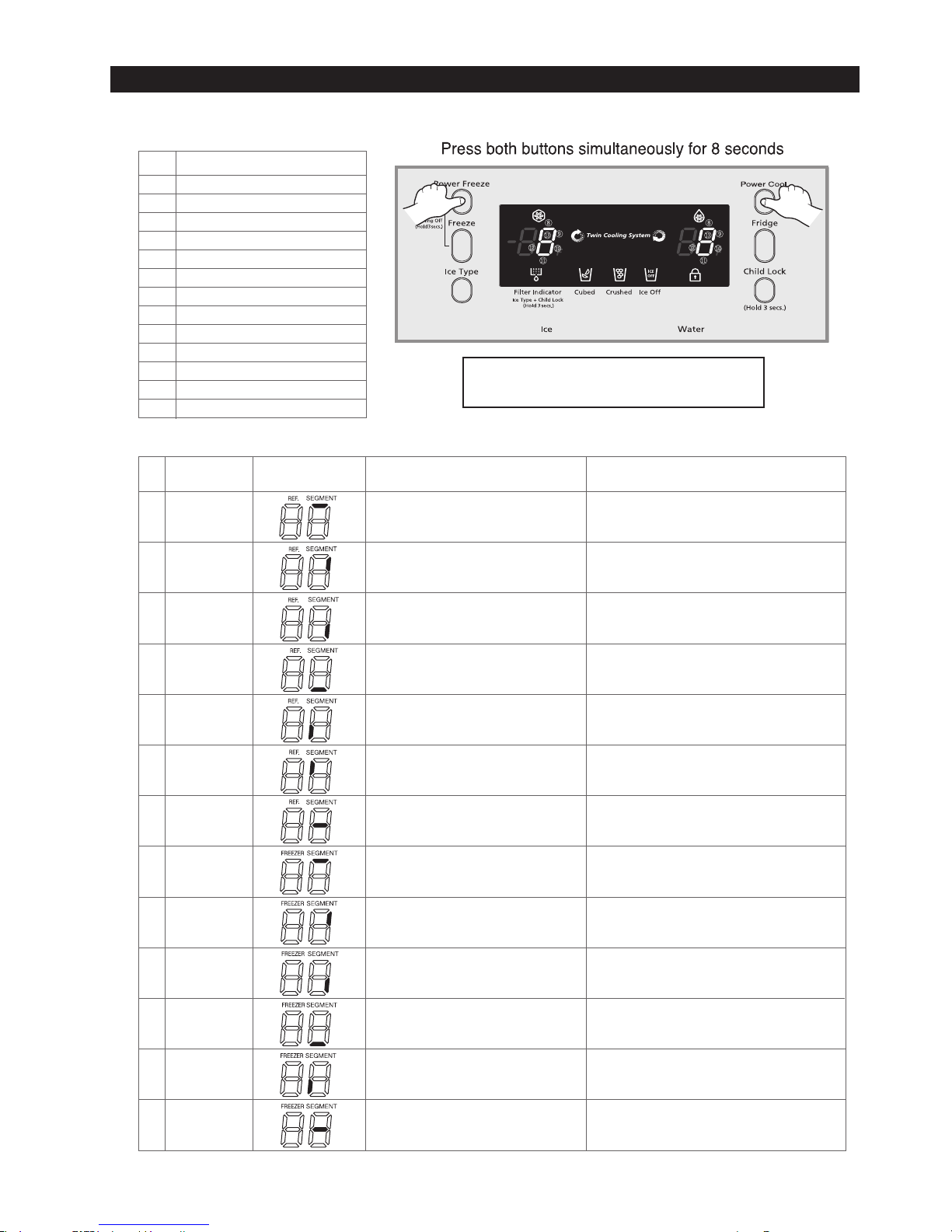
2-1) To select this function, press Power Freeze and Power Cool buttons simultaneously for 8 seconds with an audible
tone.
2-2) In the self diagnostic mode, only corresponding LED segments will be illuminated (see the check list on the next
page)
2-3) After a 30 second illumination of error signal, the system will return to the normal operation.
4-3) Cooling Off Function
4-4) Self-Diagnostics Function
30
4. ALIGNMENT AND ADJUSTMENTS
Self-diagnostics check list
If any LEDs blink, the corresponding sensors and
components must be checked for an error.
NO Error
ICE MAKER SENSOR
REFRIGERATOR SENSOR
REFRIGERATOR DEFROST SENSOR
REFRIGERATOR FAN ERROR
ICE MAKER function error
CoolSelect Zone
TM
SENSOR
REFRIGERATOR DEFROST ERROR
EXIT-SENSOR
FREEZER SENSOR
FREEZER DEFROST ERROR
FREEZER FAN ERROR
CONDENSER FAN ERROR
FREEZER DEFROST ERROR
①
②
③
④
⑤
⑥
⑦
⑧
⑨
⑩
⑪
⑫
⑬
Air sensor connector missing; contact failure,
electric wire cut, short-circuit; open air sensor
itself failure; and so on
CoolSelect
ZoneTMsensor
REFRIGERATOR
DEFROST ERROR
Ambient Air
SENSOR
The voltage should be within the range of 4.5V~1.0V
between MAIN PCB CN51 # 13 and # 14.
Read the resistance between the brown and the orange wire
terminals(the reading varies according to the basic Power Consumption.
0 Ohm→Heater Short,∞Ohm→Wire Cut or Blown Bimetal Thermo
The voltage should be within the range of 4.5V~1.0V
between MAIN PCB CN31 # 1 and # 4.
Freezer sensor connector missing; contact
failed, electric wire cut, short-circuit;Freezer
Room sensor itself failure.
FREEZER
SENSOR
The voltage should be within the range of 4.5V~1.0V
between MAIN PCB CN30 # 2 and # 3.
Freezer evaporator defrosting sensor connector
missing; contact failed, electric wire cut, shortcircuit; sensor itself failure; and so on
FREEZER
DEFROST SENSOR
The voltage should be within the range of 4.5V~1.0V
between MAIN PCB CN30 # 2 and # 4.
Freezer
Fan motor operation failure; feedback
signal line contact failure, motor’s electric wire
missing; and so on.
FREEZER FAN
ERROR
The voltage should be 7V~12V between MAIN PCB CN72 #
6(YELLOW) and # 7(GRAY).
Condenser Fan motor operation failure; feedback
signal line contact failure, motor’s electric wire
missing; and so on.
In the freezer room, if frost removal mode is
finished due to limited time of 70 minutes. Error is
displayed
CONDENSER FAN
ERROR
(COMP-FAN)
The voltage should be 7V~12V between MAIN PCB CN72 #
4(S/BLUE) and # 7(GRAY).
Read the resistance between the white and the orange wire
terminals(the reading varies according to the basic Power Consumption.
0 Ohm
→
Heater Short,∞Ohm→Wire Cut or Blown Thermo Fuse
FREEZER
DEFROST ERROR
NO Error items LED
Display
Details
How to Self-Diagnose
01
02
03
04
05
06
07
08
09
10
11
12
13
ICE MAKER
SENSOR
Ice Maker sensor connector missing; contact
failure, electric wire cut, short-circuit; Ice Maker
sensor failure; and so on
The voltage should be within the range of 4. 5V~1.0V
between MAIN PCB CN90 # 3 and # 4.
REFRIGERATOR
SENSOR
Refrigerator sensor connector missing; contact
failure, electric wire cut, short- circuit; Refrigerator
sensor itself failure; and so on
Refrigerator
Fan motor operation failure;
feedback signal line contact failed, electric wire
cut, short- circuit; and so on
The voltage should be within the range of 4.5V~1.0V
between MAIN PCB CN30 # 6 and # 7.
The voltage should be within the range of 4.5V~1.0V between MAIN PCB
CN30 # 6 and # 8.Indicate Error when the temperature sensed by
Refrigerator defrosting sensor is higher than
150℉or lower than –58℉
.
REFRIGERATOR
DEFROST SENSOR
Refrigerator evaporator internal defrosting sensor
connector missing; contact failure, electric wire cut,
short-circuit; sensor itself failure; and so on
The voltage should be 7V~12V between MAIN PCB CN72 #
5(ORANGE) and #7(GRAY).
Pusht het est b ut t ononanI / MAss' yandI tshoul d work.
REFRIGERATOR
FAN ERROR
ICE MAKER function
ERROR
Ice-ejector and level failed three times or more
Error items of self-diagnostics
CoolSelect ZoneTMsensor connector missing; contact
failed, electric wire cut, short-circuit; CoolSelect Zone
TM
sensor itself failed; and so on.
In the refrigerator room, if frost removal mode is
finished due to limited time of 80 minutes. Error
is displayed.
 Loading...