

Samsung RS2666, RS2777, RS2622, RS2544 User Manual

RS2544
RS2622
RS2644
RS2666
RS2777
Model:
SIDE-BY-SIDE REFRIGERATOR
SAMSUNG Home Appliance Service
SAM0060
2
IMPORTANT SAFETY NOTICE
The service guide is for service men with adequate backgrounds of
electrical, electronic, and mechanical experience. Any attempt to repair
a major appliance may result in personal injury and property damage.
The manufacturer or dealer cannot be responsible for the interpretation
of this information.
SAMSUNG ELECTRONICS AMERICA, INC.
Technical Service Guide
Copyright ⓒ2002
All rights reserved. This service guide may not be reproduced in whole or in
part in any form without written permission from the SAMSUNG ELECTRONICS
Company.
WARNING

3
Contents
1. Introduction
2. Installation
3. Nomenclature
4. Specifications
5. Warranty information
6. Interior Views and Dimensions
7. Refrigeration Cycle and Cool Air Circulation Route
8. Mechanical Disassembly
9. Operation Function
10.
Circuit Descriptions
11. Diagnostics
········································
········································
·······································
·······································
···································
·····························
·················
································
····································
···································
·······································
4
5
6
7
8
9
11
13
23
37
46
13. Safety instruction on services
●
Appendix ⅠⅠ(Reference for circuit diagnostics)
●
Appendix ⅡⅡ(Circuit diagram)
·····························
······························
58
····················
59
64
4
1. INTRODUCTION
●●
SAMSUNG side by side refrigerator has the following characteristics.
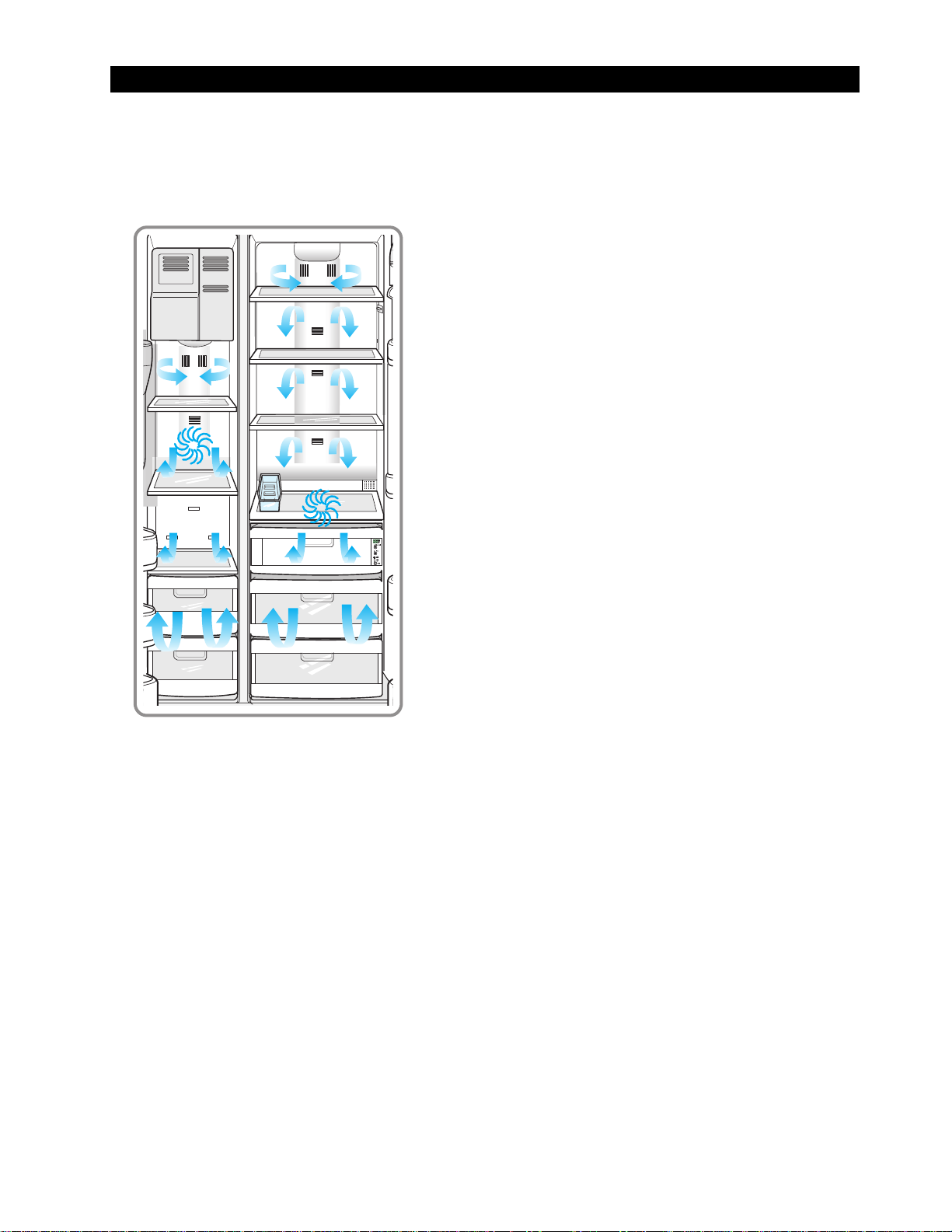
1) T win Cooling System
·The refrigerator and the freezer have two
evaporators. Given this independent system, the
freezer and the refrigerator are cooled individually as
required and are, therefore, more efficient. Food
odor from the refrigerator does not affect food in the
freezer due to separate air flow circulation.
2) Multi-Flow System
·Cool air circulates through multiple vents on every
shelf level. This provides even distribution of cooling
inside cabinets to keep your food fresh longer.
3) Xtra Space
TM
·V ertical room next to the ice maker in the freezer
provides space for pizza etc.
4) Door Alarm
·Beep sound reminds you the door is open.
5) Xtra Fresh
TM
·Optimized humidity control keeps vegetables & fruits
fresh.
6) Deodorizer
·Reusable twin deodorizers keep the refrigerator air
fresh and odor free.
7) CoolSelect Zone
TM
Drawer(RS2555, RS2577)
·User can select Quick Cool, Thaw and Select buttons
for quickly chill, thaw and cool items. Select Soft
freeze,Chill, and Cool to control the temperature of
the drawer.
5
2. INSTALLATION
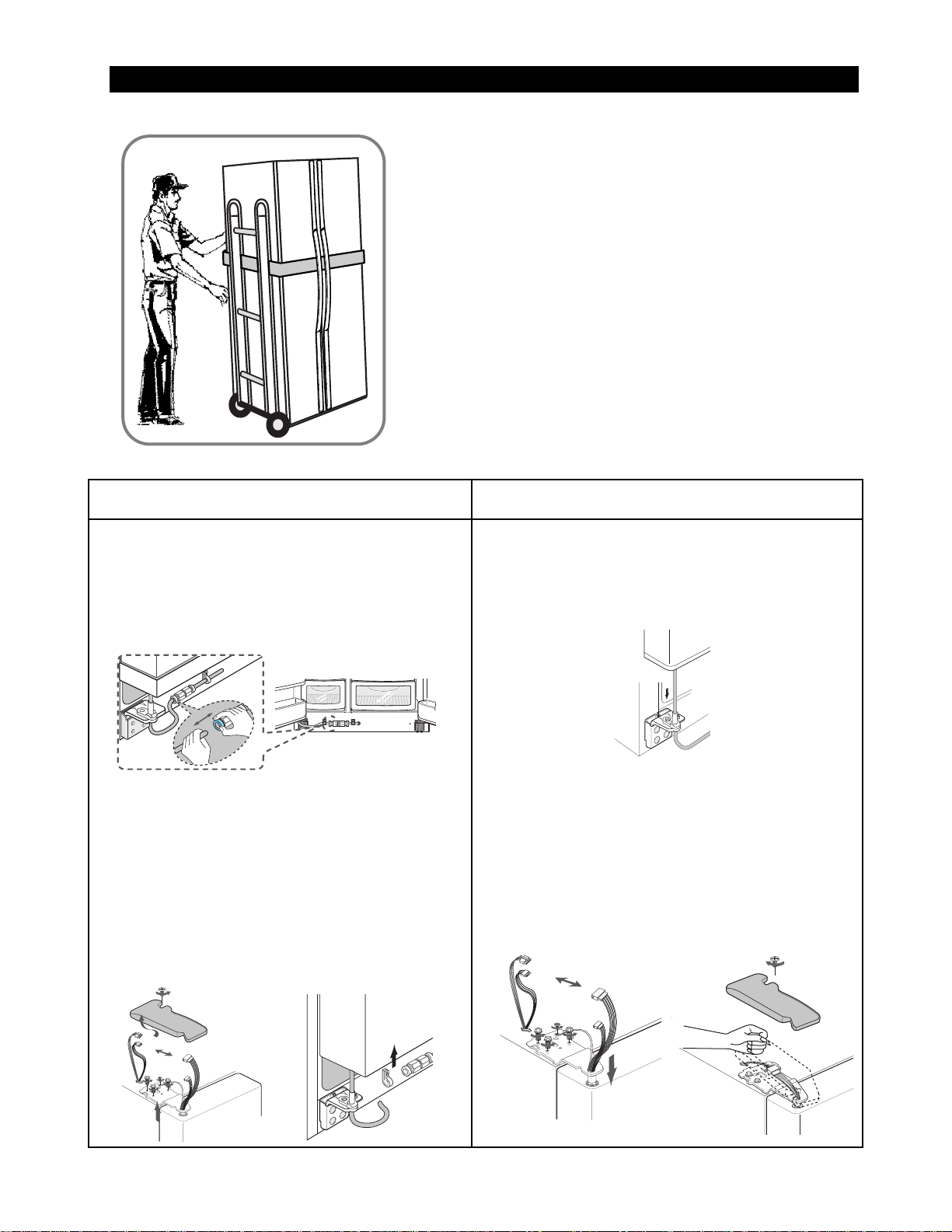
1) T o protect refrigerator in movement
Use padded hand truck as shown. If entrance width is
less than 39〃, remove doors prior to installation and
reattach doors according to procedure below.
2) Remove all protective tape and pad in refrigerators.
Connect water lines and power cord. Adjust the
clearance between the doors.
3) Set the temperature control to the temperature and
wait for an hour.
The refrigerator should get slightly chilled and the motor
runs smoothly .
4) Once the refrigerator temperature is sufficiently low
You can store food in the refrigerator. After starting the
refrigerator, it takes a few hours to reach the appropriate
temperature.
●●
Removing Doors
Open the freezer and refrigerator doors, and
then take off the front leg cover assembly by
turning the three screws counter-clockwise.
Remove the screw from clamp disconnect, the
water tube by pressing the coupler, and pulling
the water tube away .
With the door closed, remove the upper hinge
cover using a screwdriver, and then disconnect
the wires. Remove hinge screws and ground
screw counter-clockwise, and take off the upper
hinge. Take care removing the door to ensure that
it does not fall on you.
Remove the door from the lower hinge by
carefully lifting the door so as not to damage the
water tube. Remove the lower hinge from the
lower hinge bracket by lifting the lower hinge.
●●
Attaching Doors
Insert the lower hinge in the bracket lower
hinge. Attach the freezer door by inserting the
hose in the lower side of the door into the hole in
the lower hinge and pulling the hose down.
Insert the upper hinge shaft into the hole. After
leveling between the upper hinge hole and the
hole of the cabinet. Reattach hinge screws and
screw in the clockwise direction. Connect the
wires. Put the front part of the upper hinge cover
on the front part of the upper hinge and reattach
from the front part of the upper hinge cover first.
6
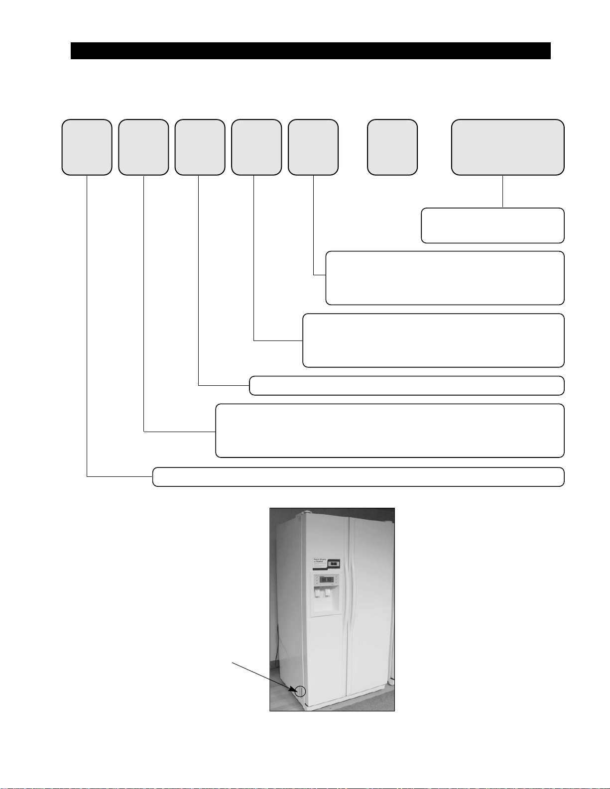
3. Nomenclature
2002 Models
R S 25 44 SW / XAA
Product ; R - REFRIGERATOR
Capacity ; CU. FT
Family ; S - SIDE BY SIDE (SBS)
H - HomePAD
TM
(SIDE BY SIDE)
B - BOTTOM MOUNTED FREEZER (BMF)
OPTION ; 25 Cu.ft 44-GOOD
26 Cu.ft 22-GOOD 44-BETTER 66-BEST
27 Cu.ft 77-BEST
COLOR ; SBS SW-SNOW WHITE SL-NOBLE STAIN
BMF SW-SNOW WHITE SL-NOBLE GRAY
Company Name
Label Location
4. Specifications
Defrost Control From 24 to 32 hrs
Thermo-Bimetal 54℉(off)/23℉(on)
Defrost Thermistor(502AT) 50℉(off)
Electrical Rating AC115V 60Hz, 4.8 Amps
Maximum Current Leakage 0.25 mA
Maximum Ground Path Resistance 0.1 Ohm
Energy Consumption KWH/mo.
Ambient Temperature 70
℉ 90℉
Refrigerator, ℉ 34∼46 34∼46
Freezer,℉ -14∼8 -14∼8
Run Time,% 40 60
Refrigerant Charge (R134a) 7.76 oz
Compressor(MK183C-L2U) 532.3 Btu/hr
Compressor oil Freol α-15
Capillary tube(Dia, Length)
0.033"",130
""
Dryer
Molecular Sieve XH-9
Clearance must be provided for air circulation
AT TOP 1
""
AT SIDES 0.1
""
AT REAR 1
""
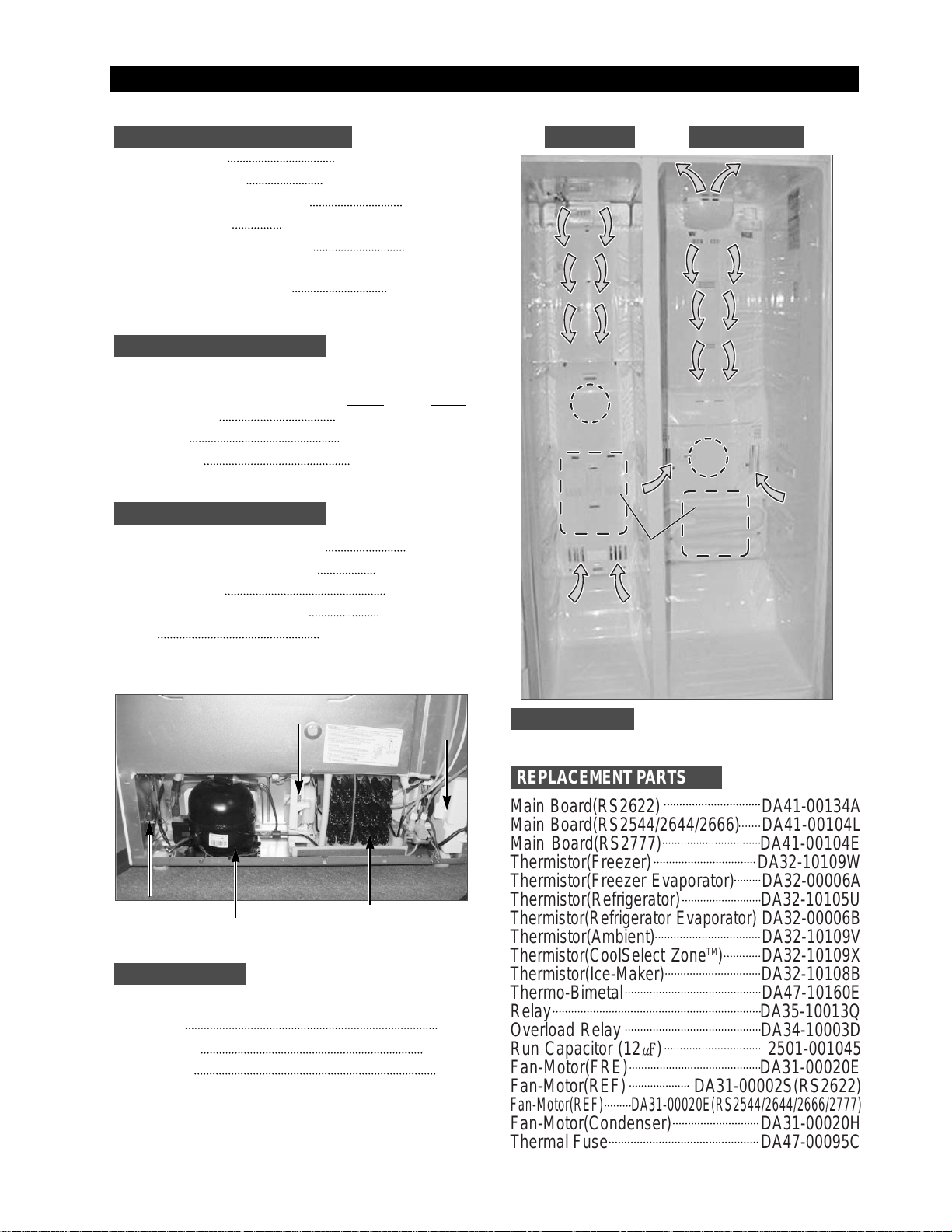
RS2544, RS2622, RS2644, RS2666, RS2777
Main Board(RS2622) DA41-00134A
Main Board(RS2544/2644/2666) DA41-00104L
Main Board(RS2777) DA41-00104E
Thermistor(Freezer) DA32-10109W
Thermistor(Freezer Evaporator) DA32-00006A
Thermistor(Refrigerator) DA32-10105U
Thermistor(Refrigerator Evaporator)
DA32-00006B
Thermistor(Ambient) DA32-10109V
Thermistor(CoolSelect ZoneTM)
DA32-10109X
Thermistor(Ice-Maker)
DA32-10108B
Thermo-Bimetal DA47-10160E
Relay DA35-10013Q
Overload Relay DA34-10003D
Run Capacitor (12㎌) 2501-001045
Fan-Motor(FRE) DA31-00020E
Fan-Motor(REF) DA31-00002S(RS2622)
Fan-Motor(REF) DA31-00020E(RS2544/2644/2666/2777)
Fan-Motor(Condenser) DA31-00020H
Thermal Fuse DA47-00095C
Fan
Fan
(Air inlet)
(Air inlet)
Heat exchanger
Compressor
Dryer
C-Fan
Electric box
Sub-condenser
ELECTRICAL SPECIFICA TIONS Freezer Refrigerator
NO LOAD PERFORMANCE
REFRIGERA TION SYSTEM
INST ALLATION
MODELS
REPLACEMENT P ARTS
7
Fan
Fan
Fan
Heat exchanger
Heat exchangerHeat exchanger
(Air inlet)
(Air inlet)
Fan
(Air inlet)
(Air inlet)
8
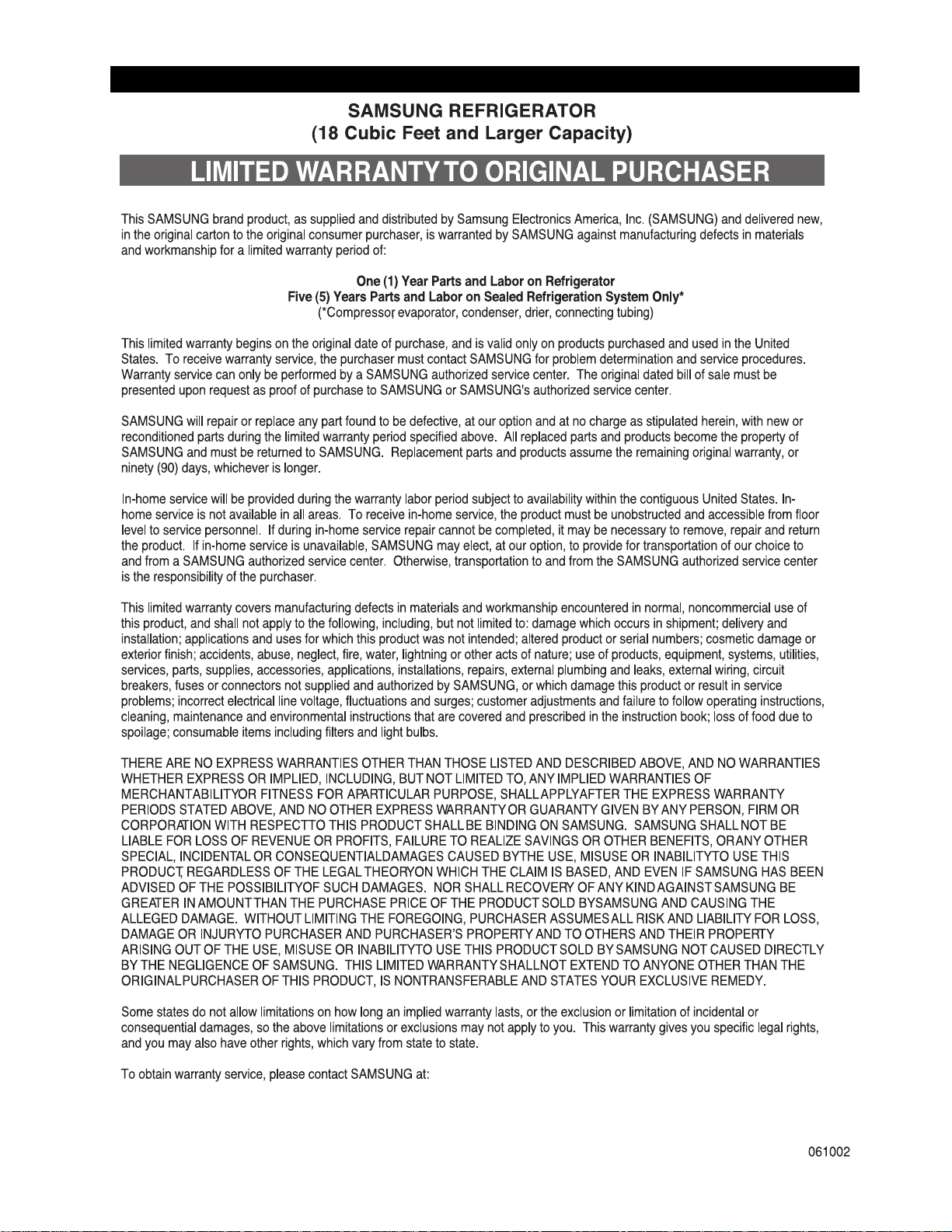
5. Warranty information
9
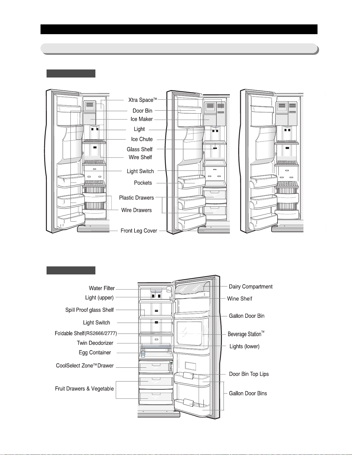
6. Interior Views and Dimensions
TM
RS2644 Model
with CoolSelectZone
TM
6-1) Shelves and Bins
Freezer
Refrigerator
S2544/2622 Model S2777/2666 Model
Chilled Bin)(RS2777)
ith CoolSelectZone
RS2666/2777)
RS2666/2777)
RS2644/2666/2777)
10
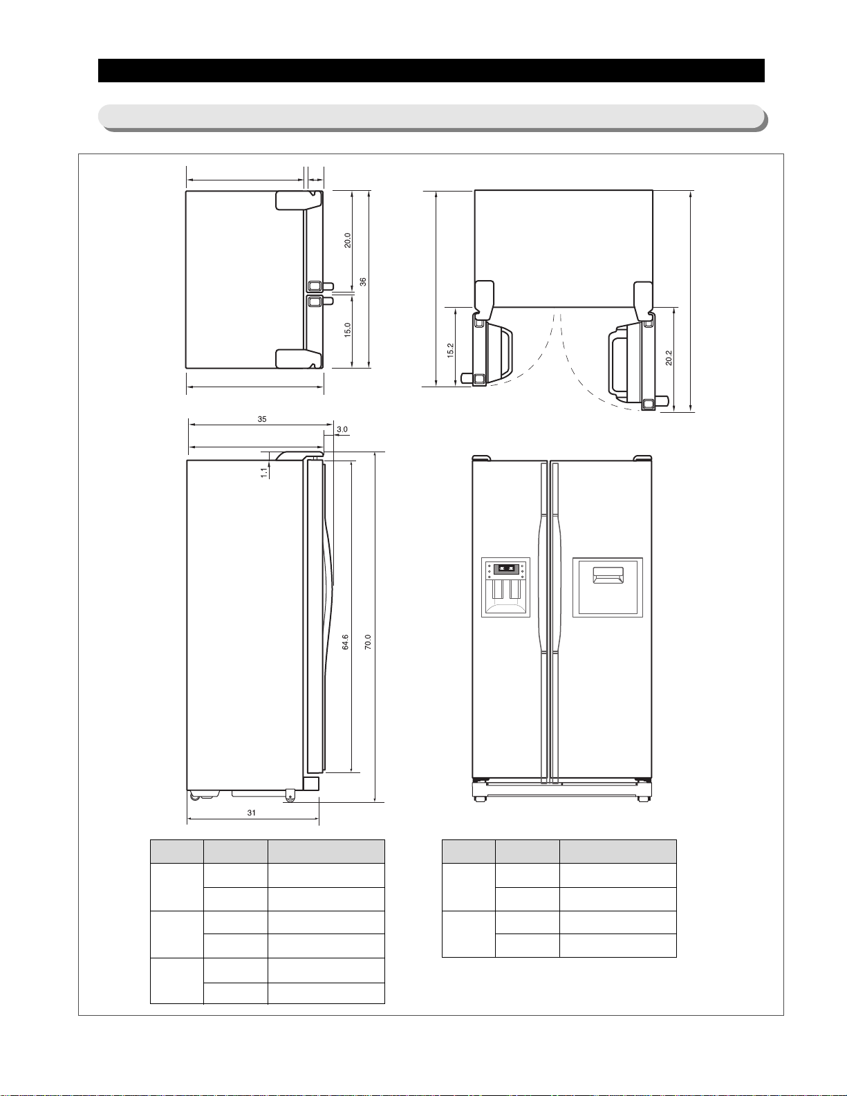
Interior Views and Dimensions
6-2) Dimensions of Refrigerator (Inches)
Beverage Station
TM
(RS2666/RS2777)
- Dimensions Model
A
B
C
28
30
35
37
1.97
3.35
RS2544
RS2622/2644/2666/2777
RS2544
RS2622/2644/2666/2777
RS2622/2644/2666
RS2544/2777
- Dimensions Model
D
E
47.2
49.2
54.2
56.3
RS2544
RS2622/2644/2666/2777
RS2544
RS2622/2644/2666/2777
A
B
C
D
D
E
11
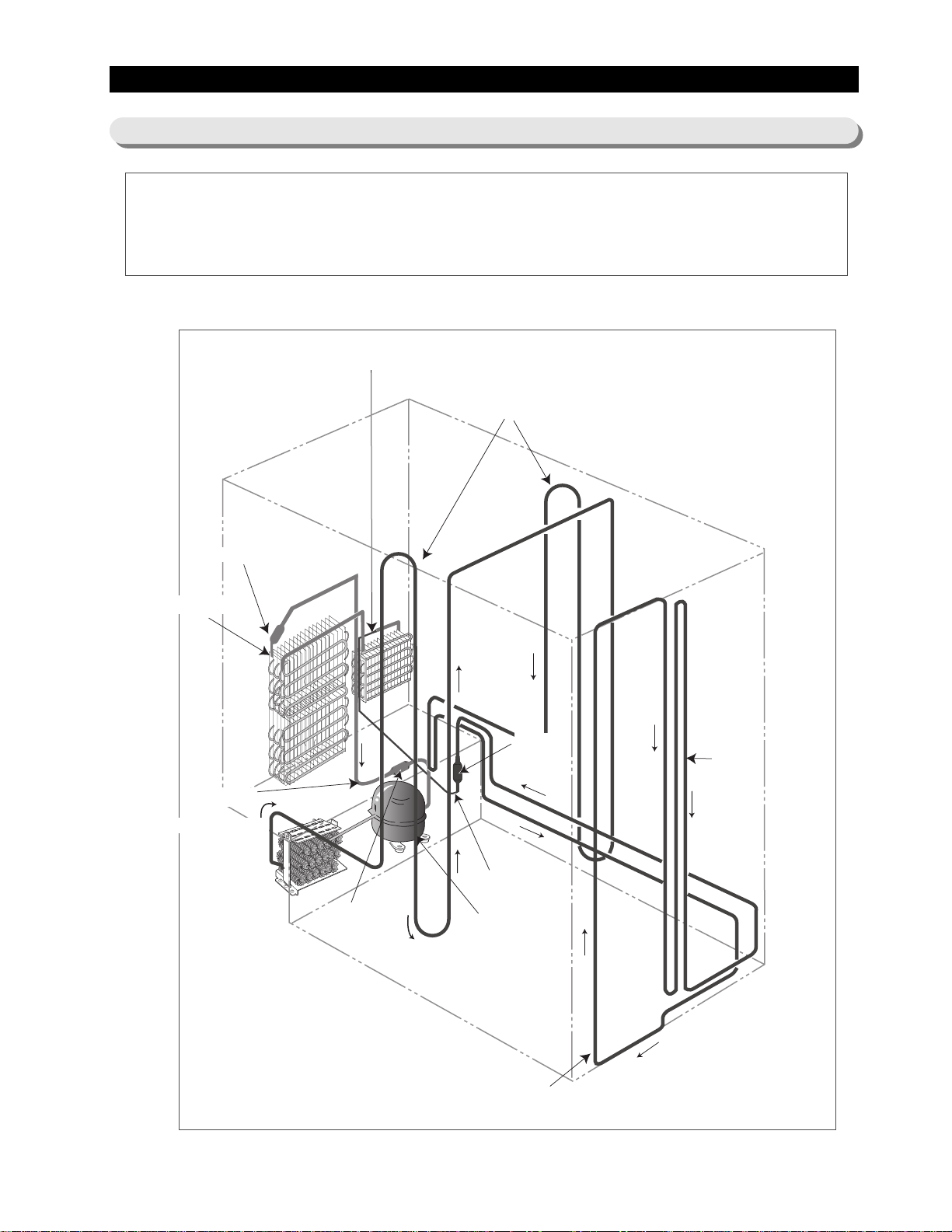
Compressor → Sub-condenser → Side Cluster Pipe(FRE) → Side Cluster Pipe(REF) → Hot Pipe
→ Dryer → Capillary Tube → Refrigerator Evaporator → Freezer Evaporator→ Suction Pipe →
Compressor
Refrigerator Evaporator
Capillary Tube
ACCUMULATOR
Freezer Evaporator
SUCTION PIPE
Dryer
Muffler
SUB-CONDENSER
Hot Pipe
Hot Pipe
Compressor
SIDE CLUSTER PIPE
7. Refrigeration Cycle and Cool Air Circulation Route
7-1) Refrigerant Route in Refrigeration cycle
12
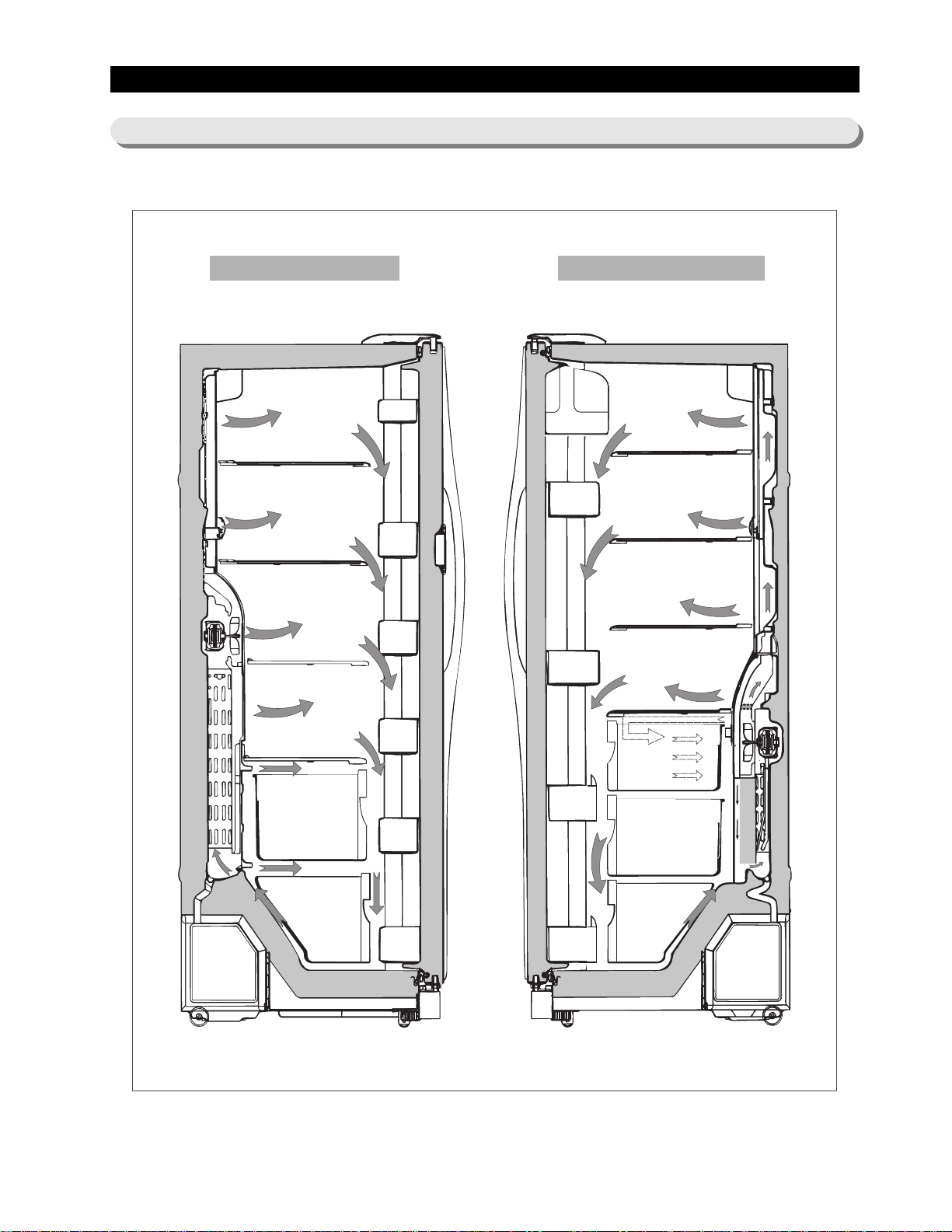
Refrigeration Cycle and Cool Air Circulation Route
7-2) Cool Air Circulation
Freezer
Refrigerator
13
8-1) Refrigerator Disassembly
8-2) Freezer Disassembly
8-3) Machine Compartment Disassembly
8. Mechanical Disassembly
Control Panel
········································
14
Door Handle
········································
14
Beverage Station
TM
·····································
14
Door Gasket
·········································
14
Refrigerator Door Light Switch
······························
15
Refrigerator Light
······································
15
Tempered Glass Shelf
···································
15
Plastic Drawers in Refrigerator
······························
15
Gallon Door Bin
·······································
15
Water Filter
·········································
16
Evaporator Cover in the Refrigerator
··························
16
Upper Ductwork
······································
16
Evaporator Fan Motor
···································
16
Evaporator in Refrigerator
·································
17
Refrigerator Thermistor
··································
17
CoolSelect Zone
TM
Thermistor
······························
17
Door Bin in Freezer
····································
18
Freezer Door Light Switch
································
18
Plastic(Wire) Drawer in Freezer
······························
18
Freezer Shelf
········································
18
Ice Dispenser & Ice Maker
································
18
Auger Motor Case
·····································
19
Freezer Light
········································
20
Evaporator Cover in Freezer
·······························
20
Upper Ductwork
·······································
20
Evaporator Fan Motor
···································
20
Evaporator in Freezer
···································
21
Freezer Thermistor
·····································
21
Ambient Thermistor
·····································
21
Ice-Maker Thermistor
····································
21
Machine Compartment & Electrix Box
··························
22
Water Solenoids
······································
22
Condenser Fan
·······································
22
Sub-condenser
·······································
22

14
88.. MMeecchhaanniiccaall DDiissaasssseemmbbllyy
1. Insert a flat-blade screwdriver on the slot as shown,
and unlock the tabs.
2. Disconnect the wire connector in the back of control
panel.
The door handles allow access into the refrigerator
and freezer. They are front mounted with Phillips
head screws.
1. With a small flat-blade screwdriver, press the
small button and pull handle cover out.
2. Remove the Phillips screws (8).
3. Lift the handle with an in and upward motion until
it disengages the locking tabs. Pull the handle
outward to remove it.
The beverage station
TM
allows access to the
refrigerator without opening the refrigerator door.
1. Open the door beverage station
TM
2. With a small flat-blade screwdriver,take out the
rubbercap, then put it into the small hole and
push the button inside.
3. Take off its door.
The door gasket is a molded gasket set into a
channel located in the door liner.
1. Open the door.
2. Grasp the gasket and pull in an outward motion
until the molded gasket separates from the door
liner.
Control Panel
Door Handle
Beverage Station
TM
Door Gasket
Button
8-1) Refrigerator Disassembly

15
MMeecchhaanniiccaall DDiissaasssseemmbbllyy
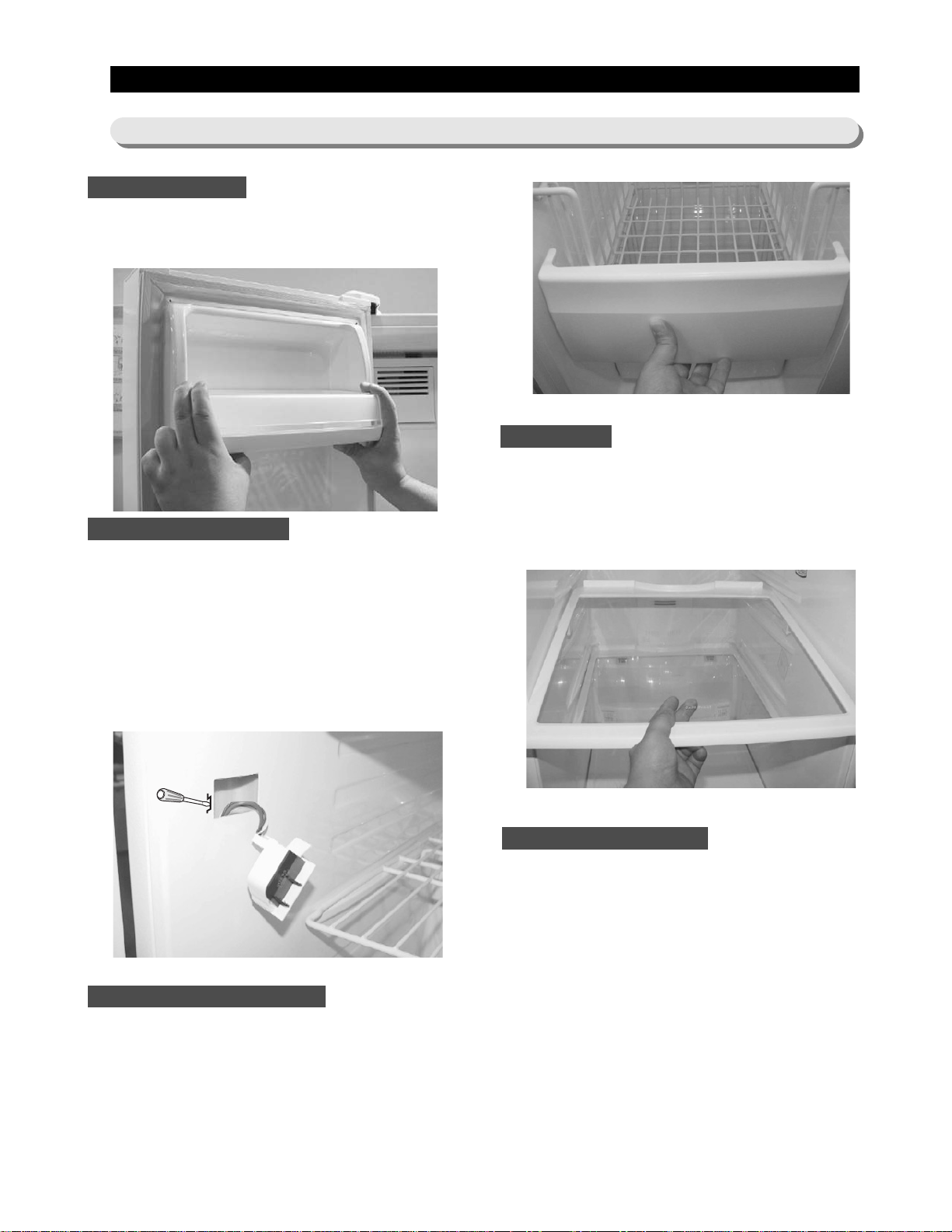
The refrigerator has a door light switch located in
the upper right corner for the refrigerator.
1. Use a small flat-blade screwdriver to unlock the
locking tab and pull the switch out until the
wire connector is visible.
The refrigerator lights are located in the upper and
lower portion of refrigerator.
1. Pull out the screw cap and remove the screw.
2. To access the lower lights, pull out the screw cap
and remove the screw.
3. Remove the lamp cover by unlocking the tabs
and pulling the cover down.
These shelves allow the storage of larger items and
pull out for easy access.
1. Pull the shelf out as for as it goes.
2. Lift it up and remove it.
Drawers are designed for storage of fruits,
vegetables, and deli items. The drawers are located
in the lower portion of the refrigerator.
1. Pull out the drawer as far as it goes.
2. Tilt the drawer up and pull it out until it is
removed.
The door bins allow storage of perishable items.
1. Push the bin up and slide it out.
Refrigerator Door Light Switch
Gallon Door Bin
T empered Glass Shelf
Plastic Drawers in Refrigerator
Refrigerator Light
16
MMeecchhaanniiccaall DDiissaasssseemmbbllyy
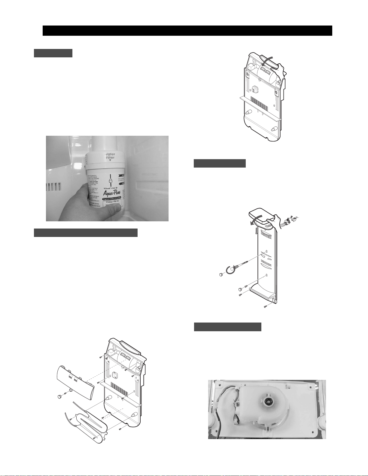
The water filter is located in the upper right-hand
corner of the refrigerator. The water filter filters water
for the ice maker and the water dispenser.
1. Turn the water filter 1/2 turn counterclockwise and
pull it down.
2. To install the filter, align the indication mark
(unlock position) and push it up while turning 1/2
turn clockwise until the lock position is aligned.
Do not over tighten.
1. Pull out the screw cap and remove the screw.
2. Remove the lamp cover by unlocking the tabs
and pulling the cover down.
3. Remove the water tank from the evaporator cover
by unscrewing the screws (2).
4. Remove the screws (6) at the evaporator cover
and the two fixed screws of the wire connector
cover.
5. Take off motor and lamp wire connector located
on the upper liner.
6. Remove the duckwork of the evaporator fan in the
direction of the arrow as shown.
1. Remove the screw caps (2) and screws (5).
2. Slide the upper fan ductwork out while
disconnecting the wire connector(lamp and
thermistor).
The evaporator fan is located in the middle rear of
the freezer. This fan circulates cold air in the freezer.
1. Remove screws (4) located at the four corners of
the fan bracket.
2. Take the fan motor assembly off.
Water Filter
Evaporator Cover in the Refrigerator
Upper Ductwork
Evaporator Fan Motor
17
MMeecchhaanniiccaall DDiissaasssseemmbbllyy
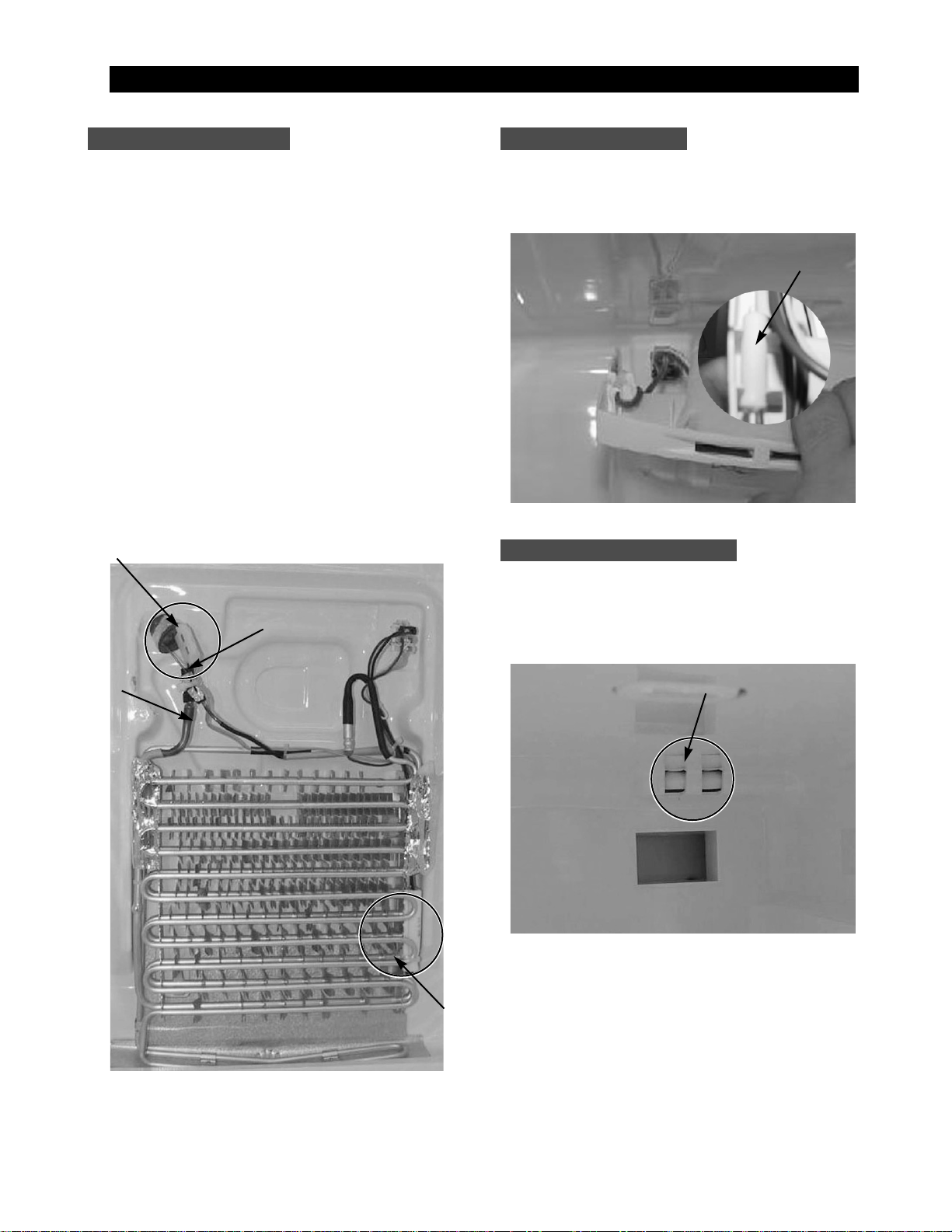
Evaporator is located in the bottom of refrigerator.
1. Take off the ductwork in refrigerator.
2. Disconnect the wire connector.(Heater and
Thermistor)
3. Desolder the capillary tube and the suction line
from the evaporator.
4. Remove the evaporator.
5. With a file, score the capillary tube just upstream
of the soldered point. Break off the soldered
section to help prevent solder from plugging the
tube during soldering.
6. Place a new evaporator and braze the suction
and capillary tube to evaporator using silver
solder.
7. Install a replacement dryer.
8. Evacuate and recharge the system using
reasonable procedures.
The refrigerator thermistor is located inside of the
upper light cover of the refrigerator.
The CoolSelect Zone
TM
thermistor is located outside
the back of CoolSelect Zone
TM
drawer. The
temperature signal goes to the micro-processor.
Refrigerator ThermistorRefrigerator Thermistor
CoolSelect ZoneTMThermistor
Thermistor
Thermistor
CoolSelect ZoneTMThermistor
Suction Line
Capillary Tube
Thermal Fuse
Evaporator in Refrigerator
18
The door bins allow storage of perishable items.
1. Push the bin up and slide it out.
This switch is located in the left-hand portion of the
freezer and sends a signal to the processor.
1. With a small flat-blade screwdriver, unlock the
locking tabs and pull the switch out until the wire
connector is visible.
2. Disconnect the wire connector and remove the
switch.
Drawers are designed for storage of meat and dry
foods. The drawers are located in the lower portion of
the freezer.
1. Pull out the drawer as far as it goes.
2. Tilt the drawer up and pull it out until it is
removed.
The shelves slide out for easy access for frozen
items.
1. Slide the shelf out until it reaches its stop.
2. Tilt down and slide it out of thecompartment.
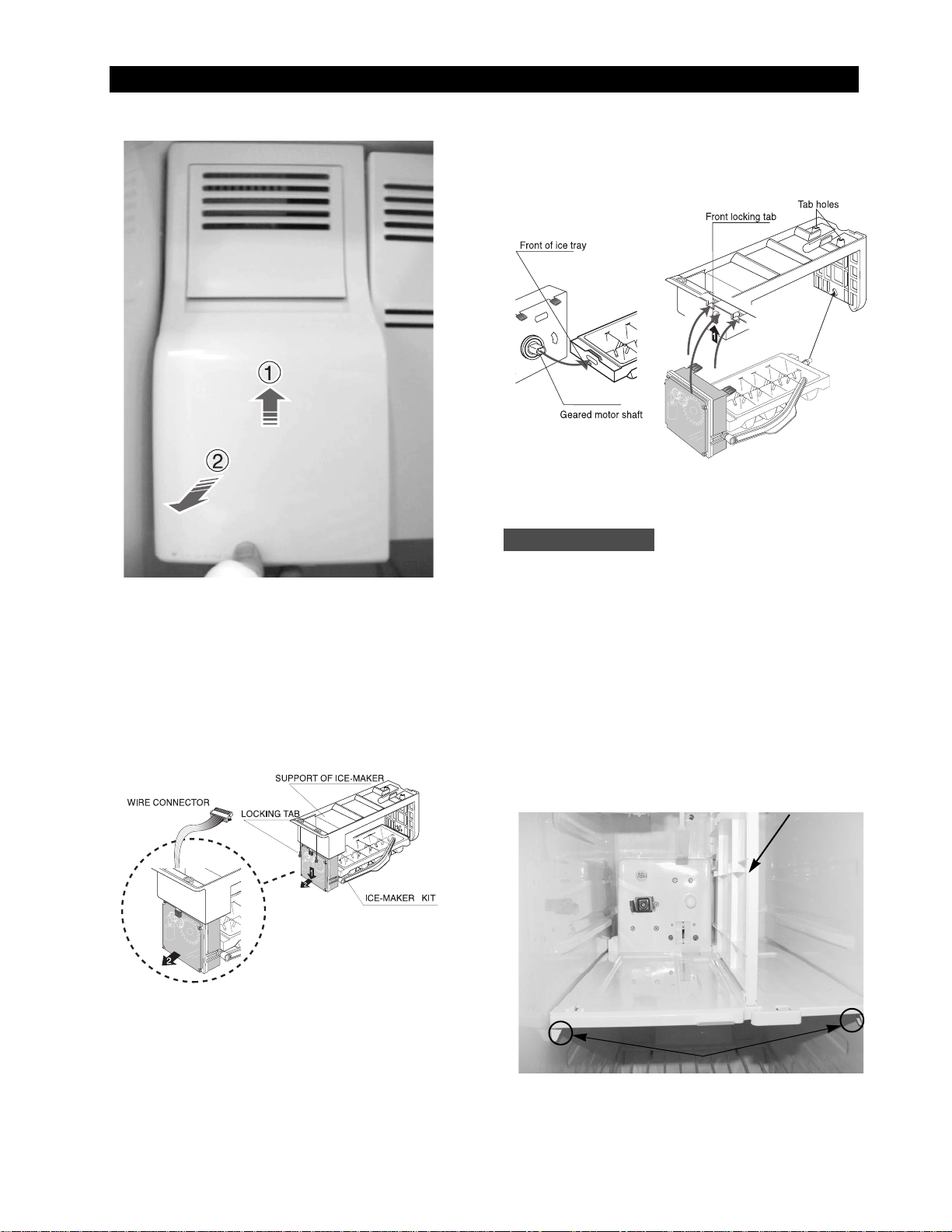
The ice dispenser is located in the upper portion of
the freezer. This assembly stores ice made by the
icemaker and dispenses ice.
1. Lift the ice bucket up ① and slide out the ice
dispenser assembly ②.
Door Bin in Freezer
MMeecchhaanniiccaall DDiissaasssseemmbbllyy
8-2) Freezer Disassembly
Freezer Shelf
Plastic (Wire) Drawer in Freezer
Freezer Door Light Switch
19
MMeecchhaanniiccaall DDiissaasssseemmbbllyy
The ice maker is located inside of the ice dispenser
assembly.
1.
Remove ice maker support screws (2), and slide out.
2. Disconnect the ice maker wire connector.
3.
Unlock the locking tabs to separate the ice maker kit.
In order to assemble the icemaker kit.
1. Assemble the geared motor shaft and the front of
ice tray.
2. Lift the front locking tab and assemble the ice
maker kit.
3. Connect the ice maker wire connector.
4. Match the tab holes and tabs(2) located on the
top of the liner, and slide the ice maker in.
5. Tighten the screws (2) of the ice maker support.
This shelf is designed to support the ice maker &
ice dispensed and Xtra Space
TM
.
1. Remove the Xtra Space
TM
cover to push it down
near the partition.
2. Slide the partition out.
3. Remove the screws (2) on the bottom front of the
case.
4. Slide out the case while disconnecting the wire
connect.
Auger Motor Case
Partition
Screws

20
The freezer light is located in the bottom of the
auger motor case. The light is covered by an opaque
cover.
1. Remove the screw and the light cover.
1. Pull out the screw caps and remove screws (6).
2. Remove the ductwork of the evaporator fan in the
direction of the arrow as shown.
3. Disconnect the wire connector.
1. Remove the screw cap and screw.
2. Slide the upper fan ductwork out while
disconnecting the wire connector (Lamp and
Thermistor).
The evaporator fan is located in the lower rear of
refrigerator. This fan circulates cold air in the
refrigerator.
1. Remove screw(4) located at the four corners of
the fan bracket.
2. Take the fan motor assembly off.
Upper Ductwork
Evaporator Fan Motor
Freezer Light
Evaporator Cover in Freezer
MMeecchhaanniiccaall DDiissaasssseemmbbllyy
 Loading...