


Samsung RS2511, RS2630W-XAA, RS2611, RS2631, RS2630SW User Manual
...
SIDE-BY-SIDE REFRIGERATOR
SAMSUNG Home Appliance Service
MODEL:
RS2511
RS2611
RS2630W/XAA
RS2531
RS2631
RS2521
RS2621
RS2630SW

2
IMPORTANT SAFETY NOTICE
The service guide is for service men with adequate backgrounds of
electrical, electronic, and mechanical experience. Any attempt to repair
a major appliance may result in personal injury and property damage.
The manufacturer or dealer cannot be responsible for the interpretation
of this information.
SAMSUNG ELECTRONICS AMERICA, INC.
Technical Service Guide
Copyright ⓒ2004
All rights reserved. This service guide may not be reproduced in whole or in
part in any form without written per mission from the SAMSUNG ELECTRONICS
Company.
WARNING

3
Contents
9. Specifications 32
10. Interior Views and Dimensions 33
11. Refrigeration Cycle and Cool Air Circulation Route 36
12. Function & How- to-use By Products 38
13. Diagnostics 58
1. Safety instruction on services
2. Warranty information
∙∙∙∙∙∙∙∙∙∙∙∙∙∙∙∙∙∙∙∙∙∙∙∙∙∙∙∙∙∙∙∙∙∙∙
3. Mechanical Disassembly
4.
Circuit Diagram
5.
Operation Principles By Parts Of Circuit
∙∙∙∙∙∙∙∙∙∙∙∙∙∙∙∙∙∙∙∙∙∙∙∙∙∙∙∙∙∙∙∙∙∙∙∙∙∙
6.Introduction
∙∙∙∙∙∙∙∙∙∙∙∙∙∙∙∙∙∙∙∙∙∙∙∙∙∙∙∙∙∙
4
9
∙∙∙∙∙∙∙∙∙∙∙∙∙∙∙∙∙∙∙∙∙∙∙∙∙∙∙∙∙∙∙∙
14
15
∙∙∙∙∙∙∙∙∙∙∙∙∙∙∙∙∙∙∙∙∙∙∙∙
∙∙∙∙∙∙∙∙∙∙∙∙∙∙∙∙∙∙∙∙∙∙∙∙∙∙∙∙∙∙∙∙∙
16
29
7. Installation 30
8. Nomenclature 31

1. Safety Instructions on Service
Unplug the refrigerator before making any repair or any replacement.
Avoid the electric shock.
Use the rated components on the replacement.
Check the correct model number, rated voltage, rated current, operating temperature and so
on.
On repair, be sure that the wires such as harness are bundled tightly and are not exposed by
water
Bundle wires tightly in order not to be detached by the external force.
On repair, remove completely dust, particles or other things on housing parts, harness parts,
and connectors.
Cleaning may prevent fire by tracking or short.
Check if there is any trace indicating the infitration of water on electrical parts.
If there is kind of trace, change the related components or do the necessary action
such as taping using the insulating tape.
After repair, check the assembled state of parts.
It must be in the same assembled state when compared with the state before
disassembly.
Check the surrounding conditions of the installed refrigerator.
When the refrigerator is located at humid or wet place, or the installed state is
unstable, change the location.
If needed, do the ground.
Especially, if there is a possibility of the electric leakage, this appliance must be
properly grounded.
Do not allow consumers to use one outlet for several plugs.
Check whether the power cord is placed under other appliance and so, damaged, worm-out
squeezed.
Repair immediately the defective power plug or outlet.
Make sure that the power cord is not placed under other appliance or squeezed.
Do not allow consumers to keep bottles or the likes in the Freezer or to keep foods in unstable
position.
Do not allow consumers to repair the appliance by themselves.
Do not allow consumers to keep other chemicals except food.
Medicines and other materials for research ; This appliance will not maintain the precisely
constant temperature for them.
Volatile material(Alcohol, Benzene, Ether, LP gas etc.) : possibility of explosion
4

5
2. Warranty information
LIMITED WARRANTY TO ORIGINAL PURCHASER
SAMSUNG REFRIGERATOR
This SAMSUNG brand product, as supplied and distributed by Samsung Electronics America, Inc. (SAMSUNG) and delivered new,
in the original carton to the original consumer purchaser, is warranted by SAMSUNG against manufacturing defects in materials
and workmanship for a limited warranty period of:
One (1) Year Parts and Labor on Refrigerator
Five (5) Years Parts and Labor on Sealed Refrigeration System Only*
(*Compressor, evaporator, condenser, drier, connecting tubing)
This limited warranty begins on the original date of purchase, and is valid only on products purchased and used in the United
States. To receive warranty service, the purchaser must contact SAMSUNG for problem determination and service procedures.
Warranty service can only be performed by a SAMSUNG authorized service center. The original dated bill of sale must be
presented upon request as proof of purchase to SAMSUNG or SAMSUNG's authorized service center.
SAMSUNG will repair or replace any part found to be defective, at our option and at no charge as stipulated herein, with new or
reconditioned parts during the limited warranty period specified above. All replaced parts and products become the property of
SAMSUNG and must be returned to SAMSUNG. Replacement parts and products assume the remaining original warranty, or
ninety (90) days, whichever is longer.
In-home service will be provided during the warranty labor period subject to availability within the contiguous United States. Inhome service is not available in all areas. To receive in-home service, the product must be unobstructed and accessible from floor
level to service personnel. If during in-home service repair cannot be completed, it may be necessary to remove, repair and return
the product. If in-home service is unavailable, SAMSUNG may elect, at our option, to provide for transportation of our choice to
and from a SAMSUNG authorized service center. Otherwise, transportation to and from the SAMSUNG authorized service center
is the responsibility of the purchaser.
This limited warranty covers manufacturing defects in materials and workmanship encountered in normal, noncommercial use of
this product, and shall not apply to the following, including, but not limited to: damage which occurs in shipment; delivery and
installation; applications and uses for which this product was not intended; altered product or serial numbers; cosmetic damage or
exterior finish; accidents, abuse, neglect, fire, water, lightning or other acts of nature; use of products, equipment, systems, utilities,
services, parts, supplies, accessories, applications, installations, repairs, external plumbing and leaks, external wiring, circuit
breakers, fuses or connectors not supplied and authorized by SAMSUNG, or which damage this product or result in service
problems; incorrect electrical line voltage, fluctuations and surges; customer adjustments and failure to follow operating instructions,
cleaning, maintenance and environmental instructions that are covered and prescribed in the instruction book; loss of food due to
spoilage; consumable items including filters and light bulbs.
THERE ARE NO EXPRESS WARRANTIES OTHER THAN THOSE LISTED AND DESCRIBED ABOVE, AND NO WARRANTIES
WHETHER EXPRESS OR IMPLIED, INCLUDING, BUT NOT LIMITED TO, ANY IMPLIED WARRANTIES OF
MERCHANTABILITY OR FITNESS FOR A PARTICULAR PURPOSE, SHALL APPLY AFTER THE EXPRESS WARRANTY
PERIODS STATED ABOVE, AND NO OTHER EXPRESS WARRANTY OR GUARANTY GIVEN BY ANY PERSON, FIRM OR
CORPORATION WITH RESPECT TO THIS PRODUCT SHALL BE BINDING ON SAMSUNG. SAMSUNG SHALL NOT BE
LIABLE FOR LOSS OF REVENUE OR PROFITS, FAILURE TO REALIZE SAVINGS OR OTHER BENEFITS, OR ANY OTHER
SPECIAL, INCIDENTAL OR CONSEQUENTIAL DAMAGES CAUSED BY THE USE, MISUSE OR INABILITY TO USE THIS
PRODUCT, REGARDLESS OF THE LEGAL THEORY ON WHICH THE CLAIM IS BASED, AND EVEN IF SAMSUNG HAS BEEN
ADVISED OF THE POSSIBILITY OF SUCH DAMAGES. NOR SHALL RECOVERY OF ANY KIND AGAINST SAMSUNG BE
GREATER IN AMOUNT THAN THE PURCHASE PRICE OF THE PRODUCT SOLD BY SAMSUNG AND CAUSING THE
ALLEGED DAMAGE. WITHOUT LIMITING THE FOREGOING, PURCHASER ASSUMES ALL RISK AND LIABILITY FOR LOSS,
DAMAGE OR INJURY TO PURCHASER AND PURCHASER’S PROPERTY AND TO OTHERS AND THEIR PROPERTY
ARISING OUT OF THE USE, MISUSE OR INABILITY TO USE THIS PRODUCT SOLD BY SAMSUNG NOT CAUSED DIRECTLY
BY THE NEGLIGENCE OF SAMSUNG. THIS LIMITED WARRANTY SHALL NOT EXTEND TO ANYONE OTHER THAN THE
ORIGINAL PURCHASER OF THIS PRODUCT, IS NONTRANSFERABLE AND STATES YOUR EXCLUSIVE REMEDY.
Some states do not allow limitations on how long an implied warranty lasts, or the exclusion or limitation of incidental or
consequential damages, so the above limitations or exclusions may not apply to you. This warranty gives you specific legal rights,
and you may also have other rights, which vary from state to state.
To obtain warranty service, please contact SAMSUNG at:
061002

6
3-1) Refrigerator Disassembly
3-2) Freezer Disassembly
3-3) Machine Compartment Disassembly
3. Mechanical Disassembly
Control Panel
∙∙∙∙∙∙∙∙∙∙∙∙∙∙∙∙∙∙∙∙∙∙∙∙∙∙∙∙∙∙∙∙∙∙∙∙∙∙∙∙
7
Door Handle
∙∙∙∙∙∙∙∙∙∙∙∙∙∙∙∙∙∙∙∙∙∙∙∙∙∙∙∙∙∙∙∙∙∙∙∙∙∙∙∙∙
7
Door Gasket
∙∙∙∙∙∙∙∙∙∙∙∙∙∙∙∙∙∙∙∙∙∙∙∙∙∙∙∙∙∙∙∙∙∙∙∙∙∙∙∙∙
7
Refrigerator Door Light Switch
∙∙∙∙∙∙∙∙∙∙∙∙∙∙∙∙∙∙∙∙∙∙∙∙∙∙∙∙∙∙∙
7
Refrigerator Light
∙∙∙∙∙∙∙∙∙∙∙∙∙∙∙∙∙∙∙∙∙∙∙∙∙∙∙∙∙∙∙∙∙∙∙∙∙∙
8
Tempered Glass Shelf
∙∙∙∙∙∙∙∙∙∙∙∙∙∙∙∙∙∙∙∙∙∙∙∙∙∙∙∙∙∙∙∙∙∙∙
8
Plastic Drawers in Refrigerator
∙∙∙∙∙∙∙∙∙∙∙∙∙∙∙∙∙∙∙∙∙∙∙∙∙∙∙∙∙∙
8
Gallon Door Bin
∙∙∙∙∙∙∙∙∙∙∙∙∙∙∙∙∙∙∙∙∙∙∙∙∙∙∙∙∙∙∙∙∙∙∙∙∙∙∙
8
Water Filter
∙∙∙∙∙∙∙∙∙∙∙∙∙∙∙∙∙∙∙∙∙∙∙∙∙∙∙∙∙∙∙∙∙∙∙∙∙∙∙∙∙
8
Damper in the Refrigerator
∙∙∙∙∙∙∙∙∙∙∙∙∙∙∙∙∙∙∙∙∙∙∙∙∙∙∙∙∙∙∙∙
9
Twin cool in the Refrigerator
∙∙∙∙∙∙∙∙∙∙∙∙∙∙∙∙∙∙∙∙∙∙∙∙∙∙∙∙∙∙∙
9
Refrigerator Thermistor
∙∙∙∙∙∙∙∙∙∙∙∙∙∙∙∙∙∙∙∙∙∙∙∙∙∙∙∙∙∙∙∙∙∙
9
Door Bin in Freezer
∙∙∙∙∙∙∙∙∙∙∙∙∙∙∙∙∙∙∙∙∙∙∙∙∙∙∙∙∙∙∙∙∙∙∙∙
10
Freezer Door Light Switch
∙∙∙∙∙∙∙∙∙∙∙∙∙∙∙∙∙∙∙∙∙∙∙∙∙∙∙∙∙∙∙∙∙
10
Plastic(Wire) Drawer in Freezer
∙∙∙∙∙∙∙∙∙∙∙∙∙∙∙∙∙∙∙∙∙∙∙∙∙∙∙∙∙∙
10
Freezer Shelf
∙∙∙∙∙∙∙∙∙∙∙∙∙∙∙∙∙∙∙∙∙∙∙∙∙∙∙∙∙∙∙∙∙∙∙∙∙∙∙∙
10
Ice Dispenser Ice Maker
∙∙∙∙∙∙∙∙∙∙∙∙∙∙∙∙∙∙∙∙∙∙∙∙∙∙∙∙∙∙∙∙
10
Auger Motor Case
∙∙∙∙∙∙∙∙∙∙∙∙∙∙∙∙∙∙∙∙∙∙∙∙∙∙∙∙∙∙∙∙∙∙∙∙∙
11
Freezer Light
∙∙∙∙∙∙∙∙∙∙∙∙∙∙∙∙∙∙∙∙∙∙∙∙∙∙∙∙∙∙∙∙∙∙∙∙∙∙∙∙
12
Evaporator Cover in Freezer
∙∙∙∙∙∙∙∙∙∙∙∙∙∙∙∙∙∙∙∙∙∙∙∙∙∙∙∙∙∙∙∙
12
Evaporator Fan Motor
∙∙∙∙∙∙∙∙∙∙∙∙∙∙∙∙∙∙∙∙∙∙∙∙∙∙∙∙∙∙∙∙∙∙∙
12
Evaporator in Freezer
∙∙∙∙∙∙∙∙∙∙∙∙∙∙∙∙∙∙∙∙∙∙∙∙∙∙∙∙∙∙∙∙∙∙∙
13
Freezer Thermistor
∙∙∙∙∙∙∙∙∙∙∙∙∙∙∙∙∙∙∙∙∙∙∙∙∙∙∙∙∙∙∙∙∙∙∙∙∙
13
Ambient Thermistor
∙∙∙∙∙∙∙∙∙∙∙∙∙∙∙∙∙∙∙∙∙∙∙∙∙∙∙∙∙∙∙∙∙∙∙∙∙
13
Ice-Maker Thermistor
∙∙∙∙∙∙∙∙∙∙∙∙∙∙∙∙∙∙∙∙∙∙∙∙∙∙∙∙∙∙∙∙∙∙∙∙
13
Machine Compartment Electrix Box
∙∙∙∙∙∙∙∙∙∙∙∙∙∙∙∙∙∙∙∙∙∙∙∙∙∙
14
Water Solenoids
∙∙∙∙∙∙∙∙∙∙∙∙∙∙∙∙∙∙∙∙∙∙∙∙∙∙∙∙∙∙∙∙∙∙∙∙∙∙
14
Condenser Fan
∙∙∙∙∙∙∙∙∙∙∙∙∙∙∙∙∙∙∙∙∙∙∙∙∙∙∙∙∙∙∙∙∙∙∙∙∙∙∙
14
Sub-condenser
∙∙∙∙∙∙∙∙∙∙∙∙∙∙∙∙∙∙∙∙∙∙∙∙∙∙∙∙∙∙∙∙∙∙∙∙∙∙∙
14
7
3. Mechanical Disassembly
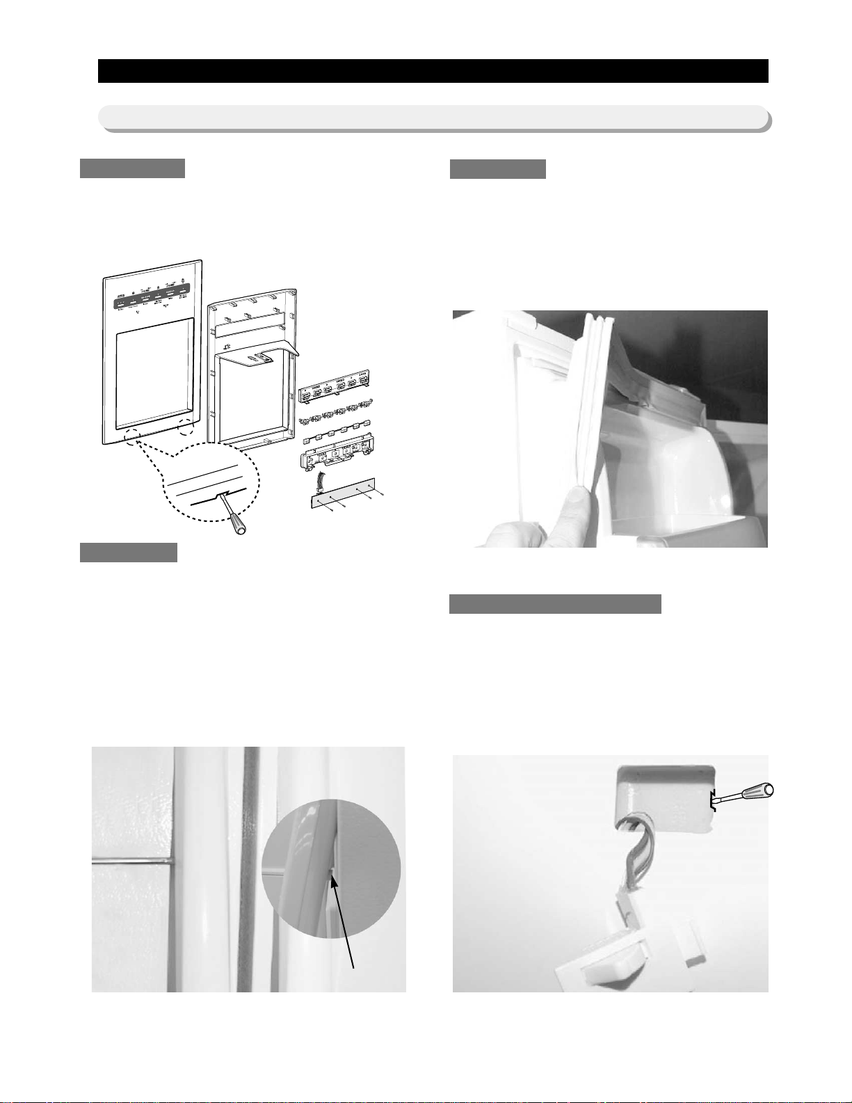
1. Insert a flat-blade screwdriver on the slot as shown,
and unlock the tabs.
2. Disconnect the wire connector.
The door handles allow access into the refrigerator
and freezer. They are front mounted with Phillips
head screws.
1. With a small flat-blade screwdriver, press the
small button and pull handle cover out.
2. Remove the Phillips screws (5).
3. Lift the handle with an in and upward motion until
it disengages the locking tabs. Pull the handle
outward to remove it.
The door gasket is a molded gasket set into a
channel located in the door liner.
1. Open the door.
2. Grasp the gasket and pull in an outward motion
until the molded gasket separates from the door
liner.
The refrigerator has a door light switch located in
the upper right corner for the refrigerator.
1. Use a small flat-blade screwdriver to unlock the
locking tab and pull the switch out until the
wire connector is visible.
Control Panel
Door Handle
Door Gasket
3-1) Refrigerator Disassembly
Refrigerator Door Light Switch
Button
8
Mechanical Disassembly
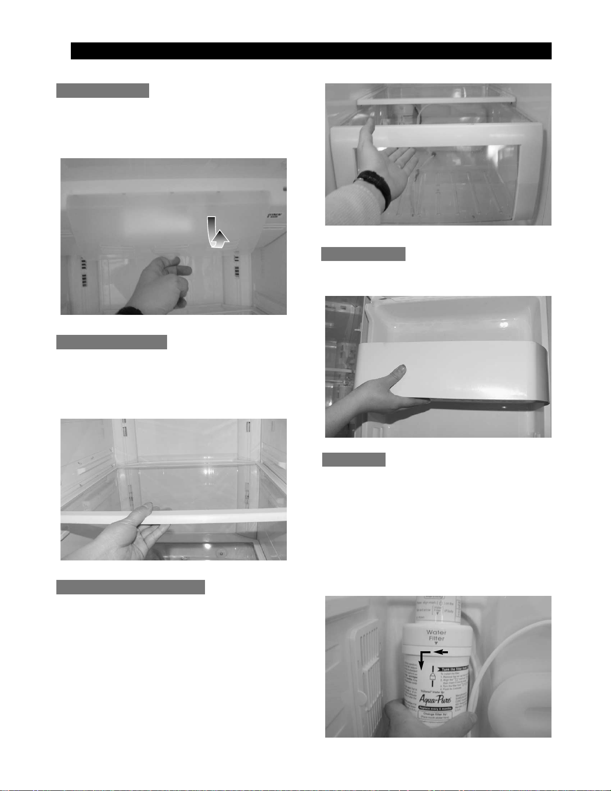
The refrigerator light is located in the upper portion
of refrigerator.
1. Pull the tip on the cover.
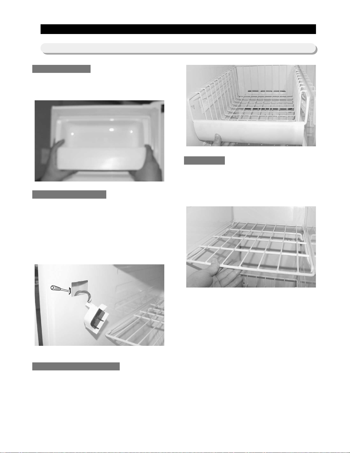
These shelves allow the storage of larger items and
pull out for easy access.
1. Pull the shelf out as far as it goes.
2. Lift it up and remove it.
Drawers are designed for storage of fruits,
vegetables, and deli items. The drawers are located
in the lower portion of the refrigerator.
1. Pull out the drawer as far as it goes.
2. Tilt the drawer up and pull it out until it is
removed.
The door bins allow storage of perishable items.
1. Push the bin up and slide it out.
The water filter is located in the bottom left-hand
corner of the refrigerator. The water filter filters water
for the ice maker and the water dispenser.
1. Turn the water filter 1/2 turn counterclockwise and
pull it down.
2. To install the filter, align the indication mark
(unlock position) and push it up while turning 1/2
turn clockwise until the lock position is aligned.
Do not over tighten.
Gallon Door Bin
T empered Glass Shelf
Plastic Drawers in Refrigerator
Refrigerator Light
Water Filter
9
Mechanical Disassembly
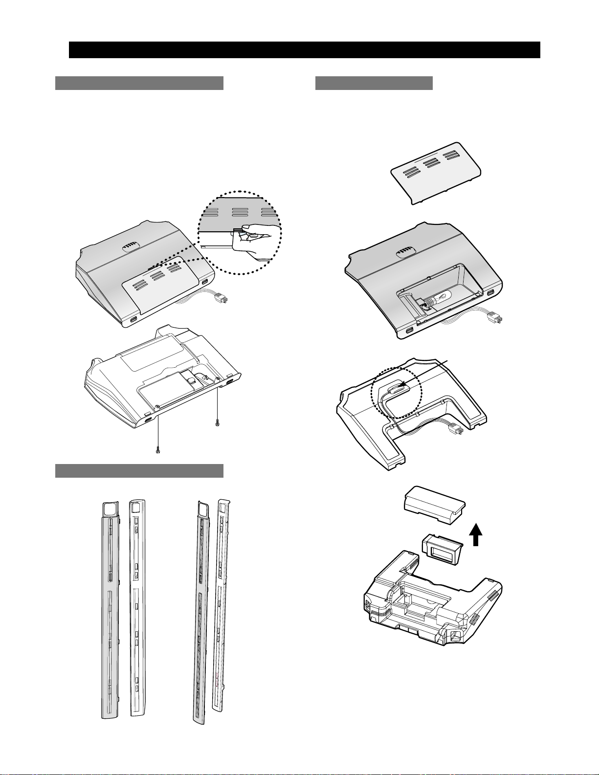
Damper in the Refrigerator
1. Pull out the screw cap and remove the screw.
2. Remove the lamp cover by unlocking the tabs
and pulling the cover down.
3. Remove the screw at the cover damper.
4. Take off sensor and lamp wire connector located
on the upper liner.
6. Remove the damper from the refrigerator.
1. Pull out the Twin cool by unlocking the hooks.
The refrigerator thermistor is located inside of the
upper light cover of the refrigerator.
T win cool in the Refrigerator
Refrigerator Thermistor
THERMISTOR
10
The door bins allow storage of perishable items.
1. Push the bin up and slide it out.
This switch is located in the left-hand portion of the
freezer and sends a signal to the processor.
1. With a small flat-blade screwdriver, unlock the
locking tabs and pull the switch out until the wire
connector is visible.
2. Disconnect the wire connector and remove the
switch.
Drawers are designed for storage of meat and dry
foods. The drawers are located in the lower portion of
the freezer.
1. Pull out the drawer as far as it goes.
2. Tilt the drawer up and pull it out until it is
removed.
The shelves slide out for easy access for frozen
items.
1. Slide the shelf out until it reaches its stop.
2. Tilt down and slide it out of thecompartment.
Door Bin in Freezer
Mechanical Disassembly
3-2) Freezer Disassembly
Freezer Shelf
Plastic (Wire) Drawer in Freezer
Freezer Door Light Switch
11
Mechanical Disassembly
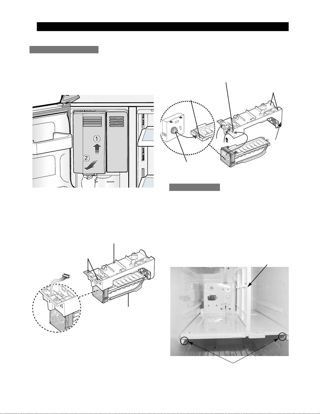
The ice dispenser is located in the upper portion of
the freezer. This assembly stores ice made by the
icemaker and dispenses ice.
1. Lift the ice bucket up and slide out the ice
dispenser assembly .
The ice maker is located inside of the ice dispenser
assembly.
1.
Remove ice maker support screws (2), and slide out.
2. Disconnect the ice maker wire connector.
3.
Unlock the locking tabs to separate the ice maker kit.
In order to assemble the icemaker kit.
1. Assemble the geared motor shaft and the front of
ice tray.
2. Lift the front locking tab and assemble the ice
maker kit.
3. Connect the ice maker wire connector.
4. Match the tab holes and tabs(2) located on the
top of the liner, and slide the ice maker in.
5. Tighten the screws (2) of the ice maker support.
This shelf is designed to support the ice maker
ice dispensed and Xtra Space
TM
.
1. Remove the Xtra Space
TM
cover to push it down
and pull front.
2. Slide the partition out.
3. Remove the screws (2) on the bottom front of the
case.
4. Slide out the case while disconnecting the wire
connect.
Auger Motor Case
PARTITION
SCREWS
WIRE CONNECTOR
SUPPORT OF ICE-MAKER
FRONT OF ICE TRAY
FRONT LOCKING TAB
TAB HOLES
GEARED MOTOR SHAFT
ICE-MAKER KIT
LOCKING TAB
Ice Dispenser & Ice Maker
12
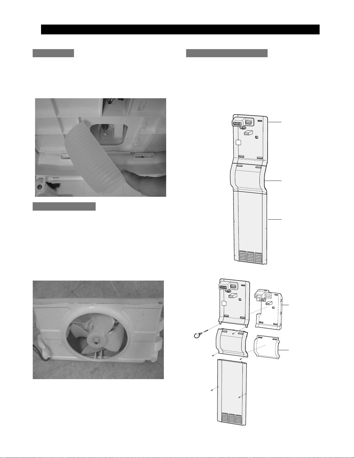
The freezer light is located in the bottom of the
auger motor case. The light is covered by an opaque
cover.
1. Remove the screw and the light cover.
The evaporator fan is located in the middle rear of
refrigerator. This fan circulates cold air in the
refrigerator.
1. Remove the fan spring, and than remove fan and
protector motor.
2. Remove screw located at the four corners of
the fan bracket.
3. Take the fan motor assembly off.
1. Remove screw (6).
2. Remove the assy cover multi fre.
3. Remove the assy cover supt motor fre.
4. Remove screw (2).
5. Remove the cover evap front.
6. Disconnect the sensor wire connector.
Evaporator Fan Motor
Freezer Light Evaporator Cover in Freezer
Mechanical Disassembly
ASSY COVER MULTI FRE
ASSY COVER SUPT
MOTOR FRE
COVER EVAP FRONT
INS SUPT
MOTOR FRE
INS MULTI FRE
13
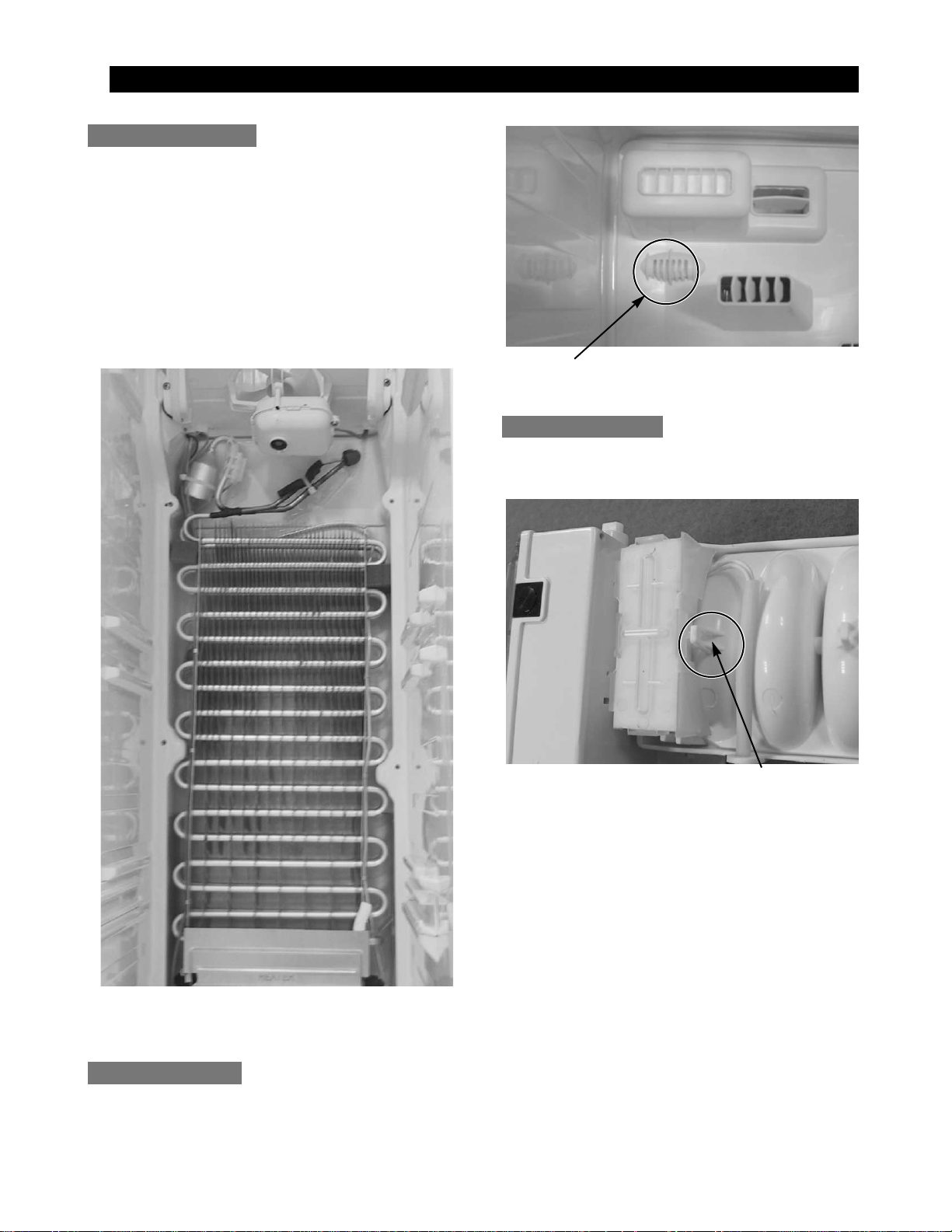
Evaporator is located in the bottom of freezer to
produce cold air driven across the evaporator coils.
1. Take off the ductwork in Freezer.
2. Disconnect the wire connector (Heater, Bimental,
and Thermistor).
3. Desolder the inlet and outlet tubes.
4. Remove the evaporator.
5. Take the same steps to seal the system as
mentioned earlier.
The freezer thermistor is located at the top left of
freezer vent. It sends temperature signals to the
micro-processor.
The Ice-Maker thermistor is located in its bottom.
The temperature signal sends the micro-processor.
Evaporator in Freezer
Mechanical Disassembly
Freezer Thermistor
Ice-MakerThermistor
THERMISTOR
THERMISTOR
14
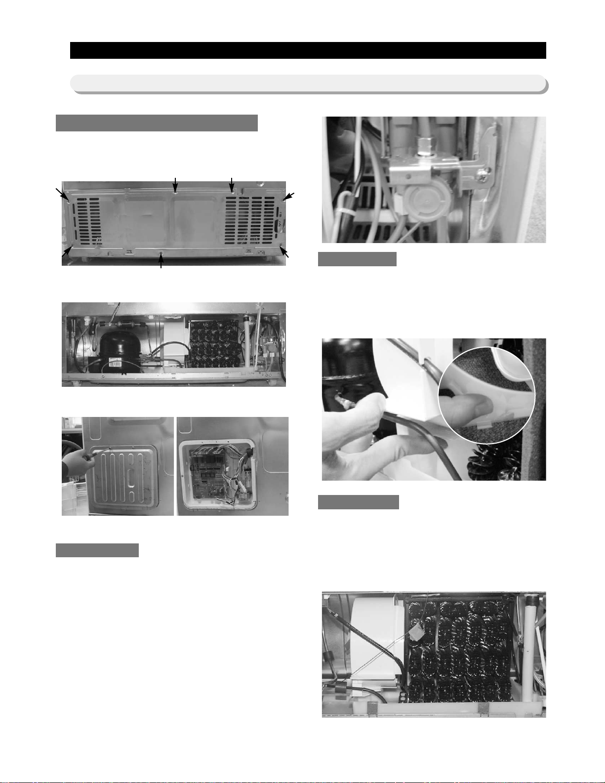
1. Disconnect the power cord of the refrigerator
.
2. Remove the fixed screws (6) of compressor
cover.
3. Slide up and take off the compressor cover to
see the machine compartment.
4. Remove screw (2) on the cover.
When the solenoids receive a signal from the microprocessor, they supply water to the water dispenser
or the ice maker.
1. Remove bracket screw on cabinet.
2. Take the solenoids assembly out.
3. Disconnect water tubes.
The condenser Fan is located in the middle of
machine compartment. It cools down the subcondenser and the compressor.
1. Lift up the rib under the support motor.
2. Pull the support motor.
The condenser is located in the machine
compartment. The heat is extracted by condenser
fan.
1. Desolder the compressor discharge the
condenser outlet.
2. Take out the condenser.
Machine Compartment Electric Box
Mechanical Disassembly
3-3) Machine Compartment Disassembly
Water Solenoids
Condenser Fan
Condenser
15
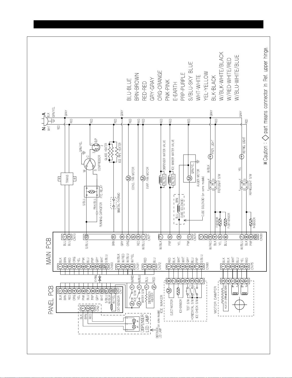
4. CIRCUIT DIAGRAM
16
5. OPERATION PRINCIPLES BY PARTS OF CIRCUIT
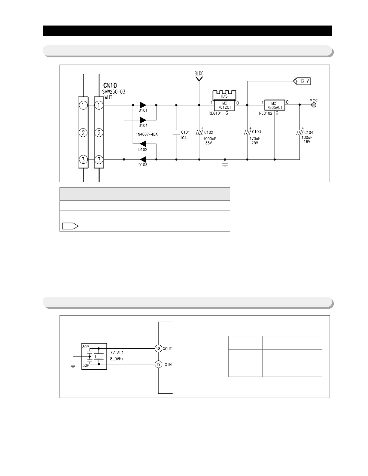
5-1) POWER
5-2) OSCILLATION CIRCUIT
Terminal Oscillation Frequency
Vcc(DC 5V)
<< BLDC
+12V(DC 12V)
MICOM POWER AND SENSORS
BLDC MOTOR POWER(NOT USE)
RELAY,PANEL POWER
● When turned on, rectified AC v oltage which is stepped down on 2nd transf ormer flows between and
at about AC 15V, goes through the diode D101 and D104 is changed to DC, and provide constant 12V.
It provides 5V to MICOM and other circuits via regulator REG102 (MC7805ACT), and make entire PCB
operate.
● It is an Oscillation Circuit f or synchronism clock gener ation and time calculation on the information sending &
receiving of the MICOM internal logic elements and when specifications for Resonator change, the timing
system of MICOM changes resulting in errors. (Rated parts must be used)
Terminal Oscillation Frequency
Xin(#19)
Xout(#18)
8.0MHz
8.0MHz
17
OPERATION PRINCIPLES BY PARTS OF CIRCUIT
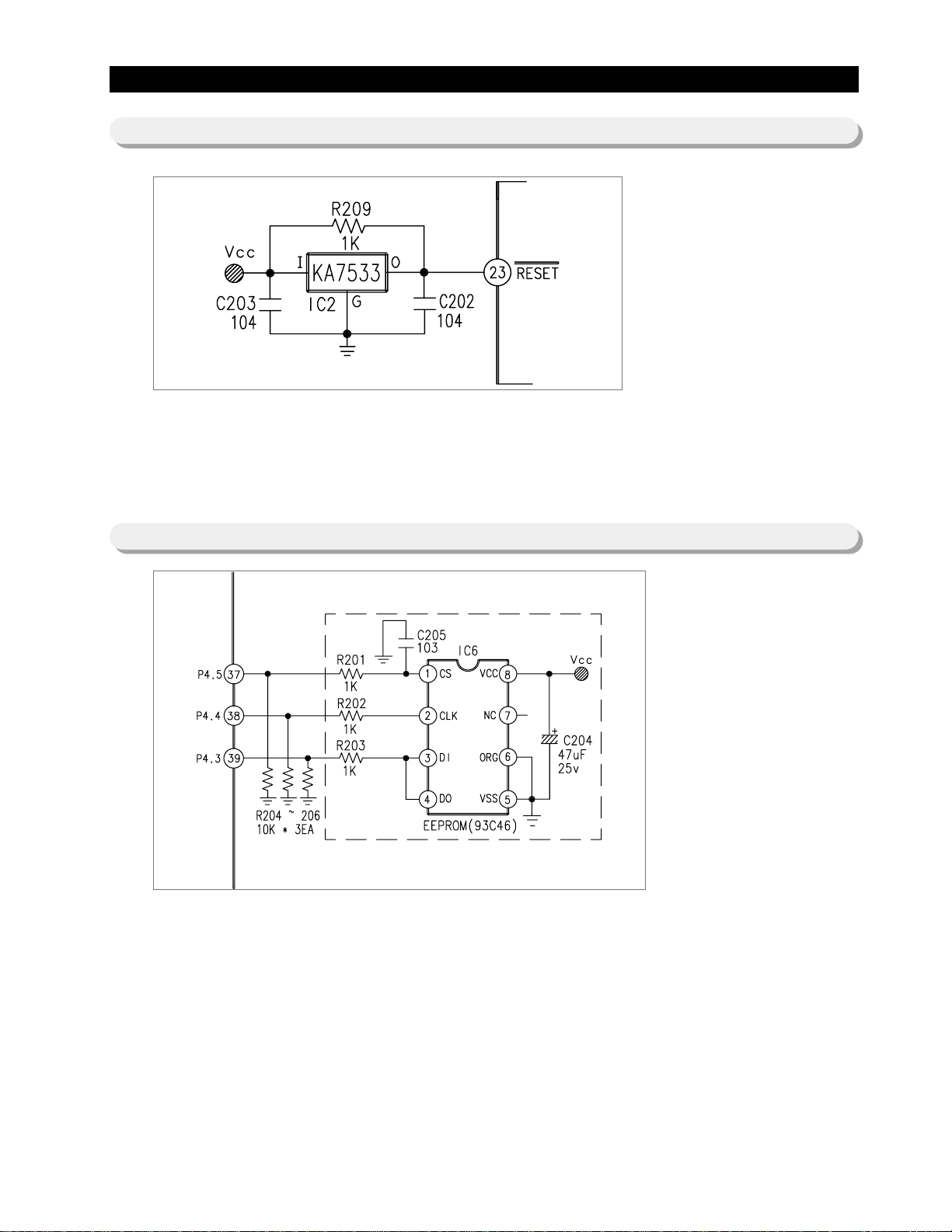
5-3) RESET CIRCUIT
5-4) EEPROM DETECTION CIRCUIT
● RESET Circuit allows the whole program to go back to the initial setting by initializing parts such as the RAM in
MICOM with the power supply into MICOM or with an instant power failure .
Upon the power supply, the reset terminal voltage becomes "LOW" f or se v eral tens of compared to Vcc
voltage(DC 5V) at MICOM, and it maintains "HIGH"(Vcc Voltage) during normal operation.
But, when Vcc drops down to 3.4~3.7V, the reset terminal voltage becomes "LOW".
● A semiconductor memory EEPROM stores data remembering previous settings regardless of power-off, which
are indispensable especially in power fluctuating areas. Also , EEPR OM sets and uses other options in principle.
18
OPERATION PRINCIPLES BY PARTS OF CIRCUIT
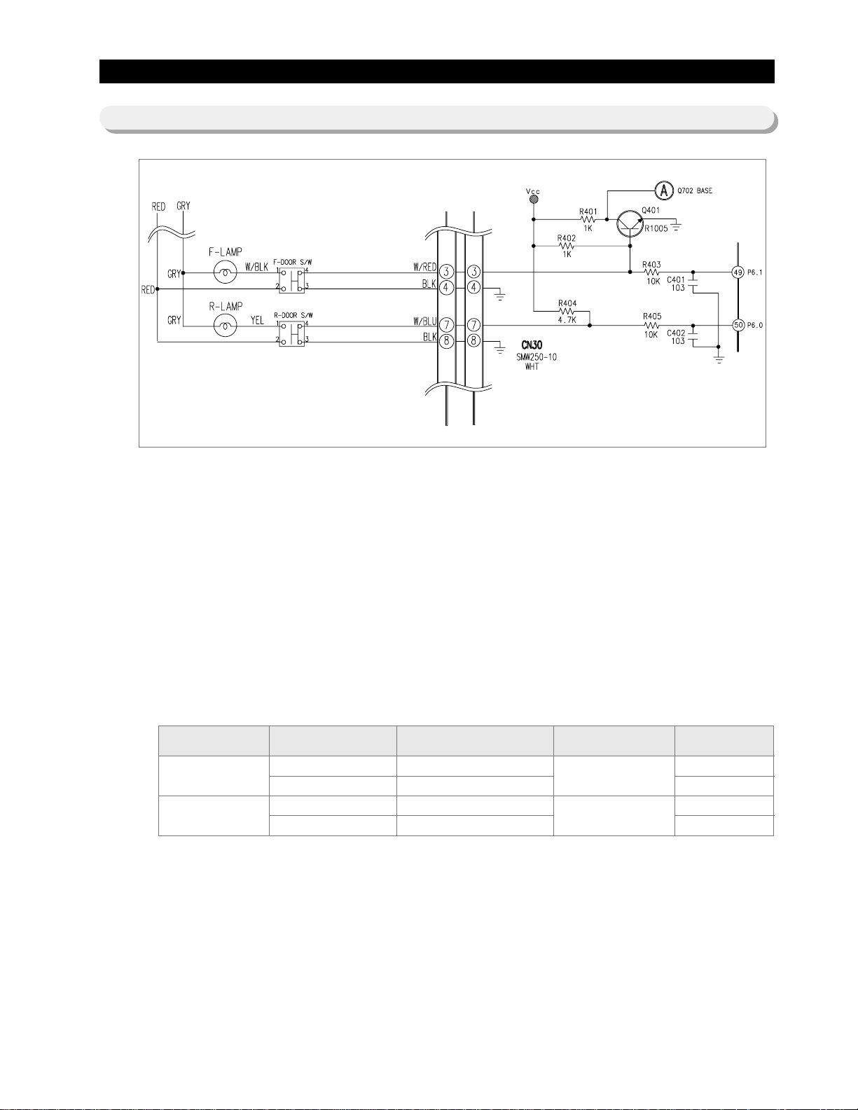
5-5) DOOR SWITCH DETECTON CIRCUIT
1) If R-Door is opened, the contact point of the door switch (4-3) becomes open, and the current of PCB line
comes through R404 and R405 and provides 5 volt which is recognized as door is opened, and turn off the fan
at different load. When the door is closed, the voltage goes out from R404 to Switch, the MICOM is applied
with OV and the door is recognized as closed.
2) If F-Door is opened, the contact point of the door switch (4-3) becomes open, and the current of PCB line
comes through R402 and R403 and provides 5 volt which is recognized as door is opened, and turn off the fan
at different load. When the door is closed, the voltage goes out from R402 to Switch, the MICOM is applied
with OV and the door is recognized as closed.
3) Q401 is the circuit to turn off the auger motor operation when the door is opened. If the door is closed, Vcc
voltage of R402 works as ground via door switch, OV is applied to the base of Q401, and Q401 becomes
operable, Vcc v oltage on "A" part Q702 base works as emitter on Q401 collector and creates OV. (Check the
operable condition for other parts at load terminals)
4) Condition for door open is the opposite of condition 3 above .
Category Door DOOR S/W Contact Point MICOM PORT NO MICOM INPUT
CLOSE
OPEN
CLOSE
OPEN
CLOSE
OPEN
CLOSE
OPEN
"LOW"
"HIGH"
"LOW"
"HIGH"
19
OPERATION PRINCIPLES BY PARTS OF CIRCUIT
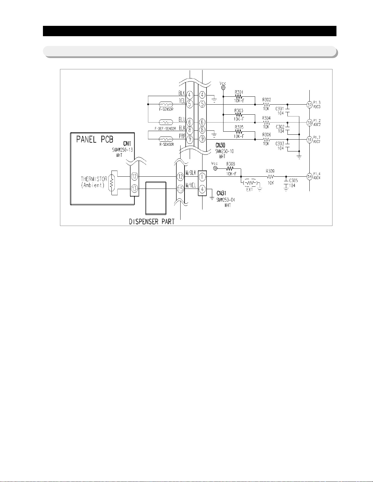
5-6) TEMP SENSING CIRCUIT
1) Sensor uses a thermistor which has a temp coefficient of negative resistance and controls resistance. When
the heat goes up, the resistance gets down and vice v ersa. R302, 4, 6, 9 and C301~C303, C305 are parts for
noise prevention b ut the y are not related to temp sensing characteristics.
2) If Vf is the incoming voltage to MICOM in case of F-Sensor, Vf equals (Rth * Vcc)/ ((R301 + Rth). Where Rth is
resistance of THERMISTOR corresponding to Temp. Please ref er to the Appendix Temp-to-Sensor
Resistance/V oltage con v ersion table(Temp-to-MICOM Terminal Voltage included) on A/S . (Ne xt page)

20
OPERATION PRINCIPLES BY PARTS OF CIRCUIT
Temp to Resistance of Sensor & MICOM PORT Voltage
Sensor CHIP : PX41C Standard
Temp.
-50 °F/-45.6 °C
-49 °F/-45.0 °C
-48 °F/-44.4 °C
-47°F/-43.9 °C
-46 °F/-43.3 °C
-45 °F/-42.8 °C
-44 °F/-42.2 °C
-43°F/-41.7 °C
-42°F/-41.1 °C
-41°F/-40.6 °C
-40°F/-40.0 °C
-39°F/-39.4 °C
-38°F/-38.9 °C
-37°F/-38.3 °C
-36°F/-37.8 °C
-35°F/-37.2 °C
-34°F/-36.7 °C
-33°F/-36.1 °C
-32°F/-35.6 °C
-31°F/-35.0 °C
-30°F/-34.4 °C
-29°F/-33.9 °C
-28°F/-33.3 °C
-27°F/-32.8 °C
-26°F/-32.2 °C
-25°F/-31.7 °C
-24°F/-31.1 °C
-23°F/-30.6 °C
-22°F/-30.0 °C
-21°F/-29.4 °C
-20°F/-28.9 °C
Resistance()
153319
144794
136798
129294
122248
115631
109413
103569
98073
92903
88037
83456
79142
75077
71246
67634
64227
61012
57977
55112
52406
49848
47431
45146
42984
40938
39002
37169
35433
33788
32230
Voltage(V)
4.694
4.677
4.659
4.641
4.622
4.602
4.581
4.56
4.537
4.514
4.49
4.465
4.439
4.412
4.385
4.356
4.326
4.296
4.264
4.232
4.199
4.165
4.129
4.093
4.056
4.018
3.98
3.94
3.899
3.858
3.816
Temp.
-19°F/-28.3°C
-18°F/-27.8 °C
-17°F/-27.2 °C
-16°F/-26.7 °C
-15°F/-26.1 °C
-14°F/-25.6 °C
-13°F/-25.0 °C
-12°F/-24.4 °C
-11°F/-23.9 °C
-10°F/-23.3 °C
-9°F/-22.8 °C
-8°F/-22.2 °C
-7°F/-21.7 °C
-6°F/-20.6 °C
-5°F/-20.0 °C
-4°F/-45.6 °C
-3°F/-19.4 °C
-2°F/-18.9 °C
-1°F/-18.3 °C
0°F/-17.8 °C
1°F/-17.2 °C
2°F/-16.7 °C
3°F/-16.1 °C
4°F/-15.6 °C
5°F/-15.0 °C
6°F/-14.4 °C
7°F/-13.9 °C
8°F/-13.3 °C
9°F/-12.8 °C
10°F/-12.2 °C
11°F/-11.7 °C
Resistance()
30752
29350
28021
26760
25562
24425
23345
22320
21345
20418
19537
18698
17901
17142
16419
15731
15076
14452
13857
13290
12749
12233
11741
11271
10823
10395
9986
9596
9223
8867
8526
Voltage(V)
3.773
3.729
3.685
3.64
3.594
3.548
3.501
3.453
3.405
3.356
3.307
3.258
3.208
3.158
3.107
3.057
3.006
2.955
2.904
2.853
2.802
2.751
2.7
2.649
2.599
2.548
2.498
2.449
2.399
2.35
2.301
Temp.
12°F/-11.1°C
13°F/-10.6°C
14°F/-10.0°C
15°F/-9.4°C
16°F/-8.9°C
17°F/-8.3°C
18°F/-7.8°C
19°F/-7.2°C
20°F/-6.7°C
21°F/-6.1°C
22°F/-5.6°C
23°F/-5.0°C
24°F/-4.4°C
25°F/-3.9°C
26°F/-3.3°C
27°F/-2.8°C
28°F/-2.2°C
29°F/-1.7°C
30°F/-1.1°C
31°F/-0.6°C
32°F/0.0°C
33°F/0.6°C
34°F/1.1°C
35°F/1.7°C
36°F/2.2°C
37°F/2.8°C
38°F/3.3°C
39°F/3.9°C
40°F/4.4°C
41°F/5.0°C
42°F/5.6°C
Resistance()
8200
7888
7590
7305
7032
6771
6521
6281
6052
5832
5621
5419
5225
5000
4861
4690
4526
4369
4218
4072
3933
3799
3670
3547
3428
3344
3204
3098
2997
2899
2805
Voltage(V)
2.253
2.205
2.158
2.111
2.064
2.019
1.974
1.929
1.885
1.842
1.799
1.757
1.716
1.675
1.636
1.596
1.558
1.52
1.483
1.447
1.412
1.377
1.343
1.309
1.277
1.253
1.213
1.183
1.153
1.124
1.095
Temp.
43°F/6.1 °C
44°F/6.7 °C
45°F/7.2 °C
46°F/7.8 °C
47°F/8.3 °C
48°F/8.9 °C
49°F/9.4 °C
50°F/10.0°C
51°F/10.6 °C
52°F/11.1 °C
53°F/11.7 °C
54°F/12.2 °C
55°F/12.8 °C
56°F/13.3 °C
57°F/13.9 °C
58°F/14.4 °C
59°F/15.0 °C
60°F/15.6 °C
61°F/16.1 °C
62°F/16.7°C
63°F/17.2 °C
64°F/17.8 °C
65°F/18.3 °C
66°F/18.9 °C
67°F/19.4 °C
68°F/20.0 °C
69°F/-45.6 °C
70°F/20.6 °C
71°F/21.7 °C
72°F/22.2 °C
73°F/22.8 °C
Resistance()
2714
2627
2543
2462
2384
2309
2237
2167
2100
2036
1973
1913
1855
1799
1745
1693
1642
1594
1547
1502
1458
1416
1375
1335
1297
1260
1225
1190
1157
1125
1093
Voltage(V)
1.068
1.04
1.014
0.988
0.963
0.938
0.914
0.891
0.868
0.846
0.824
0.803
0.783
0.762
0.743
0.724
0.706
0.688
0.67
0.653
0.636
0.62
0.604
0.589
0.574
0.56
0.546
0.532
0.519
0.506
0.493
21
OPERATION PRINCIPLES BY PARTS OF CIRCUIT
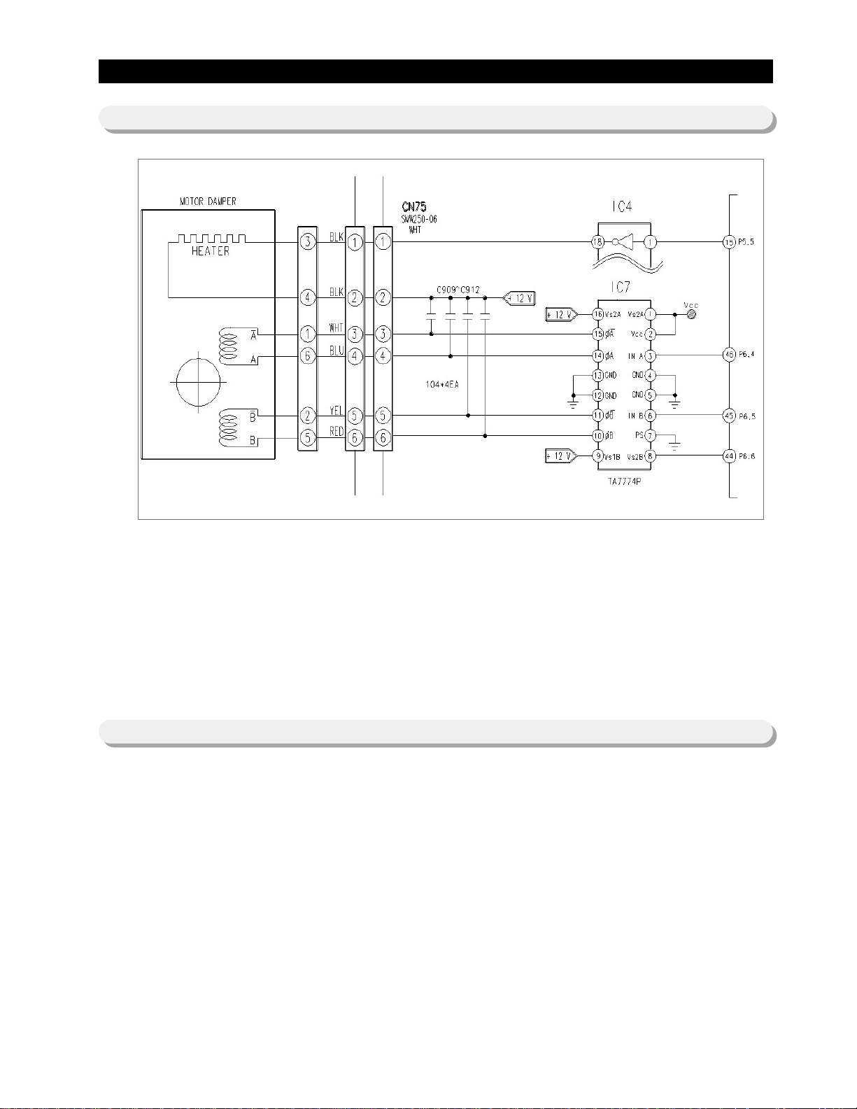
5-7) DAMPER CIRCUIT
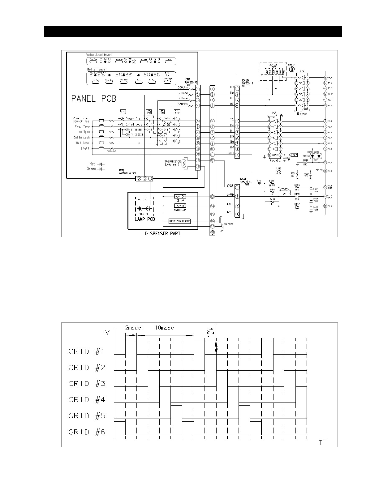
5-8) DISPLAY Circuit
1) The temperature of R-room is controlled by opening and closing of damper with stepping motor, supplying &
blocking cold air .
2) TA7774P (IC07) operates the damper. TA7774P is the driver IC only for step motor . If the regular signal is
provided to TA7774P from Micom, send combined signal to Quad-Polar step motor to rotate on certain
direction. This makes clockwise or counter clockwise rotation to make the damper open or close .
3) Since the damper always touches the cold air , DC 12V/1W heater is installed, alwa ys on to pre v ent the
malfunction from moisture and is controlled on conditions. (Operation conditions can be changed). Micon #15
pin connected to IC4 controls the damper heater like category 3.
1) KEY SCAN
When Grid #6 is output, this signal goes through PCB resistance 10 and provided to power frequency .
When the switch is pressed, R502(6.8 ) and R501 (12 ) decrease the signal and less than 5.1V peak to
peak signal is provided to MICOM, the MICOM recognizes the grid #6 is provided, and change the function
corresponding to switch ke y. [Refer the circuit diagram below]
22
OPERATION PRINCIPLES BY PARTS OF CIRCUIT
2) DISPLAY OPERA TION
Like the signal diagram below, Micom sends “ high ” signal through MICOM 6 terminals of NO #1 2 3 4
5 6 for 2ms every 12ms. This signal goes to output terminal via input terminal of IC5 (KID65783AP or
TD62783AP). Output wave alw a ys goes through LED input terminal with DC11~12V on every period. At this
time, if SINK signal comes out at IC4, DC11~ 12V is applied to LED input terminal and output terminal sinks to
OV which turn on LED for 2ms F or e xample , to turn on "Po wer Fre." LED, IC4 #16 pin sinks to 0V when IC5
#16 becomes DC 11~12V making "Pow er F re" LED turn on.
GRID WAVE PATTERN