

Page 1
52
Check the exchange of fuse and
disconnection cause.
- Check the connections of main PCB.
- Check the connections between upper
hinge and CABI-door.
- Check the connections between door and
panel PCB.
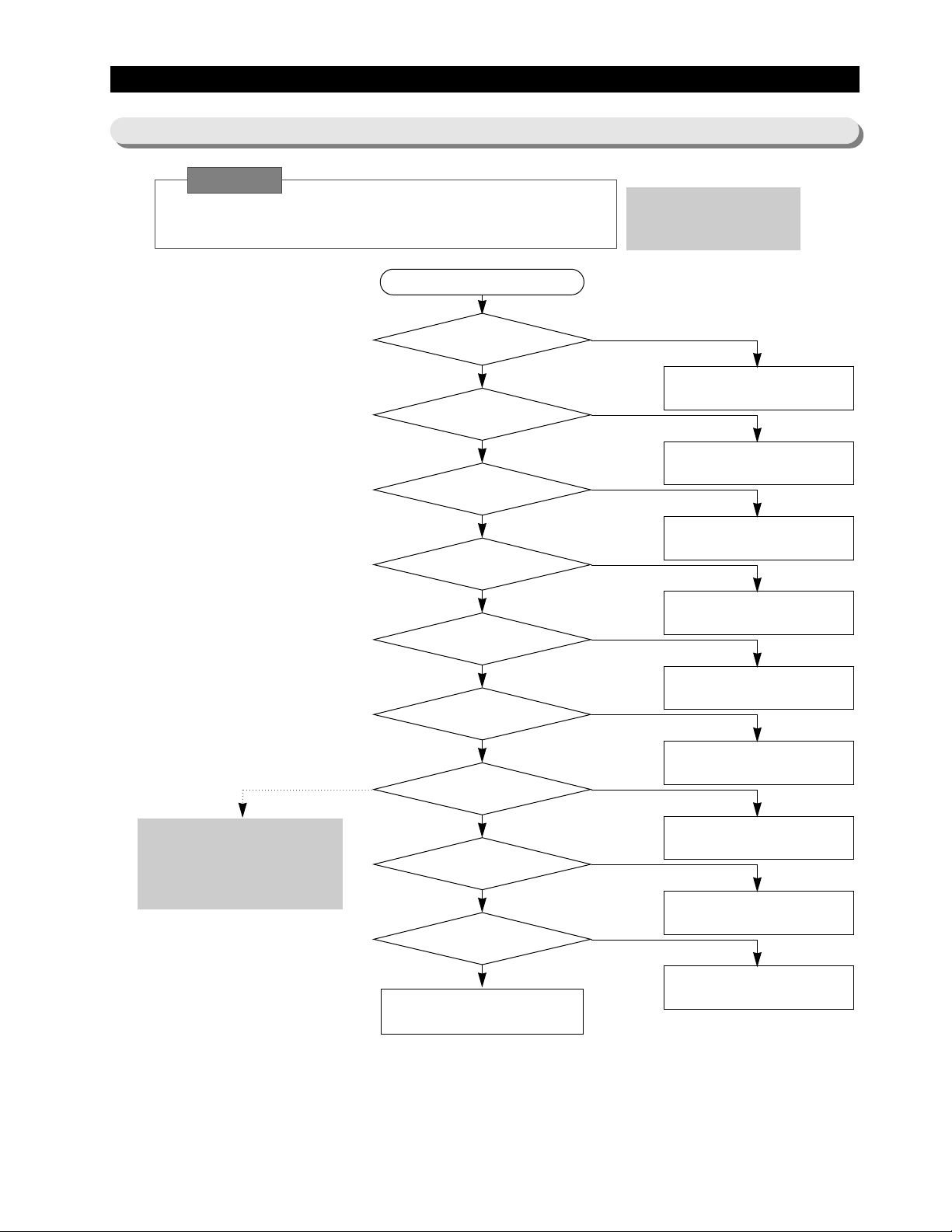
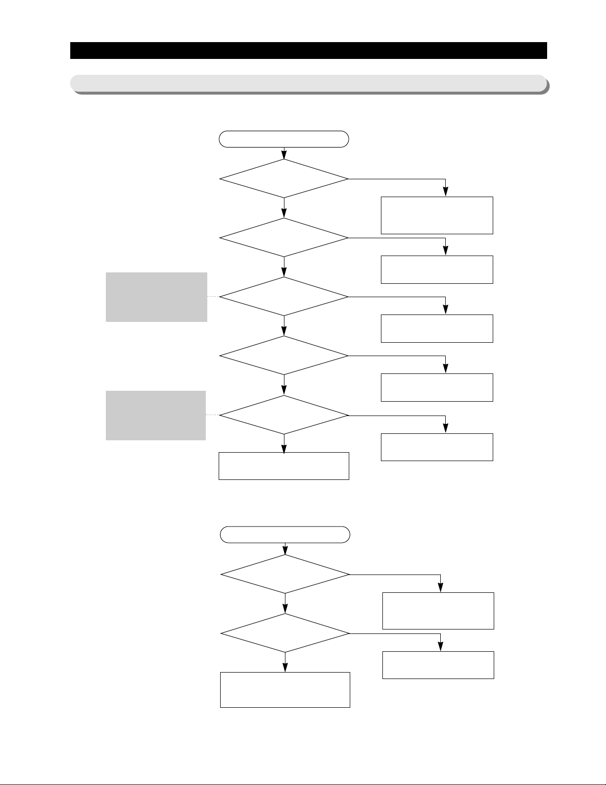
11. Diagnostics
11-1) If power is not ON
At the power of main PCB, the 1 15V power and a high-voltage over DC
170V occur. Please take care of yourself on repair and measurement.
Is 230V AC fuse down?
Is power 230V
both terminals of CN10?
Is fuse on main PCB down?
Is DC 320V impressed to both
terminals of BD1?
Top S/W 233Y
Is the voltage impressed DC 5.8V
between C and S ?
Is 12V impressed to both
terminals of C102?
Is the load such as relay normal?
Is normal the load, such as
relay?
Is there any PCB soldering, short or broken?
Normal
Start
To check the main PCB, please apply
descriptions of operation and
references in the manual.
YES
Check the assembly and connection of
electric wires.
NO
Exchange fuse
250V/ 2A?
YES
Check the PCB pattern and replace BD1.
NO
Replace PCB assembly.
NO
1) Replace D104 (D5S6M).
2) Replace PCB assembly.
NO
Replace REG1(KA7805)
NO
1) Check the assembly of electric wires and troubleshoot.
2) Replace the panel PCB.
NO
1) Replace the corresponding relay.
2) Check lead wire for contact.
NO
Caution!
Page 2
53
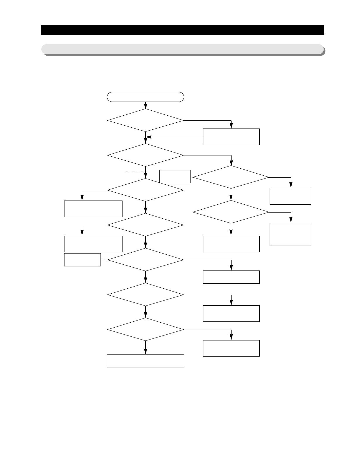
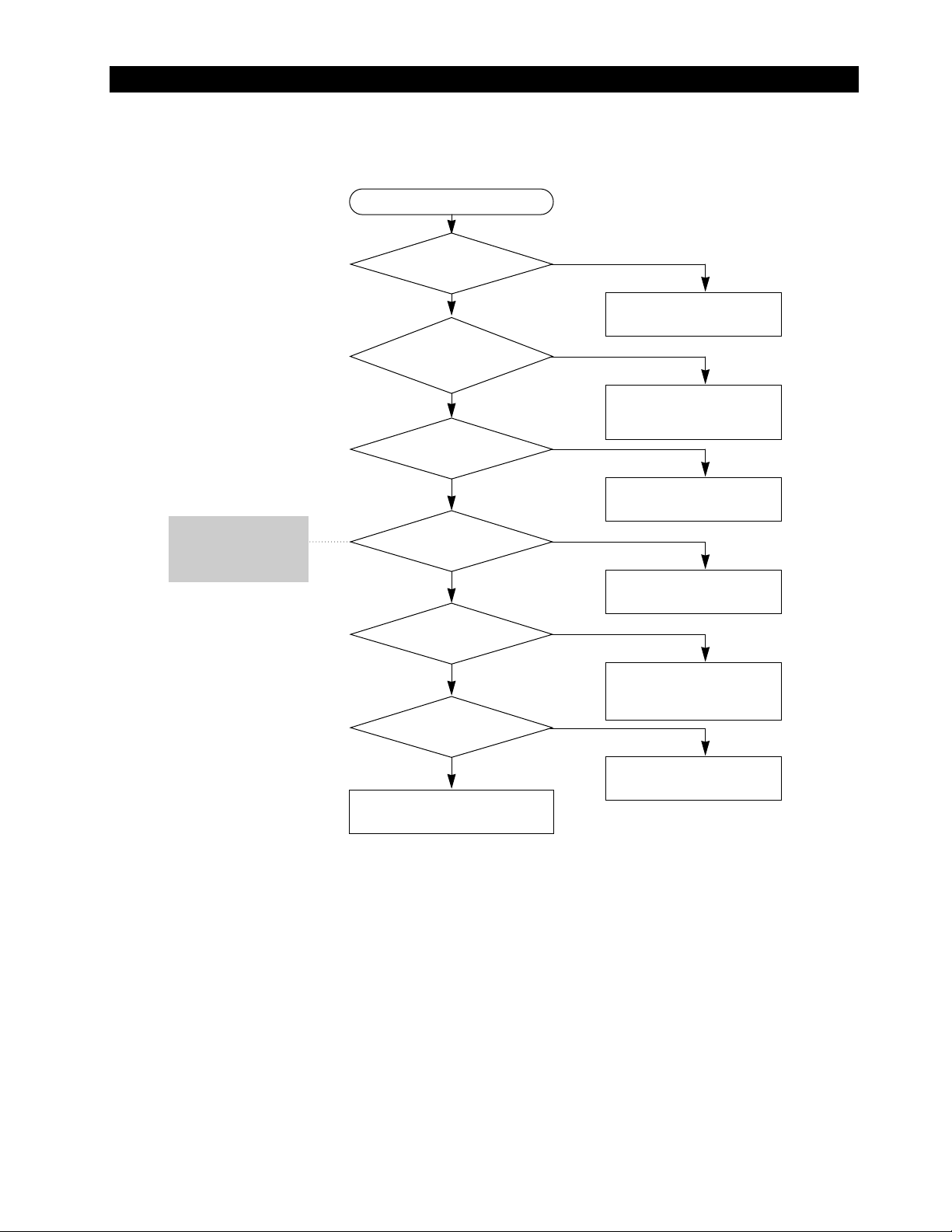
Diagnostics
1 1-2) If the compressor and cooling fan motor don’t work normally
Apply Ref.4
Did 5 min pass after COMP. OFF?
Start
Check after a lapse of 5 min.
Did buzzer sound on forced operation?
(Check certainly after forced start.)
Exchange MICOM and PCB.
Exchange and repair IC03.
(ULN2803)
Does compressor work
with forced operation?
Is MICOM No.18 High?(5V)
Open and repair the
connection.
Troubleshoot the
sensor and Exchange
PCB.
Is the voltage of IC03 pin No. 14 between 0-1V?
Open and troubleshoot the
connection.
Is COMP relay normal?
Exchange or troubleshoot
COMP relay.
Apply Ref. 2
Is the contact of connector CN70 normal?
Insert connector completely?
Is COMP assembly normal?
Exchange and repair COMP.
assembly.
Normal
NO
YES
YES
NO
NO
NO
NO
YES
NO
YES
YES
YES
NO
YES
NO
YES
NO
YES
Is freezer sensor normal?
Is the temp. sense
of main PCB Normal?
Page 3
54
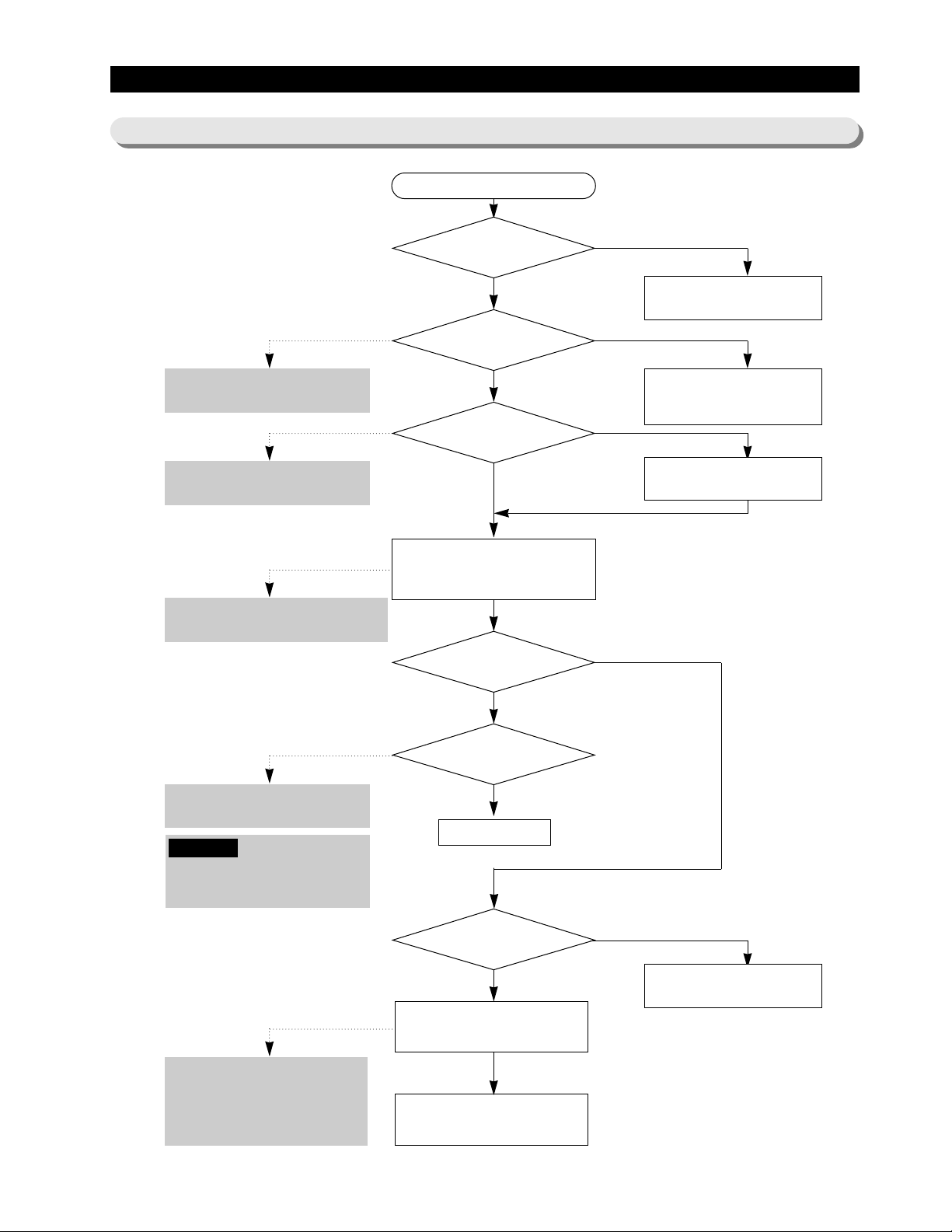
Diagnostics
11-3) If defrost function
Is F, R defrosting sensor by
self-diagnosis normal?
Start
Exchange and troubleshoot the
corresponding sensor.
See Ref. 3: ‘Check load’ in the manual.
Make decision on the basis of ref. 4 and
6 in the manual.
See test function in the manual.
Recheck the corresponding sensor for
an error if it fails in return.
See ‘Load Drive Circuit section’ and
Ref. 2: How to check failure of relay.
Is F, R Room defrosting heater normal?
Check temp. fuse,
breaking of heater wire, contact of
wire and so on.
Is temp. of the defrosting
sensor below 23℉?
Run forced operation for a
specified period.
Repair the connection terminal.
Perform forced defrosting for F and
R room at a time.
Normal
Check temp. fuse, breaking of heater wire,
contact of wire, and so on.
Exchange or troubleshoot the failure relay or
exchange PCB ass’y.
Is power applied to the
respective defrosting heaters?
Does the system
return to cooling operation after heating
for a specified period of time?
Recheck the connection
terminal in Main PCB
NO
NO
YES
YES
NO
YES
NO
NO
NO
YES
YES
YES
If temp. of F, R defrosting sensor by the
working of heater are over 10℃, 17℃
Reference
Page 4
55
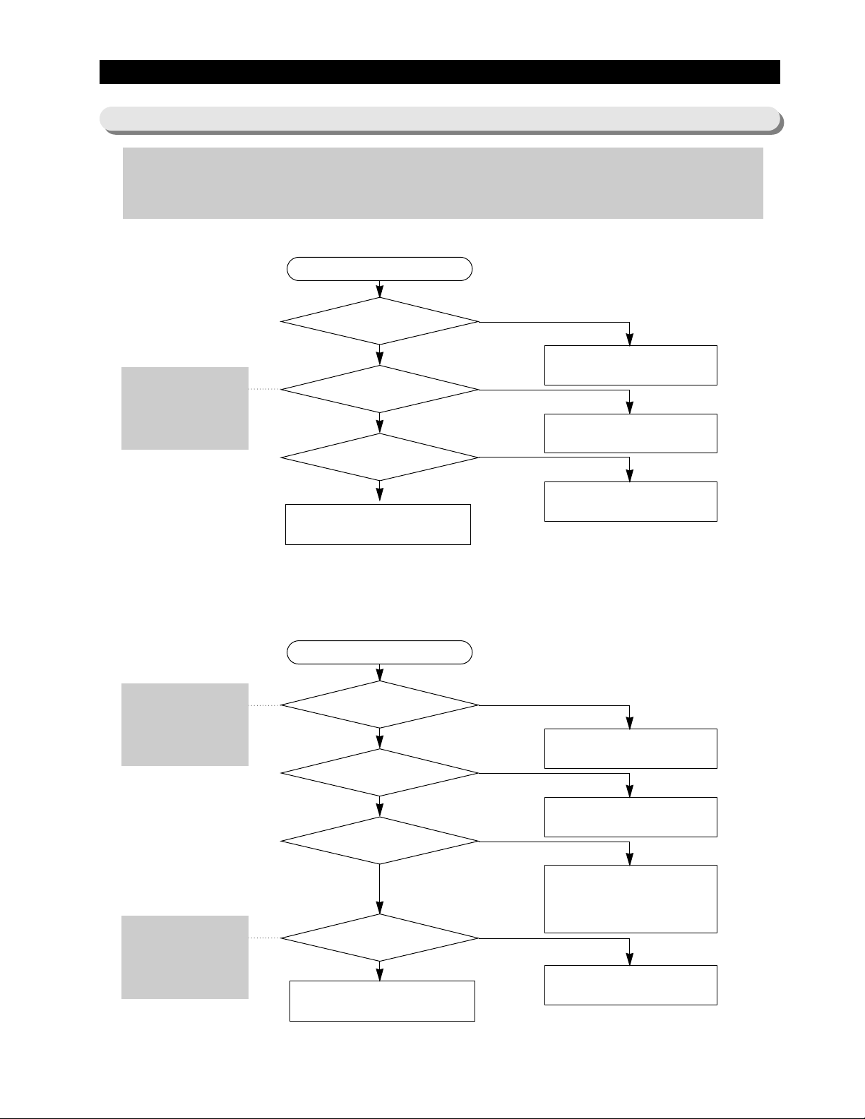
Diagnostics
1 1-4) If there is a trouble with self-diagnosis
1) If the ambient sensor has trouble
No trouble with PCB and temperature sensor.
Recheck the contact failure of connector.
YES
YES
YES
2) If the temperature sensor of F and R room has trouble
See Ref. 4 (descriptions of
circuit operation, and how
to check temperature
sensor in the manual.)
- Error of sensor can be seen on the front display of refrigerator. If power is impressed to refrigerator first, an failure of sensor is found. The refrigerator
will stop working and display(blink) the region of trouble-occurred sensor repetitively.
- Even if sensor has failure during the operation, the refrigerator will not stop working but can run the normal cooling operation because of being operated
in the Emergency Operation mode. Therefore you’ re requested to use how to check self-diagnosis in the manual.
A bad contact or connector missing?
Was the Main
– PCB connector(CN31) inserted
correctly?
Is the ambient temperature
sensor normal?
Is the input of voltage to
MICOM pin No. 63 normal?
Start
NO
Exchange the temperature sensor.
NO
Check the iced solder and
short of main-PCB.
NO
YES
YES
YES
YES
See Ref.4 (descriptions of
circuit operation, and how
to check temperature
sensor in the manual.)
For sensor resistance per
temperature, make use of
the resistance values from
Ref. 4 and 5.
Exchange the temperature sensor.
Is the unit of
Fridge’s temperature
sensor normal?
Was the Main – PCB
connector(CN30) inserted
correctly?
Is the sequence of
insertion of connector(CN30) wire identical to
the circuit diagram?
Is the input voltage to
MICOM pin No. 59 normal?
Start
NO
Troubleshoot a bad contact or missing of
connector.
NO
Check if the iced solder of main PCB is
short.
NO
Modify the wrong configuration of connector
wire -in case of being not inserted or
incorrectly inserted - to be coincided with the
circuit diagram.
NO
No trouble with PCB and temperature sensor.
Recheck the connector for an error of contact.
Page 5
56
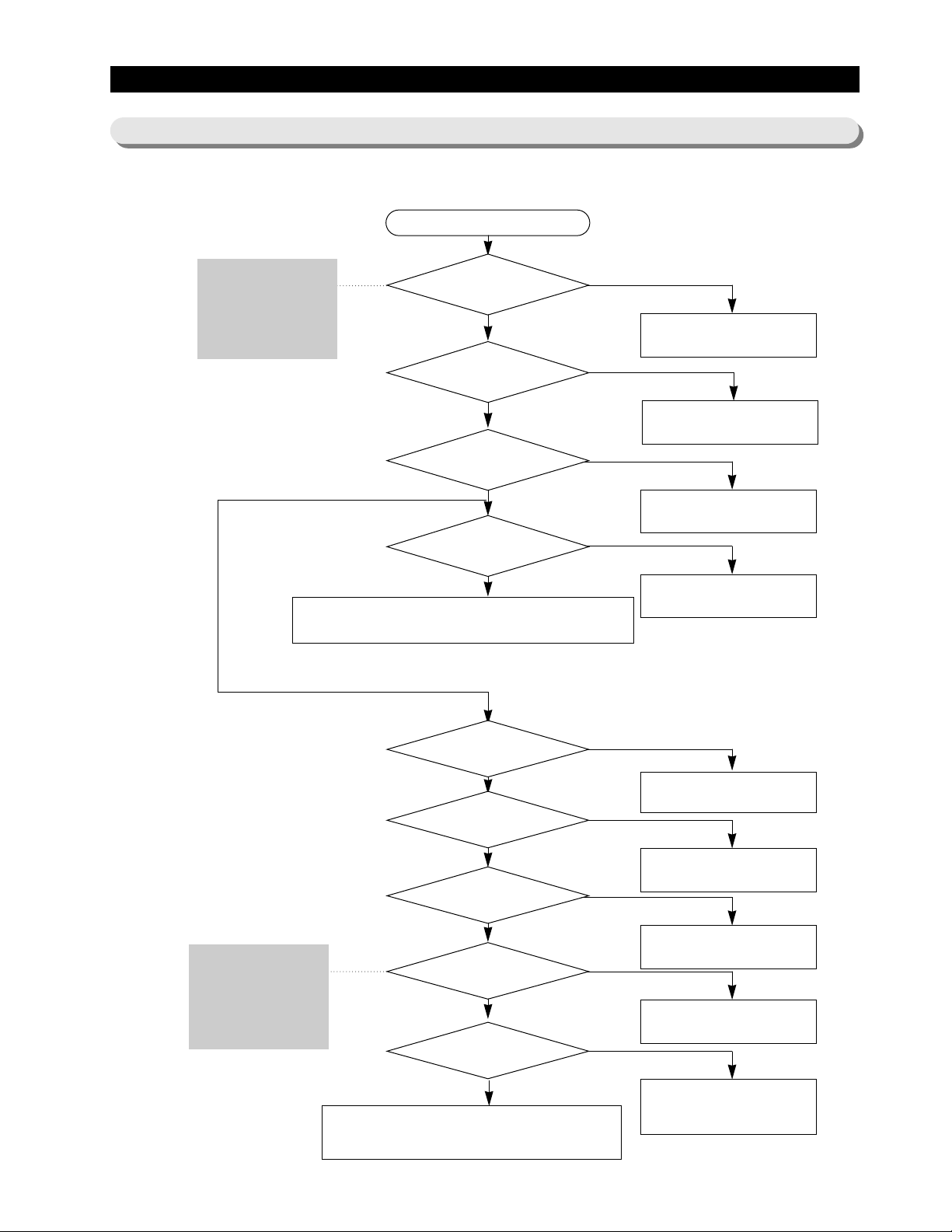
Freezer door MICOM No. 43,
Fridge door MICOM No. 44
– Regular voltage are 5V to Open :
0V to Close.
Separate the door S/W and
check if the measured value of
unit is changed from 0 to∞Ω
according to S/W ON/OFF.
1) If “Ding-Dong” sounds continuously
Isn’t the door opened minutely?
Start
Remove causes after
comprehending the conditions of
interference by door gasket, food etc.
Isn’t water penetrated
into the door S/W?
Exchange the door S/W.
Is the input voltage of
main No. 43 and 44 changed at door-open,
door-close?
Troubleshoot the breaking of wire and
bad door S/W.
Main PCB and door S/W are normal.
Yes
NO
No
YES
NO
Connector not inserted. Troubleshoot
poor contact.
NO
Exchange the door S/W.
NO
YES
Is the state of inserted connector
(CN30)being normal?
YES
Is the door S/W self-unit normal?
YES
2) If “Beep” sounds continuously
Didn’t you
select forced operation and forced
defrosting?
Start
Release the forced operation and
forced defrosting functions, or turn ON
again after power OFF.
Do buzzer
still sound after power-on
again?
Main-PCB is normal
Check if there is any short parts due to
foreign matters and the test
jumper part in the main-PCB.
Selected
NO
YES
YES
Diagnostics
11-5) If alarm sound
Page 6
57
Diagnostics
3) Without sound of buzzer operation
Does it sound
‘Ding-Dong’if you press a button
on front panel?
Start
Main PCB is normal; buzzer normal.
Check the panel PCB with the
reference of ‘how to check panel
display’.
Buzzer is broken – replace it.
Does it make a sound of ‘door-open’ alarm
when you are opening the door of freezer or fridge
more than 2 min?
Is the bent or go-out of the buzzer
in the main PCB?
The main PCB and buzzer are normal
YES
YES
NO
NO
YES
NO
NO
Replace the main PCB.
(failure of MICOM)
Are signals coming
out of MICOM No. 21 in a 1-sec cycle
after the Forced operation?
Is signal of Q801
Base ouputted with 1 sec. intervals
in the condition above?
Did lead of a
component fall on the vibration plate
of buzzer?
NO
Check the state of pattern connection
between MICOM No.21 and Q801.
(Check Open/Short)
NO
Poor buzzer is broken down or
replace the buzzer.
YES
YES
YES
Refer the description of
Test function in the manual
for the Forced operation.
Page 7
58
Diagnostics
11-6) If the panel PCB is not working normally:
1) Where lighting of the panel PCB is disabled, or only some lamps are disabled.
2) Where the Panel PCB key isn’t selected:
- The basic check way : If you is troubleshooting in the basic check method, then
Is the connector
of upper hinge cover inserted
normally?
Start
Reinsert the connector. Troubleshoot
a poor contact.
Is the main PCB
connector(CN50) inserted
normally?
Reinsert the connector in the main
PCB.
Is the connector of
door panel PCB connector inserted
normally?
Reinsert the connector. Troubleshoot
a poor contact.
1. Check the door wire of freezer – the disconnection of wire, short between wires.
2. Check the CABI wire of freezer – the disconnection of wire, short between wires.
3. Check the panel lighting circuit section within the main PCB for short open.
1. Check the door wire of freezer – check the breaking of wire, short between wires.
2. Check the CABI wire of freezer – check the breaking of wire, short between wires.
3. Check for Short/Open of the Panel Lighting Circuit section in the main PCB.
NO
NO
YES
YES
NO
Panel PCB itself has trouble.
YES
YES
Is lighting operated
normally when the exchange of panel
PCB?
NO
NO
Recheck after the release of locking
function.
YES
Is the locking lamp lit on?
YES
Reassemble the PCB ass’y/Enforce
the cancellation of pressed keys.
NO
Aren’t a key or more buttons
pressed continuously?
YES
Reassemble the PCB ass’y/Enforce
the cancellation of pressed keys.
Operated by
separation
Isn’t the PCB system
still operated by seperating of the
mechanism?
NO
Panel PCB has trouble for itself.
YES
Is lighting
operated normally in the exchange
of panel-PCB?
YES
1. Replace the main PCB.
2. Check the short wires of CoolSelect
Zone
TM
panel.
NO
Is a periodic
wave form outputted from the main
PCB IC9?
See Ref. 1: ‘View of the
connection cabinet-door
for the wire assembly’ in
the manual.
Refer to the description of
circuit operation in the
manual 10-6) Key scan
and display Circuit
selection’s, and measure
the wave pattern.(page 40)
Page 8

59
Diagnostics
1 1-7) If fan doesn’t work:
The refrigerator has been applied with the BLDC fan motor. For RS2533, R room Fan is AC motor used. The BLDC
motor is driven by DC 8-12V.
Under the normal condition of COMP ON, it is operated together with F-FAN motor. With operation of the CoolSelect
ZoneTMfunction, the F-Fan motor may do not work. If the door is opened and closed once at a high ambient
temperature, the BLDC motor would be operated after a 1-minute or longer delay. Therefore, you’ re advised not to
take it for an error .
When the refrigerator is open, the freezer fan motor will also stop working simultaneously with the fan motor. (for the
purpose of performance improvement).
Reference
COMP OFF?
Start
Execute Forced
operation. (See page
34 in the manual)
Is the voltage DC 9-11V between
GND of the main-PCB section and
CN72 pin No. 6?
Fan works normally.
Is the voltage DC 0V between
CN30 No. 1 and No. 2
in the main-PCB?
Troubleshoot the
connections of door S/W.
In the first power application, the
freezer / fridge / compressor fans
work for 5 minutes regardless of the
condition.
Apply power around 5 minutes
after the power OFF. (Prevent
overload of compressor.)
Expected causes :
1. Check if the fan motor has failure itself.
2. Check if the wire connections have a trouble of contact.
3. Check the input of the fan motor rotation pulse in the operation motor
fan. (See the details of Fan Motor Drive Circuit section.)
YES
YES
NO
NO
NO
YES
Is the voltage DC10V between
GND of the main-PCB and pin No. 4
of CN72 ?
Is the voltage DC 0V between
CN30 No. 5 and No. 6 in the main-PCB
section?
NO
Is the voltage between GND
of the main-PCB and pin No. 4 of CN72
around DC 8-10V?
NO
YES
Does DC 9-11V alternate
with below DC 2V between GND of the main-PCB section
and CN72 pin No. 6?
Exchange or troubleshoot the
main PCB.
Measure with the door closed.
- door open: DC 5V
- door close : 0V
NO
YES
CN72 No. 3(F), 2(R),1(C) will be generated pulse signals when the motor rotates. These signals will be
inputted into MICOM. Unless signals are not inputted in the restart of motor, it will be ON 10 seconds after
the fan OFF. But if signals are not still entered, the above operation will restart four times more. Without
signals entered continuously, the motor will get restarted after 10 minutes. This function is effective where
the normal operation of motor would be restrained due to foreign matters such as ice.
Reference
Does DC 10V alternate
with below DC 2V between GND of the main-PCB section and
CN72 pin No. 5?
YES
Does DC 8-10V alternate
with below DC 2V between GND of the main-PCB
section and CN72 pin No. 4?
YES
For C-FAN
For C-FAN For R-RAN For F-FAN
For R-FAN For F-Fan
Page 9

60
Diagnostics
11-8) If CoolSelect Zone
TM
isn’t operated normally
1) If the lamp of CoolSelect Zone
TM
is not lit.
2) If the Panel PCB key isn’t selected:
- The basic method is applied to check – if you fail in troubleshooting after above the execution, then
Is the connector of
CoolSelect Zone
TM
inserted correctly
in the refrigerator?
Start
Reinsert the connector; troubleshoot
a bad contact.
Is the connector of main
PCB (CN51) inserted correctly?
Reinsert the connector in the main
PCB.
Is the connector of
CoolSelect ZoneTMpanel PCB
inserted ?
Reinsert the connector; troubleshoot
a bad contact.
1.Check the wires of CoolSelect Zone
TM
– check the disconnection of wire, short between wires.
2. Check the Lighting Circuit of CoolSelect Zone
TM
panel in the main PCB for Short/Open.
3. Check the main PCB of CoolSelect Zone
TM
assembly for Short; the wire assembly state between
the panel and main PCB.
1. Check the wires of CoolSelect Zone
TM
– check the disconnection of wire, short between wires.
2. Check Short/Open the Lighting Circuit section of CoolSelect Zone
TM
panel in the main PCB.
3. Check the short of main PCB in CoolSelect Zone
TM
. Check the wire assembly
NO
NO
YES
YES
NO
Panel PCB has trouble for itself.
YES
YES
Is lighting operated
normally in the exchange of CoolSelect Zone
TM
panel PCB?
If the Panel key isn’ t selected:
NO
YES
Reassemble the PCB ass’y/Enforce
the cancellation of pressed keys
NO
Aren’t a key or more pressed
continuously?
YES
Reassemble the PCB asswmbly and
Enforce the cancellation of pressed keys
NO
Isn’t the PCB system
still operated by separation?
NO
Panel PCB has trouble for itself.
YES
Is lighting operated
normally after the exchange of
panel-PCB?
YES
1. Replace the main PCB.
2. Check the wire shorts of CoolSelect
ZoneTMpanel.
NO
Is a periodical wave
form outputted from the main
PCB IC9?
Refer to 8-7) CoolSelect Zone
TM
,
Panel Circuit and measure the
wave form.
Page 10

61
Diagnostics
1 1-9) If the lamps of freezer / refrigerator does not light.
1. When you are exchanging the lamp of freezer, please exchange or troubleshoot it with the power OFF to
avoid an electric shock.
2. Please keep in mind you do not get burnt by the excessive heating of an incandescent light bulb.
Is the inside lamp filament cut?
Start
Exchange or troubleshoot the
inside lamp.
Does the F-door S/W
have a normal contact?
Exchange or troubleshoot the
door S/W
Check the connections of F and R-door S/W;
check and troubleshoot the inside lamp socket.
YES
NO
NO
YES
Caution!
Separate the door S/W and measure its
resistance with a measure. As the result,
every Open/Close of the door S/W should turn 0/
∞, respectively.
1) Where 0 alone comes out : Door S/W has Short
trouble.
2) Where ∞ alone comes out : Door S/W has
Open trouble.
How to check :
If the door is opened, then the contact of door S/W is opened and MICOM gets applied 5V to finally sense Open. If 5V has been sensed over two
minutes afterwards, then an Door-Open alarm will sound ‘Ding-Dong’ for 10 seconds in a one-minute cycle. For that reason, if the door S/W has failure, the
refrigerator can make a “Ding-Dong” sound per a one-minute cycle. Please note step for its service!
Reference
Page 11

62
Diagnostics
11-10) If the solenoid in the ice-chute cover doesn’t work :
Is the S/N(solenoid) for
0.3 sec operated after 5 seconds
from power ON?
Start
Is MICOM No. 27 on
PCB maintaining High for 0.3 sec at the first
power ON?
Press Ice lever and keep it open.
Is the cover closed of
S/N after about
7∼10 seconds?
With the ice S/W ON
and ICE S/W on, ice-movement motor in F room?
Does C-E(between C and E)
of TR Q701 turn ON for 0.3 sec?
MICOM control port is normal.
Exchange the main PCB assembly.
The S/N control PCB assembly and
wire system have no trouble.
All the control system of cover iceroute has no trouble.
Check the ICE S/W, and troubleshoot
the wire connection syste
m.
- Main PCB and the sensing section of
ice-S/W are normal.
- Check the operation of SSR71 and
Q701.
Check the stop lever and support
time-delay.
After replace TR Q701 and check SSR71 then
exchange the failed components or replace the
PCB assembly.
TR701 and SSR71 are normal
YES
YES
NO
YES
YES
YES
YES
YES
NO
NO
NO
NO
NO
1) Check if the solenoid is unconditionally operated for 0.3 sec, independent of the Open/Close condition of cover ice-route, after
a lapse of about 5 seconds from power ON. (Before installation, the cancellation of cover ice-route open is enabled.)
2) Check if the connector in upper hinge section is hook-up correctly.
Preliminary check
Subject to the ice
S/W ON, do CN31 No. 2 and MICOM No. 45
get impressed 0V?
Page 12

63
Is ice ejected?
What’s your selection
between crushed and cubed?
Is the cube ice ejected sufficiently?
Does ice in the ice tray exist ?
Do you see Ice Stop on the digital panel?
Is the Crushed Ice extracted
sufficiently?
Start
The close condition on operation
is subject to the freezer door.
1) Check the ice-ejector S/W.
2) Check the door S/W.
3) Check the ice moving motor.
4) Check the cut of wire in the Ice
moving Motor section.
Cancel Ice Stop, select
the Cubed/Crushed ice.
Normal operation
1) Check the water hose for folding or
fastening.
2) Check the ice-water-way and
solenoid value
3) Check the wires of ice-maker.
NO
Crushed ice
Cubed ice extracted
Normal operation
YES
NO
Does MICOM No. 25 turn 5V if
pressing Ice S/W?
Failure of Main PCB and exchange it.
YES
NO
Does the voltage
of IC3 No. 18 turn 0V even in the ice
S/W OFF?
Failure of Main PCB(IC3) and
exchange it.
YES
NO
Does the contact
shelf of RY77 relay turn 0Ω even in the
power OFF?
Failure of Main PCB – exchange.
(The contact terminal of RY77
relay short failure.)
YES
NO
Failure of Main PCB. –Exchange it.
NO
Failure of Main PCB(IC3) –
exchange it.
Main PCB is normal.
- - - Necessary to check other sections.
1) Check the wire between terminals of the AUGER motor
and main PCB.
2) Failure of cube solenoid itself, or bad contact of the
connector.
Main PCB is normal.
- - - Check other sections.
1) Check the wire between the
AUGER motor and main
PCB.
Measure both contact
terminals of RY77 after the
separation of CN70, CN71
connectors.
Measure both terminals of RY77
contact after the separation of CN70,
CN71 connectors.
NO
Exchange of Main PCB(RY77
relay).
NO
Cubed ice
NO
Does MICOM No. 25 turn
5V if pressing Ice S/W?
Does IC3 No. 18 turn 0V if
pressing Ice S/W?
Does the
contact shelf of RY77 relay turn 0Ωif
pressing ICE S/W?
YES
YES
YES
NO
NO
YES
YES
YES
Diagnostics
1 1-11) If Crushed Ice/Cubed Ice doesn’t work properly:
Page 13

64
Check with power applied.
The Door S/W is a two-contact switch. One
detects Door Open/Close with DC 5V at the
PCB and the other one turns on/off the room
light.
(R-Room Light)
1 . Check if the light comes on by opening the R-Door. If it lights up, check if the light goes off by pressing down
the Door S/W with the door open.
If there is any problem, check the R-Door S/W.
(R-Door Open Sensing Part of MAIN PCB)
1 . Place the positive(+) terminal on CN30 No.⑤ and the negative(-) on No.⑩.And,check the voltage.
2. When the voltage is DC 5V with the door open, it is normal.
3. When the voltage is DC 0V with the door closed, it is normal. If there is any problem, check the Door S/W and
the wire connections.
(F-Room Light)
1 . Check if the light comes on by opening the F-Door. If it lights up, check if the light goes off by pressing down
the Door S/W with the door open.
If there is any problem, check the F-Door S/W.
(F-Door Open Sensing Part of MAIN PCB)
1 . Place the positive(+) terminal on CN30 No.① and the negative(-) on No.⑨. And,checkthe voltage.
2. When the voltage is DC 5V with the door open, it is normal.
3. When the voltage is DC 0V with the door closed, it is normal. If there is any problem, check the Door S/W and
the wire connections.
Disconnect the connector from the Main PCB,
than measure the resistance of the following
sensors.
1. Check the resistance the Freezer sensor cn30 between the no. 2 and 3.
2. Check the resistance the Fridge Room sensor cn30 between the no. 6 and 7.
3. Check the resistance the F Defrosting sensor cn30 between the no. 2 and 4.
4. Check the resistance the R Defrosting sensor cn30 between the no. 6 and 8.
5. Check the resistance between the no. ① and ④ the ambient Air sensor cn31.
6. Check the resistance between the no. ③ and ④of the Ice-Maker sensor cn90.
7. Check the resistance between the no. ⑬ and ⑭ of the CoolSelect Zone
TM
sensor cn51.
8. Decide the sensor by comparing above resistances to the temperature of
each sensor with the conversion table of sensor resistance and voltage from
the reference temperature of Ref. 6 on this manual.
※When the resistance is ∞Ωor 0Ω,check the connection of electric wire and
sensorconnector.
Appendix ⅠⅠ(Reference for circuit diagnostics)
Ref. 1) Check sensors
Ref. 2) Check Door S/W
Main PCB
F-DOOR S/W
(If Door Close : 1<->2 OPEN)
4
R-DOOR S/W
(If Door Close : 1<->2 OPEN)
4
213
HOME BAR S/W
213
F-SENSOR
F-DEF-SENSOR
R-SENSOR
R-DEF-SENSOR
Ass'y
1
2
3
4
5
6
7
8
9
10
11
Measuring Terminals
(1<->9)
Measuring Terminals
(5<->10)
Page 14

Appendix ⅠⅠ(Reference for circuit diagnostics)
Ref. 3) Table of temperature sensor according to resistance and voltage conversion.
Temp.(℉)
-43.6
-41.8
-40.0
-38.2
-36.4
-34.6
-32.8
-31
-29.2
-27.4
-25.6
-23.8
-22.0
-20.2
-18.4
16.6
-14.8
-13.0
-11.2
-9.4
-7.6
-5.8
-4.0
-2.2
-0.4
1.4
3.2
5.0
6.8
8.6
10.4
Resistance(㏀)
98.870
93.700
88.850
84.150
79.800
75.670
71.800
68.150
64.710
61.480
58.430
55.550
52.840
50.230
47.770
45.450
43.260
41.190
39.240
37.390
35.650
33.990
32.430
30.920
29.500
28.140
26.870
25.650
24.510
23.420
22.390
Voltage(V)
4.541
4.518
4.494
4.469
4.443
4.416
4.389
4.360
4.331
4.301
4.269
4.237
4.204
4.170
4.134
4.098
4.061
4.023
3.985
3.945
3.905
3.863
3.822
3.778
3.734
3.689
3.644
3.597
3.551
3.504
3.456
The input voltage to the MICOM PORT could be different by a hardware. This is a table based on the
voltage using the 10kohm-F.
MICOM PORT voltage when the sensor is open: about DC 5V(Vcc LEVEL)
MICOM PORT voltage when the sensor is shorted: about DC 0V(Ground LEVEL)
Temp.(℉)
12.2
14.0
15.8
17.6
19.4
21.2
23.0
24.8
26.6
28.4
30.2
32.0
33.8
35.6
37.4
39.2
41.0
42.8
44.6
46.4
48.2
50.0
51.8
53.6
55.4
57.2
59.0
60.8
62.6
64.4
66.2
Resistance(㏀)
21.410
20.480
19.580
18.730
17.920
17.160
16.430
15.740
15.080
14.450
13.860
13.290
12.740
12.220
11.720
11.250
10.800
10.370
9.959
9.569
9.195
8.839
8.494
8.166
7.852
7.552
7.266
6.992
6.731
6.481
6.242
Voltage(V)
3.408
3.360
3.310
3.260
3.209
3.159
3.108
3.057
3.006
2.955
2.904
2.853
2.801
2.750
2.698
2.647
2.596
2.545
2.495
2.445
2.395
2.346
2.296
2.248
2.199
2.151
2.104
2.057
2.012
1.966
1.922
Temp.(℉)
68.0
69.8
71.6
73.4
75.2
77.0
78.8
80.6
82.4
84.2
86.0
87.8
89.6
91.4
93.2
95.0
96.8
98.6
100.4
102.2
104.0
105.8
107.6
109.4
111.2
113.0
114.8
116.6
118.4
120.2
Resistance(㏀)
6.013
5.792
5.581
5.379
5.185
5.000
4.821
4.650
4.487
4.329
4.179
4.033
3.894
3.760
3.631
3.508
3.390
3.276
3.167
3.062
2.962
2.864
2.770
2.680
2.593
2.510
2.429
2.352
2.278
2.206
Voltage(V)
1.878
1.834
1.791
1.749
1.707
1.667
1.626
1.587
1.549
1.511
1.474
1.437
1.401
1.366
1.332
1.298
1.266
1.234
1.203
1.172
1.143
1.113
1.085
1.057
1.030
1.003
0.977
0.952
0.928
0.904
Page 15

66
1
2
3
5
6
7
10
11
12
14
15
17
NO CODE-NO PART NAME SPECIFCATION
Q’TY
※ The last no. of the code number such as DA41-xxxxx? for the Main PCB-ASS’Y could be changed by
MICOM and option.
Appendix ⅠⅠ(Reference for circuit diagnostics)
Ref. 4) Service part lists of each circuit board.
4
8
9
13
16
1
1
1
1
1
1
1
1
1
1
1
1
1
1
1
0
DA41-00195A
DA41-00195B
DA41-00185A
DA41-00103T
DA41-00103U
DA41-00173A
DA32-00006B
DA32-00006A
DA32-10109V
DA32-10109W
DA32-10109X
DA27-00002A
DA41-00185B
DA41-00173B
DA41-00108A
DA32-00105U
3301-000016
MAIN PCB ASS’Y
MAIN PCB ASS’Y
MAIN PCB ASS’Y
MAIN PCB ASS’Y
MAIN PCB ASS’Y
MAIN PCB ASS’Y
R-DEFROST Sensor
F-DEFROST Sensor
Ambient Temp.Sensor
F-Temp.Sensor
CoolSelectZone
TM
PCB ASS’Y
NOISE FILTER
MAIN PCB ASS’Y
PANEL PCB ASS’Y
CoolSelectZone
TM
PCB ASS’Y
R-Temp.Sensor
F-Temp.Sensor
FERRIETE CORE
(LOCK TYPE)
①Basic ②Basic with H/B
①Basic with CoolSelectZone
TM
①Dispenser ②Dispenser with H/B
①Basic ②Basic with H/B
①Basic with CoolSelectZone
TM
①Dispenser ②Dispenser with H/B
PX-41C
PX-41C
PX-41C
PX-41C (Use Only Dispenser Models)
PX-41C
USE ALL MODEL
①
Dispenser with CoolSelectZone
TM
②
Dispenser with H/B & CoolSelectZone
TM
①
Dispenser with CoolSelectZone
TM
②
Dispenser with H/B & CoolSelectZone
TM
①
Basic with CoolSelectZone
TM
②Dispenser with CoolSelectZone
TM
③Dispenser with H/B & CoolSelectZone
TM
PX-41C
PX-41C (Use Only Basic Models)
-
Page 16

67
Page 17

68
CIRCUIT DIAGRAM
For Basic Models
BLK
BRN
RED
ORG
YEL
PNK
BLU
PRP
GRY
WHT
S/BLU
W/BLK
W/RED
W/BLU
WHT
WHT
BLK
BRN
RED
ORG
YEL
PNK
BLU
PRP
GRY
WHT
S/BLU
W/BLK
W/RED
W/BLU
12
13
14
13
12
13
14
RED
RED
RED
RED
W/BLK
GRN/YEL
GRN/YELGRN/YEL
RED
RED
BLK
BLK
BLK
YEL
RED
R-ROOM LAMP
F-ROOM LAMP
W/BLK
W/BLK
BLK
BLK
BLK
C
M
S
PTC RELAY
RUNNING CAPACITOR
COMPRESSOR
F-FAN MOTOR
(BLDC)
R-FAN MOTOR
(BLDC)
COOLING-FAN
MOTOR (BLDC)
AMBIENT SENSOR
OVERLOAD
PROTECTOR
1
2
3
4
7
6
5
4
3
2
1
1
2
3
4
5
6
7
8
PANEL PCB
MAIN PCB
14-PIN
F-ROOM DOOR S/W
F-ROOM SENSOR
R-ROOM SENSOR
DEFROST SENSOR,F
DEFROST SENSOR,R
1
2
4
3
1
2
4
3
CN50(WHT)
CN70(WHT)
CN71(WHT)
CN72(WHT)
CN31(WHT)
CN10(WHT)
CN30(WHT)
RED
RED
DEFROST HEATER,F
DEFROST HEATER,R
DRAIN HEATER
F-DRAIN HEATER
THERMO FUSE,F
THERMO FUSE,R
BLK
RED
GND
Vcc
Vcc
Vcc
FG
FG
FG
NL
S/BLU
PNK
R-ROOM DOOR-S/W
NOISE
FILTER
RED-RED
BLU-BLUE
ORG-ORANGE
P/BLU-PINK/BLUE
BRN-BROWN
PNK-PINK
GRY-GRAY
W/BLU-WHITE/BLUE
WHT-WHITE
YEL-YELLOW
BLK-BLACK
PRP-PURPLE
W/BLK-WHITE/BLACK
S/BLU-SKY/BLUE
E-EARTH
W/RED-WHITE/RED
Reference
Page 18

69
CIRCUIT DIAGRAM
For Dispenser Models
BLK
BRN
RED
ORG
YEL
PNK
BLU
PRP
GRY
WHT
S/BLU
W/BLK
W/RED
W/BLU
WHT
ORG
ORG
WHT
BLK
BRN
RED
ORG
YEL
PNK
BLU
PRP
GRY
WHT
S/BLU
W/BLK
W/RED
W/BLU
RED
BLK
WHT
WHT
GRY
BLU
PRP
S/BLU
12
13
14
13
12
13
14
RED
RED
RED
RED
RED
W/BLK
GRN/YEL
GRN/YEL
RED
RED
RED
BLK
BLK
BLK
BLK
YEL
RED
R-ROOM LAMP
F-ROOM LAMP
W/BLK
W/BLK
RED
RED
RED
RED
GRY
BLK
BLK
BLK
BLK
BLK
BLK
FILTER
C
M
S
PTC RELAY
RUNNING CAPACITOR
COMPRESSOR
DISPENSER HEATER
ICE CUBE SOLENOID
F-FAN MOTOR
(BLDC)
R-FAN MOTOR
(BLDC)
COOLING-FAN
MOTOR (BLDC)
AMBIENT SENSOR
ICE S/W
OVERLOAD
PROTECTOR
10
9
7
6
4
3
2
1
1
2
3
4
5
6
1
2
3
4
7
7
6
5
4
3
2
1
8
1
12
13
2
3
4
5
6
7
8
EJECT MOTOR
ICE SENSOR
TEST S/W
HORIZONTAL S/W
ICE CHECK S/W
PANEL PCB
MAIN PCB
14-PIN
F-ROOM DOOR S/W
F-ROOM SENSOR
R-ROOM SENSOR
DEFROST SENSOR,F
DEFROST SENSOR,R
1
2
4
3
1
2
4
3
CN50(WHT)
CN70(WHT)
CN71(WHT)
CN72(WHT)
CN31(WHT)
CN10(WHT)
CN90(RED)
CN30(WHT)
FILTER
RED
RED
ICE ROUTE SOLENOID
ICE MAKER-SOLENOID VALVE
AUGER MOTOR
DEFROST HEATER,F
DEFROST HEATER,R
DRAIN HEATER
ICE MAKER PIPE HEATER
F-DRAIN HEATER
THERMO FUSE,F
THERMO FUSE,R
BLK
RED
GND
Vcc
Vcc
Vcc
FG
FG
FG
2
3
WATER-SOLENOID VALVE
WATER S/W
5
6
NOISE
FILTER
NL
S/BLU
PNK
R-ROOM DOOR-S/W
1
4
GRN/YEL
RED-RED
BLU-BLUE
ORG-ORANGE
P/BLU-PINK/BLUE
BRN-BROWN
PNK-PINK
GRY-GRAY
W/BLU-WHITE/BLUE
WHT-WHITE
YEL-YELLOW
BLK-BLACK
PRP-PURPLE
W/BLK-WHITE/BLACK
S/BLU-SKY/BLUE
E-EARTH
W/RED-WHITE/RED
Reference
Page 19

70
CIRCUIT DIAGRAM
For Dispenser & CoolSelect Zone
TM
Models
BLK
BRN
RED
ORG
YEL
PNK
BLU
PRP
GRY
WHT
S/BLU
W/BLK
W/RED
W/BLU
BLK
BLK
WHT
BLU
YEL
RED
WHT
ORG
ORG
WHT
BLK
BRN
RED
ORG
YEL
PNK
BLU
PRP
GRY
WHT
S/BLU
W/BLK
W/RED
W/BLU
BLK
BRN
RED
ORG
YEL
PNK
BLU
PRP
GRY
WHT
S/BLU
W/BLK
W/RED
W/BLU
BLK
BRN
RED
ORG
YEL
PNK
BLU
PRP
GRY
WHT
S/BLU
W/BLK
W/RED
W/BLU
RED
BLK
WHT
WHT
GRY
BLU
PRP
S/BLU
12
13
14
13
12
13
14
12
13
14
RED
RED
RED
RED
RED
W/BLK
GRN/YEL
GRN/YEL
RED
RED
RED
BLK
BLK
BLK
BLK
YEL
RED
R-ROOM LAMP
F-ROOM LAMP
W/BLK
W/BLK
RED
RED
RED
RED
GRY
BLK
BLK
BLK
BLK
BLK
BLK
FILTER
C
M
S
PTC RELAY
RUNNING CAPACITOR
COMPRESSOR
DISPENSER HEATER
ICE CUBE SOLENOID
F-FAN MOTOR
(BLDC)
R-FAN MOTOR
(BLDC)
COOLSELECT ZONE
DAMPER ASS'Y
COOLING-FAN
MOTOR (BLDC)
DAMPER HEATER
AMBIENT SENSOR
ICE S/W
OVERLOAD
PROTECTOR
12
13
10
9
7
6
4
3
2
1
1
2
3
4
5
6
1
2
3
4
1
2
3
4
5
6
3
4
1
6
2
5
7
7
6
5
4
3
2
1
8
1
12
13
2
3
4
5
6
7
8
14
15 16
WHT
WHT
COOLSELECT ZONE
SENSER
EJECT MOTOR
ICE SENSOR
TEST S/W
HORIZONTAL S/W
ICE CHECK S/W
COOLSELECT
ZONE PCB
PANEL PCB
MAIN PCB
14-PIN
(16-PIN)
USE
14-PIN
F-ROOM DOOR S/W
F-ROOM SENSOR
R-ROOM SENSOR
DEFROST SENSOR,F
DEFROST SENSOR,R
1
2
4
3
1
2
4
3
CN50(WHT)
CN70(WHT)
CN71(WHT)
CN72(WHT)
CN31(WHT)
CN73(WHT)
CN10(WHT)
CN51(RED)
CN90(RED)
CN30(WHT)
FILTER
RED
RED
ICE ROUTE SOLENOID
ICE MAKER-SOLENOID VALVE
AUGER MOTOR
DEFROST HEATER,F
DEFROST HEATER,R
DRAIN HEATER
ICE MAKER PIPE HEATER
F-DRAIN HEATER
THERMO FUSE,F
THERMO FUSE,R
BLK
RED
GND
Vcc
Vcc
Vcc
FG
FG
FG
2
3
WATER-SOLENOID VALVE
WATER S/W
5
6
A
B
A
B
NOISE
FILTER
NL
S/BLU
PNK
R-ROOM DOOR-S/W
1
4
GRN/YEL
RED-RED
BLU-BLUE
ORG-ORANGE
P/BLU-PINK/BLUE
BRN-BROWN
PNK-PINK
GRY-GRAY
W/BLU-WHITE/BLUE
WHT-WHITE
YEL-YELLOW
BLK-BLACK
PRP-PURPLE
W/BLK-WHITE/BLACK
S/BLU-SKY/BLUE
E-EARTH
W/RED-WHITE/RED
Reference
Page 20

71
CIRCUIT DIAGRAM
For Dispenser & Home Bar Models
BLK
BRN
RED
ORG
YEL
PNK
BLU
PRP
GRY
WHT
S/BLU
W/BLK
W/RED
W/BLU
WHT
ORG
ORG
WHT
BLK
BRN
RED
ORG
YEL
PNK
BLU
PRP
GRY
WHT
S/BLU
W/BLK
W/RED
W/BLU
RED
BLK
WHT
WHT
GRY
BLU
PRP
S/BLU
12
13
14
13
12
13
14
RED
RED
RED
RED
RED
W/BLK
GRN/YEL
GRN/YEL
RED
RED
RED
BLK
BLK
BLK
BLK
YEL
RED
R-ROOM LAMP
F-ROOM LAMP
W/BLK
W/BLK
RED
RED
RED
RED
GRY
BLK
BLK
BLK
BLK
BLK
BLK
FILTER
C
M
S
PTC RELAY
RUNNING CAPACITOR
COMPRESSOR
DISPENSER HEATER
HOME-BAR HEATER
ICE CUBE SOLENOID
F-FAN MOTOR
(BLDC)
R-FAN MOTOR
(BLDC)
COOLING-FAN
MOTOR (BLDC)
AMBIENT SENSOR
ICE S/W
OVERLOAD
PROTECTOR
10
9
7
6
4
3
2
1
1
2
3
4
5
6
1
2
3
4
7
7
6
5
4
3
2
1
8
1
2
12
13
3
4
5
6
7
8
EJECT MOTOR
ICE SENSOR
TEST S/W
HORIZONTAL S/W
ICE CHECK S/W
PANEL PCB
MAIN PCB
14-PIN
F-ROOM DOOR S/W
F-ROOM SENSOR
R-ROOM SENSOR
HOME-BAR
S/W
DEFROST SENSOR,F
DEFROST SENSOR,R
1
2
4
3
1
2
4
3
CN50(WHT)
CN70(WHT)
CN71(WHT)
CN72(WHT)
CN31(WHT)
CN10(WHT)
CN90(RED)
CN30(WHT)
FILTER
RED
RED
ICE ROUTE SOLENOID
ICE MAKER-SOLENOID VALVE
AUGER MOTOR
DEFROST HEATER,F
DEFROST HEATER,R
DRAIN HEATER
ICE MAKER PIPE HEATER
F-DRAIN HEATER
THERMO FUSE,F
THERMO FUSE,R
BLK
RED
GND
Vcc
Vcc
Vcc
FG
FG
FG
2
3
WATER-SOLENOID VALVE
WATER S/W
5
6
NOISE
FILTER
NL
S/BLU
PNK
R-ROOM DOOR-S/W
1
4
WHT
GRN/YEL
RED-RED
BLU-BLUE
ORG-ORANGE
P/BLU-PINK/BLUE
BRN-BROWN
PNK-PINK
GRY-GRAY
W/BLU-WHITE/BLUE
WHT-WHITE
YEL-YELLOW
BLK-BLACK
PRP-PURPLE
W/BLK-WHITE/BLACK
S/BLU-SKY/BLUE
E-EARTH
W/RED-WHITE/RED
Reference
Page 21

72
CIRCUIT DIAGRAM
For Dispenser & Home Bar & CoolSelect Zone
TM
Models
BLK
BRN
RED
ORG
YEL
PNK
BLU
PRP
GRY
WHT
S/BLU
W/BLK
W/RED
W/BLU
BLK
BLK
WHT
BLU
YEL
RED
WHT
ORG
ORG
WHT
BLK
BRN
RED
ORG
YEL
PNK
BLU
PRP
GRY
WHT
S/BLU
W/BLK
W/RED
W/BLU
BLK
BRN
RED
ORG
YEL
PNK
BLU
PRP
GRY
WHT
S/BLU
W/BLK
W/RED
W/BLU
BLK
BRN
RED
ORG
YEL
PNK
BLU
PRP
GRY
WHT
S/BLU
W/BLK
W/RED
W/BLU
RED
BLK
WHT
WHT
GRY
BLU
PRP
S/BLU
12
13
14
13
12
13
14
12
13
14
RED
RED
RED
RED
RED
W/BLK
GRN/YEL
GRN/YEL
RED
RED
RED
BLK
BLK
BLK
BLK
YEL
RED
R-ROOM LAMP
F-ROOM LAMP
W/BLK
W/BLK
RED
RED
RED
RED
GRY
BLK
BLK
BLK
BLK
BLK
BLK
FILTER
C
M
S
PTC RELAY
RUNNING CAPACITOR
COMPRESSOR
DISPENSER HEATER
HOME-BAR HEATER
ICE CUBE SOLENOID
F-FAN MOTOR
(BLDC)
R-FAN MOTOR
(BLDC)
COOLSELECT ZONE
DAMPER ASS'Y
COOLING-FAN
MOTOR (BLDC)
DAMPER HEATER
AMBIENT SENSOR
ICE S/W
OVERLOAD
PROTECTOR
12
13
10
9
7
6
4
3
2
1
1
2
3
4
5
6
1
2
3
4
1
2
3
4
5
6
3
4
1
6
2
5
7
7
6
5
4
3
2
1
8
1
2
12
13
3
4
5
6
7
8
14
15 16
WHT
WHT
COOLSELECT ZONE
SENSER
EJECT MOTOR
ICE SENSOR
TEST S/W
HORIZONTAL S/W
ICE CHECK S/W
COOLSELECT
ZONE PCB
PANEL PCB
MAIN PCB
14-PIN
(16-PIN)
USE
14-PIN
F-ROOM DOOR S/W
F-ROOM SENSOR
R-ROOM SENSOR
WHT
HOME-BAR
S/W
DEFROST SENSOR,F
DEFROST SENSOR,R
1
2
4
3
1
2
4
3
CN50(WHT)
CN70(WHT)
CN71(WHT)
CN72(WHT)
CN31(WHT)
CN73(WHT)
CN10(WHT)
CN51(RED)
CN90(RED)
CN30(WHT)
FILTER
RED
RED
ICE ROUTE SOLENOID
ICE MAKER-SOLENOID VALVE
AUGER MOTOR
DEFROST HEATER,F
DEFROST HEATER,R
DRAIN HEATER
ICE MAKER PIPE HEATER
F-DRAIN HEATER
THERMO FUSE,F
THERMO FUSE,R
BLK
RED
GND
Vcc
Vcc
Vcc
FG
FG
FG
2
3
WATER-SOLENOID VALVE
WATER S/W
5
6
A
B
A
B
NOISE
FILTER
NL
S/BLU
PNK
R-ROOM DOOR-S/W
1
4
GRN/YEL
RED-RED
BLU-BLUE
ORG-ORANGE
P/BLU-PINK/BLUE
BRN-BROWN
PNK-PINK
GRY-GRAY
W/BLU-WHITE/BLUE
WHT-WHITE
YEL-YELLOW
BLK-BLACK
PRP-PURPLE
W/BLK-WHITE/BLACK
S/BLU-SKY/BLUE
E-EARTH
W/RED-WHITE/RED
Reference
 Loading...