

Page 1

43
10. Circuit Descriptions
10-1) Source Power Circuit ································ 44
10-2) Oscillator Circuit
··································· 44
10-3) Reset Circuit
····································· 44
10-4) Door S/W Sensing Circuit
······························ 45
10-5) Temperature Sensing Circuit
···························· 45
10-6) Key Scan and Display Circuit
···························· 46
10-7) CoolSelect Zone
TM
Panel Circuit ·························· 48
10-8) Fan Motor(BLDC) Drive Circuit
··························· 49
10-9) EEPROM Circuit
··································· 50
10-10) Option Circuit
···································· 50
10-11) Load Drive Circuit
·································· 50
Page 2
44
Circuit Descriptions
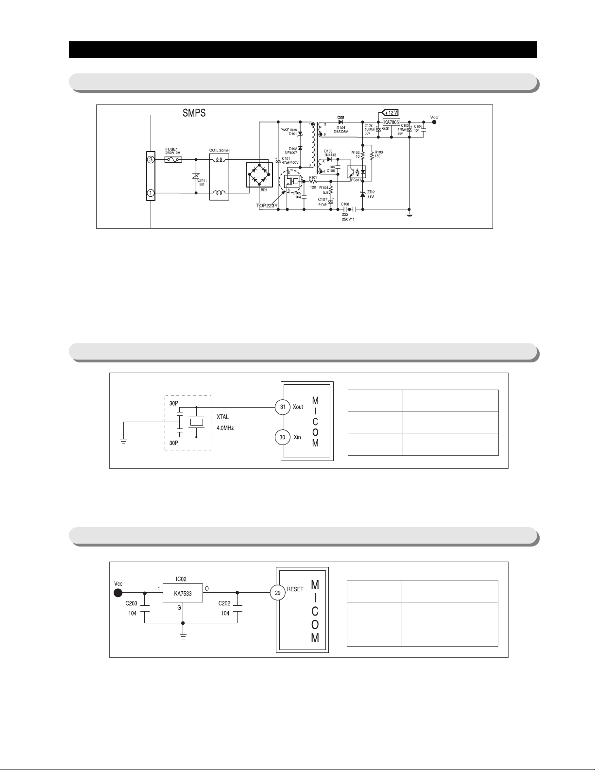
10-1) Source Power Circuit
10-2) Oscillator Circuit
10-3) Reset Circuit
Terminal Oscillation Frequency
Xin(#30)
Xout(#31)
4MHz
4MHz
This circuit shows SMPS(Switch Mode Power Supply) which converts AC input voltage (230V, 50Hz) to a high DC
voltage (about 320V). The input AC source power is converted to DC through a wave rectifier (BD1) and the converted
DC power will generate a constant waveform on the switching transformer using a high speed (100KHz) switching motion
of TOP223Y. The D104 will rectify the generated voltage and transform into a steady 12V DC source power used for the
digital display panel and relays. The regulator (KA7805) finally transforms into 5V DC source power for the control board
and sensor’s circuits.
Caution) Be careful to handle this circuit due to high voltages (AC1 15V, DC170V)
This is oscillator circuit to generate synchronous clocks used to calculate the time for the microprocessor operation.
Note) If the specification of a resonator changes, micro-processor can not work properly .
The reset circuit is to initialize the values RAM & other sectors of micro-processor. When the power is engaged initially,
the reset voltage becomes “Low,” and it keeps “High” in the normal operation.
Terminal Voltage
Vcc
RESET
DC 5V
DC 5V
Page 3
45
Circuit Descriptions
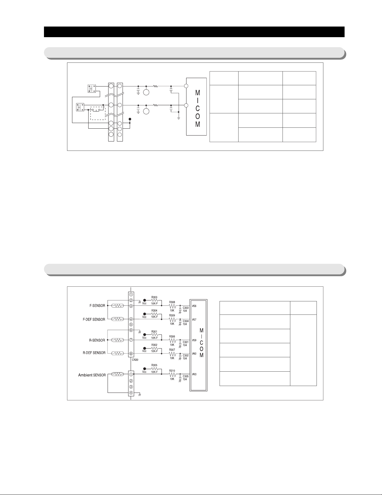
10-4) Door S/W Sensing Circuit
10-5) T emperature Sensing Circuit
1 ) F-Room door open is picked up based on the state (5V/0V) of the MICOM No.43 Port.
When the F-Room door opens, it becomes short between the Door S/W 1 &2.And,5V is supplied in the following
order. CN30 No.⑨→F-Door S/W → CN30 No.①→R408(1 0K)→MICOM 43 PORT
When the state of MICOM 43 PORT is 0V, the door is picked up as closed. When it is 5V, the door is considered to be
open.
2) R-Room door open is picked up based on the state (5V/0V) of the MICOM No.44 Port.
When the R-Room door opens, it becomes short between the Door S/W 1 &2.And,5Vis supplied in the following order .
CN30 No.⑩→R-Door S/W → CN30 No.⑤→R407(1 0K)→MICOM 44 PORT
When the state of MICOM 44 PORT is 0V, the door is picked up as closed. When it is 5V, the door is considered to be
open.
3) When door open is detected, the MICOM have the relevant Fan Motor stop and the relevant Room Lamp light up.
Depending on the state of Door Open/Close, there are following operations; Lamp On/Off, Fan Motor On/Off and Door
open alarm. So, check relevant items upon A/S.
Terminal Operation Volt(state)
Freezer
(MICOM43PORT)
DOOR OPEN
DOOR CLOSE
0V (LOW)
5V (HIGH)
Ref.
(MICOM44PORT)
DOOR OPEN
DOOR CLOSE
0V (LOW)
5V (HIGH)
# of t
erminal in MICOM Remark
PIN #56 (F-SENSOR)
PIN #57 (F-DEF-SENSOR)
PIN #59 (R-SENSOR)
PIN #60 (R-DEF-SENSOR)
PIN #63 (EXT-SENSOR)
Micom
terminal
voltage may
change
according to
temp.
1) A thermistor with a negative temperature coefficient (NTC) is used for a temperature sensor .
2) Resistors, R 306 ∼ R310 and capacitors, C 301 ∼ C 305 are used for a noise protection purpose.
3) For the F-sensor, the input voltage into the micro processor (MICOM), VF is calculated by (Rth x Vcc)/(R303+ Rth),
where Rth is a corresponding resistance to the thermistor’s output (See Ref. 6 in Appendix).
4) The F-Def sensor is connected with a bimetal and a temperature sensor is in parallel. In a normal operation of the
system, the bimetal is on and 0V is input into the micro-processor. During a defrost cycle, the bimetal will be of f from
54℉, and a divided voltage with R304 enter to the micro-processor to keep sensing the set temperature.
CN30
F-DOOR S/W
124
3
R-DOOR S/W
124
3
HOME BAR S/W
W/R
W/B
ORG
S/BLU
SMW250-13 WHT
1
C708
104
5
C709
104
Vcc
9
10
11
R408
C404
10K
R407
104
C403
10K
104
F
R
43
P42
P43
44
Page 4

46
Circuit Descriptions
10-6) Key Scan and Display Circuit
1) Key Scan and display operation.
The model uses a decorder IC which 4 inputs and 9 outputs.
If the IC 9 decorder (TC4028BP) receivesd signals from
MICOM pins (3∼6), an output signal per 2 miliseconds
comes out from Q3, Q41, Q8, Q6, Q9, Q7, Q0, Q2, and Q4
pin in sequence. This signal enters to a driver IC input
terminal of the CoolSelect Zone
TM
PCB and IC5 (TD
62783AP), then approximate 1 1V peaks will generate from an
output terminal as shown on the next page.
Power Freeze
Freezer Temp.
Ice Type
Power Cool
Fridge Temp.
Child Lock
Page 5

47
Circuit Descriptions
The step signals of DC 1 1∼ 12V will be generated periodically. If a sink signal outputs from IC4, DC 11-12V will be
applied to the LED input terminal and sink the LED output terminal to 0V. Therefore, LED will be ON for 2 miliseconds.
2) Key Scan
The 6 step signals, Q6∼Q4 are applied to scan the 6 keys (buttons). When SW6 is pressed, the step signal from Q6
will be reduced to 5V and entered to the MICOM, then MICOM will match a corresponding function for SW6 key .
Page 6

48
1) CoolSelect Zone
TM
display panel and temperature sensor
1-1) CoolSelect ZoneTMis referred to as a storage drawer to implement features of Quick cool, Thaw, and Select (Soft
Freeze, Chill, and Cool).
1-2) CoolSelect ZoneTMhas an additional display panel. Panel LED are off while the doors are closed. When a door is
open, micro-processor senses its signal and LEDs will be on.
1-3) The basic operational principle is the same as the key scan process.
1-4) The additional sensor can measure the temperature of CoolSelect Zone
TM
. This sensor enables to control the
features of CoolSelect Zone
TM
.
2) Damper drive circuit
Circuit Descriptions
10-7) CoolSelect Zone
TM
Panel Circuit
Page 7

49
Circuit Descriptions
10-8) Fan Motor (BLDC) Drive Circuit
2-1) CoolSelect ZoneTMDrawer is controlled by a damper to supply or block cold air. For Quick Cool, the damper will be
close. So cold air is supplied only to CoolSelect Zone
TM
Drawer. For Thaw, the evaporator heater of refrigerator is
ON and the damper is controlled by the refrigerator temperature.
2-2) The stepping motor controlled by a Driver IC T A7774P(IC7) operates the damper. The stepping motor uses 4
combined signals to open and close the damper.
Note) To prevent the malfunction from a high humidity , a DC 12V, 1 watt heater is mounted and activated continuously.
1) Motor drive circuit
1-1) This refrigerator adopts a BLDC motor froeduce energy consumption, Motors of the freezer , refrigerator and the
machine compartment are composed of the BLDC. For RS2533, R-fan is operated by AC 1 15V Motor.
1-2) Voltages between high-speed and low-speed
Note) Under the conditions, the fans will be operated in 2 options, such as High and Low mode. Generally , it is
operated in the High mode during a day time and in the Low mode at night.
Voltage of motor
High
Low
Measure b
(F-FAN)
11.1V
10V
Measure C
(R-FAN)
10V
10V
Measure d
(C-FAN)
10V
8.3V
In the normal operation, MICOM No. 40, 41 and 42 applies a constant frequency; and
MICOM defects the signal to check the failure of motor.
(frequency(Hz)×12 = motor rpm)
Remark
Page 8

50
Circuit Descriptions
10-10) Option Circuit
10-11) Load Drive Circuit
10-9) EEPROM Circuit
EEPROM is semiconductor memory not to be
erased. It can be used in the area of unstable
electric power.
1-3) When the motor rpm is in 600∼700, it will stop automatically and it tries to resume after 10 seconds. If the motor is
not working properly after 5 time trials, it will rest for 10 minutes, then try to resume again. This process will be
done continuously .
Note) If there is an abnormal situation for the motor, the self-diagnostics will show the corresponding LED segment.
1) The control of load in the system is accomplished by the main PCB.
2) Most of relays or SSRs can control the compressor, refrigerator/freezer defrost heater, and several option functions.
3) For the compressor, #18 pin of micro processor signals High (5V). This signal enters #5 pin of IC3 and #14 of output
terminal which have base and collector functions of IC3 turns on and connects the GND. Relay 73 will be grounded
through #14 of IC. Magnetic field will generate so that the second side of RY73 is activated and 115V is supplied to
the compressor. On the other hands, if #18 of micro processor turns Low(0V), #5 of IC3, the current of R Y 73 relay,
and magnetic field will shut down in sequence. A contact point in secondary side of Relay 73 is off. Finally compressor
will stop.
There are a variety of models that have a
different function. A different model can set up to
use option circuit as shown.
X
O
D602
OPTION
CoolSelect Zone
TM
No CoolSelect Zone
TM
Page 9

51
Circuit Descriptions
4) The principles of other loads is the same as 3) item described.
Note) SSR(Solid State Relay) is a kind of Relay .
*COMP. equivalence circuit of drive section
 Loading...