

Page 1

29
9. Operation Function
9-1) Digital Panel ∙∙∙∙∙∙∙∙∙∙∙∙∙∙∙∙∙∙∙∙∙∙∙∙∙∙∙∙∙∙∙∙∙∙∙∙∙∙ 30
9-2) Temperature Control Function
∙∙∙∙∙∙∙∙∙∙∙∙∙∙∙∙∙∙∙∙∙∙∙∙∙∙∙∙ 30
9-3) Power Freeze and Power Cool Functions
∙∙∙∙∙∙∙∙∙∙∙∙∙∙∙∙∙∙∙∙∙ 31
9-4) Child Lock Function
∙∙∙∙∙∙∙∙∙∙∙∙∙∙∙∙∙∙∙∙∙∙∙∙∙∙∙∙∙∙∙∙∙∙ 31
9-5) Ice Water Dispenser Function
∙∙∙∙∙∙∙∙∙∙∙∙∙∙∙∙∙∙∙∙∙∙∙∙∙∙ 32
9-6) C-Fan Motor Delay Function of the Machine Compartment
∙∙∙∙∙∙∙∙∙∙∙32
9-7) CoolSelect Zone
TM
Function ∙∙∙∙∙∙∙∙∙∙∙∙∙∙∙∙∙∙∙∙∙∙∙∙∙∙∙∙∙ 32
9-8) Water Filter Indicator Function
∙∙∙∙∙∙∙∙∙∙∙∙∙∙∙∙∙∙∙∙∙∙∙∙∙∙∙∙ 33
9-9) Ice-Maker Function
∙∙∙∙∙∙∙∙∙∙∙∙∙∙∙∙∙∙∙∙∙∙∙∙∙∙∙∙∙∙∙∙∙∙ 33
9-10) Defrost Function
∙∙∙∙∙∙∙∙∙∙∙∙∙∙∙∙∙∙∙∙∙∙∙∙∙∙∙∙∙∙∙∙∙∙∙ 35
9-11) Forced Operation Function (Pull-down/R-Defrost/R,F-Defrost/Cancellation)
∙ 36
9-12) Sound Function
∙∙∙∙∙∙∙∙∙∙∙∙∙∙∙∙∙∙∙∙∙∙∙∙∙∙∙∙∙∙∙∙∙∙∙ 37
9-13) Exhibition Function
∙∙∙∙∙∙∙∙∙∙∙∙∙∙∙∙∙∙∙∙∙∙∙∙∙∙∙∙∙∙∙∙∙ 37
9-14) Self-Diagnostics Function
∙∙∙∙∙∙∙∙∙∙∙∙∙∙∙∙∙∙∙∙∙∙∙∙∙∙∙∙∙∙ 37
9-15) Load Operation Check Function
∙∙∙∙∙∙∙∙∙∙∙∙∙∙∙∙∙∙∙∙∙∙∙∙∙∙ 37
9-16) Restoration Function for Power Outage
∙∙∙∙∙∙∙∙∙∙∙∙∙∙∙∙∙∙∙∙∙∙ 37
9-17) Set Point Shift Function
∙∙∙∙∙∙∙∙∙∙∙∙∙∙∙∙∙∙∙∙∙∙∙∙∙∙∙∙∙∙∙ 39
9-18) Table of Set Point Shift Function
∙∙∙∙∙∙∙∙∙∙∙∙∙∙∙∙∙∙∙∙∙∙∙∙∙∙ 40
Page 2
30
9. Operation Function
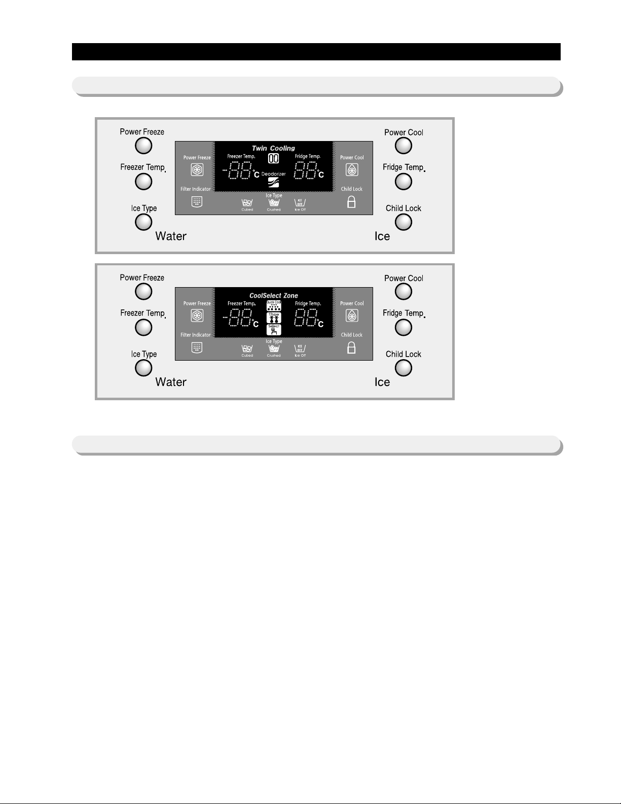
9-1) Digital Panel
When the system power is initally engaged, the default set temper ature are -20 for the freezer and 3 for the set
refrigerator, respectiv ely. The numbers shown on the digital displa y panel stand f or the actual compartments
temperatures. When the compartment temperatures go down, so do the numbers on the display panel, and finally the y
reach the set temperatures. Once the system is stabilized, the displa y temperatures are the set temper ature.
1) Freez er Temperature Control.
To select a set temperature, press the F reez er Temp . b utton. The displa y shows the set temperature from -14 to
-25 in sequence .
2) Refrigerator Temperature Control.
To select a set temperature, press the F ridge Temp . button. The display shown the set temperature from 1 to
7 in sequence.
note) Because of the temperature sensor sensivity, the refrigerator can be under and/or over cooled when
the air flow is block ed b y stored foods . (Temperature range of the sensor :
-930
)
In the event of a po wer f ailure , if the freezer temperature is maintained low er than
5
the last
selected set temperature and functions memorized in EEPROM will be restored when the power is on.
for Dispense Model
for Cool Select
Zone
TM
9-2) T emperature Control Function
Page 3

31
Operation Function
9-3) Power Freeze and P o wer Cool Functions
9-4) Child Lock Function
● Select the Power F reeze or Power Cool buttons separately.
● These buttons are toggled ON and OFF and the indicators as well.
● Although you select Power Freeze or Power Cool, the set temperatures in the freezer and refrigerator are not
changed.
● The set temperatures f or the compartments can be changed while these functions are in use.
1) Po wer Freeze function
1-1) When you press the Power Freeze button, the LED indicator lights right away, but there is 10 seconds lag time
to an actual
operation. When this button is pressed again, the Power Freeze function stops and the indicator is off
immediately .
1-2) If you select P o wer Freeze, both the compressor and the freezer fan run for 10 hours contin uously.
1-3) During Pow er F reez e, the freez er retains the current settings.
1-4) When Po wer Freeze expires, the indicator goes off and the freezer set temper ature will be restored.
2) Po wer Cool function
2-1) Po wer Cool oper ation and the indicator work exactly same as the Power Freez e function.
2-2) When Power Cool is selected, COMP and R-FAN operate continuosly until the refrigerator reaches -4. This
function will be terminated after 2
½ hr running.
3) When you select P o wer F reez e and Power Cool together
Each function works at the same time. The COMP and F-FAN run continuously and the R-FAN runs until -4
in the refrigerator.
4) Initial Po wer-On
4-1) The freezer and the refrigerator temperatures are higher than -10and 10 espectively if, respectively. If Power
Freez e is selected, the R-FAN will be off. If P o wer Cool is selected, the F-FAN will be off.
4-2) When both functions are selected, there is no benefit of fast cooling f or each compartment.
● When the child lock button is pressed for 3 seconds, the child lock indicator is on with an audible tone. when it is
locked, all keys can not be modified except the Ice type button. This function will prevent accidental setting that may
be caused by children or pets. To unlock the setting functions , press this button for 3 seconds again. Also, this button
has another function. When this button is pressed for 3 seconds (lock indication lamp tur n on), the heater for sweat
control is off and all lamps are off except the ice type lamp and child lock indication lamp(But in case of the model
produced before April 2004, all lamps are on)at a same time. If sweat is appeared around the cover dispenser or
beverage station, press this button for 3 seconds again. then, the light will turn off and the sweat control function will
be performed. and all keys will be unloc k ed at a same time.
note) When the Po wer F reez e is selected, it enables maxim um ice maker output. The ice making interval is
reduced from 90 mins to 55 mins (55 mins after the water delivery, if the ice temperature is maintained
lower than -7℃, the ice tray will be twisted). When the ice bucket is full before 10 hours of operation,
Po wer Freeze is automatically terminated.
Page 4
32
Operation Function
9-5) Ice & Water Dispenser Function
9-6) C-Fan Motor Delay Function of the Machine Compartment
9-7) CoolSelect ZoneTMFunction
(RS21K/J, RS23K/J)
● Among several ice-maker functions, the ice e xtr action function is perf ormed by mechanical system. Only the relay
control for a cubed-ice dispensing and the SSR control f or the ice chute door are perf ormed electronically.
1) Select Cubed/Crushed/Ice-off function
1-1) The Ice Type button selects Cubed/Crushed/Ice-off options in sequence.
1-2) A default setting is Cubed option.
1-3) If Cubed ice is selected, the Crushed ice bypass solenoid and the geared motor will allow Cubed ice to by pass
the ice Crusher.
1-4) If Ice-off is selected, the ice maker will stop working. This option will be terminated when Cubed and Crushed
options are selected.
1-5) The ice chute door must be open for 5 seconds after dispensing ceases. After this 5 seconds delay , SSR will be
controlled to shut the ice chute door.
2) Water Dispenser function
2-1) To dispense water , depress the water dispenser le v er located in the dispenser recess .
2-2) When the lever is depressed, the w ater solenoid v alv e located in the machine compartment is open to flow water .
2-3) There is no electronic control function for this option.
● According to the ambient temperature, the condenser fan located in the machine compartment is operated with
different modes.
● T o select this function, open the refrigerator door and press the button on the control panel of CoolSelect Zone
TM
drawer.
● When the CoolSelect Zone
TM
function is selected, the damper inside fan ductwork is open. So the refrigerator cooling
is performed first, then the damper is closed to control the CoolSelect Zone
TM
temperature.
Note) When the Ice-off indicator is on and the remained ice is in tray, only Cubed ice will be dispensed from
the ice bucket.
Note) Do not force to close the ice chute door . Try to dispense some more ice again to work it automatically .
Ranges of ambient temp.
Above 19
16 ~ 18
Below 15
C-F AN is ON as soon as the compressor is on.
C-F AN is ON with 5 min utes dela y from the compressor on.
C-F AN is OFF regardless of the compressor oper ation.
C-F AN
Delay function
Operation
Page 5
33
TRAY-ICE
EJECT-SENSOR
COVER-SENSOR
SCREW
SUPT-RUBBER
FIXER-SENSOR
ICE-WAKER, KIT
EJECT-MOTOR
TEST-SWITCH
LEVELING-SWITCH
GUIDE-ICE
(Lever to check ice full)
KNOB-TOUCH
ICE Full-
SWITCH
1) Select function
1-1) Using Select button, Cool, Chill(-1), and Soft Freeze(-5) options can be selected in sequence. Cool option
maintains a set temperature of the refrigerator.
2) Quick Cool function
2-1) If the Quick Cool is selected, LEDs will flash 60 and Min. The count will be decreased in ev ery minute.
2-2) To cancel this function, press Quick Cool button again or Tha w button or Select b utton. Otherwise , it will be
terminated 60 minutes later automatically.
2-3) After this function ends, this drawer will come bac k to Cool option.
2-4) A defrost cycle will be postponed until Quick Cool option is finished.
3) Thaw function
3-1)When the thaw button is pressed, LEDs will flash 4, 6, 10, and 12 in sequence and Hr.
3-2) The count will be decreased in every hour .
3-3) A cancellation of this function is same as Quick Cool function.
3-4) After this function ends, this drawer will be maintained with -1
3-5) While the compressor is on, this drawer retains a certain temperature and while the compressor is off, the defrost
heater is activated and R-FAN is on with a closed position of the damper.
1) Filter Indicator
1-1)This indicator initally lights in green. The light color will be changed to orange after 5 month operation then to red
at the 6th month. The EEPROM in the control board counts a period of time regardless of a power f ailure.
1-2)To reset the counter and the light color, press Ice Type b utton and Child loc k button f or 3 seconds sim ultaneously.
1-3)If these two buttons are pressed simultaneously f or 5 seconds , this function will cease.
1-4)To restore this function, press these buttons again for 3 seconds .
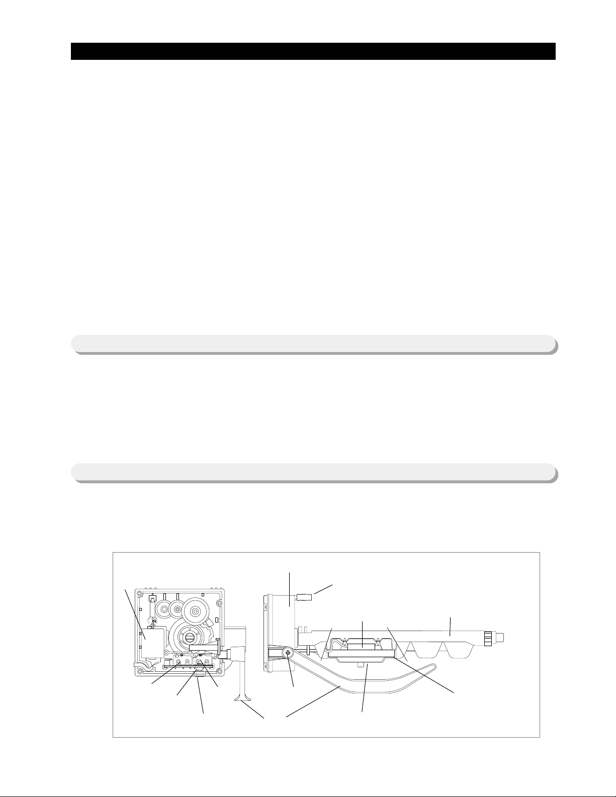
● The Ice-maker is referred to the device with an automatic ice production, storage in the ice buc k et and dispensing
through the ice chute.
1) Ice-maker parts
Operation Function
9-8) Water Filter Indicator Function
9-9) Ice-Maker Function
Page 6

34
Operation Function
<Reference table>
Leveling S/W
ON(“LOW”)
ON(“LOW”)
OFF(“HIGH”)
OFF(“HIGH”)
Ice full S/W
ON(“LOW”)
OFF(“HIGH”)
ON(“LOW”)
OFF(“HIGH”)
Remark
MICOM P ort
PIN #51: Leveling
PIN #51: Ice full
P ort lev el
OFF : 4.5V
ON : 0.5V
Judgement
Not ready
Not ready
Not ready(Ice buck et with full of ice )
Ready
Push the bucket back fully so that the
lever should not be pushed up.
2) Preparation of Ice-maker
2-1) Connect the water line to the water supply valv e of refrigerator to supply w ater . (See ho w to connect a w ater
supply line in the owner’ s manual.)
2-2) Push the buck et back fully so that the guide-ice of ice mak er should not touch the bac k of buc k et. (If the bac k of
buck et touches the guide-ice of ice maker, the ice maker will not make ice any more because of a ice full signal.)
2-3) It takes 6 hours to hav e a first ice, and thro w a wa y 2-3 times of these ice to mak e sure the supplied water clean.
1) Initial Operation function
1-1) Whenever the po wer is on, the control board chec ks the ice tra y le v eling with the le v eling s witch within 2 seconds .
1-2) If the leveling switch is not off position, the geared motor will turn to the initial position to make the ice tra y le v eled.
1-3) When the ice tray is le v eled, it will remain this position f or 2 hours (1 cycle time f or ice production).
1-4) After 2 hours, the sensor located under the ice tra y will measure the tra y temperature . If the temperature is
maintained lower than
-7
for 5 minutes, and the ice full switch is off position, the ice tray twisting process will
begin.
Page 7

35
Operation Function
2) Water Supply function
2-1) When the ice tray is le v eled again after ejecting ice, the w ater solenoid v alue will be controlled to supply water b y
time check basis. (See the “Time to supply water” Tab le)
3) Ice production
3-1) After 90 minutes pass from the water supply, the control board will check the temperature.
3-2) If the sensor reads the temperature lower than -7 f or more than 5 minutes, than the ice production process is
completed.
4) Test function
● In order to operate a test function, press the knob (T est Switch) f or 1.5 second.
● This function can be used to check a proper working, to clean the ice tray, and to adjust the water level in the ice tr a y.
4-1) This function only works when the ice tray is le v eled and the ice full signal is cleared.
4-2) When the water line is connected, each process such as a water supply, ejection, and lev eling, can be in vestigated
by this button.
5) Ice off function
5-1) When the Ice off option is selected by Ice Type button, the ice making process will cease .
5-2) When the ice making process ceases, the final state will be the ice tra y with the supplied water.
5-3) When Cubed or Crushed option is selected again, the control board will check an accummlated time period. After
making it 90 minutes and when the ice tray temper ature is acceptable , ice ejection process will begin.
6) Functions when the freezer door is open
● When the freeze door is open, all ice maker related processes will cease in order to minimize noise and to prevent ice
from dispensing.
6-1) The ice tray stops mo ving regardless of the position.
6-2) The water supply process remains working as usual.
6-3) If the ice tray is in the middle of ice ejecting process, close the freez er f or 30 seconds and chec k if the tra y is
leveled. If it is not leveled, it must be out of order.
1) A defrost is determined based on the accumulated compressor on-time.
2) When the power is engaged for the first time, the defrost cycle for the freezer and the refrigerator will begin after 4
hours of the accumulated compressor on-time.
3) A defrost interval depends on the ambient temperature, the number of door openings, and the door open time .
4) A minimum interval is 6 hours and a maximum is 8 hours for the refrigerator, and 12 hours and 16 hours for the
freezer , respectiv ely.
5) The defrost heater on-time is determined by the defrost sensors as follow :
9-10) Defrost Function
Freezer
Below
10
Refrigerator
17
Heater ON
Heater OFF
-
10
Page 8

36
Operation Function
9-11) Forced Operation Function (Pull-down / R-Defrost / R.F-Defrost / Cancellation)
● This function enables a pull-down mode, a defrost mode for the refrigerator only, a defrost mode for the freezer and the
refrigerator at the same time, and a cancellation of this function.
● Press Power F reeze and Fridge T emp. buttons for 8 seconds simultameously to get in the ready mode f or a f orced
operation.
● The display panel will return to normal after 20 seconds in the ready mode.
● At the ready mode, press any button(except Ice Type and Child Lock) once to start a pull-down operation, twice f or a
defrost cycle for the refrigerator , three times f or a defrost cycle f or the freez er and the refrigerator , and finally four times
for cancellation of this function.
● Another way to cancel this function is to simply plug out and in the power cord.
1) Pull-down Operation
1-1) At the ready mode, press any button once then the b uzzer will beep (ON for 1/2 second and OFF for 1/2 second)
until this mode is cancelled.
1-2) At this pull-down mode, the compressor will start immediately (No 5 minute delay) and if the system is in the
defrost cycle, it will be cancelled right awa y.
Note) If this pull-down mode begins right after the compressor was off, the compressor ma y not start to run due to an
overload condition.
1-3) At this mode, the compressor and freezer f an will operate continuously f or 24 hours and the refrigerator f an will be
on and off according to the set temperature(-20 )
1-4) After 24 hour operation, the system will be cycled at -25 for the freezer and 1 for the refrigerator.
1-5) In order to cancel this mode at any time, select the ne xt mode on the ready mode or pow er off the system.
2) Defrost operation
2-1) At the pull-down mode, press any b utton again on the ready mode to begin the defrost cycle f or the refrigerator .
2-2) The beep sound continues for 3 second at the beginning, then ON f or 3/4 seconds and OFF f or 1/4 second until
this mode cease.
2-3) After this operation, the system will come back to normal operation.
2-4) At this mode, press any button again on the ready mode to oper ate the defrost cycles f or both compartments.
2-5) The beep sound continues for 3 seconds at that time, then ON f or 1/4 second and OFF for 3/4 seconds until the
defrost operation cease.
3) Cancellation
3-1) At the R,F-Defrost mode, press any button again on the ready mode to return to a normal operation.
3-2) Simply unplug the power cord, then plug it again to return to a normal operation.
Page 9

37
Operation Function
9-12) Sound Function
1) Sound function
1-1) To make sure a command input, whenev er a b utton is pressed, a “ding-dong” sounds.
1-2) When two or more buttons are pressed simultaneously or if a wrong b utton is pressed, there is no sound.
2) Door Open Alarm
2-1) When the doors remain open for 2 minutes, there are 10 times beeps .
2-2) If the doors continue to remain open more than 2 minutes, the additional 10 beeps interval will change to 1 minute .
2-3) The beeps will cease immediately when the doors are closed.
● This function is for a display purpose on the floor of show room or store.
1) Mode ON/OFF
1-1) For the e xhibition mode, press Power Freez e and F reez er Temp . b uttons simultaneously f or 8 seconds until a
“ding-dong” sounds.
1-2) Press the same time buttons again for 8 seconds to cancel this mode put with a “ding-dong” sound.
2) Operation
2-1) Most of the system function except the compressor operation are working properly.
2-2) There is no defrost cycle in this mode.
1) Self-Diagnostics in the initial Po wer ON
1-1)The control board performs a self diagnostics test within 1 second and check out the temperature sensors abilities.
1-2) If a sensor failure occurs, a corresponding LED segment will b link with a beep .
1-3) When a LED segment blinks, only the cancellation function (Press Power Freeze and Power Cool buttons
simultaneously for 8 seconds) is acceptab le.
1-4) After a replacement of bad sensor or a cancellation of this function, this self diagnostics will end.
2) Self-Diagnostics in the normal operation
2-1) To select this function, press Po wer Freeze and Pow er Cool buttons sim ultaneously f or 8 seconds with an audib le
tone.
2-2) In the self diagnostic mode, only corresponding LED segments will be illuminated (see the check list on the ne xt
page)
2-3) After a 30 second illumination of error signal, the system will return to the normal operation.
9-13) Exhibition Function
9-14) Self-Diagnostics Function
Page 10

38
Operation Function
Air sensor connector missing; contact
failure, electric wire cut, short-circuit;
open air sensor itself failure; and so on
CoolSelect
ZoneTMsensor
R-DEFROST
ERROR
Ambient Air
SENSOR
Indicate Error when the temperature sensed by
CoolSelect ZoneTMsensor is higher than
65or
lower than -
50.
-
Indicate Error when the temperature sensed by
the open air sensor is higher than
65or lower
than -
50.
FRE sensor connector missing; contact
failed, electric wire cut, short-circuit; FRoom sensor itself failure.
F-SENSOR
Indicate Error when the temperature sensed
by F-sensor is higher than
65or lower than
-
50.
FRE evaporator defrosting sensor
connector missing; contact failed,
electric wire cut, short-circuit; sensor
itself failure; and so on
FRE Defrost
SENSOR
Indicate Error when the temperature sensed by
F-defrosting sensor is higher than 65 or
lower than -50.
F-Fan motor operation failure; feedback
signal line contact failure, motor’s electric
wire missing; and so on.
F-FAN ERROR
Indicate Error if the F and G signals generated by
the FAN-motor operation are not input.
C-Fan motor operation failure; feedback
signal line contact failure, motor’s electric
wire missing; and so on.
In the freezer room, if frost removal mode
is finished due to limited time of 70
minutes. Error is displayed
C-FAN ERROR
(COMP-FAN)
Indicate Error if the F and G signals generated by the
FAN-motor operation are not input
-
F-DEFROST
ERROR
NO Error items LED
Display
Details Remarks
01
02
03
04
05
06
07
08
09
10
11
12
13
I/M-SENSOR
I/M sensor connector missing; contact
failure, electric wire cut, short-circuit; I/Msensor failure; and so on
Indicate Error when the temperature sensed
by I/M-sensor is higher than 65or lower than
-50.
R-SENSOR
REF sensor connector missing; contact
failure, electric wire cut, short- circuit; Rsensor itself failure; and so on
R-Fan motor operation failure; feedback
signal line contact failed, electric wire cut,
short- circuit; and so on
Indicate Error when the temperature sensed
by R-sensor is higher than 65 or lower than
-50
.
Indicate Error when the temperature sensed by R
defrosting sensor is higher than
65or lower
than
-50.
REF DEFROST
SENSOR
REF evaporator internal defrosting sensor
connector missing; contact failure, electric
wire cut, short-circuit; sensor itself failure;
and so on
Indicate Error if the F and G signals generated by the
FAN-motor operation are not input.
R-FAN ERROR
I/M function
ERROR
Ice-ejector and level failed three times
or more
Error items of self-diagnostics
CoolSelect ZoneTMsensor connector
missing; contact failed, electric wire cut,
short-circuit; CoolSelect Zone
TM
sensor itself
failed; and so on.
In the refrigerator room, if frost removal
mode is finished due to limited time of
80 minutes. Error is displayed.
NO Error
ICE-MAKER SENSOR
R-SENSOR
R-DEF-SENSOR
R-FAN ERROR
I/M function error
CoolSelect Zone
TM
SENSOR
R-DEFROST ERROR
EXIT-SENSOR
F-SENSOR
F-DEF ERROR
F-FAN ERROR
C-FAN ERROR
F-DEFROST ERROR
Self-diagnostics check list
If any LEDs blink, the corresponding sensors and
components must be check ed f or an error.
Page 11

39
Operation Function
9-16) Restoration Function for Po wer Outage
9-17) Set Point Shift Function
For the R-FAN, only one rpm is applied for the current models, so that and show R-FAN operation only.
The F-FAN and C-FAN are operated to High/Low rpm automatically according to the operational condition.
and only explain the system operation status according to the ambient condition
1) When the freezer temperature is lower than 5, all functions on the display panel will be restored.
2) When the freezer temperature is higher than 5, all functions will be initializ ed.
(-20 for the freezer, 2 for the refrigerator, and Cubed for the Ice Type)
● Press Freezer Temp. and Power Cool buttons simultaneously for 12 seconds to get into this mode .
● In this mode, only the display LEDs for temperature will be ON.
NO Contents
R-FAN High or AC motor operation
R-FAN Low
R-DEF heater
Start mode
Overload mode
Low-temperature mode
Exhibition mode
COMP
F-FAN High
F-FAN Low
F-DEF-Heater
C-FAN High
C-FAN Low
Dispenser-Heater
Damper
Normal condition
� Table of Load Mode Check List
-
9-15) Load Operation Check Function
1) In the normal operation, press Pow er F reez e and Power Cool buttons simultaneously for 6 second, then the displa y
panel will blink for 2 seconds .
2) Press Fridge Temp . button ⓐ to get into this chec k mode with an audib le tone.
3) Each illuminating LED segment stands for the component which has an ouput signal from the control board.
4) This mode will terminate automatically after 30 seconds.
Page 12

40
1) Shift the freezer temperature sensor
Code
0
1
2
3
4
5
6
7
Temp. shift
Code
Temp. shift
8
9
10
11
12
13
14
15
9-18) T ab le of Set P oint Shift Function
Operation Function
1) Initially, all products set the code, “0” and press Po wer Cool or Fridge T emp . to increase or decrease # of Ref erence .
2) To increase or decrease #of Code,press the P ow er F reez e or Freezer Temp. so that it can be adjusted such as the
temperatures of freezer ,refrigerator,Ice maker,and CoolSelect Zone
TM
,and the quantity of water supply.
3) After 20 seconds from adjustment, a new setting will be stored in EEPROM and return to the normal display.
0
Reference Value
0
0.5
1.0
1.5
2.0
2.5
3.0
3.5
0.5
1.0
1.5
2.0
2.5
3.0
3.5
4.0
Page 13

41
Example) If you are lowering the current temperature of the freezer by
3.0
Code
0
1
2
3
4
5
6
7
8
9
10
11
12
13
14
15
Temp. shift
Code
Temp. shift
2) Shift the refrigerator temperature sensor
Operation Function
Example) If you are raising the current temperature of the refrigerator by
1.5
1
Reference Value
0
0.5
1.0
1.5
2.0
2.5
3.0
3.5
0.5
1.0
1.5
2.0
2.5
3.0
3.5
4.0
Page 14

42
Operation Function
5) Shift the CoolSelect Zone
TM
temperature sensor.
The following options is limited to a model with the Ice Maker.
3) Adjust the time to supply water for the ice
maker
4) Shift the Ice maker temperature sensor
3
Reference Value
0
Code
Time to supply water
5 sec
1
4 sec
2
3 sec
3
6 sec
4
7 sec
5
8 sec
6
9 sec
7
8
9
10
11
12
13
14
15
10 sec
12 sec
13 sec
15 sec
17 sec
19 sec
21 sec
23 sec
25 sec
0
Code
Ice maker
temperature senso
r
1
2
3
4
5
6
7
0
Code
CoolSelect Zone
TM
temperature sensor
1
2
3
4
5
6
7
4
Reference Value
20
Reference Value
-7
-6
-8
-9
-10
-11
-12
-13
0
0.5
1.0
1.5
0.5
1.0
1.5
2.0
 Loading...