

Page 1
MODEL:
RL17MBSW
RL17MBMS
Service Manual
Rifrigerator
Contents
1. Precaution............................................1
2. Specification.........................................5
3. Specification and standard...................6
4. Structure...............................................7
5. Refrigerating circulation diagram..........8
6. Diagram circuit......................................9
7. Operation principle and inspection
method of main parts...........................10
8. Trouble shooting..................................13
9. How to change main parts...................14
10. Parts list.............................................15
Page 2
1. PRECAUTION
1-1. Security
Only the qualified technician who knows the refrigeration circulatory system technology and
rule of security examination, carry on maintenance operation according to the
handbooks.
1-1-1.
1-1-2.
1-1-3.
1-1-4.
Before maintenance, the power plug must be pulled out from socket,
make the refrigerator power cut to avoid human harm and property loss.
If no suggestions from manufactory, don't change the circuit joined and
other operation about circuits change.
Don't use lengthen power line or a pair of wiring boards.
A socket should be grounding and it is not permitted to connect the
grounding line to such places as water telephone line, gas pipeline.
1-2. Precaution
1-2-1.
When change the relay linking with the lead wire on compressor, must
pull out and insert directly. Don't shake the relay from side to side,
otherwise the lead wire on compressor or relay will be damaged.
1-2-2.
!
The refrigerator is restarted at least 5 minutes interval after power off.
If the plug will be inserted at once after the plug pulled off, the
refrigerator can't be started at once .
This is the data correlated with the security of alternating current
circuit and spare parts of refrigerator.
This is the data for maintaining refrigerator.
1
Page 3
1-3.Warning
1-3-1 Pay attention to the safety during maintenance as R600a refrigerant is
combustible and explosive.
1-3-2 Keep the work place well ventilated without fire source and combustible and
explosive objects arround during the maintenance of R600a refrigerator.
1-3-3 Make sure to lay the R600a clean during CYCLE maintenance (ensure the
system unblocked by inflating nitrogen under HV and LV state.)
1-3-4 Fire soldering is not allowed until the work place is ventilative without R600a
left in the CYCLE.
1-3-5 When no leakage and blocking are found by nitrogen inflation, shut the fire by
the soldering fulid pipe (valve core available at one end) at the process pipe.
1-3-6 Adding the fulid by vacuumizing the liquid pipe and screw on the nut.(no fire,
appliance, MP3, walkman and mobile phone are allowed during operation)
Note: LOCK RING is only used for pipe connection rather than pipe sealing after
adding fluid. If special tools are available for liquid releasing, lead the R600a
via pipes to the designated location.
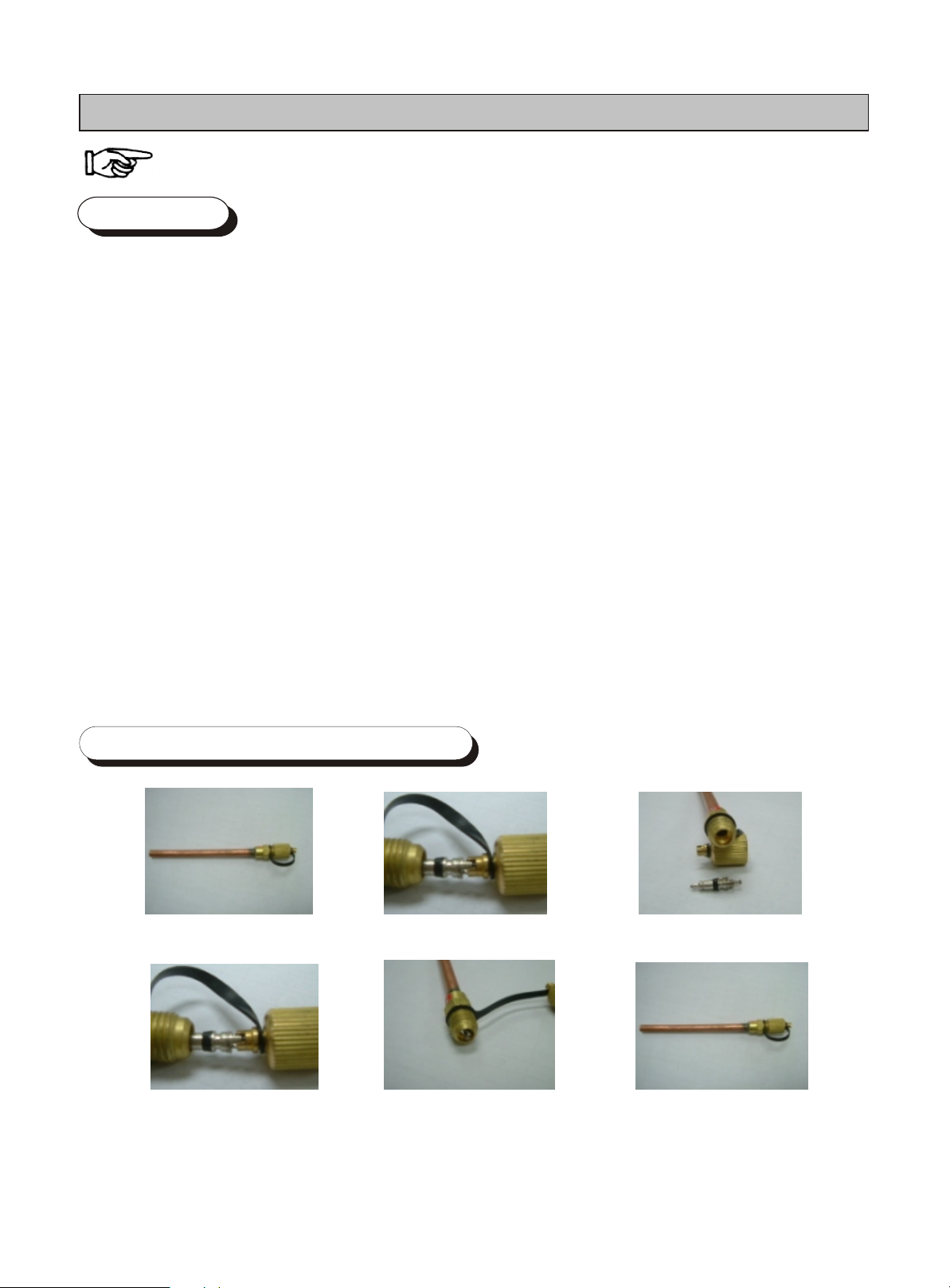
1-4.The special tool for maintaining
1)Liquid Adding Pipe
4) Turn on the valve
core tightly
2)Turn off the valve core
5)Vacuumize and add liquid
3)Solder the pipe onto
the compactor
6) Onload the pipe nut
2
Page 4
1-5.Maintaining Method
1 Maintaining condition
R600a is inflammable and explosive, must take care while maintaining
While maintaining the refrigerating system, there are no flame and
inflammable substance around, keep draughty.
Confirm there is no R600a in CYCLE and keep draughty around,
flaming weld is permitted.
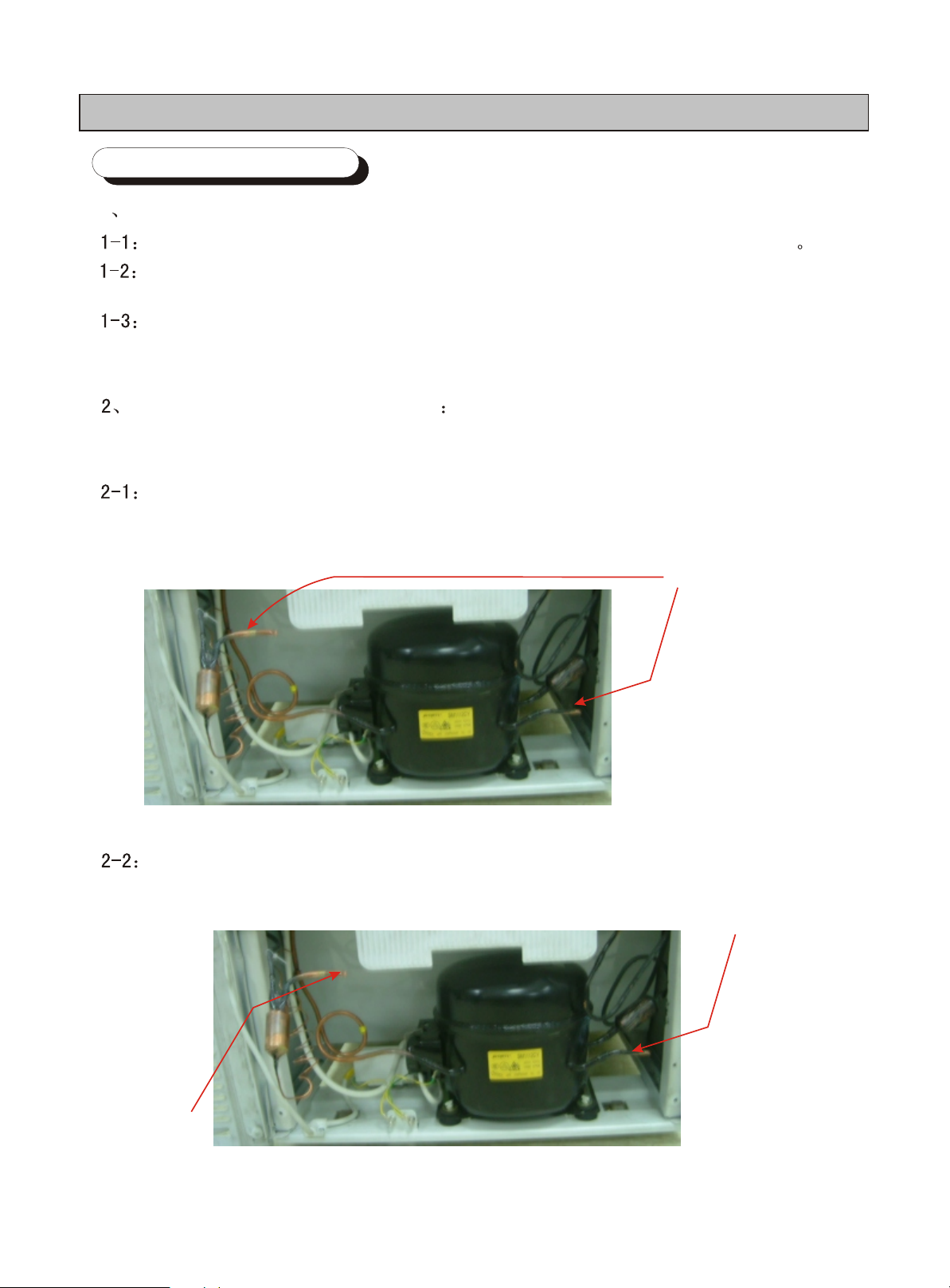
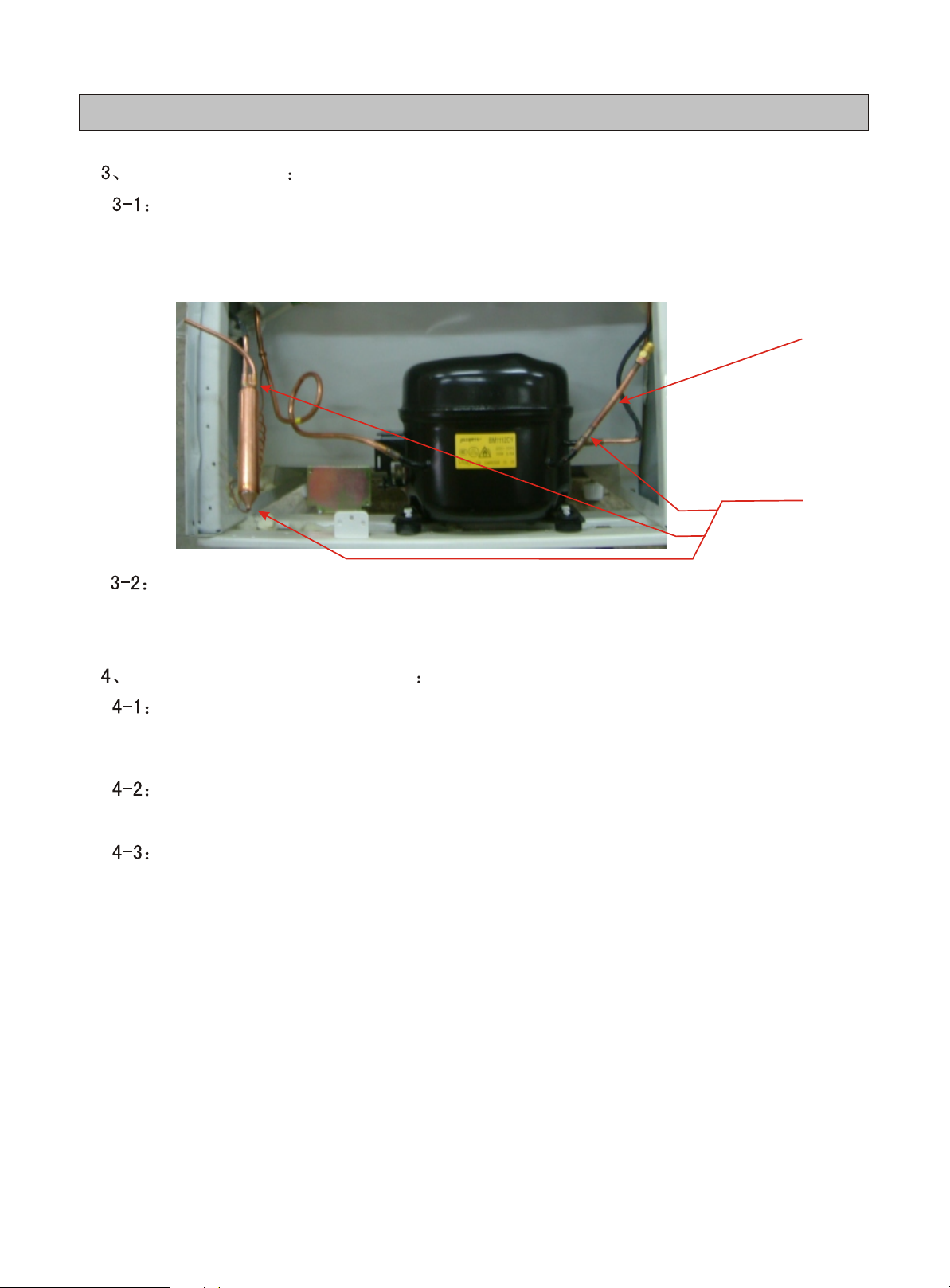
Release the remaining refrigerant
Troubleshooting should be carried on before readding the refrigerant, the
remaining R600a should be discharged outdoor after examining leak.
open the afterward cover of the compressor, pull out two technical
pipes, cut off by vice or knife and discharge the remaining
R600a(figure1).
the spot of cutting
Enter dry nitrogen after setting for some time(about 30 minutes) to
guarantee R600a discharged completely and system unblocked.
enter dry nitrogen
the air is out
3
Page 5
Release vacuum
After discharging refrigerant completely, repair all leaks, change
desiccant and technical pipe, change special pipe for adding refrigerant
on compresso.
special pipe for
adding refrigerant
flame welding
Seal technical pipe in the dry filter, link special technical pipe for adding
refrigerant on the compressor with the vacuum pump and release the
vacuum.
The refrigerant is poured again
After releasing vacuum, the refrigerant R600a is poured into the
charging quantity according to the nameplate, then weigh by electronic
balance.
When filling R600a, the flame is forbidden, don't use mobile phone,
walkman while operating.
After finishing filling refrigerant, screw the pipe bonnet and refurnish the
pipe to prevent from arising the noise.
4
Page 6
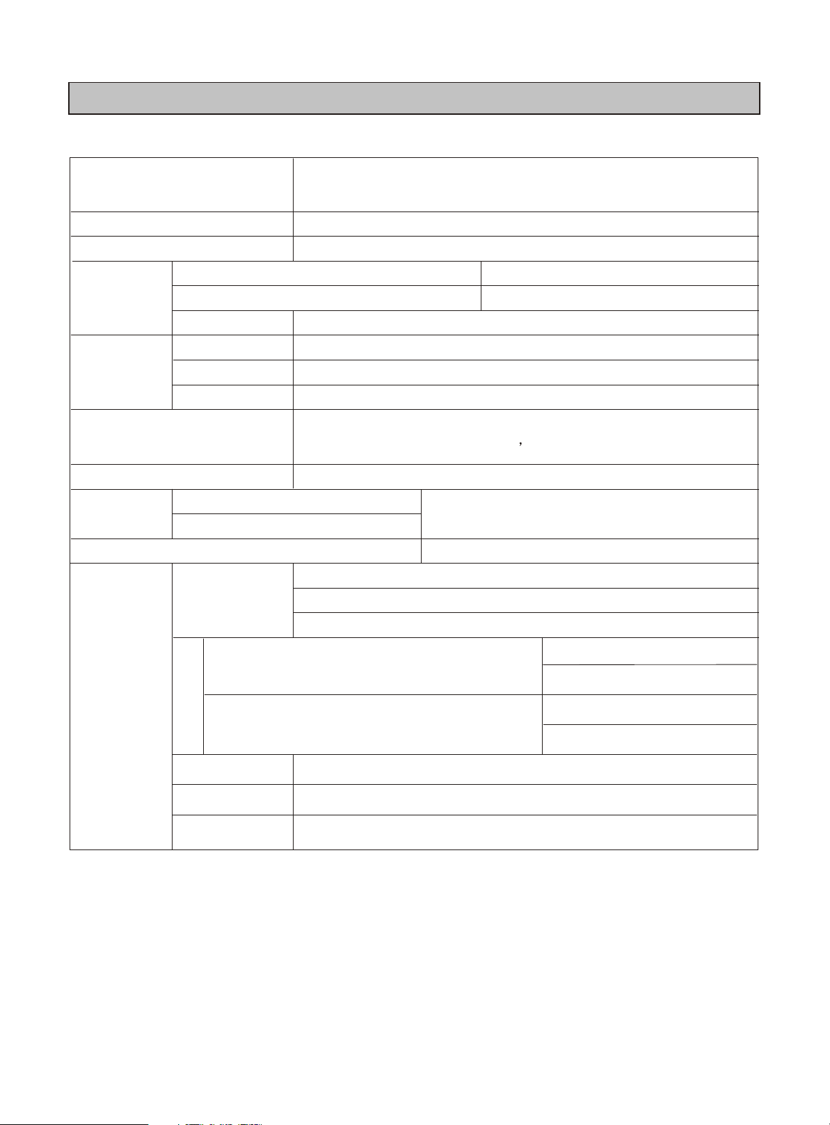
2. Specification
Model
Type
Power
Frozen food storage compartment
Volume L()
Fresh food storage compartment
Total
W(mm)
Dimensions
D (mm)
H (mm)
refrigerant and charging
quantity of refrigerant
temperature control
Foaming
cabinet heatproof thickness
door heatproof thickness
Interior casing door casing/
RL17MBSW RL17MBMS
drawer style and two-door refrigerator-freezer
AC 220/50Hz
54
106
169
451
542
1545
R600a 35g
mechanical controller
Polyurethane foaming
HIPS
egg bin-1
Accessory
Door
Frozen food storage compartment
Fresh food storage compartmen
Cabinet
Lamp
1( )Fresh food storage compartment
Trolley
rectify foot
2 ( )cabinet forehead
bottle rack-3
ice-making case-1
Drawer-3
evaporator part-1
Shelf-4
Crisper-1
2 ( )cabinet rear
5
Page 7

3Specification and standard
Compressor
refrigerating cycle
temperature controller
heat compensatory line
Lamp
door switch
earth screw
Item
Model No
Power
Model No
starting type
lubrication type
Evaporator
Condenser
drier filter
Capillary
Standard
.
AC 220/50Hz
.
SPEC
SPEC
SPEC
BM1112CY
PTC
mineral oil
Tubule
Built-in
molecule filter
Bore 0.65*2800
WDF-31
220V 6W
220V 10W
FN4-0.5/BX
Cu M4*16
RL17MBMSRL17MBSW
electrical appliance system
6
Page 8

4.Structure
Dimension
AA
GG
FF
EE BB C C DD
Model
RL17MB**
Code
¦È¦È
JJ
JGFEDCBA
946.5
7
Unit mm
13854215153080310655451
Page 9

5.Refrigerating circulation diagram
left condenser pipe
Right left condenser pipe
Assistant evaporator part
Molecule drier filter
Silence
Capillary
Asistant evaporator part
Compressor
8
Page 10

6.Diagram circuit
ѹËõ»úѹËõ»úѹËõ»úѹËõ»ú
S
C
3
1
MMMM
M
1~1~1~1~
2
tttt
9
Page 11

7. Operation principle and inspection method of main parts
7-1.Compressor
Operation principle
Compressor motor is assembled with the
compressor directly and sealed in the steel
shell. The motor has two groups of
windings: One is starting winding, another
is operating winding. Two groups of
windings are joined inside and formed a
sharing joint.
A lead is drawn outside from every winding
group. Then three leads are jointed
together in the sealed junction and extend
to the compressor shell.
Three lead junctions form a triangular,
distinguished from left to right indoors
separately: Start junction, share junction
and operate junction.
Inspection method
1 Check the resistance of every
winding group of compressor
. Pull down power wire
. Remove relay from compressor
. Measure resistance of every winding group
A.The Max resistance between start junction
and operate junction is composed of start
winding group and operate winding group.
B.The Min. Resistance is one be
tween operate junction and share junction.
The Mid resistance is one between
C.
start junction and share junction.
B+C=A
2) Put Ohmmeter to the Max measurement
and measure resistance of each junction .
If the short circuit is found, the compressor
is out of order.
7-2.Overload protector
Operation principle
Overload protector protects the
compressor through temperature sensor and
electric current
Overload protector is consist of a group of
closed junction and two metal parts.
Overload protector is installed on
compressor external, connected with the
shell of compressor and linked with the
winding group.
If the compressor isn't work, the overload
electric current will make two metal parts heat
to bend quickly, lead the junction to cut off.
Inspection Method
1 Continue to use the ohmmeter to measure
If the overload protector is off, cooled
to room temperature and measure
continually
Although the working of overload
protector can be observed
continually, it is difficult to confirm
parts working well or not according to
If any question, please change same parts.
Temporal measure should change
regular replacement relay in advance.
10
Page 12

Operation principle
Meanwhile, if the compressor motor is
overheat, the effects of electric current and
temperature will lead two metal parts cut off.
If the troubleshooting isn't settled, the
compressor will be worked or stopped with
two metal parts operation cyclically under the
overload condition.
7-3. Relay
This solid relay is different from mechanical relay, which has no coil and movable
junction.
This relay is consist of a little solid wafer. The solid wafer is low resistance (5~33 )
in room temperature, which is installed between two poles.
Inspection Method
When the voltage is existed in the circuit of compressor, the electric current will
pass operate winding group, relay and start winding group. Firstly, low resistance of
relay can make the enough electric current start compressor by start winding group,
then the relay resistance is increased and electric current is decreased, only tiny
electric current flows relay, which make the relay keep high resistance.
This relay is called PTC relay, the resistance will be increased with the temperature
raise.
Can use the Ohmmeter to check this solid relay. Under the room temperature
condition, the relay resistance should be 10% regular range of refrigerator electric
diagram request.
11
Page 13

7-4 Temperature Controller
Compressor operation is controlled by temperature controller, the temperature
controller is mainly consist of capillary, corrugated pipe, a group of closed junction and
a mechanical link.
The gas pressure in the capillary and corrugated pipe is controlled by
temperature sensor pipe, the temperature raise will cause the corrugated pipe
to push the link and close the junction.
When the temperature is dropped, the corrugated pipe will be shrinked to
push the link and open the junction.
Connect the probe of Ohmmeter with the temperature controller and turn ON
and OFF to check the junction .
12
Page 14

8.Trouble shooting
Another faults, please read “Instruction Manual”
No refrigerating Inspection of refrigerating system( Figure 1)
Normal
No good
Inspection of
compressor
operation
unnormal operation inspection of electrical appliance circuit Figure2
no turning inspection of electrical appliance circuit Figure3
refrigerati
ng
8-1. Troubleshooting Of Refrigerating System
Temperature
controller
unsealed door seal strips
frosted evaporator
Low(high) setting
o f temperature
Unnormal(change)
temperature controller
Inspection Method
After operating for 20 mins. A drop of
water is dropped on the evaporator to
check frosted or not.
Check leak, released vacuum and fill refrigerant
Settlement
8-2. Compressor operation but unnormal . Inspection diagram of electric circuit
Inspection item Reason Settlement
starting power low power
PTC relay damage change relay
Electric conduction test of compressor motor wire is broken Change the compressor
Parts of other electric appliance are normal
The motor and compressor
are damaged
Change the compressor
rising power
8-3.Check electric circuit when the compressor doesn't operate
inspection item Reason Settlement
Power wire, plug the line was broken, or taken off. Repair or change power wire , plug
Electric conduction test of
temperature controller junction
PTC relay damage change relay
Overload protector
Electric conduction test of
compressor motor
The junction is useless,
temperature sensor pipe is
leaked
the junction is useless,
wire is broken inside
Group of compressor motor
13
change temperature controller
Change overload protector
Change the compressor
Page 15

9 How to change main parts
9-1. Change Temperature Controller
1 Pull down the screw fasten light box in temperature controller,
2 Pull down the screw fasten temperature sensor in temperature controller,
3 Pull down connecting line,
4 pull down screw in the shelf of temperature controller.
5 Put out temperature controller.
9-2. Change The Relay
1 pull down fixing button, pull down the relay cover
2 Put down the relay,
9-3. Change Compressor And Drier Filter
Using a knife like welding torch type to cut off the pipe connecting with the
compressor, pull down the connecting line and fasten screw. Then, change compressor.
Notice: when changing compressor, don't let the pipe in flat, otherwise the pipe will be
obstructed .
While linking compressor, the inserted depth should be 6-8mm. While changing filter,
the capillary should be cut off 30mm then insert to the filter, the depth is 13¡À2mm.
After finishing welding, release the vacuum and fill the refrigerant again, the charging
quantity accords with the request on the nameplate and seal the pipe finally.
9-4. Change The Freezing Evaporator
Take out drawer in freezing compartment, pull down the freezing evaporator and put
out the welding joint. Cut off the technical pipe linking with compressor, release
refrigerant , cut off the enter and exit hole of freezing evaporator by welding gun . Pull
out the fasten button of the freezing evaporator, put out the freezing evaporator
,change the new one. After changing, release the vacuum, the charging quantity
accords with the request on the nameplate and seal the pipe.
14
Page 16

10.Parts list
10-1. Parts Of Door
1
5
6
8
9
10
13
2
7
3
4
11
14
15
12
15
Page 17

NO CODE NO PART NAME Q'ty SPEC REMARK
1 DA63-01950C GASKET DOOR-REF 1 160G,SOFT-PVC,-,-,2 DA91-01833J ASSY DOOR FOAM REF 1 WHT,NLO RL17MBSW
DA91-01833K ASSY DOOR FOAM REF 1 SILVER, RL17MBMS
3 DA61-01790C STOPPER DOOR 2 POM,-,-,-, RL17MBSW
DA61-01790D STOPPER DOOR 2 POM,-,-,-,T-S RL17MBMS
4 6002-001111 SCREW-TAPPING 1 TH,+,SJ2823-87,M3.5,L
5 DA97-01751A ASSY SHELF REF 3 139G,PP+GLASS
6 DA63-01942A GUARD EGG 1 GPPS,-,-,-,-,EGG
7 DA63-01945A TRAY EGG 2 GPPS,-,-,-,-,-,8 DA63-01944A GUARD EGG 1 GPPS,-,-,-,-,BOX
9 DA63-01943A GUARD BOTTLE 1 GPPS,-,-,-,-,-
10 DA63-01949A TRAY-VEG 1 GPPS,-,-,-,-,-,11 DA63-01951A GASKET DOOR-FRE 1 139G,SOFT-PVC,-,-,12 DA91-01832G ASSY DOOR FOAM FRE 1 WHT,NLO RL17MBSW
DA91-01832H ASSY DOOR FOAM FRE 1 SILVER, RL17MBMS
13 DA63-02153A TRAY ICE 1 LDPE,-,-,-,-,-,H
14 DA63-01946A TRAY FRE-UPP 2 GPPS,-,-,-,-,-,15 DA63-01948A TRAY FRE-LOW 1 GPPS,-,-,-,-,-,-
10-2. List
16
Page 18

10-3. Parts of Cabinent
8
9
24
4
3
2
1
6
5
7
15
14
13
16
18
19
10
11
12
22
21
20
17
23
17
Page 19

NO CODE NO PART NAME Q'ty SPEC REMARK
1 DA61-01754B CASE THERMO 1 ABS,-,-,-,-,EN
2 DA47-00153A SOCKET 1YUYAO,E14H,HUARI,-,250V,2A,-
3 DA47-00148A LAMP-INCANDESET 1 ,-,-,-,-,-,10
4 DA47-00149B THERMOSTAT 1 RL17MB,WDF31C-L,250V,6A,
5 DA63-01952A COVER LAMP 1 PP,-,-,-,-,-,-,-
6 DA34-00034B SWITCH- SEASION 1 YUYAO,-,ANTI-BLAST,-
7 DA34-00035B SWITCH DOOR 1 FN12-0.5EA,YUYAO,ANTI-B
8 DA63-02154A TRAY DRAIN-WATER 1 HIPS,-,-
9 DA63-01954C COVER COMP 1 PP,-,-,-,-,-,-,- RL17MBSW
DA63-01954D COVER COMP 1 PP,-,-,-,-,-,T- RL17MBMS
10 DA61-01593A HINGE-MID 1 139G,SCP1,-,-,-,-,-,-
11 DA61-01760A STOPPER-R-UPP 2 139/160GY,HIPS,-,-,-, RIGHT
DA61-01759A STOPPER-L-UPP 2 139/160GY,HIPS,-,-,-, LEFT
12 DA61-01761A STOPPER-R-LOW 1 139/160GY,HIPS,-,-,-, RIGHT
DA61-01763A STOPPER-L-LOW 1 139/160GY,HIPS,-,-,-, LEFT
13 DA59-00307A COMPRESSOR 1 220V
14 DA35-00054A RELAY-O/L 1 -,JIXIN JIAXIBEILA
15 DA35-00055A RELAY PTC 1 -,JIAXIN JIAXIBEILA
16 DA62-00690A DRYER 1 CU,-,-,-,-,TAIZHOU KAIDA
17 DA61-01757A BASE-COMP 1 SGCC,1.2,-,-,YE
18 DA66-00280A ROLLER 2 NYLON 1010,-,-,-,-
19 DA61-01755A LEG-ADJUST 2 HARD PVC,-,-,-
20 DA63-01953C COVER-BOTT,FRONT 1 ,ABS,-,-,-,-, RL17MBSW
DA63-01953D COVER-BOTT,FRONT 1 ABS,-,-,- RL17MBMS
21 DA59-00313A EVAP 1 WIRE-PIPE,DW ST,-,-,-
22 DA61-01594A HINGE-LOW 1 SCP1,-,-,-,-,-,-
23 DA39-00284B CBF-POWER CORD 1 RL17MB,UCP2,YUYAO,-,
24 DA64-01138A TOP TABLE 1 ABS,YEL,-,-,-,- RL17MBSW
DA64-01138D TOP TABLE 1 ABS,T-SILVER,-,- RL17MBMS
10-4. List
18
Page 20

 Loading...