How it Works
Log In / Sign Up
Buy Points
How it Works
FAQ
Contact Us
Questions and Suggestions
Users
Samsung
Loading...
R
RFG298AARS
5
RFG298AARS/XAA
4
RFG298AAWP
5
RFG298AAWP/XAA
5
RFG298HD
8
RFG298HDBP
3
RFG298HDBP/XAA
2
RFG298HDBP/XAA-00
RFG298HDPN
2
RFG298HDPN/XAA
RFG298HDPN/XAA-00
RFG298HDRS
3
RFG298HDRS/XAA
RFG298HDRS/XAA-00
RFG298HD SERIES
RFG298HDWP
3
RFG298HDWP/XAA
RFG298HDWP/XAA-00
RFG298HDWP/XAA-01
RFG299A
RFG299AA
3
RFG299AARS
6
RFG299AARS - 29 cu. ft. Refrigerator
4
RFG299AARS/XAA
4
RFG299AARS/XAA-00
RFG299AA series
RFG299ABRS/XAA-00
RFG299XAA series
RFG29PHD
7
RFG29PHDBP
RFG29PHDBP/XAA
RFG29PHDBP/XAA-01
RFG29PHDBP/XAA-02
RFG29PHDPN
RFG29PHDRS
2
RFG29PHDRS/XAA
RFG29PHD SERIES
RFG29PHDWP
RFG29PHDWP/XAA
RFG29THD
8
RFG29THDBP
2
RFG29THDPN
2
RFG29THDRS
RFG29THDRS/XAA-00
RFG29THDRS/XAA-01
RFG29THDWP
2
RFPC012B2M1
RFPC020CBM0
RFPC050H2M0
RFV01U-D1A
2
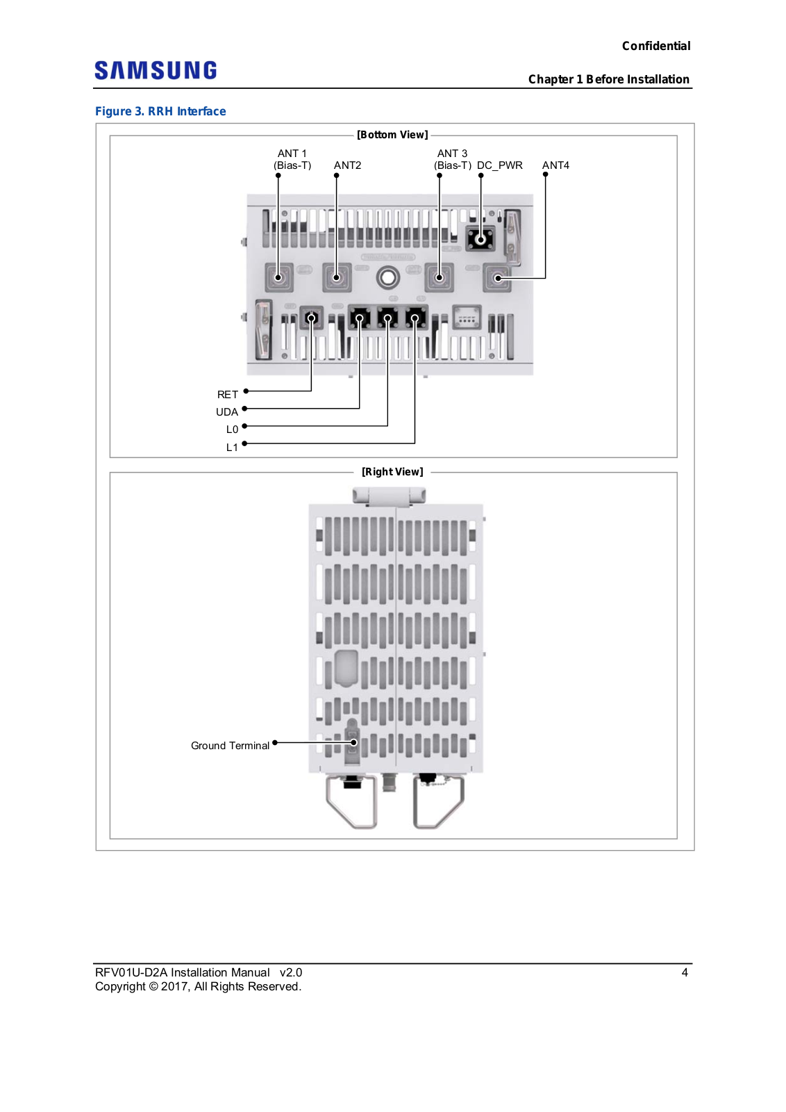
RFV01U-D2A
2
RH22H8010SR
2
RH22H8010SR/AA
rh22h9010sg
3
RH22H9010SG/AA-00
RH22H9010SR
5
RH22H9010SR/AA
2
RH22H9010SR/AA-00
RH22H9010SR/AA-01
RH22H9010SR/AA-02
RH22H9010SR/AA-03
RH22H9010SR/AA-04
RH22H9010SR/AA-05
RH22H9010SR/AA-06
RH22H9010SR/AA-07
RH22H9010SR/AA-08
RH22H9010SR/AA-09
RH22H90 Series
RH22H Series
RH22 Series
RH25H5611
2
RH25H5611BC/AA
2
RH25H5611BC/AA-00
RH25H5611BC/AA-01
RH25H5611BC/AA-02
RH25H5611 Series
RH25H5611SG
3
RH25H5611SG/AA
2
RH25H5611SG/AA-00
RH25H5611SG/AA-01
rh25h5611sr
2
RH25H5611SR/AA
RH25H5611SR/AA-00
RH25H5611SR/AA-01
RH25H5611SR/AA-02
RH25H5611WW/AA
2
RH25H5611WW/AA-00
RH25H5611WW/AA-01
RH25H5613**
RH269LBSH
RH269LBSH/XAA
RH2777AT
RH29H8000SR
RH29H8000SR/AA-00
RH29H Series
RH29 Series
RH 58 K 6598 SL
RH-804
RH-F1204
RH-F1504
Loading...
Loading...
Nothing found
RFV01U-D2A
User Manual
66 pgs
4.48 Mb
0
User Manual
46 pgs
2.54 Mb
0
Table of contents
Loading...
Samsung RFV01U-D2A User Manual
...
Samsung User Manual
Download
Specifications and Main Features
Frequently Asked Questions
User Manual
Download
Loading...
+
46
hidden pages
Unhide
You need points to download manuals.
1 point = 1 manual.
You can buy points or you can get point for every manual you upload.
Buy points
Upload your manuals
 Loading...