

Confidential
Chapter 2 Installing System
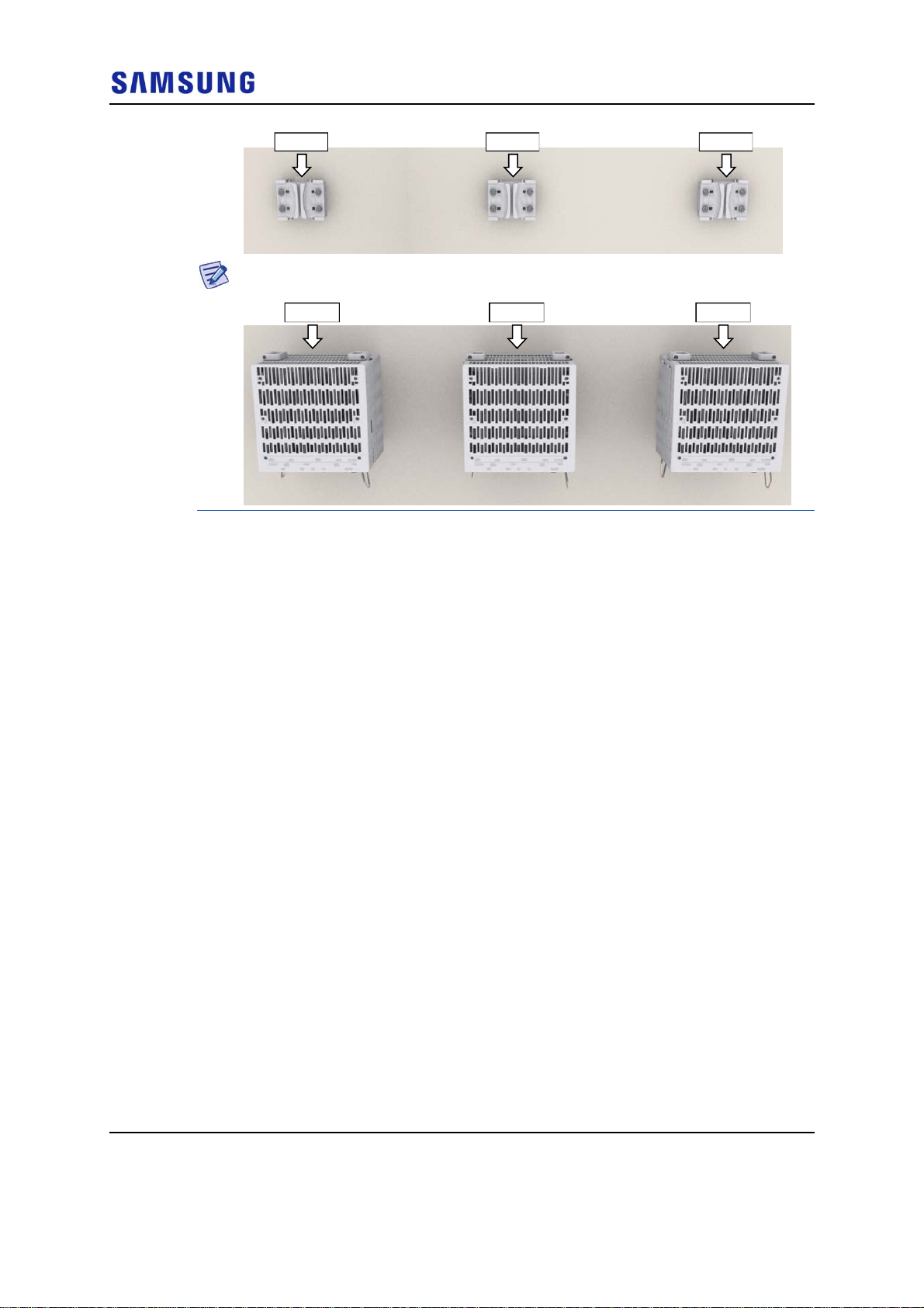
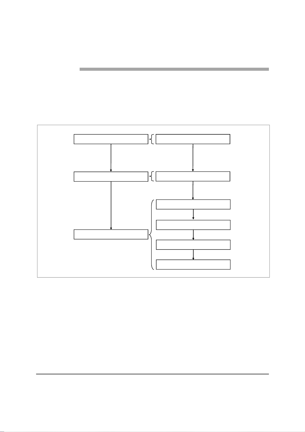
RRH-1RRH-0 RRH-2
Fix the RRH according to the order of [RRH-0 RRH-1 RRH-2].
RRH-1RRH-0 RRH-2
2
Hang the unit bracket hook of RRH-0 side on the mounting bracket_front
hook’s groove and fix it using fasteners.
RFV01U-D1A Installation Manual v2.0 46
Copyright © 2017, All Rights Reserved.
Chapter 2 Installing System
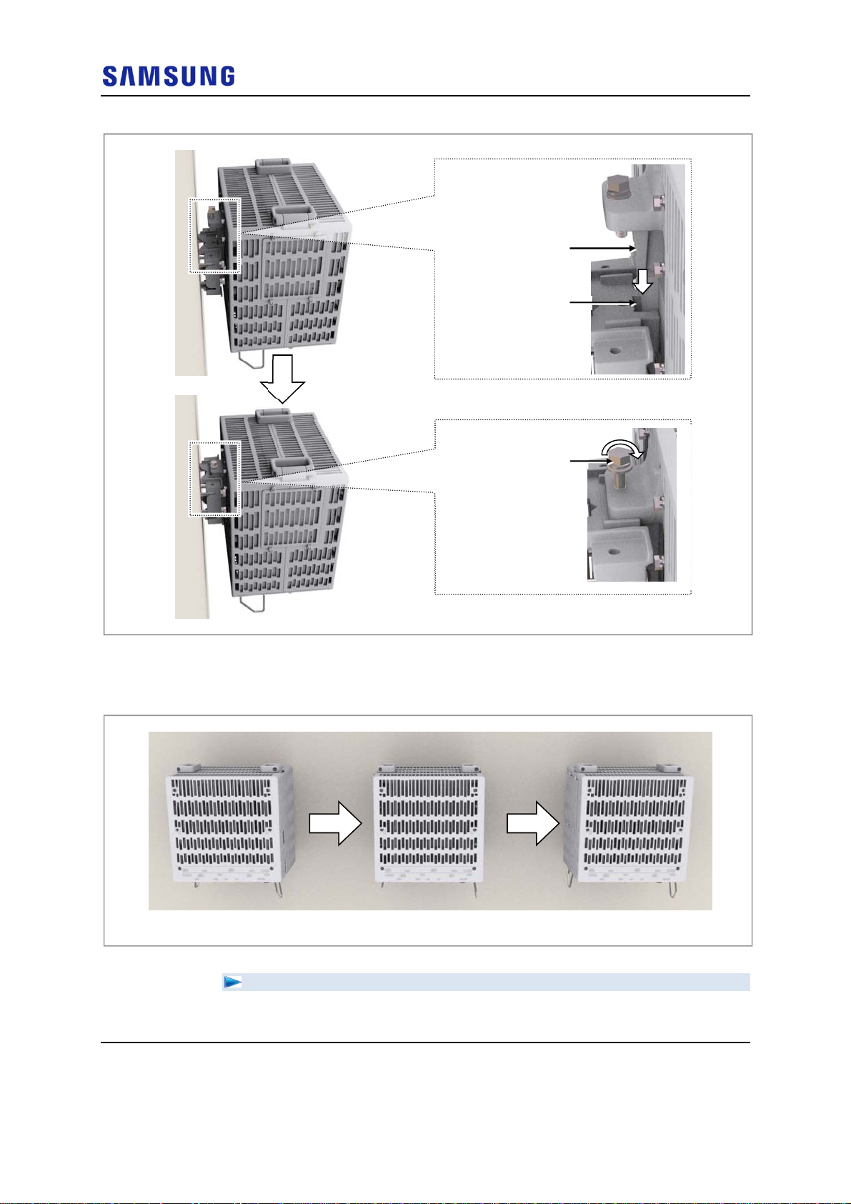
Figure 48. Fixing RRH_3 Sector Wall Type (Standard Installation 1)
Unit Bracket Hook
Confidential
Mounting Bracket_Front
M10 Hex. Bolt
(washer assembly)
3
Fix RRH-1 and RRH-2 in the same way as the RRH-0.
Figure 49. Fixing RRH_3 Sector Wall Type (Standard Installation 2)
Hook Groove
[RRH-0] [RRH-1]
[RRH-2]
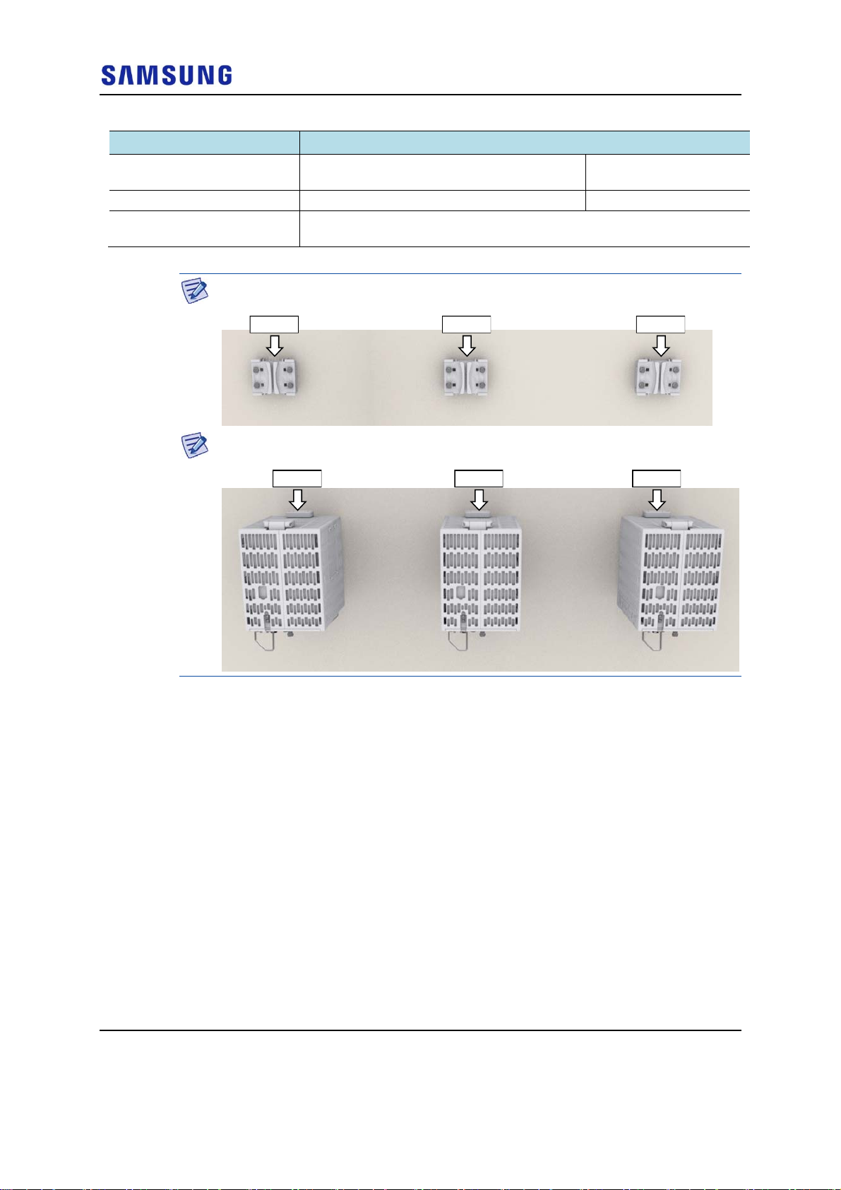
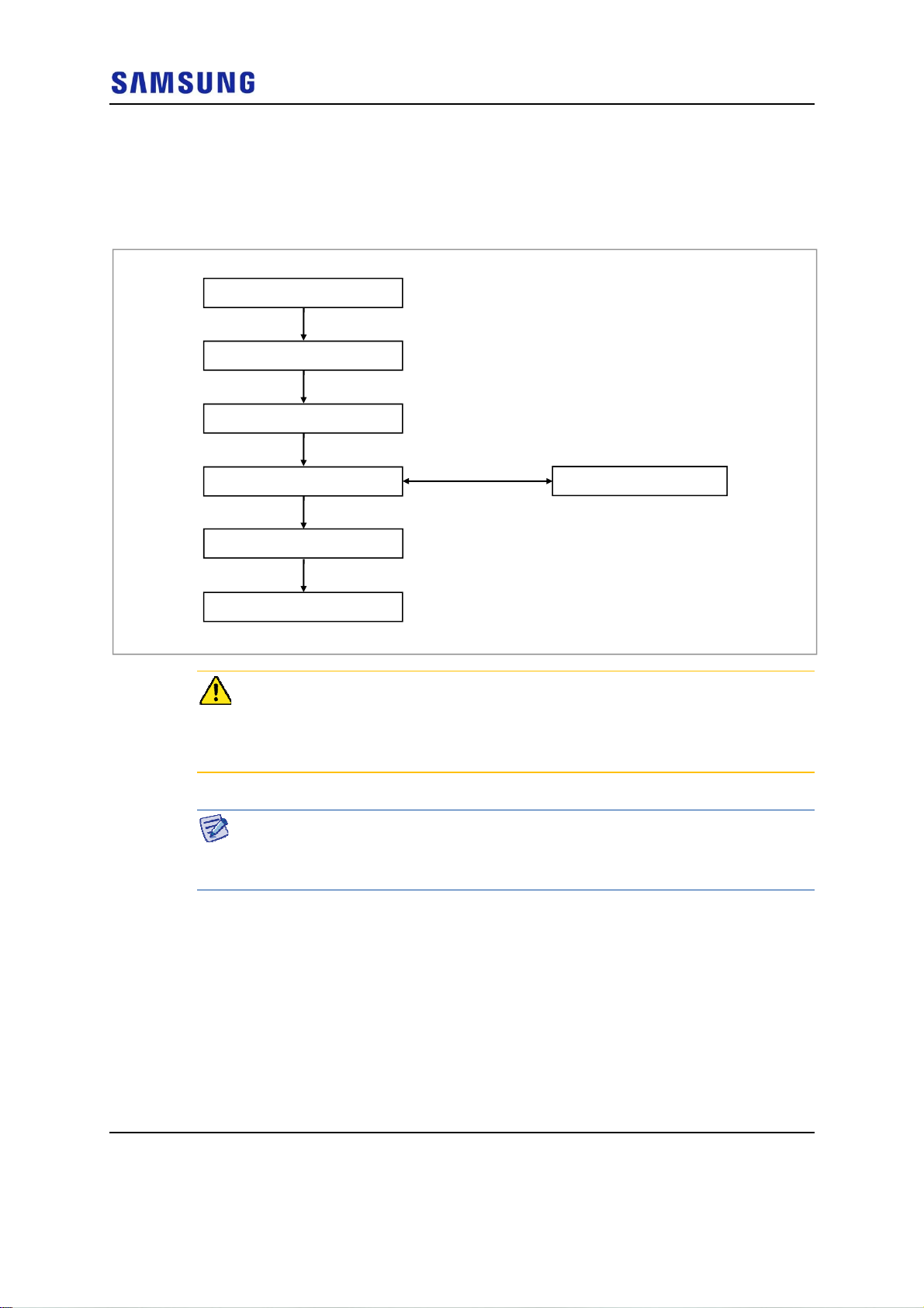
To fix RRH_3 Sector Pole Type (Side Installation)
1
Make sure you have the following items:
RFV01U-D1A Installation Manual v2.0 47
Copyright © 2017, All Rights Reserved.
Confidential
Chapter 2 Installing System
Table 18. Parts and Tools for fixing RRH_3 Sector Wall Type (Side Installation)
Category Description
Parts
Recommended Torque Value M10 Hex. Bolt 217 lbfin (250 kgf·cm)
Working Tools
M10 × 35L Hex. Bolt(washer assembly,
attached to the unit bracket)
Torque Wrench (100~400 lbf·in), Torque Wrench Spanner head (apply Hex.
Head: 17 mm), Spanner (17 mm)
1 EA/RRH
Check the location to install the RRH.
RRH-1RRH-0 RRH-2
Fix the RRH according to the order of [RRH-0 RRH-1 RRH-2].
RRH-1RRH-0 RRH-2
2
Hang the unit bracket hook of RRH-0 side on the mounting bracket_front
hook’s groove and fix it using fasteners.
RFV01U-D1A Installation Manual v2.0 48
Copyright © 2017, All Rights Reserved.
Chapter 2 Installing System
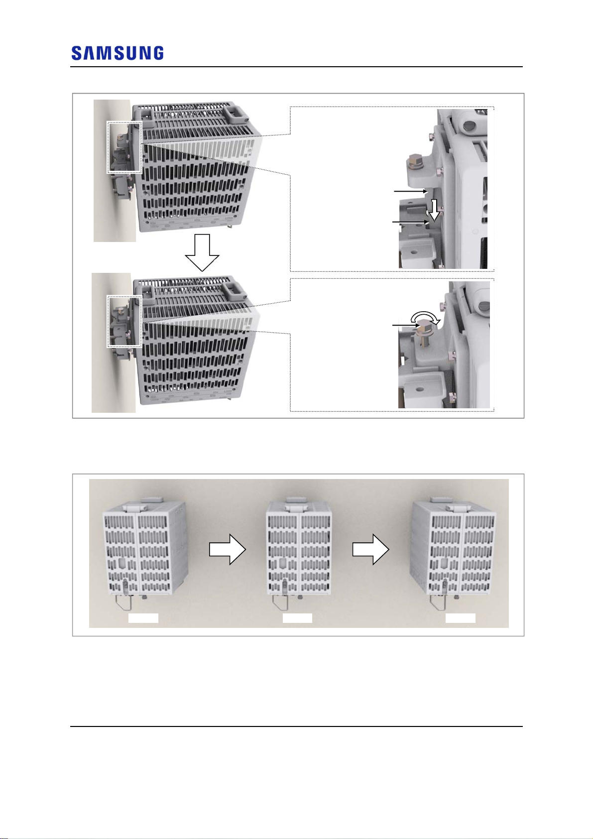
Figure 50. Fixing RRH_3 Sector Wall Type (Side Installation 1)
Unit Bracket Hook
Confidential
Mounting Bracket_Front
(washer assembly)
3
Fix RRH-1 and RRH-2 in the same way as the RRH-0.
Figure 51. Fixing RRH_3 Sector Wall Type (Side Installation 2)
Hook Groove
M10 Hex. Bolt
[RRH-0] [RRH-1]
[RRH-2]
RFV01U-D1A Installation Manual v2.0 49
Copyright © 2017, All Rights Reserved.
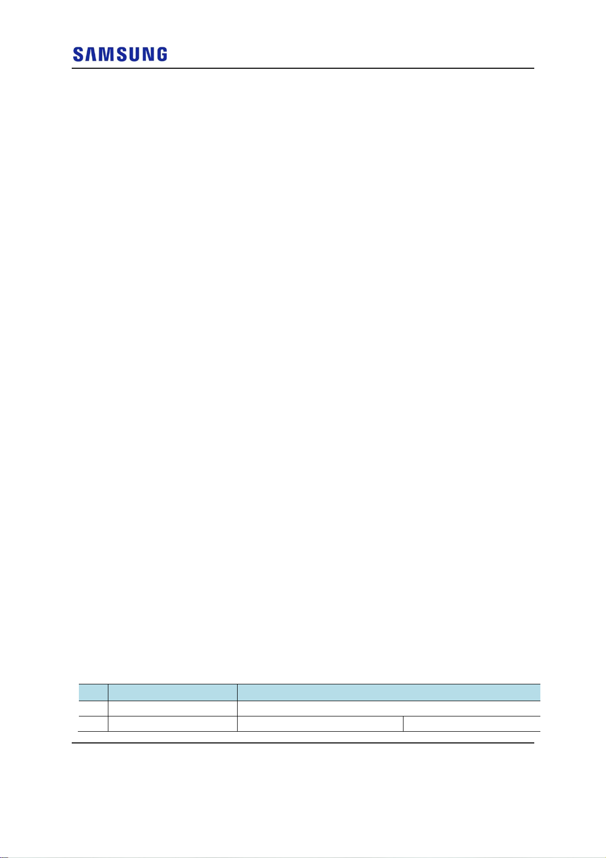
Chapter 3 Connecting
Cabling Procedure
The procedure to connect system cables is as follows:
Figure 52. Procedure to Connect System Cable
Confidential
Cables
Grounding
Power Cabling
External Interface Connection
Ground Cable Connection
Power Cable Connection
CPRI Cable Connection
UDA Cable Connection
RET Cable Connection
RF Cable Connection
RFV01U-D1A Installation Manual v2.0 50
Copyright © 2017, All Rights Reserved.
Chapter 3 Connecting Cables
Guidelines for Cable Connections
The procedure for cable connections is as follows:
Figure 53. Cable Connection Procedure
Cable Path Inspection
Cable Cutting
Cable Installation
When assembling the
Connector Attachment
connector at the site
Connector Assembly
Confidential
Cable Binding
Identification Tag Attachment
When cutting the cable after installation, make sure that the connector is
disconnected. Installation of the cable with the connector connected to the system
may cause contact failure or damage to the connector assembled to the system and
the cable due to cable tension or the operator’s mistakes.
The sequence of cable cutting and installation of the cable workflow can be
changed depending on the field situation such as ‘cutting after installing’ or
‘installing after cutting’.
Cable Path Inspection
When installing a cable that connects between the rectifier, Main Ground Bar
(MGB), and backhaul device, and so on within the system, the cable path, length
and the cable installation method, and so on must be inspected.
Follow these guidelines when inspecting the cabling path.
A minimum cable length must be selected provided that it does not affect the
cable installation and maintenance.
RFV01U-D1A Installation Manual v2.0 51
Copyright © 2017, All Rights Reserved.
The cable must be placed in a location where it will not be damaged by
In areas where the cable may be damaged by external factors, ensure that
Cable Cutting
Measure the exact distance, carefully checking the route, and cut the cable using a
cutting tool.
Follow these guidelines when cutting the cable.
Cut the cable to the length determined in the Cable Path Inspection step.
Use a dedicated cable cutting tool.
Cut the cable at right angles.
Be careful to keep the cable away from any moisture, iron, lead, dust, or other
Confidential
Chapter 3 Connecting Cables
external factors (power line, flooding, footpaths, and so on).
measures are taken to prevent damage to the cable (cable tray, ducts, flexible
pipe, and so on).
foreign material when cutting.
Remove any foreign material attached to the cable using solvent and a brush.
Cable Installation
Cable installation involves running the cable along the cabling path to the target
connector of the system or an auxiliary device after cable path inspection and cable
cutting have been completed.
Follow these guidelines when installing a cable:
Be careful not to damage the cable.
If the cable is damaged, cut out the damaged section before installing, or
replace the cable.
Run the cable so that it is not tangled. In particular, when installing a cable
from a horizontal section to a vertical section, be careful not to reverse the
upper and lower lines of the cable.
Always use the maximum curvature radius possible, and make sure that the
minimum curvature radius specification is complied with.
If the cable needs to be protected, use for example, a PVC channel, spiral
sleeve, flexible pipe, cable rack, and so on.
Install the DC power cable and data transmission cable away from the AC
power cable to prevent electromagnetic induction.
Table 19. Recommended Minimum Allowed Cable bend Radius
No Type Allowed Cable Bend Radius
1 Ground/Power Cable 8 times of the cable external diameter
2 Optical Cable (indoor) Unloaded Condition (Installed)
RFV01U-D1A Installation Manual v2.0 52
Copyright © 2017, All Rights Reserved.
Loaded Condition (During

Confidential
Chapter 3 Connecting Cables
No Type Allowed Cable Bend Radius
: 20 times of cable external diameter Installation)
: 40 times of cable external
diameter
3 Optical Cable (Outdoor) Unloaded Condition (Installed)
: 10 times of cable external diameter
4 UTP/FTP/S-FTP Cable 4 times of the cable external diameter
5 1/2 in. Feeder Line (Flexible) 4.92 in. (125 mm)
※ If the allowed cable bend radius is specified by the manufacturer, comply with the bend radius specified.
Loaded Condition
(During Installation)
: 20 times of cable external
diameter
Cable Binding
Cable binding involves fixing and arranging an installed cable using binding
thread, cable ties, binding wire, and ram clamps, and so on.
Follow these guidelines when binding a cable.
Be careful not to damage the cable during binding.
Use appropriate cable binding tools according to the target location (indoor or
outdoor, and so on) and the type of the cable (power supply cable, optical
cable, feeder line, and so on).
Do not let the cutting section of a cable tie and binding line, and so on be
exposed to the outside. This may cause damage to cables or personal injury.
Make sure that the cutting sections of cable ties and binding lines, and so on
are not exposed to the outside.
Cut off the remainder of the cable thread by leaving about 50 mm of extra
length to prevent the knot from easily getting untied.
If there is a danger that contact failure may occur in a connector connection
due to tension, bind the cable at the closest location to the connector.
Connector Attachment
Connector attachment involves assembling a connector to an installed cable or to a
device on the site.
Follow these guidelines when attaching a connector.
Make sure operator is fully aware of the connector assembly method before
assembling a connector. Assemble the connector in accordance with its pin
map.
Each connector has a hook to prevent its core positions from being changed.
Check the corresponding grooves before connecting a connector to another
connector.
Use a heat shrink tube at a connector connection for cables that are installed
outdoor, such as feeder lines, to prevent water leakage and corrosion from
RFV01U-D1A Installation Manual v2.0 53
Copyright © 2017, All Rights Reserved.
Chapter 3 Connecting Cables
occurring at the part exposed to the outside.
Connect each cable of the connector assembly in a straight line.
Be careful when connecting a cable so that contact failure does not occur at a
connector connection due to tension.
Identification Tag Attachment
Identification tag attachment involves attaching a marker cable tie, nameplate, and
label, and so on to the both ends of a cable (connections to a connector) to identify
its use and cabling path.
Follow these guidelines when attaching an identification tag.
When installing a cable outdoor, use relief engraving and coated labels, and so
on to prevent the markings from being erased.
Since the form and attachment method for identification tags are different for
each provider, consult with the provider before attaching them.
Confidential
When connecting the cables, always connect the ground cable first. If worker
contacts the equipment, connect a cable or perform maintenance without
connecting the ground cable, the system can be damaged or a worker may be
injured due to static electricity and short circuit.
When performing cable work for the system, proceed with the ground work before
any other work to prevent errors occurring due to static electricity and other
reasons.
After completing cable installation, unused port should be capped.
When installing, take care not to overlap or tangle the cables; also, consider future
expansion. Install the DC power cable and data transmission cable away from the
AC power cable to prevent electromagnetic induction.
Make sure the work is done by personnel properly trained for the cabling job.
RFV01U-D1A Installation Manual v2.0 54
Copyright © 2017, All Rights Reserved.
Chapter 3 Connecting Cables
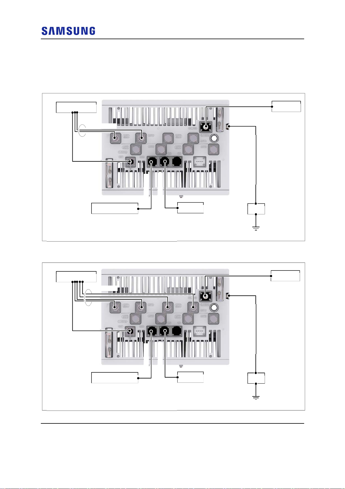
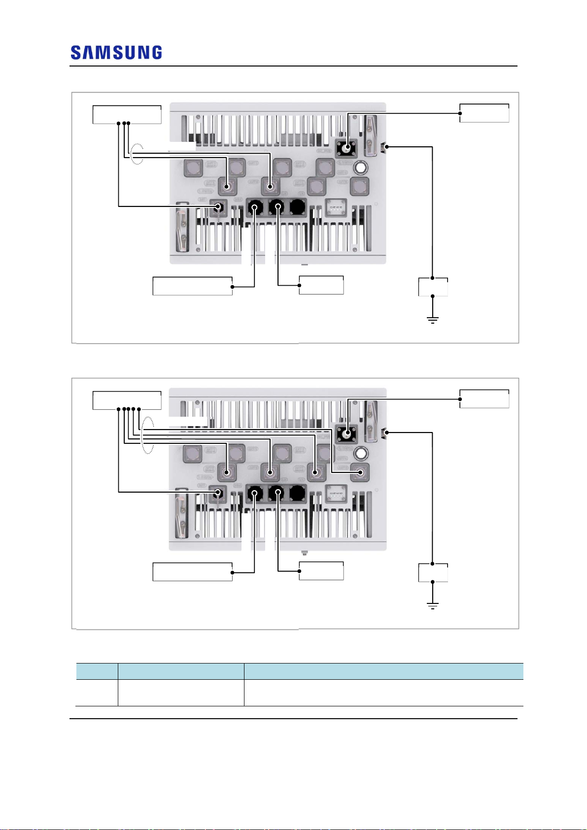
Cabling Diagram
The cabling diagram of the RRH is as follows:
Figure 54. Cable Diagram_2.1 GHz RF Connection: 2T2R
Confidential
RF Antenna
6) RF Cable
5) RET Cable
4) UDA Cable
3) CPRI Cable
External Device
[Bottom View]
* When using the TMA, the RET cables are not connected.
CDU
Figure 55. Cable Diagram_2.1 GHz RF Connection: 2T4R, 4T4R
2) Power Cable
Rectifier
1) Ground Cable
MGB
RF Antenna
6) RF Cable
5) RET Cable
4) UDA Cable
3) CPRI Cable
External Device
[Bottom View]
* When using the TMA, the RET cables are not connected.
CDU
2) Power Cable
1) Ground Cable
MGB
Rectifier
RFV01U-D1A Installation Manual v2.0 55
Copyright © 2017, All Rights Reserved.
Chapter 3 Connecting Cables
Figure 56. Cable Diagram_1.9 GHz RF Connection: 2T2R
Confidential
RF Antenna
6) RF Cable
5) RET Cable
4) UDA Cable
3) CPRI Cable
External Device
[Bottom View]
* When using the TMA, the RET cables are not connected.
CDU
Figure 57. Cable Diagram_1.9 GHz RF Connection: 2T4R, 4T4R
2) Power Cable
Rectifier
1) Ground Cable
MGB
RF Antenna
6) RF Cable
5) RET Cable
4) UDA Cable
3) CPRI Cable
External Device
[Bottom View]
* When using the TMA, the RET cables are not connected.
Table 20. RRH Connection Cable
From To Cable
MGB RRH 1 Ground Cable
: AWG 8 × 1C
CDU
2) Power Cable
Rectifier
1) Ground Cable
MGB
RFV01U-D1A Installation Manual v2.0 56
Copyright © 2017, All Rights Reserved.

Chapter 3 Connecting Cables
From To Cable
RRH Rectifier 2 Power Cable
: AWG 8 × 2C
CDU 3 CPRI Cable
: Single Mode (Outdoor Type)
External Device 4 UDA Cable Assembly
RF Antenna 5 RET Cable Assembly
6 RF Cable
: 1/2 in. Feeder Line
The inlet hole finishing method of external equipment must be progressed after
consultation with operation company in case of the cable connected to external
equipment. (Optical distribution box, etc)
- The Cable: Power Cable, CPRI Cable, UDA Cable
Confidential
RFV01U-D1A Installation Manual v2.0 57
Copyright © 2017, All Rights Reserved.
Chapter 3 Connecting Cables
Grounding
Grounding is the process of operating an electronic system (for example. power
supplying system, communication system, and control system) stably from a
lightning, transient-current, transient-voltage and electric noise and of preventing
injury from electric shock.
Ground equipment minimizes the electrical potential of the electronic device to
that of the ground, which is zero electrical potential, so that it can prevent the
device from occurring electrification.
Connect the ground cable first. In cabling, the connection of cables without the
connection to the ground cable may cause damage of the equipment or bodily
injury to personnel.
The purposes of the ground construction are as follows:
To prevent human life and the system from over-current, over-voltage, and
Confidential
lightning
To provide a discharge path for surge voltage generated by lightning and
power switch
To protect the system from static electricity
To eliminate or minimize the high-frequency potential in the system housing
To provide a conductor for the balance and stability of high-frequency current
To stabilize the potential of the circuit against the ground
Connecting Ground Cable
To connect Ground Cable
1 Make sure you have the following items:
Table 21. Parts and Tools for connecting Ground Cable
Category Description
Installation Section MGB~RRH Ground Terminal
Cable AWG 8 × 1C
Heat Shrink Tube
(Spec/Color/Length)
Pressure Terminal MGB Checking MGB specifications per site and preparing connecting parts
Fastener MGB Checking MGB specifications per site and preparing connecting parts
Recommended
Torque Value
Ф 0.47 in. (12 mm)/Clear/1.96 in. (50 mm)
RRH
RRH M6 × 12L SEMS (Hex. +)/2 EA
M6 SEMS 43 lbf·in (50 kgf·cm)
AWG 8, 2 Hole, Hole diameter:1/4 in. (6.4 mm), Hole spacing: 0.63 in. (16
mm)
RFV01U-D1A Installation Manual v2.0 58
Copyright © 2017, All Rights Reserved.
Chapter 3 Connecting Cables
Category Description
Working Tools
Cable Cutter, Wire Stripper, Crimping tool, Heating Gun, Nipper, Screw Driver (‘+’, No.
3), Torque Driver (20~90 lbf·in.), Screw Driver Bit (‘+’, No. 3 )
For the pressure terminal or the cable, the UL Listed products or equivalent should
be used.
Ex) Manufacturer-Panduit
RRH: AWG8 Pressure Terminal (LCD8-14A-L)
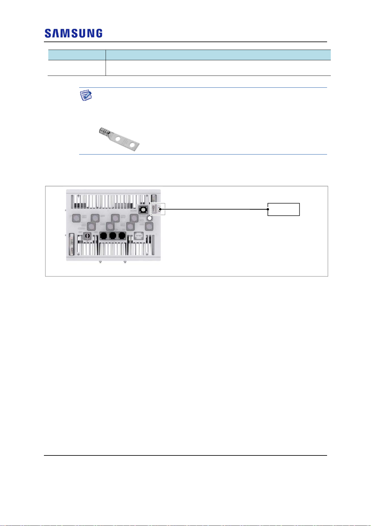
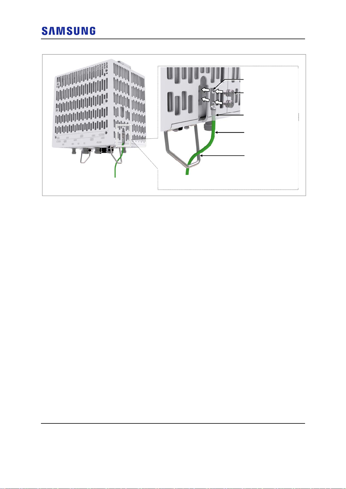
2 Install a ground cable from the MGB to the RRH ground terminal.
Figure 58. Connecting Ground Cable (1)
Confidential
Ground Cable
[Bottom View]
MGB
3 Assemble a pressure terminal and a heat shrink tube at the end of the RRH
ground cable.
4 Align the pressure terminal to the mounting hole of the RRH ground terminal.
5 Firmly fix the pressure terminal onto the RRH ground terminal using fasteners.
RFV01U-D1A Installation Manual v2.0 59
Copyright © 2017, All Rights Reserved.
Chapter 3 Connecting Cables
Figure 59. Connecting Ground Cable (2)
Confidential
Pressure Terminal
M6 SEMS (Hex. +)
Heat Shrink Tube (Clear)
Ground Cable
Support Bracket
* Install ground cable inside support bracket to have it
bound/installed with power cable
RFV01U-D1A Installation Manual v2.0 60
Copyright © 2017, All Rights Reserved.
Chapter 3 Connecting Cables
A
Power Cabling
The power supply device consists of the following elements:
Figure 60. Power Equipment Elements
Confidential
Commercial
Power
AC Distributor
C DC
Rectifier
System
Since power is applied to the system where the power cable is connected by
manipulating the circuit breaker of the rectifier, be sure to check the rectifier’s
breaker is turned off (open) before connecting the power cable to the power
connector. If the system is installed while the circuit breaker is on, the worker may
be critically injured as soon as the cable is connected in the wrong way.
Handling the power cable incorrectly may damage the rack or cause an electric
short-circuit through the cable. Ensure the power switch on the rectifier or the
system is turned off before handling the power.
The fasteners for power cable must be tightly secured to prevent electrical
accidents.
The heat-resistant temperature of the power cable should be 90°C or more.
Install the power cable to the power port of the system by considering the radius of
curvature of its cable specification and then cut the cable. If operator installs the
cable after cutting, there may be length difference among the core wires at the end
of the cable because of cable curvature. This may result in poor contact after the
cable is connected to the power port.
When using the same DC power source with a device for outdoor, discuss with a
installation engineer of manufacturer to protect a CDU from a residual surge
energy.
When using a DC power cable, it is possible to use up to 30 m for AWG 8.
However, the distance is under the condition that the cable is installed normally.
When the condition changes, the distance changes.
Install a circuit breaker to a rectifier (or power distributor) for the stable power.
The capacity of circuit breaker is 40 A. (Use UL Listed circuit breakers.)
RFV01U-D1A Installation Manual v2.0 61
Copyright © 2017, All Rights Reserved.
 Loading...