

Page 1

Fast Track Troubleshooti ng
Model:
RF34H99**/AA
CHECK BULLETIN:
Boards are at the top of this Unit
Control Lock
Control Lock is activated automatically, locking out
all functions to the controls. Press and hold
control lock for 3 seconds before changing any of
the settings or temperatures
FORCE MODE turns compressor on / defrost
Press Freezer and Control Lock
When it blinks let go of buttons and tap on
Control lock again, before display stops blinking
IMPORTANT SAFETY NOTICE – “For Technicians Only” This service data
sheet is intended for us e by persons having electrical, electronic, and mechanical experience
and knowledge at a level generally considered acceptabl e in the appliance repair t rade. Any
attempt to repair a m aj or appliance may result in personal injury and propert y damage. The
manufacturer or seller cannot be responsible, nor ass ume any liability for injury or damage of
any kind arising from the use of this data sheet.
Revision drRF34H Production Date 05/13/2014
Support Information:
HELP: 1-888-751-4086 (Tech S up. – ASC/SSD)
1-866-894-0637 (Tech Sup. - FE/ME)
GSPN: http://gspn3.samsungcsportal.com/main.jsp
PLUS ONE: http://my.plus1solutions.net/clientPortals/samsung
Load Mode used to check what is currently running
Press Freezer and Control Lock
When it blinks let go of buttons and tap on Fridge
DEMO Mode lights remain on but heating and cooling switched off
Press Freezer – Fridge and Control Lock
When O – FF displays you have entered the store demo mode
Heating and cooling will be shut off ( Repeat process to get out of this mode)
Diagnostic Mode shows the errors codes
Press Freezer and Control Lock
Keep holding until display stops blinking, if no
errors recorded the screen will be blank. Wait 30
sec for normal operation
Testing Sparkling Assy this will check the function of the sparkling assy
Open one of the top fridge doors , press and hold sparkling level button for
5 seconds until the operation of the valve is heard. The door must be
open, and the sound will confirm correct operation. Check sparkling assy
voltage for 120V if no Sound is heard, replace if necessary.
Door OPEN press Sparkling Level
Door must be removed a little past
90 degrees
Page 2
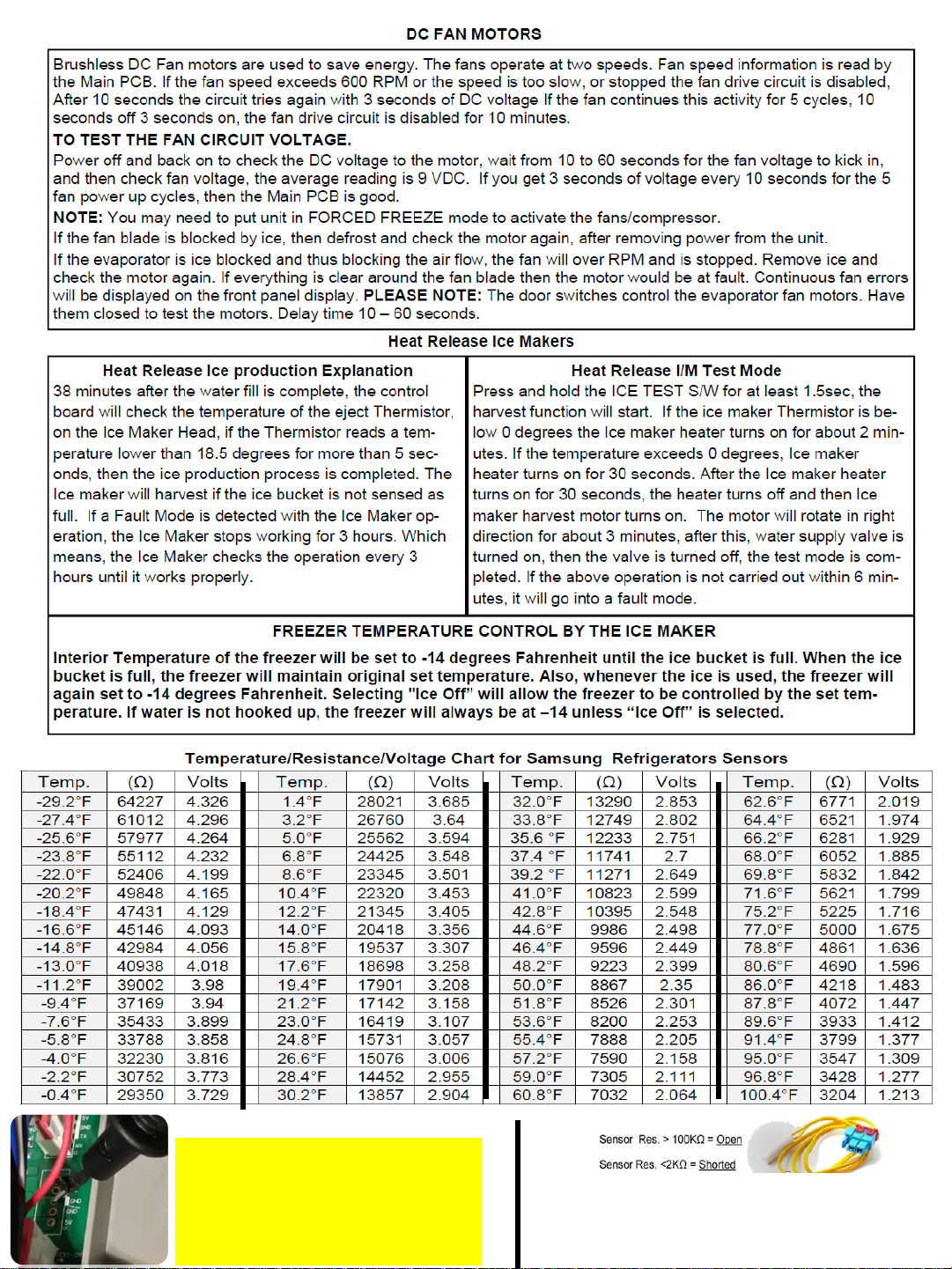
Make sure before measuring voltage of any
DC component that circuit ground is used.
Any marked GND on the main PCB will be
your circuit ground.
If Chassis ground is used, measurements
will be incorrect.
A Sensor Resistance over 100K ohm is considered OPEN
A Sensor Resistance under 2K ohm is considered Shorted
But Note that a sensor could also give wrong values if it is
out of tolerance
Page 3
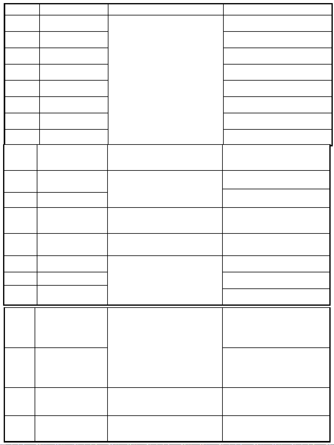
Error Code Item Trouble contents Diagnostic method
1E Freezer Sensor
2E Fridge Sensor
4E
5E
Freezer compartme nt
defrosting sensor
Fridge compartmen t
defrosting sensor
6E External air sensor
7E Pantry Room Sensor
9E Cool Select Room sensor
11E
Cool Select Room defr osti ng
sensor
13E Humidity sensor
14E Ice Maker (Fridge) Sensor Error
15E Ice Room Sensor Error
The sensor housing separating , incomplete contac t,
open-circuited wire, shor t-cir cui t and abnorm al
temperatur e errors are displ ayed when the temperature
measured by the sensor is +50
℃ or higher or -50 ℃ or
lower.
This error is displayed while t he cor resp o nd ing fan
motor is operat ing and a feedback signal line contact
error, motor w ir e separa ti on or mo tor er ror occur s .
Connector Sli pped-Out or Open-Contact, Wire Cut or
Short-Circui ted, Abnormal Sensing Temp : higher than
149
℉(+65℃) or lower than -58℉(-50℃)
The voltage between the Main PCB CN30 pins1 and
8 should be within the 4.5V~1.0V range.
The voltage between the Main PCB CN30 pins3 and
8 should be within the 4.5V~1.0V range.
The voltage between the Main PCB CN30 pins2 and
8 should be within the 4.5V~1.0V range.
The voltage between the Main PCB CN30 pins4 and
8 should be within the 4.5V~1.0V range.
The voltage between the Main PCB CN41 pins1 and
2 should be within the 4.5V~1.0V range.
The voltage between the Main PCB CN30 pins8 and
10 should be within the 4.5V~ 1.0V r ange.
The voltage between the Main PCB CN30 pins5 and
8 should be within the 4.5V~1.0V range.
The voltage between the Main PCB CN30 pins6 and
8 should be within the 4.5V~1.0V range.
The voltage between the Main PCB CN41 pins3
and 4 should be within the 4.5V~1.0V range.
The voltage between the Main PCB CN90 pins3
and 9 should be within the 4.5V~1.0V range.
The voltage between the Main PCB CN30 pins8
and 9 should be within the 4.5V~1.0V range.
16E Fridge humidity sensor
17E Sparkling-Sensor
21E Freezer Fan Error
22E Fridge Fan Error
23E C-Fan Error
24E Freezer Defrosti ng Error
29E
Cool Select Room defr osti ng
Error
31E Cool Select Room Fan Err or
This error is displayed while t he cor resp o nd ing fan
motor is operat ing and a feedback signal line contact
error, motor w ir e separa ti on or mo tor er ror occur s .
Connector Sli pped-Out or Open-Contact, Wire Cut or
Short-Circui ted, Abnormal Sensing Temp : higher than
149
℉(+65℃) or lower than -58℉(-50℃)
The error is displayed while the corresponding fan
motor is operat ing and a feedback signal line contact
error, motor w ir e separa ti on or mo tor er ror occur s .
The separation of the freez er com partm ent defro sti ng
heater housi ng part, contact error, disconnection,
short circuit or tempera tur e f use error . One of these
error codes is displ ayed if t he defr os t ing oper a t i on of
the freezer or Cool Select Room does not fi ni sh even
after the conti nuo us hea t ing oper a ti o n has b een
performed for 120 minutes.
One of these err or codes is displayed in case of the
feedback signal l ine contac t err or , t he mot or w ir e
separation or t he mot or err or when the f an mot or
starts to run.
The voltage between the Main PCB CN30 pins7
and 8 should be within the 4.5V~1.0V range.
The Voltage of ASSY KIT PCB CN32 - "1"
CN32-"3": shall be betwee n 4.5v ~1. 0V
The voltage of the MAIN PCB CN76 1↔4 : should
be between 7V~12V.
The voltage of the MAIN PCB CN76 1↔3 : should
be between 7V~12V.
The voltage of the MAIN PCB CN76 1↔2 : should
be between 7V~12V.
After separat i ng t he MAI N PCB CN70 wir e fr om the
PCB, check the resistance between CN70 7 and 1.
(For the resistan c e val ue, r ef er t o the elect ri c
wiring diagram). For 0 Ohm , check if the heat er i s
short-circuited. For ∞ Ohm, check if the wire or
temperatur e fuse is open-circuited.
After separat i ng t he MAI N PCB CN70 wir e fr om the
PCB, check the resistance between CN70 3 and 1.
(For the resistan c e val ue, r ef er t o the elect ri c
wiring diagram). For 0 Ohm , check if the heat er i s
short-circuited. For ∞ Ohm, check if the wire or
temperatur e fuse is open-circuited.
The voltage of the MAIN PCB CN76 1↔5 : should
be between 7V~12V.
39E
Ice Maker (Fridge) Function
Error
It occurs when t here is a defect in remo ving ice cubes
or in making it paralleled [ When ther e is an error whi le
doing self-diagno sis of the Initial Motor Rotation.]
After replacing the Ice Maker (Fridge), plug in the
Fridge and check if the Ice Maker operates
normally
Page 4

Error Code Item Trouble contents Diagnostic method
40E Ice Maker Fan Error
the Feed Back Signal Wire is defective, the Motor Wire is slipped
out or the Motor is defect ive .
41E Main↔Panel Error A communications er ro r bet wee n t he Mai n and t he Panel PC Bs
When the related Fan Motor operate s, it occurs if the contact of
44E
45E
46E
Main – F Comp. Inverter
Communication Err or
Main – R Comp. Inverter
Communication Err or
I/O Expander
Communication Err or
47E Main↔Dispenser Panel Error
61E Fridge Ice Duct Heater Er ror
Display 44E in the panel :
F Comp. Inverter MICOM ↔ Main MICOM
communication error.
Display 45E in the panel :
R Comp. Inverter MICOM ↔ Main MICOM
communication error.
Display 46E in the panel :
I/O Expander ↔ Main MICOM
communication error.
A communications er ro r bet wee n t he Mai n and t he Dispense r
Panel PCBs
Connector Sli pped-Out or Open-Contact, Wire Cut or ShortCircuited, Defect i ve Thermistor
The error is displayed while the corresponding fan m otor is
62E Pantry Fan Error
operating and a feedback signal l ine contact error, motor wire
separation or m otor er ror occur s
The voltage of the M AIN PCB CN76
1↔6 : should be between 7V~12V.
Since an oscilloscope is required for
the examination, it is recommended
replacing the M ain PCB and then
checking the pr oblem again.
Actually, If there i s not a problem , i t is
desirable to replace Main and Inver ter
PCB With the oscilloscope af ter a
cable problem confirm ing.
It is desirable to replace Main PCB.
Since an oscilloscope is required for
the examination, it is recommended
replacing the M ain PCB and then
checking the pr oblem again.
Remove the MAIN PCB CN51 connec t o r
form the MAIN PCB and read the
continuity between CN51 #6 ↔ contact
point R737 and R776.(Refer to the Block
Diagram for the Resistance Value.
When it reads 0 Ohm, check the Heater
short and when it reads ∞ Ohm, check
if the Wire is open or slipped out.
The voltage of the M AIN PCB CN76
1↔4 : should be between 7V~12V.
65E
Fridge Ice Bucket Heater
Error
Connector Sli pped-Out or Open-Contact, Wire Cut or ShortCircuited, Defect i ve Thermistor
66E Door Handle Heater Error Door Handle Heater Open Error
When the freezer temper atur e is abnormally hi gh or the freezer
door is open for a certain period of time and the freezer
temperatur e incr eases , the fr eezer di splay bli nks.
71E
The F compartme nt abnormal
high-temperat ure indicator
blinks
Remove the MAIN PCB CN51 connec t o r
form the MAIN PCB and read the
continuity between CN51 #7 ↔ contact
point R737 and R776.(Refer to the Block
Diagram for the Resistance Value.
When it reads 0 Ohm, check the Heater
short and when it reads ∞ Ohm, check if
the Wire is open or slipped out.
Remove the MAIN PCB CN51 connec t o r
form the MAIN PCB and read the
continuity between CN51 #2 ↔ CN51
#3(Refer t o the Bl ock D iagr am f or t he
Resistance Val ue.
For ∞ Ohm, check if the wire is opencircuited or not connec te d .
The temperature has been abnormally
increased. Check if the door has been
open for a long time or if hot food has
been stored in the compartmen t. I f the
reason for the er r or is removed , the er ro r
code disappears after a pre-determined
period of time.
Page 5

72E
The R compartment abnorma l
high-temperat ure indicator
blinks
When the freezer temper atur e is abnormally hi gh
or the fridge door is open for a certain period of
time and the fridge t emper at ure increases, the
fridge display blinks.
Check if the d oor has been open for a long time or if hot
food has been stored in the compartmen t. I f the reason
for the error i s removed, t he er ror code disap pears after
a pre-determi ne d per i od of t i me.
81E F Comp start failur e er ror
82E F Comp IPM Fault Error
83E
F Comp location detection error
84E F Comp motor constrai nt er r or
85E F Comp low voltage error
86E F Comp over voltage error
87E R Comp start failur e er ror
88E R Comp IPM fault error
89E
R Comp location detection error
The error code is displayed when the
compressor has failed to start.
The error code is displayed when the
compressor IPM f aul t er r or has occur r ed .
The error code is displayed when the
compressor location detection failed.
The error code is displayed when the
compressor m otor is constrained.
The error code is displayed when the AC Input
Voltage is too low.
The error code is displayed when the AC Input
Voltage is too high.
The error code is displayed when the
compressor has failed to start.
The error code is displayed when the
compressor IPM f aul t er r or has occur r ed .
This error code is displayed when an abnormal
current is detect e d in t he compr e ss or .
Check the soldering status of the inverter PCB. (Check if
any parts have short-ci rcuit ed). Check if the DC 15V
output is less than 13.5V. Check the Comp and Cycle.
Check the compressor wire connecti ons. Check the
soldering status of the inverter PCB. (Check if any parts
have short-circu ited). Check the Comp and Cycle.
Check if the co m pressor and the Cycle is normal.
Check the i n put voltage. Check the soldering of the
inverter PCB. (Check if any parts have short-circuited.)
Check the input voltage. (Thi s error occur s when t he
input voltage i s AC 106 V or lower.)
Check the input voltage. (Thi s error occur s when t he
input voltage i s AC 310V or higher .)
Check the soldering status of the inverter PCB. (Check if
any parts have short-ci rcuit ed). Check if the DC 15V
output is less than 13.5V. Check the Comp and Cycle.
Check the compressor wire connecti ons. Check the
soldering status of the inverter PCB. (Check if any parts
have short-circu ited). Check the Comp and Cycle.
90E R Comp motor constraint error
91E R Comp low voltage error
92E R Comp over voltage error
93E Sparkling Tank Overflow
94E
Water Supply to Sparkling Tank
Error
The error code is displayed when the
compressor m otor is constrained.
The error code is displayed when the AC Input
Voltage is too low.
The error code is displayed when the AC Input
Voltage is too high.
Display error when open err or is detected by
sparkling tank overf low : separat ion of Sparkling
Tank Overflow Sensor housi ng part , contac t
error, disconnect ion , short circui t.
Display error when open err or is detected by
water supply to sparkling t ank error : separation
of Sparkling Tank Water Level Senso r housing
part, contact err or, disconn ect ion, short ci rcuit .
Check if the co m pressor and the Cycle is normal.
Check the i n put voltage. Check the soldering of the
inverter PCB. (Check if any parts have short-circuited.)
Check the input voltage. (Thi s error occur s when t he
input voltage i s AC 106 V or lower.)
Check the input voltage. (Thi s error occur s when t he
input voltage i s AC 310V or higher .)
The voltage of ASSY PCB K IT CN30- “1” CN30-”2”: shall
be over 4.5V
The voltage of ASSY PCB K IT CN31- “1” CN31-”2”: shall
be over 4.5V
Page 6

Load Mode – Unit Function testings
① Freezer + Control Lock Key are pressed simultaneousl y for 6 seconds, ALL ON/OFF will
blink with 0.5interval for 4 seconds.
② If take the finger off from above keys and press Fridge, load condition mode will be
started.
NO Part DISPLAY LED Description
1 R-FAN HIGHEST
R-1-ⓐ,ⓑ
In the case of the R-FAN HIGHEST operation, the cor r espon d i ng LE D is turned on.
2 R-FAN HIGH
3 R-FAN LOW
4 R Comp.
5 Overload
6 Low Temperature
7 Normal
8 Demo Mode
9 PANTRY-FAN
10 Ice maker full
11 F COMP
12 F-FAN HIGHEST
13 F-FAN HIGH
14 F-FAN LOW
15 F compartment defrost heater
16 C-FAN HIGHEST
17 C-FAN HIGH
R-1-ⓐ
R-1-ⓑ
R-1-ⓓ
R-1-ⓔ
R-1-ⓕ
R-1-ⓔ,ⓕ
(ALL LED Off)
R-1-ⓖ
R-10-ⓐ
R-10-ⓓ
F-1-ⓐ
F-1-ⓑ,ⓒ
F-1-ⓑ
F-1-ⓒ
F-1-ⓓ
F-1-ⓔ,ⓕ
F-1-ⓔ
In the case of the R-FAN HIGH operation, the correspond ing LED is turned on.
In the case of the R-FAN LOW operation, the corresponding LED is turned on.
In the case of the R COMP operation, the corresponding LED is turned on.
If the external air temperature is 34℃ or higher, the corres pond ing LED is turned on.
If the external air temperature is 21℃ or less, t he corr esp on d ing LED is turned on.
When the external temper atur e is withi n the range of 22℃ ~ 33℃.
The LED is turned on in Demo Mode.
In the case of the PANTRY-FAN operation, the correspo nding LED is turned on.
When the Ice Maker's Bucket is full , applicable LED ON
In the case of the F COMP operation, the corresponding LED is turned on.
In the case of the F-FAN HIGHEST operation, the corresp ond ing LED is turned on.
In the case of the F-FAN HIGH operation, the correspon ding LED is turned on.
In the case of the F-FAN LOW operation, the corr esp on d ing LED is turned on.
The LED is turned on when the freezer defrosti ng heat er oper at es.
In the case of the C-FAN HIGHEST operation, the cor r espon d i ng LE D is turned on.
In the case of the C-FAN HIGH operation, the correspond ing LED is turned on.
18 C-FAN LOW
19 Dispenser Heater
20 F Valve
21 CV Valve
22 Ice Room-FAN HIGHEST
23 Ice Room-FAN HIGH
24 Ice Room-FAN LOW
25 French Heater
26 CV-FAN HIGHEST
27 CV-FAN HIGH Freezer” for the CV compartme nt In the case of the CV-FAN HIGH operation, the corr es p ond i ng L ED is turned on.
28 CV-FAN LOW
CV compartment defrosting
29
heater
“Freezer” and “Soft Freeze” for the
“Fridge” for the CV com part me nt
F-1-ⓕ
F-1-ⓖ
F-10-ⓑ
F-10-ⓒ
F-10-ⓓ
F-10-ⓓ
F-10-ⓔ
F-10-ⓖ
CV compartment
“Soft Freeze” for the CV
compartment
In the case of the C-FAN LOW operation, the corresponding LED is turned on.
In the case of the Dispenser Heater operat ion, the corresp ond ing LED is turned on.
In the case of the F valve open, the LED is turned on.
If the CV valve opens, the LED i s turned on.
When Ice Room-FAN HIGHEST operate s,
applicable LED ON.
When Ice Room-FAN HIGH operates, applicable LED O N .
When Ice Room-FAN LOW operates , appli cable LED ON.
In the case of the French Heater operatio n, the corr espo nding LED is turned on.
In the case of the CV-FAN HIGHEST operation, the corr espon ding LED is turned on.
In the case of the CV-FAN LOW operation, the correspo nding LED is turned on.
When the CV compartment defros ti ng heate r oper ates ,
the LED is turned on.
Page 7
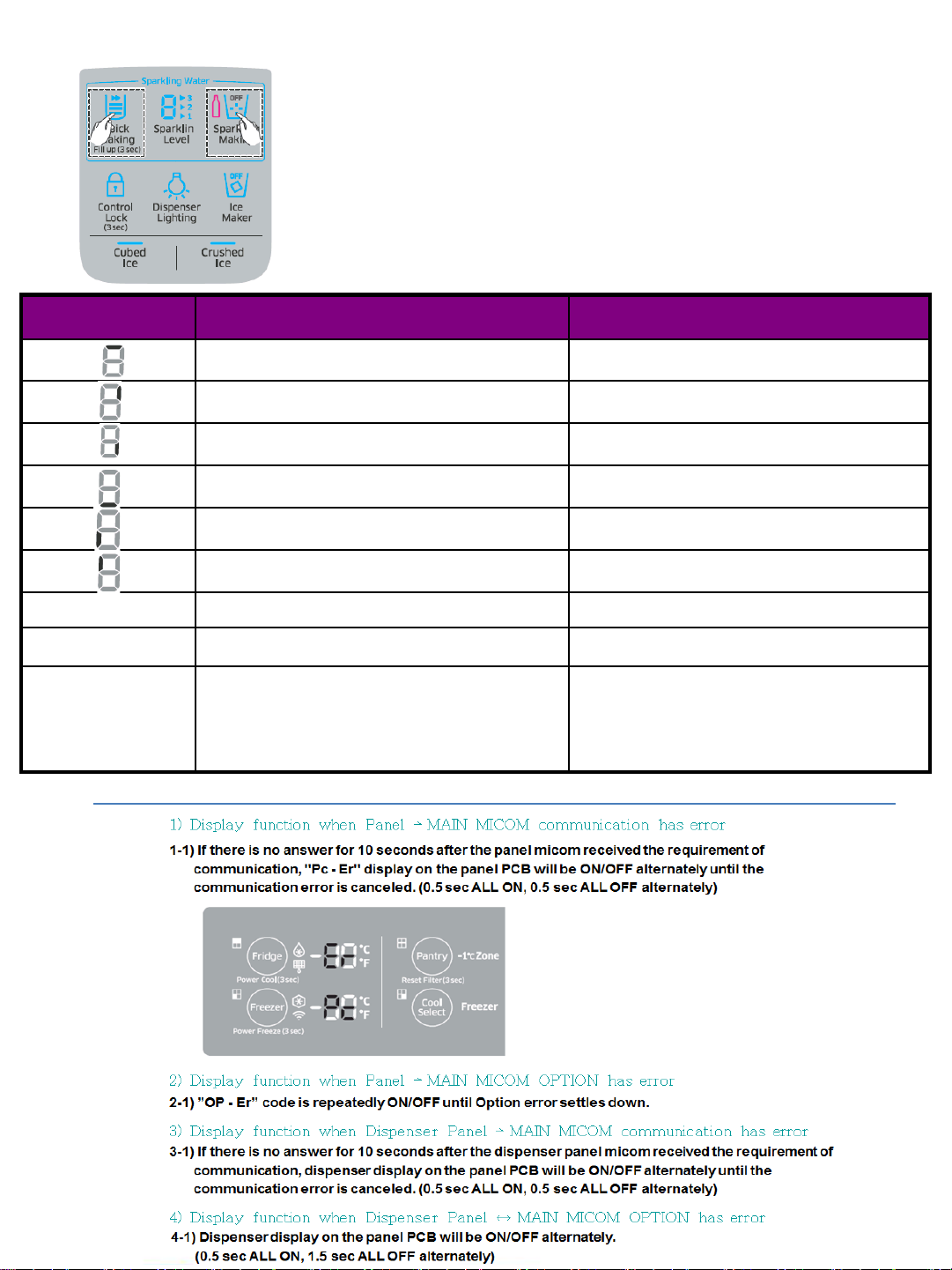
Load Mode – Display Function
1) Quick Making + Sparkling M aki n g key are p ressed simultaneously for 8 seconds
2) Sparkling Load condition display mode shows the load that micom signal is
outputting. However, It means that micom signal is outputting, it does not mean
whether load is operating or not. That is to say that though load operation is
displayed, load could not be operated by actual load error or PCB relay error etc.
(This function would be appl ied at A/S.)
3) Sparkling Load condition display function will maintain for 30 seconds and then
normal condition will be returned automatically.
DISPLAY LED Part Description
Vent Valve When the Vent Valve operates LED Blink
▶ 1
▶ 2
▶1, ▶2
(ALL LED Off)
Sparkling Water To Dispense r Valve
Sparkling Water To Tank Valve When the Sparkling Water To Tank Valve operates LED Blink
Sparkling Water To Dispense r Valve
DC Valve When the DC valve operates LED Blink
CO2 Valve When CO2 Valve operates LED Blink
Sparkling Water Tank Low Detect ion
Sparkling Water Tank Fi ll-Up Detection
Sparkling Water Tank Wat er Level Detect ion : EMPTY
When the Sparkling Wat er To D ispens er Val ve oper a te s LED
Blink
When the Sparkling Wat er To T o Dispense r V alve oper at es LED
Blink
When water is detected by the Water Low Sensor in the
Sparkling Water Tank (W ater i s low), the LED blinks
When water is detected by the Water Fill-Up Sensor in the
Sparkling Water Tank (W ater i s full), the LED blinks.
It is the case in which water is not detected by either the Water
Fill-Up Sensor or the Water Low Senso r in the Spar kli ng Wat er
Tank. It is the condition that it enters the Sparkling Water
Production while the Sparkl ing Wat er Prod uction functi on is
turned on.
Page 8

Page 9
Page 10

If the Failure Condition is detected while the compresso r i s operating, stop the Compr essor operat ing immed iately and wai t for 5 minutes. Dur ing t hese 5
minutes, the RPM command signal is not avai lab le. Even if the RPM command that order s the compr es s o r t o run is sent, th e compresso r does not work and
keep standing by.
The LED is tuned on for 1 second and t hen off for 2 seconds.
The LED blinking frequency depending on the protection functions
If the blinking continues , aft er 5 minu tes, p lease r efer to the r emar ks in t he tabl e above
Sealed System ( 2 compressors )
Door Pin hole Display
.
Display could be removed out from
the top of the door
Page 11
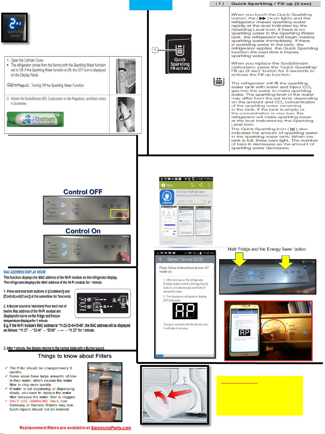
Sparking level, the large number to the left
shows the current setting, the smaller number
on the left shows the next fill setting. During
the next charging process the sparkling level
will charge to that level. Change it to level 1, 2
or 3. Level 1 = 10min charge
Level 2 = 20min charge
Level 3 = 30min charge
Smart Grid
Depending on the energy provider
This option allows the energy provider to shut on or off some
features of the machine during busy times of the day
When Smart Grid override is on the unit will not be
able to communicate with the energy provider
Or – on = Control Off
Or – oF = Control On
Customer Ed info
E – Smart App
This app allows the customer to monitor energy consumption
Connect to the app store (e.g. Google Play, etc.),
search for the app using the “Samsung E-Smart Ref.”
keyword, and download and install the app.
Tip for Customer : If the customer is
having trouble getting the filter back
into the fridge, tell them to turn off
the water supply valve to fridge and
dispense water from the water
dispenser to lower the pressure.
 Loading...