

Page 1
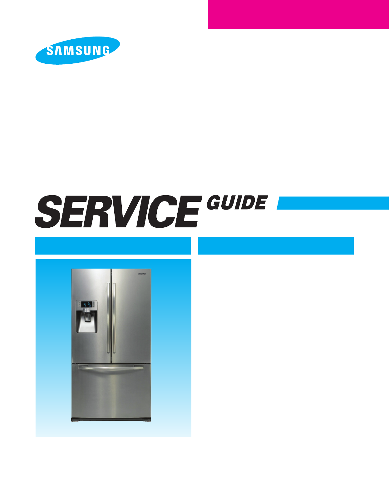
REFRIGERATOR
BASIC : RF267AB
MODEL NAME : RF267ABRS
RF267ABBP
RF267AABWP
RF267ABPN
MODEL CODE : RF267ABRS/ XAA
RF267ABBP/ XAA
RF267ABWP/ XAA
RF267ABPN/ XAA
REFRIGERATOR CONTENTS
1. PRECAUTIONS(SAFETY WARNINGS)··4
2. PRODUCT SPECIFICATIONS
3. DISASSEMBLY AND REASSEMBLY
······························
································
························
RF267AB
4. TROUBLESHOOTING
5 . EXPLODED VIEW & PARTS LIST
6. PCB DIAGRAM
······································
7. WIRING DIAGRAM
8. SCHEMATIC DIAGRAM
················
····
········
7
20
46
83
103
108
109
For the latest parts information, Please access to our service web site
● North America : http://service.samsungportal.com)
(
Page 2
WARNING
IMPORTANT SAFETY NOTICE
The service guide is for service men with adequate backgrounds of
electrical, electronic, and technician experience. Any attempt to repair a
major appliance may result in personal injury and property damage.
The manufacturer or dealer cannot be responsible for the interpretation
of this information.
SAMSUNG ELECTRONICS AMERICA, INC.
Technical Service Guide
Copyright ⓒ2008
All rights reserved. This service guide may not be reproduced in whole or in
part in any form without written permission from the SAMSUNG ELECTRONICS
Company.
Page 3

Contents
1. PRECAUTIONS(SAFETY WARNINGS) ··············································4
2. PRODUCT SPECIFICATIONS ····················································7
2-1) INTRODUCTION OF MAIN FUNCTION
2-2) SPECIFICATIONS ························································10
2-3) INTERIOR VIEWS
2-4) MODEL SPECIFICATION
·······················································11
···················································12
2-5) MODEL SPECIFICATION &SPECIFICATION CHART ·································13
2-6)DIMENSIONS OF REFRIGERATOR (INCHES) ······································16
2-7) OPTIONAL MATERIAL SPECIFICATION ·········································17
2-8) REFRIGERANT ROUTE IN REFRIGERATION CYCLE
2-9) COOLING AIR CIRCULATION
················································19
3. DISASSEMBLY AND REASSEMBLY ···············································20
3-1) PRECAUTION ··························································21
3-2) REFRIGERATOR DOOR
3-3) DOOR HANDLE
·························································24
···················································22
3-4) REFRIGERATOR LIGHT ····················································25
3-5) COVER-DISPLAY & WATER-DISPENSER ········································25
3-6) WATER-DISPENSER ······················································26
3-7) GLASS SHELF
3-8) FOLDABLE GLASS SHELF
··························································27
·················································· 28
3-9) VEGETABLE & FRUIT DRAWERS SHELF ········································28
3-10) COOL SELECT PANTRY ··················································29
3-11) WATER TANK ·························································30
3-12) MOTOR DAMPER ······················································· 32
3-13) WATER FILTER (DISASSEMBLY) ·············································32
3-14) WATER FILTER (REASSEMBLY) ·············································33
3-15) VERTICAL HINGED SECTION ···············································33
3-16) VERTICAL HINGED SECTION ···············································34
3-17) EVAPORATOR COVER IN REFRIGERATOR ······································35
3-18) EVAPORATOR IN REFRIGERATOR ···········································36
3-19) FREEZER DOOR
3-20) PULL OUT DRAWER
························································37
·····················································38
3-21) ICE-MAKER ···························································39
3-22) FREEZER LIGHT ·······················································40
3-23) DOOR SWITCH IN FREEZER ················································40
3-24) EVAPORATOR COVER IN FREEZER ···········································41
3-25) EVAPORATOR IN FREEZER ················································41
3-26) MACHINE COMPARTMENT ·················································42
3-27) ELECTRIC BOX
························································45
···········································8
·································18
4. TROUBLESHOOTING
························································46
4-1) FUNCTION FOR FAILURE DIAGNOSIS ··········································47
4-1-1. TEST MODE (MANUAL OPERATION / MANUAL DEFROST FUNCTION) ··················47
4-1-2. DISPLAY FUNCTION OF COMMUNICATION ERROR ······························48
4-1-3. SELF-DIAGNOSTIC FUNCTION ···········································49
4-1-4. DISPLAY FUNCTION OF LOAD CONDITION
4-1-5. EXHIBITION MODE SETTING FUNCTION
···································52
·····································53
4-1-6. OPTION SETTING FUNCTION ············································53
4-1-7. OPTION TABLE ······················································56
Page 4

Contents
4-2) DIAGNOSTIC METHOD ACCORDING TO THE TROUBLE SYMPTOM(FLOW CHART) ············57
4-2-1. IF THE TROUBLE IS DETECTED BY SELF-DIAGNOSIS
4-2-2. IF FAN DOES NOT OPERATE ·············································68
4-2-3. IF ICE ROOM FAN DOES NOT OPERATE ·····································69
4-2-4. IF ICE MAKER DOES NOT OPERATE ········································70
4-2-5. IF DEFROST DOES NOT OPERATE (F,R DEF HEATER)
4-2-6. IF POWER IS NOT SUPPLIED
············································72
4-2-7. IF COMPRESSOR DOES NOT OPERATE ·····································73
4-2-8. WHEN ALARM SOUND CONTINUOUS WITHOUT STOP(RELATED WITH BUZZER SOUND) ····74
4-2-9. IF PANEL PCB DOES NOT WORK NORMALLY ··································76
4-2-10. IF PANTRY PANEL PCB IS NOT WORKING NORMALLY ···························77
4-2-11. WHEN REFRIGERATOR ROOM LAMP DOES NOT LIGHT UP ·······················78
4-2-12. IF ICE WATER IS NOT SUPPLIED ·········································79
4-2-13. IF WATER IS NOT SUPPLIED ············································80
4-2-14. IF CUBED OR CRUSHED ICE IS NOT SUPPLIED ·······························81
4-2-15. IF COVER ICE ROUTE MOOR(GEARD MOTOR) IS NOT WORKING NORMALLY
····························58
···························71
···········82
5 . EXPLODED VIEW & PARTS LIST
················································83
5-1) FREEZER ·····························································84
5-2) REFRIGERATOR ························································87
5-3) CABINET ·····························································91
5-4) DISASSEMBLY OF FREEZE DOOR ············································95
5-5) DISASSEMBLY OF REFRIGERATOR DOOR LEFT ··································98
5-6) DISASSEMBLY OF REFRIGERATOR DOOR RIGHT ·································101
6. PCB DIAGRAM ···························································103
6-1) PCB LAYOUT WITH PART POSITION ··········································104
6-2) PCB LAYOUT WITH PART POSITION (SMPS BOARD) ·······························105
6-3) CONNECTOR LAYOUT WITH PART POSITION (MAIN BOARD) ·························106
6-4) CONNECTOR LAYOUT WITH PART POSITION (SMPS OARD) ··························107
7. WIRING DIAGRAM ·························································108
8. SCHEMATIC DIAGRAM ······················································109
8-1) WHOLE BLOCK DIAGRAM
8-2) CIRCUIT DIAGRAM
······················································110
·················································109
Page 5
1. PRECAUTIONS(SAFETY WARNINGS)
●
Before servicing the refrigerator or replacing parts, unplug the unit from the
wall outlet.
→
Shock Hazard, observe basic safety rules.
●
Be sure to use the specified generic parts when servicing the product.
→
Confirm the Model Number on Product itself.
Inspect the mew part and assembly for Voltage, Current and temperature
specifications.
●
During the Diagnostic and Troubleshooting phase it is recommended to do a
visual inspection of all the connections of the wiring harness to the PCB ASSY.
●
Check the traces of water infiltration at the electric parts.
→
If there is a trace of water infiltration it is necessary for you to replace the
insulation tape or harness.
●
Check the assemble status of parts after troubleshooting.
→
It should be done indiscriminately as before the repair.
●
Check the use circumstance of refrigerator.
→
If the refrigerator is installed at the place that is damp or wet, or
status of installation is unstable, change the installation place.
●
Do earth in case of need.
→
Particularly, Be sure to earth when there is a risk of an electric
leakage by humidity or wetness.
●
Do not use multi plugs in a plug socket at the same time.
Check if the power cord and socket is damaged, pressed, squeezed,
or fired.
→
If the plug or plug socket is damaged, repair or exchange that
immediately.
●
Do not allow consumers to repair the appliance by themselves.
●
Do not store other materials except the foods.
→
Drugs or scientific materials : difficult to keep precise temperature.
→
The inflammables(alcohol, benzene, ether, LP gas, butane gas etc.):
have risk of explosion.
4
Page 6
PRECAUTIONS(SAFETY WARNINGS)
Read all instructions before repairing the product and follow the instructions
in order to prevent danger or property damage.
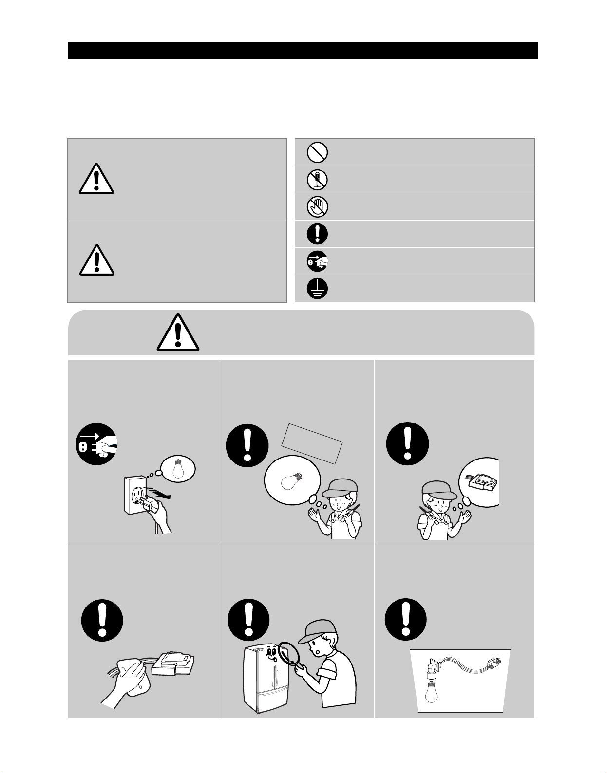
CAUTION/WARNING SYMBOLS DISPLAYED
Indicates that a
Warning
danger of death
or serious injury
exists.
Indicates that a risk
Caution
of personal injury
or material damage
exists.
Warning & Caution
Pull the power plug out to
exchange the interior lamp
of the refrigerator.
●
It may cause electric shock.
Use the rated components
on the replacement.
●
Check the correct model, rated
voltage, rated current, operating
temperature and so on.
SYMBOLS
means “Prohibited”.
means “Do not disassemble”.
means “No contact”.
means ”Warning or Caution”.
means “Unplug the unit before
preforming service”
means “Earth or Ground”.
On repair, make sure that the
wires such as harness are
bundled tightly.
●
Bundle tightly wires in order not to be
detached by the external force and then not
to be wetted.
Unplug
On repair, remove completely dust
or other things of housing parts,
harness parts, and check parts.
●
Cleaning may prevent the possible fire by
tracking or short.
Rated
components
After repair, check the
assembled state of components.
●
It must be in the same assembled state
when compared with the state before
disassembly.
Check if there is any trace
indicating the permeation
of water.
●
If there is that kind of trace, change
the related components or do the
necessary treatment
such as taping
using the
insulating tape.
5
Page 7
PRECAUTIONS(SAFETY WARNINGS)
❈
Please let users know following warnings & cautions in detail.
Warning & Caution
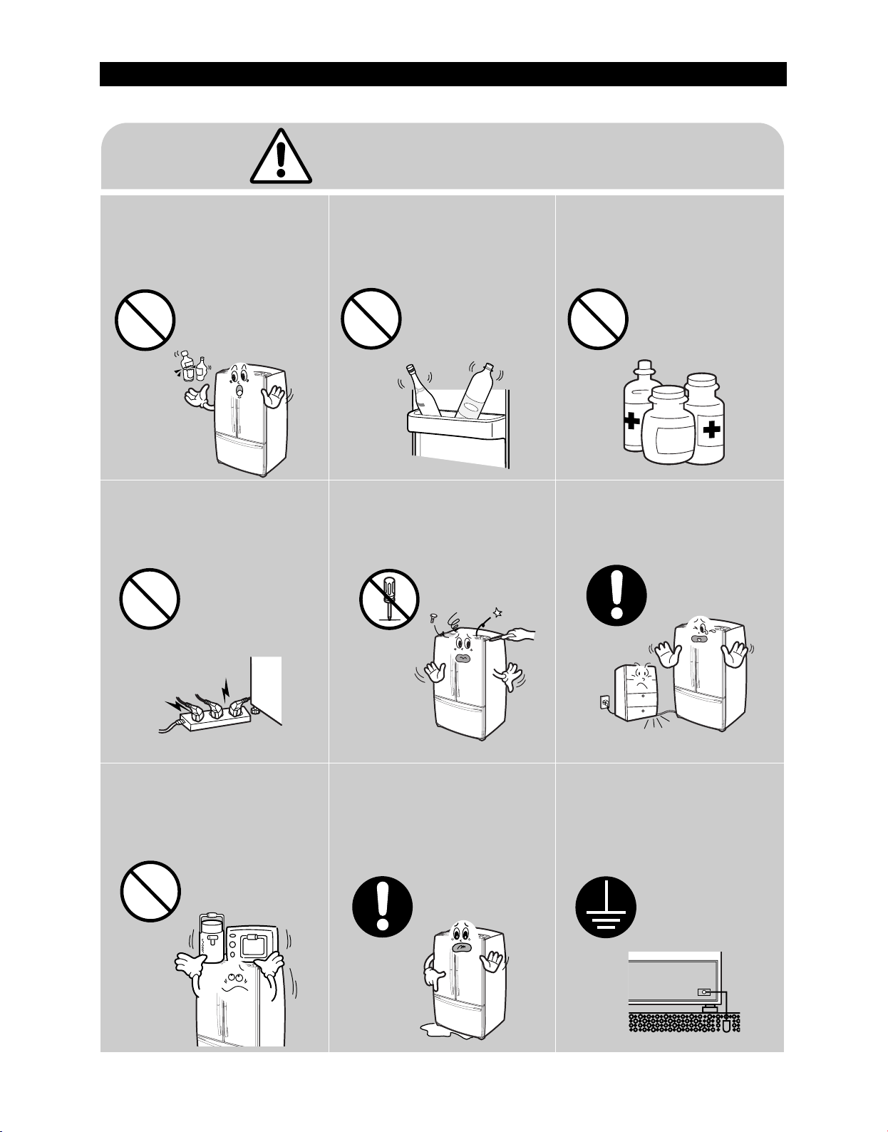
Do not allow users to put bottles or
kinds of glass in the freezer.
●
Freezing of the contents may inflict a wound.
Do not allow users to insert the
power plugs for many products
at the same time.
●
May cause abnormal generation of
heat or fire.
Do not allow users to store narrow
and lengthy bottles or foods in a
small multi-purpose room.
●
It may hurt you when refrigerator door is
opened and closed resulting in falling stuff
down.
Do not allow users to
disassemble, repair or alter.
●
It may cause fire or abnormal
operation which leads to injury.
Do not allow users to store
pharmaceutical products, scientific
materials, etc., in the refrigerator.
●
The products which temperature control
should not be stored in the refrigerator.
Do not allow users to bend the
power cord with excessive force
or do not have the power cord
pressed by heavy article.
●
May cause fire.
Prohibition
Do not allow users to store
articles on the product.
●
Opening or closing the door may cause
things to fall down, which may cause
injury.
Prohibition
Do not
disassemble
Do not allow users to install the
refrigerator in the wet place or
the place where water splashes.
●
Deterioration of insulation of electric
parts may cause electric shock or fire.
Make sure of the earth.
●
Be sure the product is properly grounded.
Earth
6
Page 8

2. PRODUCT SPECIFICATIONS
2-1) INTRODUCTION OF MAIN FUNCTION ·······································8
2-2) SPECIFICATIONS ···················································10
2-3) INTERIOR VIEWS ···················································11
2-4) MODEL SPECIFICATION ···············································12
2-5) MODEL SPECIFICATION &SPECIFICATION CHART ·····························13
2-6)DIMENSIONS OF REFRIGERATOR (INCHES) ··································16
2-7) OPTIONAL MATERIAL SPECIFICATION ·····································17
2-8) REFRIGERANT ROUTE IN REFRIGERATION CYCLE ····························18
2-9) COOLING AIR CIRCULATION ············································19
7
Page 9
2. PRODUCT SPECIFICATIONS
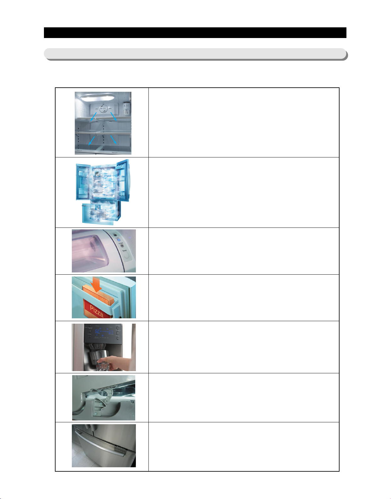
2-1) Introduction of main function
●●
A newly Developed SAMSUNG bottom mount freezer in 2008 has the following
characteristics.
Surround Multi Flow
●●
Uniform cooling for each shelf and even in corner in fresh
food compartment by centerpositioned fan and duct with
multiple flow effluences
Twin Cooling System
●●
The refrigerator and the freezer have two evaporators.
Given this independent system, the freezer and the
refrigerator are cooled individually as required and are,
therefore, more efficient.
Food odor from the refrigerator does not affect food in the
freezer due to separate air flow circulation.
Electronic control from outside of Pantry Cover
●●
Adjustable temperature control ((around 41℉(5℃) : Deli /
around 38℉(3℃) : Fresh / around 34℉(1℃) Chilled )
Temperature control from outside of the Pantry : user
friendly design helps keep foods fresh for longer
16" Pizza Corner
●●
Can be used for 16" pizza if stand flip tilting pocket.
Ice and Water Dispenser
●●
The ice and water dispenser provides ice and cold water at
any time.
Secure Auto Close Door System
●●
Secure Auto Close Door System
●●
Cool tight doors
●●
Energy saving
●●
Preventing sweat on fridge doors
Easy Handle System
●●
Ez-open Freezer Door
●●
Ergonomic Door Design
8
Page 10
2. PRODUCT SPECIFICATIONS
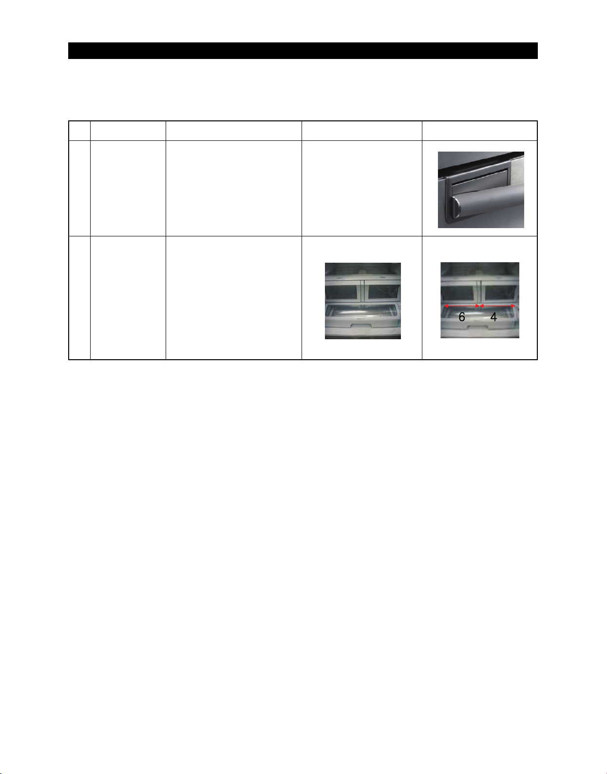
▶ Changing Items
NO Item Details
The freezer door is much
1
2
Easy
Handle
drawer
user-friendly.
So, it comes as much
convenient.
Pantry is deleted. And,
the dimension of the
right-side drawer is 6:4
(H x W) with the
shelf being raised. So,
the right-side drawer can
be pulled out with the left
door closed.
New ModelBasic Model
9
Page 11
PRODUCT SPECIFICATIONS
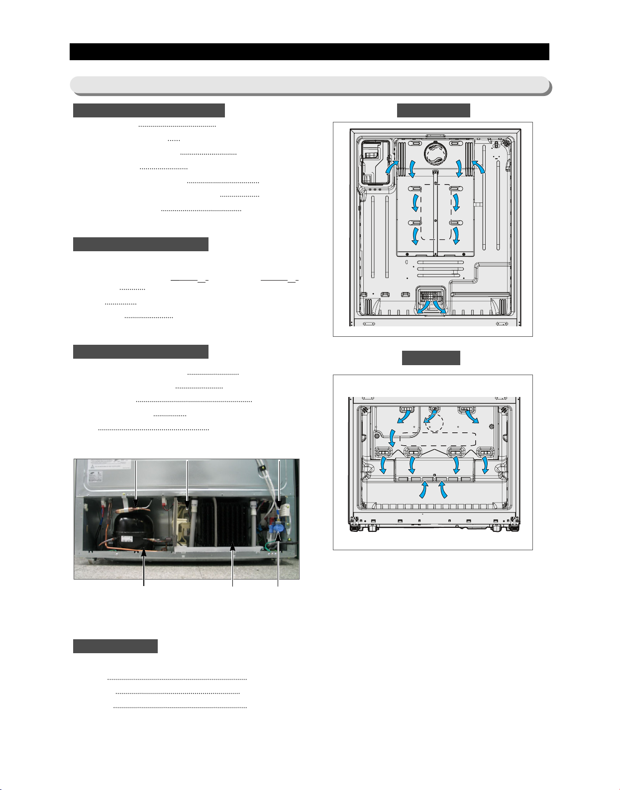
Fan
Fan
(Air inlet)
(Air inlet)
Heat exchanger
Fan
Fan
(Air inlet)(Air inlet)
Heat exchanger
FanFanFan
(Air inlet)(Air inlet)(Air inlet)
Heat exchanger
2-2) Specifications
ELECTRICAL SPECIFICATIONS
Defrost Control From 24 to 32 hrs
Thermo Bimetal Protector 140°F(60℃)(off) 104°F(40℃)(on)
Defrost Thermistor(502AT) 50°F(10℃)(off)
Electrical Rating AC115V 60Hz 11.6 Amps
Maximum Current Leakage 0.25 mA
(Air inlet)
Maximum Ground Path Resistance 0.1 Ohm
Energy Consumption 570KWh/year
NO LOAD PERFORMANCE
Ambient Temperature 70
℉(21℃) 90℉(32℃)
Refrigerator,℉ 34℉(1℃)∼46℉(8℃) 34℉(1℃)∼46℉(8℃)
Freezer,℉ -14℉(-26℃)∼8℉(-13℃) -14℉(-26℃)∼8℉(-13℃)
Run Time,% 40 60
REFRIGERATION SYSTEM
Refrigerant Charge (R134a) 5.64 oz(160g)
Compressor((MK172D-R2U) 897 Btu/hr(0.263kw)
Compressor oil Freol α-10
""
Capillary tube(Dia, Length) 0.032
""((00..8811mmmm,,22999977mmmm))
,118
Dryer Molecular Sieve XH-9
Refrigerator
Fan
Fan
Heat exchanger
Heat exchanger
Freezer
(Air inlet)(Air inlet)
(Air inlet)
Fan
Fan
C-Fan Noise FilterDryer
Compressor
INSTALLATION
Clearance must be provided for air circulation
AT TOP 1
AT SIDES 0.5
AT REAR 1
condenser Water Valve
"" ((2255mmmm))
"" ((1155mmmm))
"" ((2255mmmm))
10
Page 12
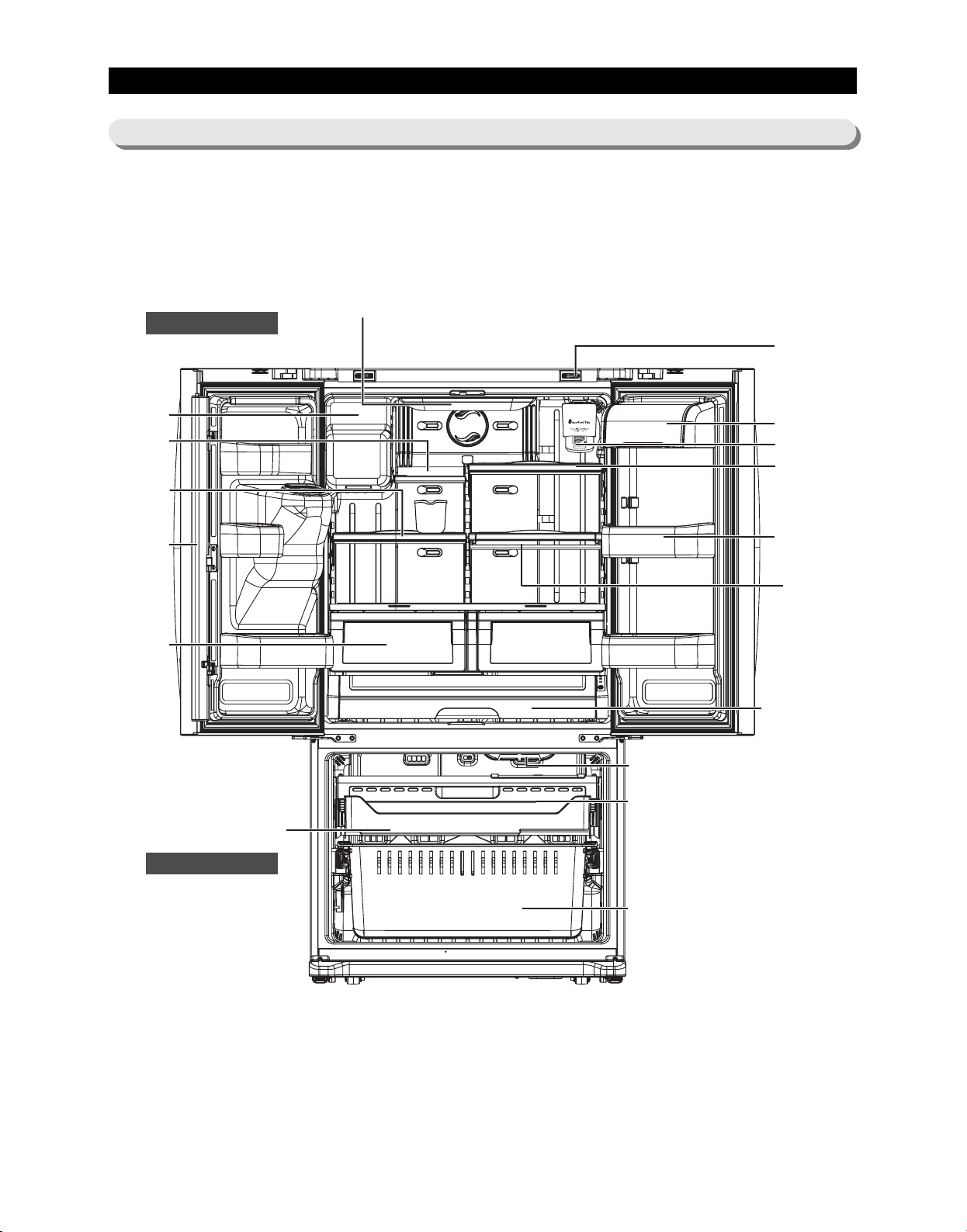
PRODUCT SPECIFICATIONS
Auto Door Closer
Water Filter
Dairy Compartment
Door Bins
Cool Select Pantry
TM
Light
Vertical Hinged
Section
Vegetable & Fruit
Drawers
Tilting Pocket
Light
Pull Out Drawer
Freezer Drawer Bin
Slide-Shelf
Quick-Space
Glass Shelf
Ice-Maker
Foldable-Shelf
Slide-Shelf
2-3)
Interior Views
Refrigerator
Freezer
11
Page 13
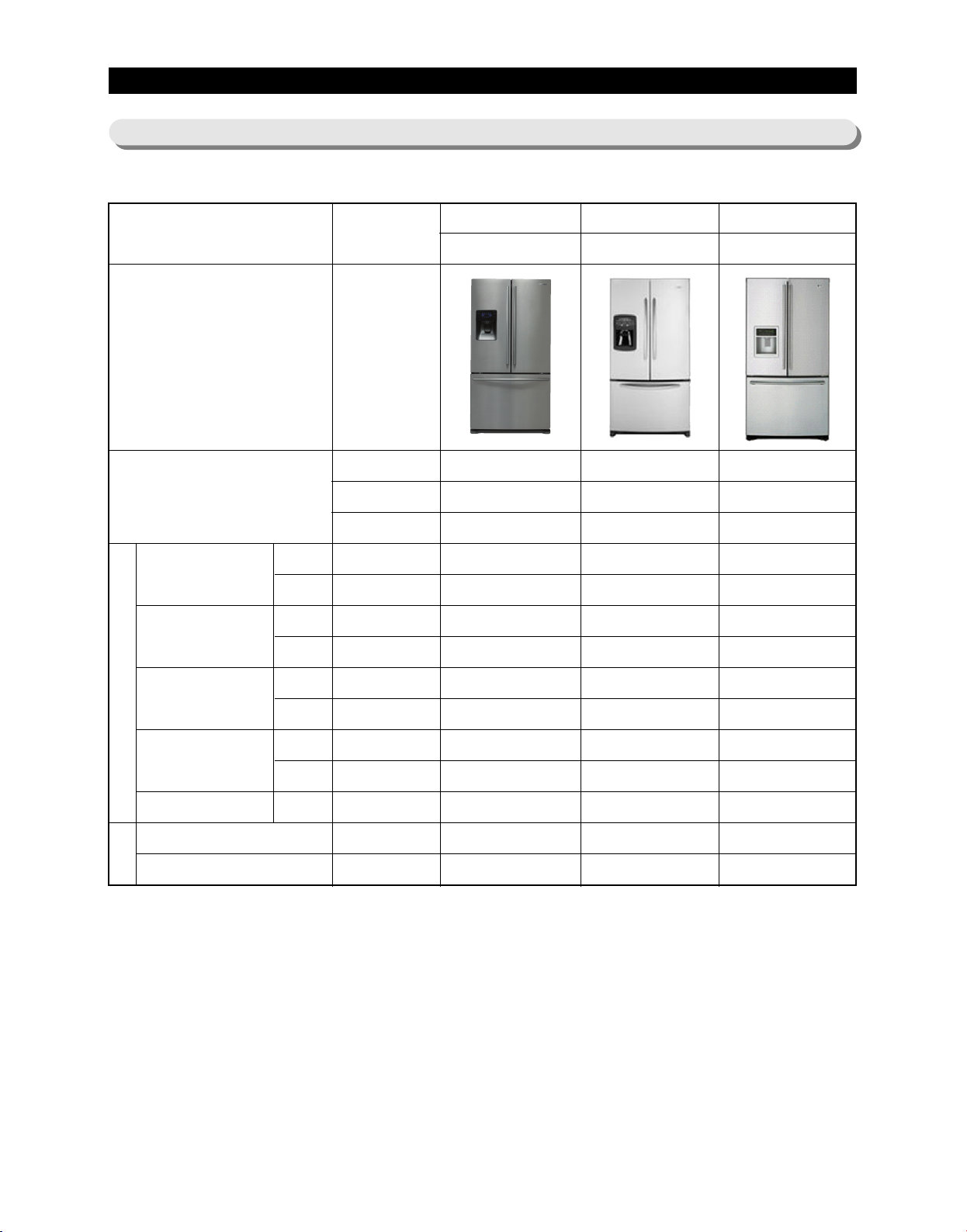
PRODUCT SPECIFICATIONS
2-4) Model Specification
ITEM SPEC
Appearance
Product Zone
Cooling
Speed(Min)
89.6℉(32°C)
F-Room
R-Room
F-Room
R-Room
Cooling Tech
Door Shape
Special Room
250↓
250↓
-26.0↓
2.0↓
SAMSUNG
RF267AB
Twin Cooling
Contour
Cool Select Pantry
209.8
201.8
-28.7
1.0
MAYTAG
MFI2568AES
Mono Cooling
Contour
Pantry
246
575
-27.2
1.6
LG
LFX25960ST
Mono Cooling
Contour
Pantry
224
232
-28.8
-1.8
109.4℉(43°C)
Performance
Temperature
Distribution
(Fridge)
Operation rate
Sound power level
Sound Pressure level
Noise
F-Room
R-Room
F-Room
R-Room
N-N
-18.0↓
5.0↓
2.0↓
2.0↓
60%↓
46dB↓
45dB↓
-21.9
1.1
0.1
0.2
54.0
42.9
41.2
-20.9
5.9
0.6
1.1
60.7
47.0
48.2
-22.5
0.8
1.3
0.5
56.5
41.7
40.1
12
Page 14
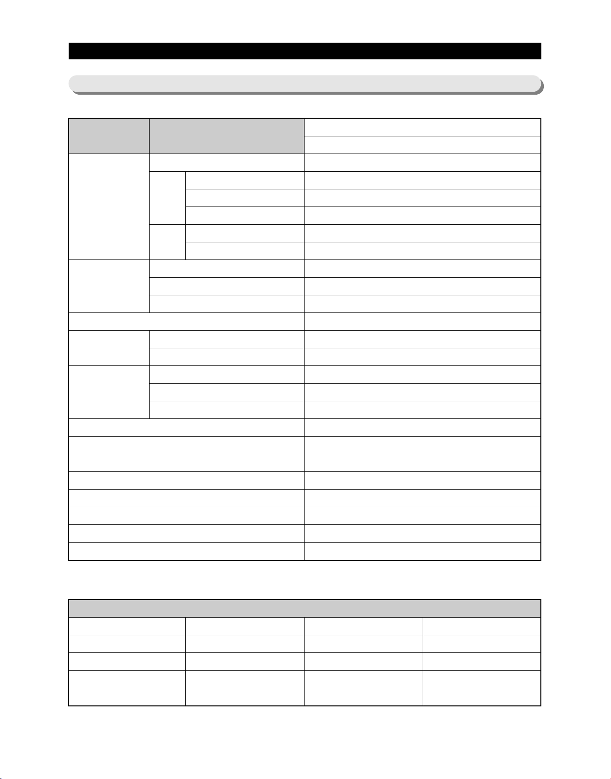
PRODUCT SPECIFICATIONS
2-5) Model Specification &Specification Chart
ModelITEM
W
On Cabinet
External size
D
H
Net
Capacity
Efficiency of volume
Weight
Packing
Compressor
Rated Frequency and Frequency
Refrigerant
Foaming agent
Refrigerant Input Amount
Kind of Refrigerator
Motor Rated Consumption Power
Electric Heater Rated Consumption Power
W/O Handle
With Handle
W/O Hinge Cap
With Hinge Cap
Total
Freezer
Refrigerator
Set
Packing
Width
Depth
Height
RF267AB
Ice & Water Dispenser with Pantry
35.7 inch (908mm)
29.1 inch (740mm)
32.9 inch (836mm)
35.6 inch (905mm)
68.6 inch (1744mm)
69.8 Inch (1778mm)
25.9(733.4)→25.8(730.6)
8.2 Cu.ft(232.2ℓ)
17.7 Cu.ft(501.2ℓ)
50.17%
330 Pounds (150kg)
363 Pounds (165kg)
38.6 Inch (980mm)
39.4 Inch (1001mm)
75.7 Inch (1923mm)
reciprocate
AC 115V/60Hz
R 134a
C-Pantane
5.64 oz (160g)
Indirect Cooling Method Refrigerator
140A
380W
Black
Real STS
White
Platinum STS
COLOR
Cabinet (Both sides of Embo)
All Black
Noble STS
Snow White
Noble STS
Door
Empire Black
Versailles Stainless
Snow White
Stainless Platinum
13
Molding
I Black
Creamy STS
Snow White
Creamy STS
Page 15
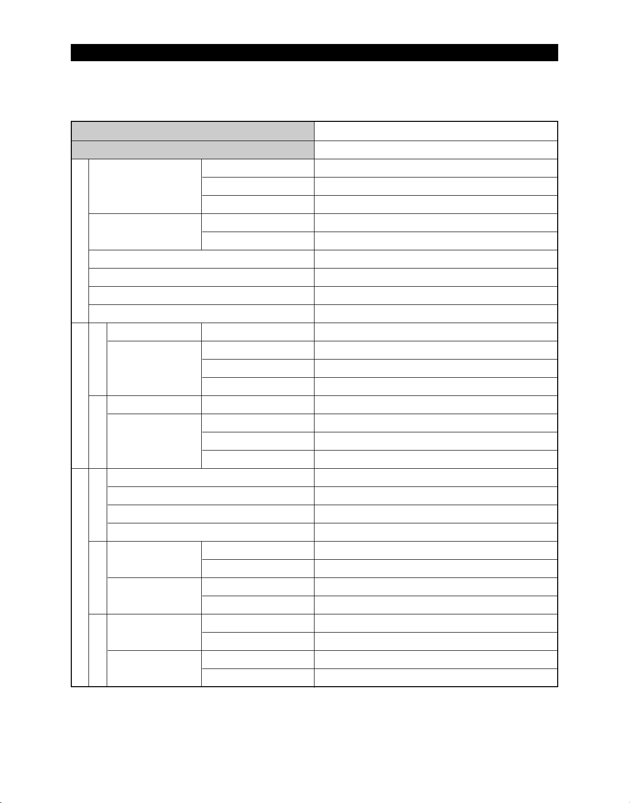
PRODUCT SPECIFICATIONS
Items
Model
Compressor
Evaporator
Condenser
Dryer
Components for FreezerDefrost Related Components
FreezerRefrigeratorDefrost Cycle
Capillary tube(Dia x Length)
Refrigerant
Model
THERMISTOR
(F-SENSOR)
502AT
Model
THERMISTOR
Model
Starting type
Oil Charge
Freezer
Refrigerator
Temperature Selection
-14℉(-26℃)
-2℉(-19℃)
8℉(-13℃)
Temperature Selection
34℉(1℃)
Specification
RF267AB
MK172D-R2U
R.S.C.R
FREOL α- 10
SPLIT FIN TYPE
SPLIT FIN TYPE
Forced and natural convection type
Molecular sieve XH-9
0.032” x 118” (0.81mm x 2997mm)
R134a
ON(℉)
-11℉(24℃)
1℉(-17℃)
11℉(-12℃)
ON(℉)
36℉(2℃)
OFF(℉)
-17℉(-27℃)
-5℉(-21℃)
5℉(-15℃)
OFF(℉)
32℉(0℃)
(R-SENSOR)
Room Temperature Sensor Components
Defrost SensorBimetal
502AT
First Defrost Cycle (Concurrent defrost of F and R)
Defrost Cycle(FRE)
Defrost Cycle(REF)
Pause time
F Defrost-Sensor
R Defrost-Sensor
F Bimetal-thermo
Protector
R Bimetal-thermo
Protector
38℉(3℃)
46℉(8℃)
Model
SPEC
Model
SPEC
Rated
Operating temperature
Rated
Operating temperature
40℉(4℃)
48℉(9℃)
6hr ±10min
12~23hr(vary according to the conditions used)
6~11hr(vary according to the conditions used)
12 ±1min
THERMISTOR (502AT)
5.0 ㏀ at 77℉(25℃)
THERMISTOR (502AT)
5.0 ㏀ at 77℉(25℃)
AC 125V 10A
Off : 140℉(60℃) / On : 104℉(40℃)
AC 125V 10A
Off : 140℉(60℃) / On : 104℉(40℃)
36℉(2℃)
44℉(7℃)
14
Page 16
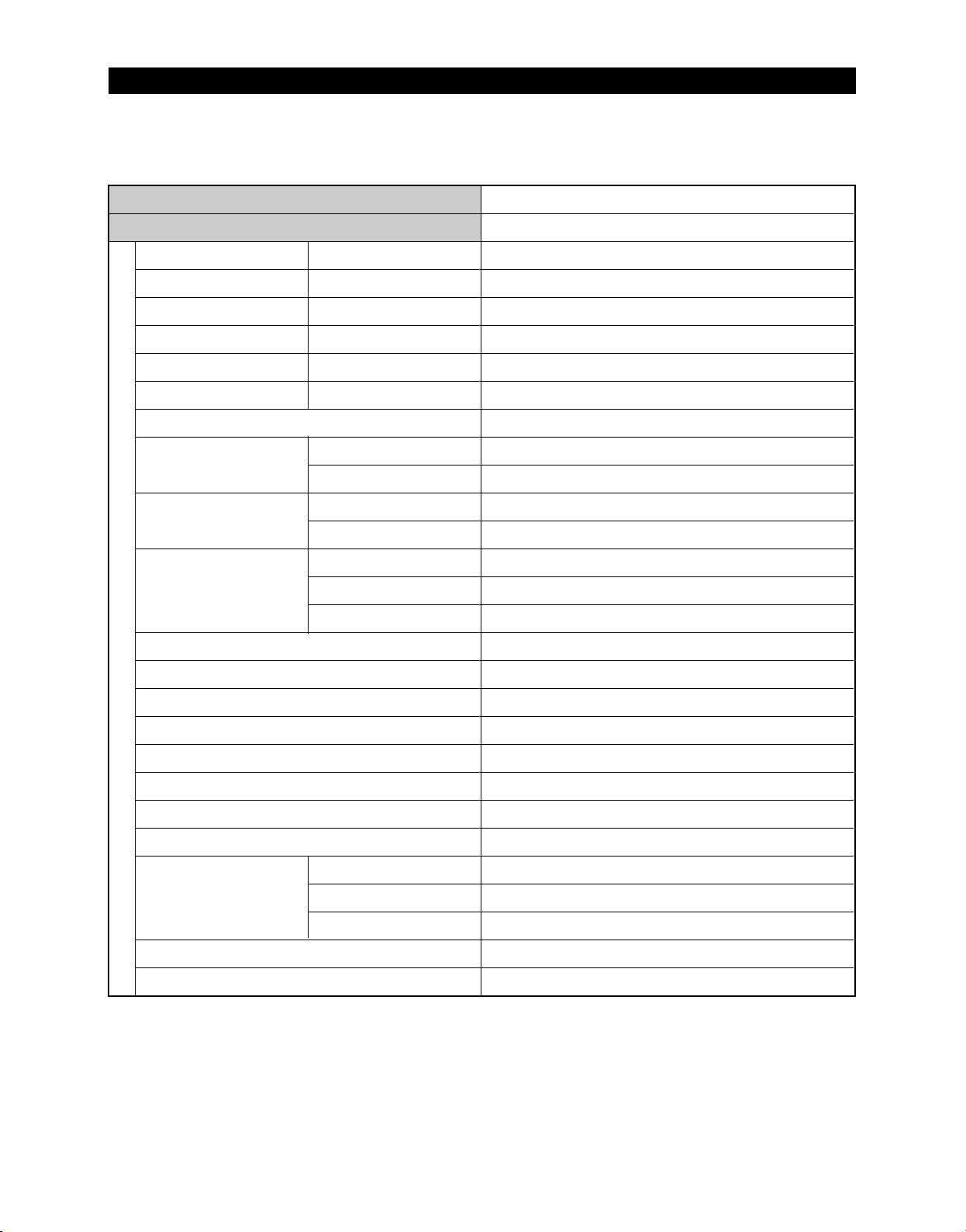
PRODUCT SPECIFICATIONS
Items
Model
Defrost Heater(FRE)
Defrost Heater(REF)
DISPENSER Heater
FRENCH Heater
ICE Duct Heater
Water Tank Heater
Bimetal thermo For Preventing Overheating of Refrigerator Lamp
Condenser for COMP
(Package type)
Starting-Relay
Over load Relay
Rated Voltage
Conducting af F Defrost
Conducting at R Defrost
Interlock with French Heater
-
Interlock with Defrost Heater (FRE)
-
AC125V 10A / 140℉(60℃) / On : 104℉(40℃)
Running
Starting
Model
Operation
Model
Temp.ON
Temp.OFF
Specification
RF267AB
AC 115V, 240W
AC115V, 120W
AC115V, 2W
AC115V, 8W
AC115V, 4W
DC 12V, 2W
12㎌ ,250V
-
PTHTM100MD3-00
10 Ω± 20%
4TM435RFBYY-53
266± 41℉(130± 5℃)
141.8± 48.2℉(61± 9℃)
AC 115V/ 60Hz
Electric Components
Door Switch
MOTOR-BLDC(FRE)
MOTOR BLDC(ICE ROOM)
MOTOR-BLDC(REF)
MOTOR-BLDC(CIRCUIT)
MOTOR-DAMPER(PANTRY)
Lamp(FRE)
Lamp(REF)
REF(ICE ROOM)
Power cord
Earth Screw
FRE
REF
DC12V / FDQT06SS3
DC12V / DREP5020LB
DC12V / FDQT06SS3
DC12V / FDQT04SS2
DC12V / NSBY001TA1
AC 120V / 60W(1EA)
AC 120V / 60W(2EA)
AC 125V 1.5A (1EA)
DC200V 1.5A / MS-406-SS-01(2EA)
125~250V /11A, EMB606
AC125V 15A
BSBN (BRASS SCREW)
15
Page 17
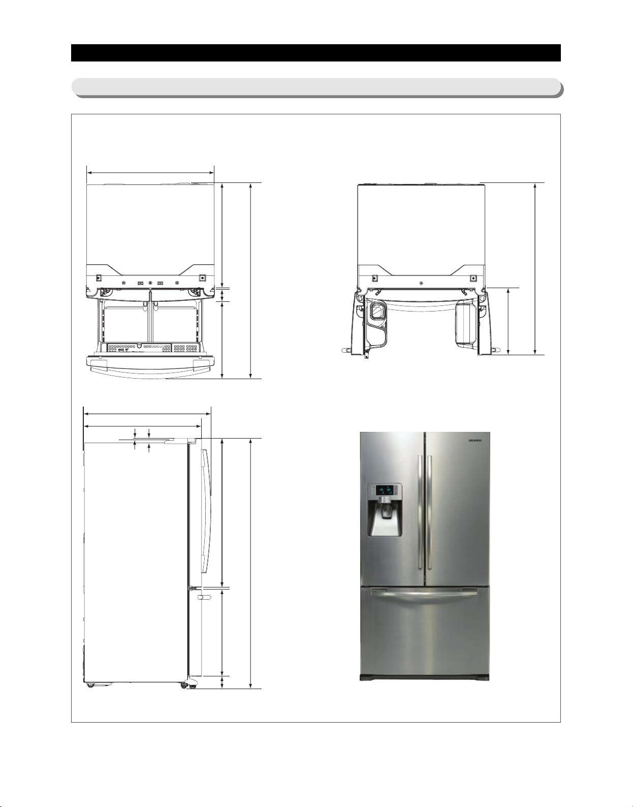
PRODUCT SPECIFICATIONS
29.1"(739mm)
3.4"(86mm)
21.6"(549mm)41.7"(1059mm)
0.6"(15mm)
69.8"(1778mm)
1.3"(34mm)
0.2"(5mm)
32.9"(836mm)
35.6"(905mm)
35.7"(908mm)
24.3"(617mm)
3.4"(86mm)
54.5"(1384mm)
18.7"(475mm)
47.8"(1214mm)
2-6)Dimensions of Refrigerator (Inches)
16
Page 18
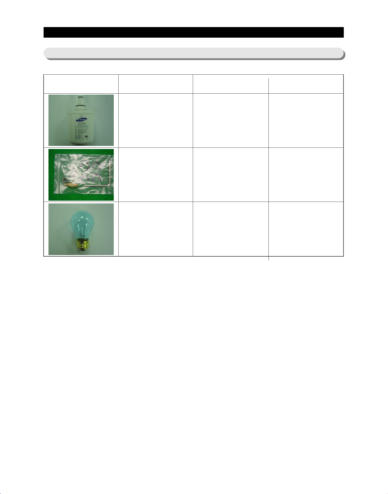
PRODUCT SPECIFICATIONS
2-7) Optional Material Specification
Part Name
FILTER
WATER-ASSY
ASSY-PACKING
SUB
LAMP INCANDENT
Part Code
DA29-00003B
DA99-00240S
4713-001223
AMOUNT
1
1
3
17
Page 19
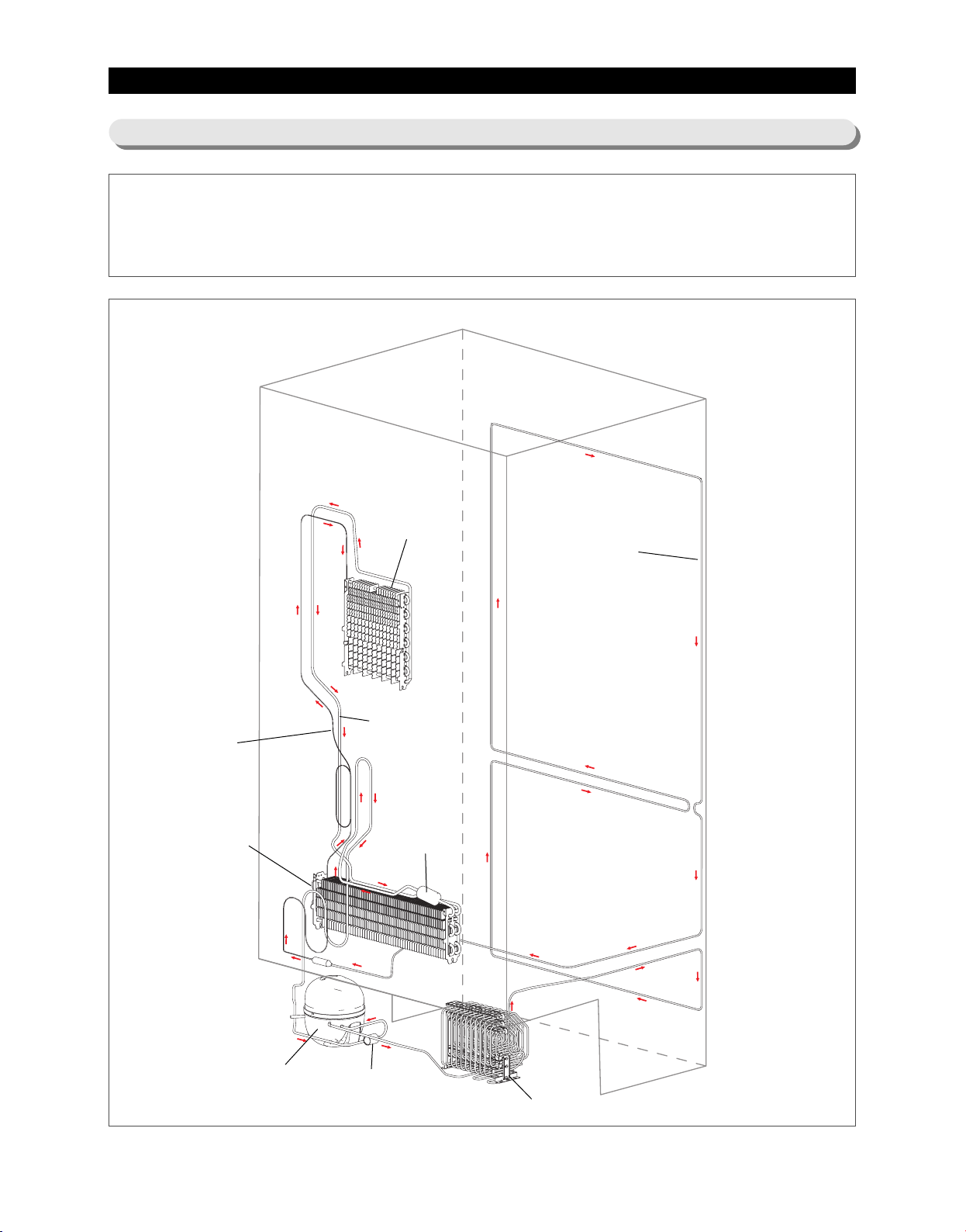
PRODUCT SPECIFICATIONS
2-8) Refrigerant Route in Refrigeration cycle
Compressor → condenser → Hot Pipe → Dryer → Capillary Tube → Refrigerator Evaporator → Freezer
Evaporator→ Suction Pipe → Compressor
Refrigerator
Evaporator
Hot Pipe
Capillary Tube
Freezer
Evaporator
Compressor
Suction Pipe
Accumulator
Muffler
Condenser
18
Page 20
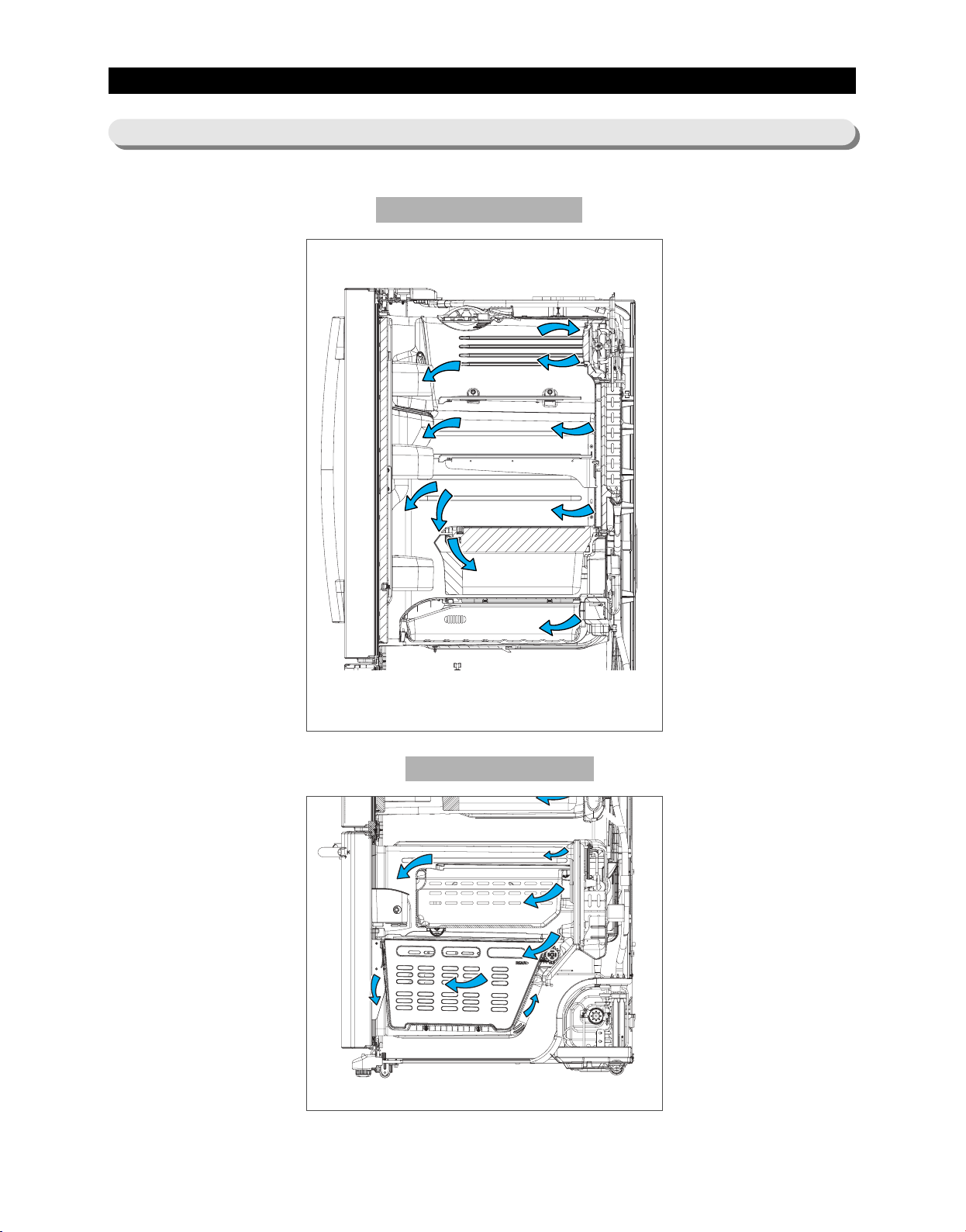
PRODUCT SPECIFICATIONS
2-9) Cooling Air Circulation
Refrigerator
Freezer
19
Page 21

3. DISASSEMBLY AND REASSEMBLY
3-1) PRECAUTION ·······································21
3-2) REFRIGERATOR DOOR
3-3) DOOR HANDLE
······································24
3-4) REFRIGERATOR LIGHT
·································22
·································25
3-5) COVER-DISPLAY & WATER-DISPENSER
3-6) WATER-DISPENSER
3-7) GLASS SHELF
·······································27
3-8) FOLDABLE GLASS SHELF
···································26
································ 28
3-9) VEGETABLE & FRUIT DRAWERS SHELF
3-10) COOL SELECT PANTRY
3-11) WATER TANK
3-12) MOTOR DAMPER
·······································30
····································· 32
3-13) WATER FILTER (DISASSEMBLY)
3-14) WATER FILTER (REASSEMBLY)
·································29
····························32
····························33
·······················25
·······················28
3-15) VERTICAL HINGED SECTION
3-16) VERTICAL HINGED SECTION
·····························33
·····························34
3-17) EVAPORATOR COVER IN REFRIGERATOR
3-18) EVAPORATOR IN REFRIGERATOR
3-19) FREEZER DOOR
3-20) PULL OUT DRAWER
3-21) ICE-MAKER
3-22) FREEZER LIGHT
3-23) DOOR SWITCH IN FREEZER
·····································37
···································38
········································39
·····································40
······························40
3-24) EVAPORATOR COVER IN FREEZER
3-25) EVAPORATOR IN FREEZER
3-26) MACHINE COMPARTMENT
3-27) ELECTRIC BOX
······································45
·······························41
·······························42
··························36
··························41
·····················35
20
Page 22
ASSEMBLY & DISASSEMBLY
3-1) PRECAUTION
• Unplug the refrigerator before cleaning and making repairs.
• Remove any foreign matter or dust from the power plug pins.
- Otherwise there is a risk of fire.
• Do not use a cord that shows cracks or abrasion damage along its length or at either end.
• Do not plug several appliances into the same multiple power board. The refrigerator should always be
plugged into its own individual electrical which has a voltage rating that matched the rating plate.
- This provides the best performance and also prevents overloading house wiring circuits, which could
cause a fire hazard from overheated wires.
• Do not install the refrigerator in a damp place or place where it may come in contact with water.
- Deteriorated insulation of electrical parts may cause an electric shock or fire.
• The refrigerator must be grounded.
- You must ground the refrigerator to prevent any power leakages or electric shocks caused by current
leakage from the refrigerator.
• Do not put bottles or glass containers in the freezer.
- When the contents freeze, the glass may break and cause personal injury.
• Do not store volatile or flammable substances in the refrigerator.
- The storage of benzene, thinner, alcohol, ether, LP gas and other such products may cause
explosions.
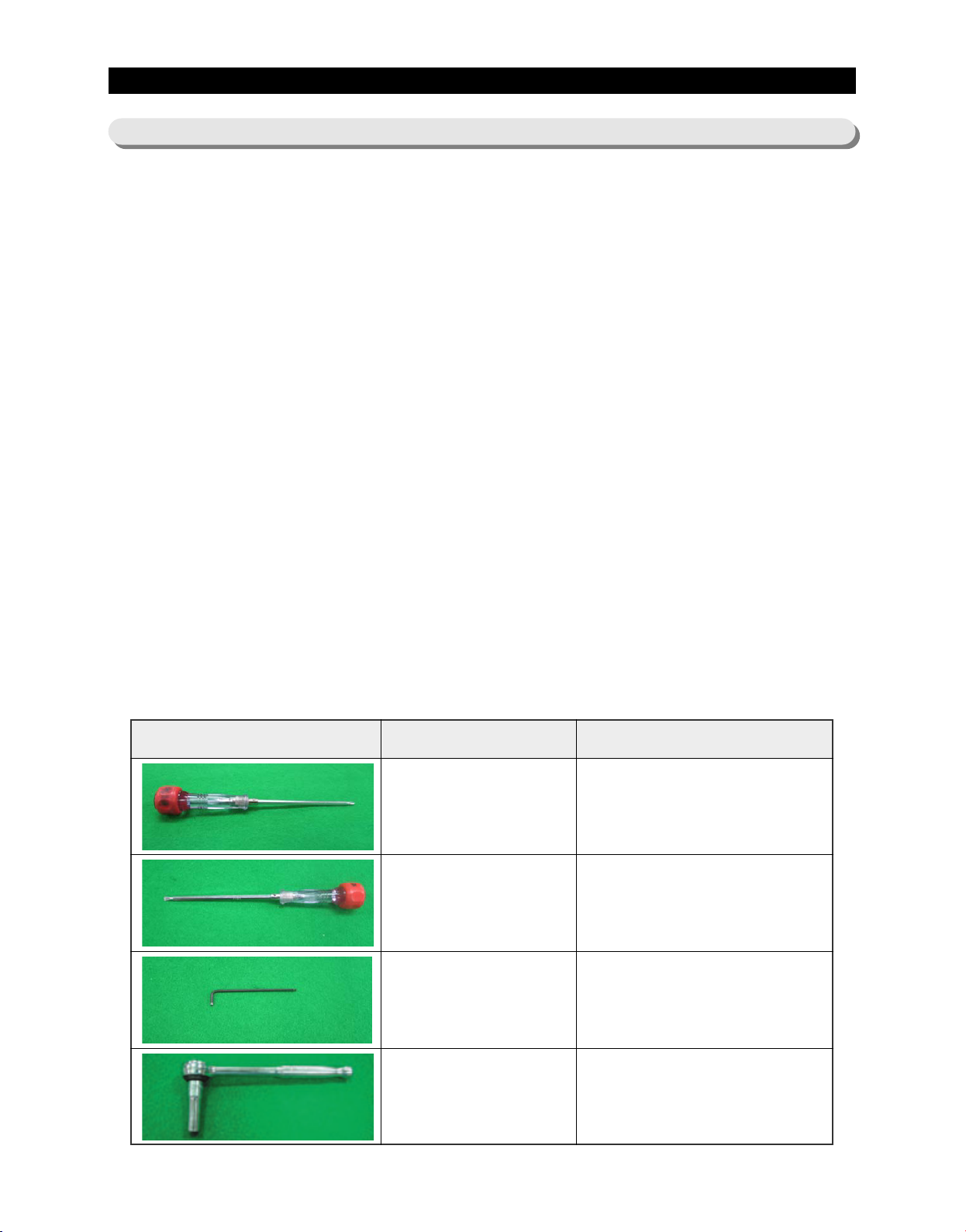
- NEED TOOL
IMAGE ITEM USE
Phillips Head Driver
Flat Head Driver
Hex Wrench Ø2mm
Socket Wrench Ø10mm
Use for assembling and
disassembling of screw
Use for assembling and disassembling
of HomeBar, Dispenser, Deli
Cartessen Box, Main PBA etc...
Use for assembling and
disassembling of Handle
Use for assembling and
disassembling of Door Hinge
21
Page 23
DISASSEMBLY AND REASSEMBLY
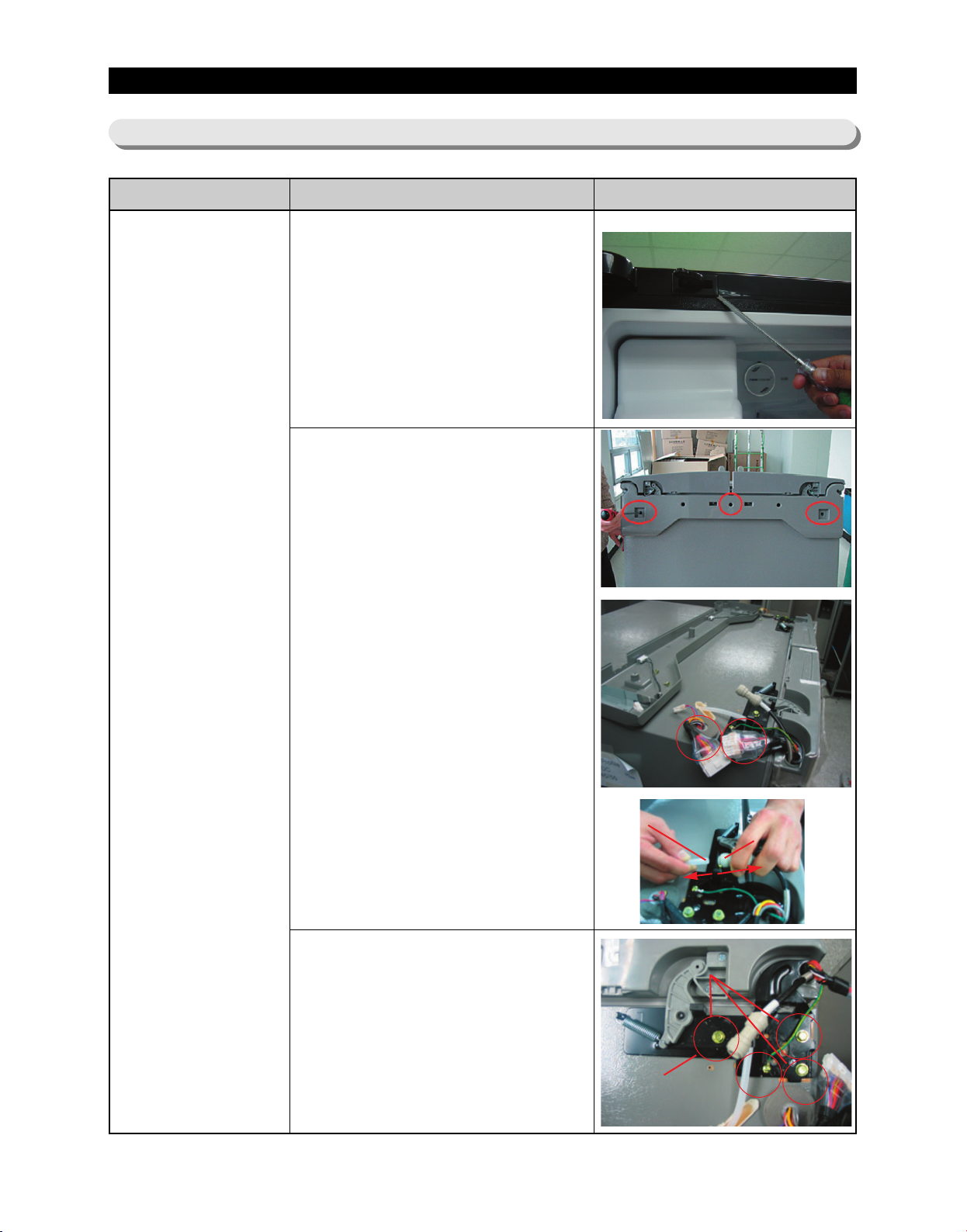
3-2) Refrigerator Door
Part Name How To Do Descriptive Picture
1. With the door opened, remove
the Top Table cap() with a Flat
head screwdriver, and close the
door.
2. Remove the 3 screw holding
down the Top Table and remove
the Top Table().
3. Disconnect the electrical
connector() above the upper
right door hinge and the 3
electrical connectors() above
the upper left door hinge.
Disconnect the water tube() by
pulling the tube fitting() apart
as shown in the picture.
Refrigerator
Door
4. Remove the 3 hex head bolts()
found attatched to the upper left
and right door hinges with a
Wrench(10mm).
With a Philips head screwdriver,
remove the ground screw() found
attatched to the upper left and right
door hinges. Remove the upper left
and right door hinges().
22
Page 24

DISASSEMBLY AND REASSEMBLY
Part Name How To Do Descriptive Picture
5. Lift the door straight up to
remove.
Refrigerator
Door
6. With a Philips head screwdriver,
remove the two screws ()
attatched to the lower left and
right door hinges.
With a Wrench(10mm), remove
the 2 Flat head screws ()
attatched to the lower left and
right door hinges.
Remove the lower left and right
door hinges ().
23
Page 25
DISASSEMBLY AND REASSEMBLY
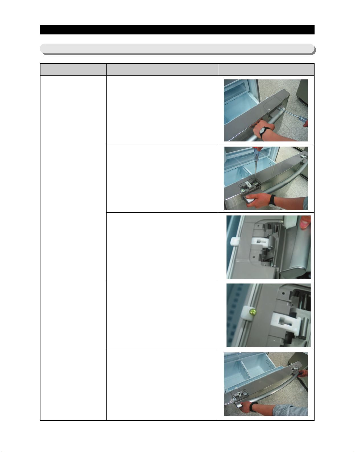
3-3) Refrigerator Door
Part Name How To Do Descriptive Picture
1. Remove the Cap Door with
using a flat-blade(-) screwdriver.
2.Unscrew 4 screws
Door Handle
Freezer
3. Lift up the handle to have the
Slider Handle Fre() pushed
back.
4. After having the Slider Handle
Fre() pushed back, screw up
at the hole.
5.Remove the door handle by
lifting it up.
24
Page 26

DISASSEMBLY AND REASSEMBLY
3-4) Refrigerator Light
Part Name How To Do Descriptive Picture
1. Remove the light cover by
pulling it down with pushing the
rear of light cover.
Refrigerator
Light
2. Remove the lamp by turning it
counterclockwise.
3-5) Cover-display & water-dispenser
Part Name How To Do Descriptive Picture
1. Insert a flat-blade screwdriver
on the slot as shown in the
picture, and unlock the tabs.
2. Remove the display cover by
Cover-display
pushing it to the right side and
pulling it up.
①
②
3. Disengage the housing connect
of display cover
25
Page 27
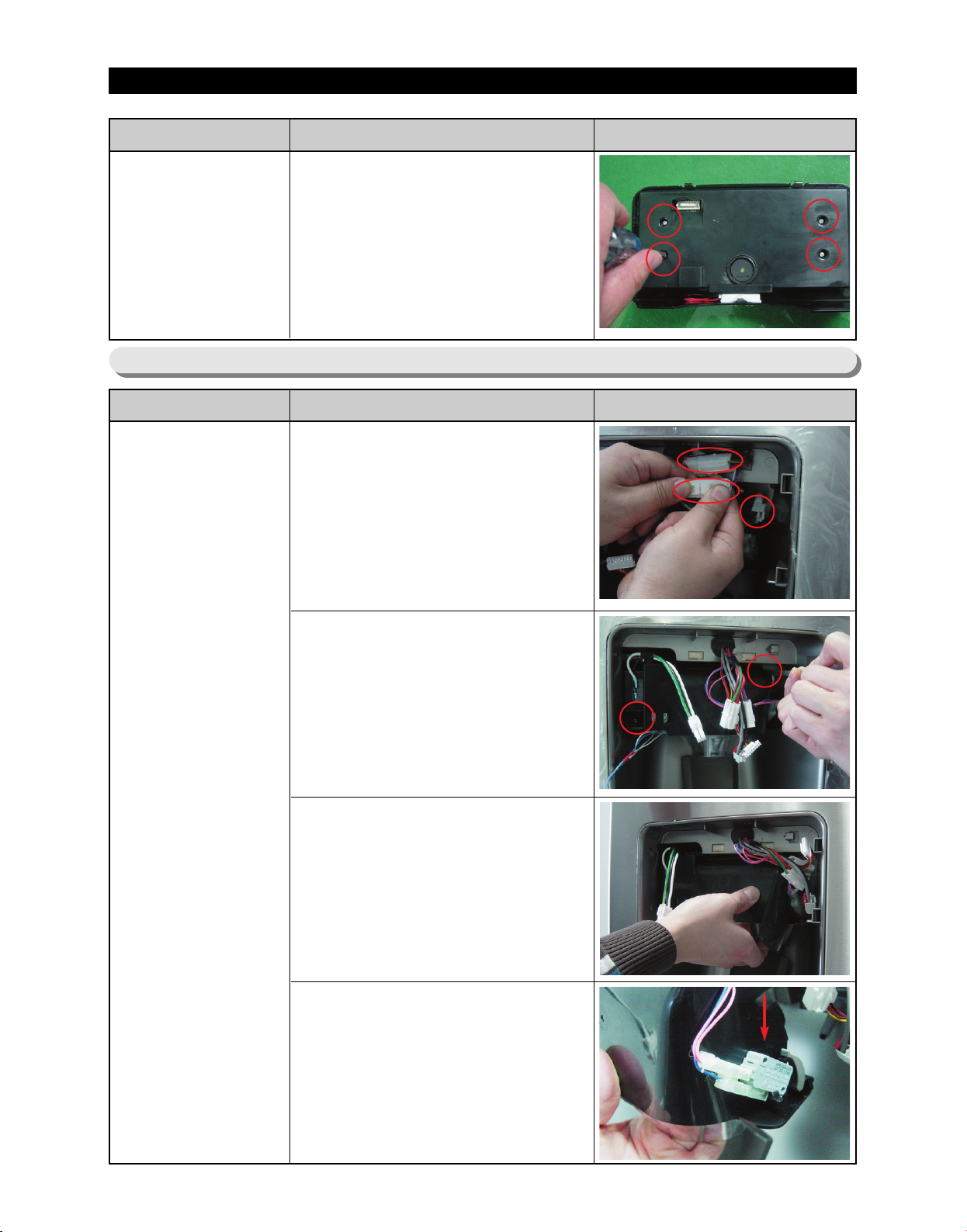
DISASSEMBLY AND REASSEMBLY
Part Name How To Do Descriptive Picture
4. Remove 4 screws of cover-
Cover-display
3-6) Water-dispenser
Part Name How To Do Descriptive Picture
display
1. Disengage the 3 Housing
Connect.
Water-dispenser
2. Remove 2 screws of the
CaseIce,Route Assy.
3. Pull the Case-Ice,Route Assy.
4. Push the hook and remove the
Micro Switch.
26
Page 28
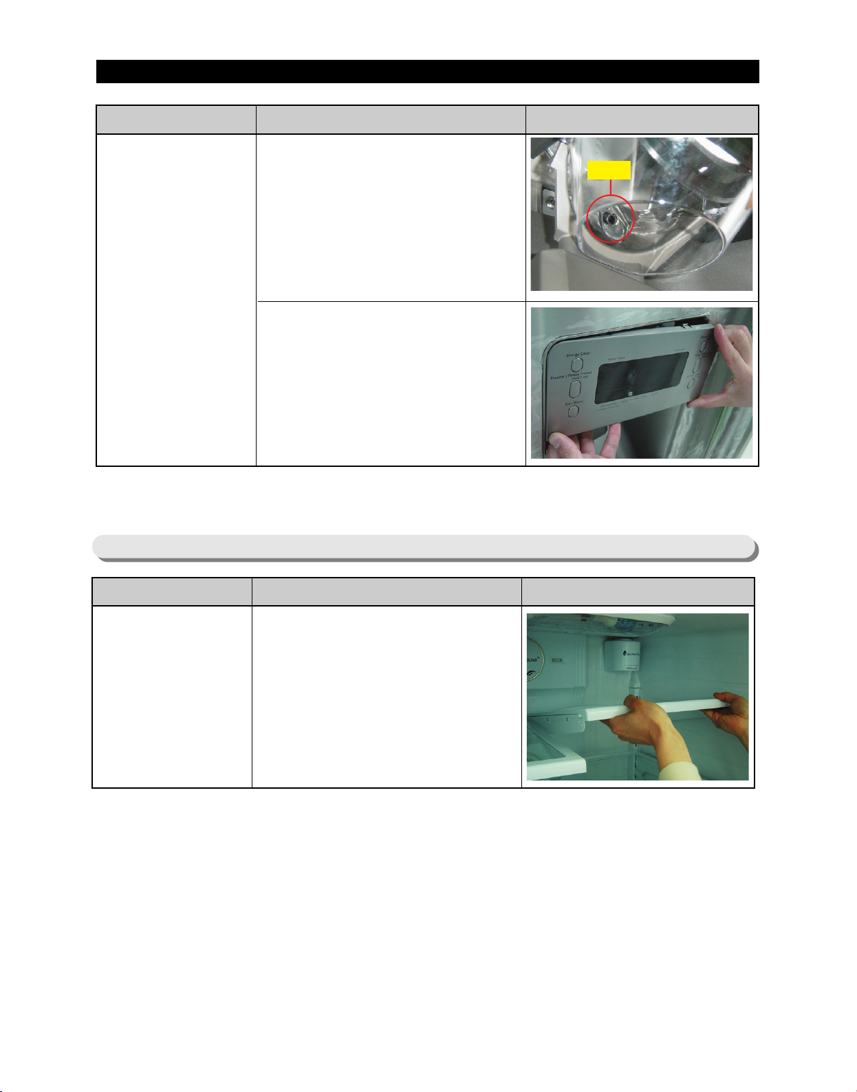
DISASSEMBLY AND REASSEMBLY
Part Name How To Do Descriptive Picture
Water-dispenser
3-7) Glass Shelf
1. Assembly shall be the contrary
order from the disassemble.
Case-Rce and Route shall be
assembled inside of hose.
Otherwise, assemble cannot be
accomplished.
2. When assembling Cover-
Display, first insert it from
leftside and then assemble to
rightside.
Otherwise, the tab can be
broken.
hose
Part Name How To Do Descriptive Picture
Remove the shelf by lifting the
Glass Shelf
front plane of the shelf up and
pulling it out.
27
Page 29
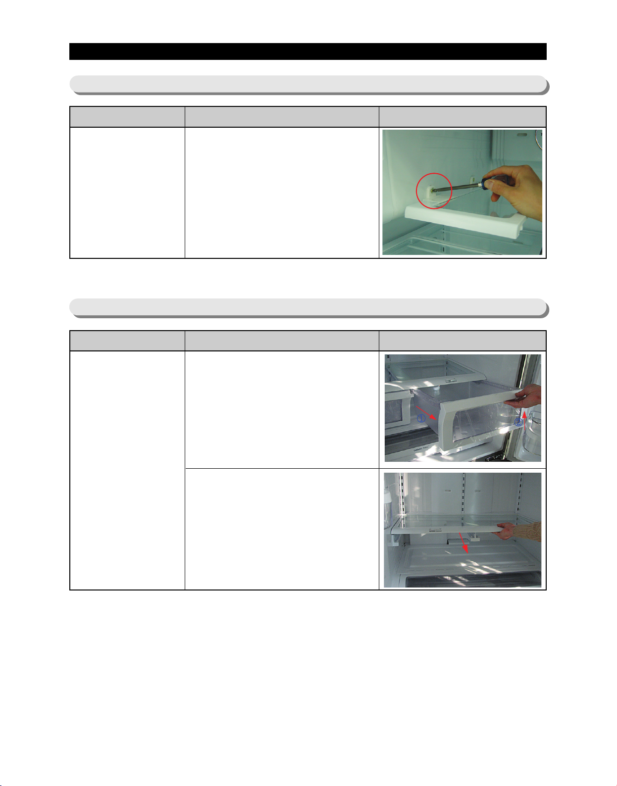
DISASSEMBLY AND REASSEMBLY
3-8) Foldable Glass Shelf
Part Name How To Do Descriptive Picture
Foldable Glass
Shelf
3-9) Vegetable & Fruit Drawers Shelf
Part Name How To Do Descriptive Picture
Vegetable & Fruit
Remove 2 screws of the Fold
Glass Shelf
1. Remove the vegetable & fruit
drawer by pulling the roller part
and lifting it up.
Drawers Shelf
2. Remove the vegetable & fruit
drawers shelf by pulling it out.
(Refer to the picture)
28
Page 30
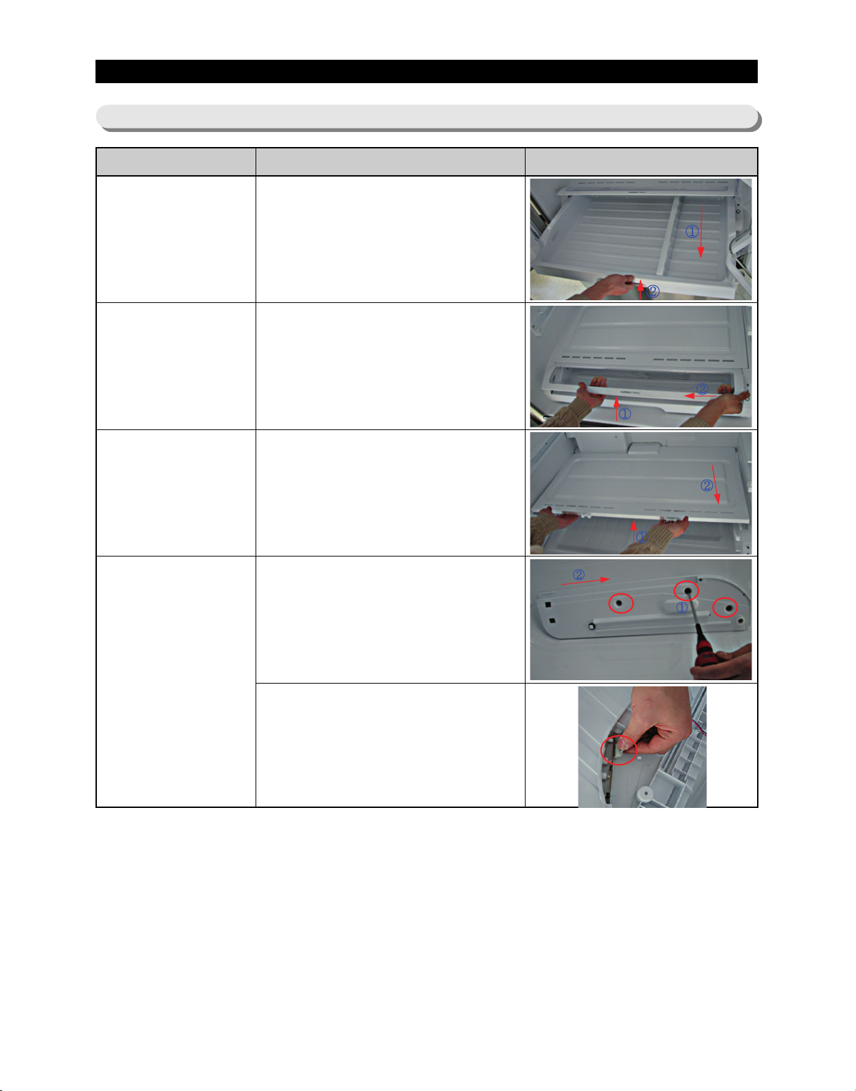
DISASSEMBLY AND REASSEMBLY
3-10) Cool Select Pantry
Part Name How To Do Descriptive Picture
1. Remove the cool select pantry
Cool Select Pantry
Cool Select Pantry
Cover
by pulling the roller part and
lifting it up.
1. Remove the cool select pantry
cover by lifting the central part
of the cover while pushing it to
the left.
Cool Select Pantry
Shelf
Cool Select Pantry
Rail
1. Remove the cool select pantry
shelf by lifting the front part of
the shelf while pulling it.
1. Remove the cool select pantry
rail by unscrewing the 3 screw
parts and pulling the rail.
2. Disconnect the housing
connector from the internal rail
part.
(Refer to the picture)
29
Page 31
DISASSEMBLY AND REASSEMBLY
3-11) Water Tank
Part Name How To Do Descriptive Picture
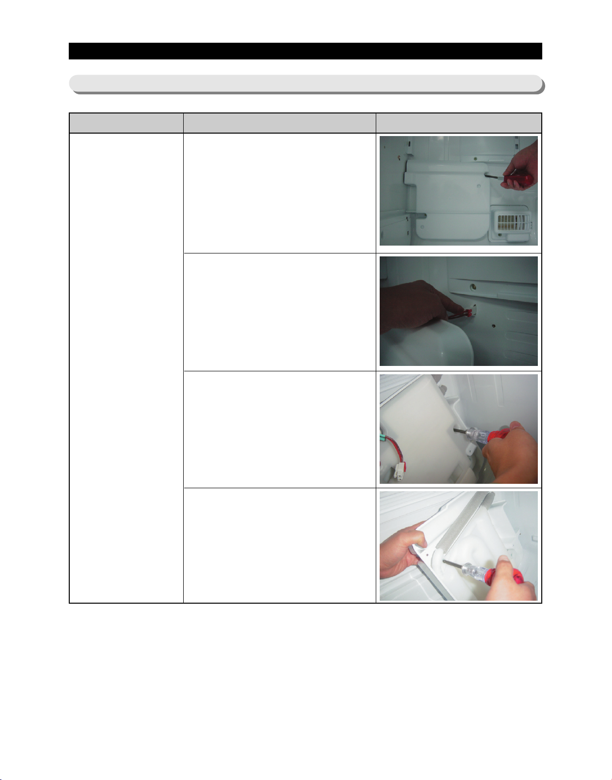
The Water Tank is located in the
lower part of the fridge. Before
disassembling the Water Tank take
out shelf and drawers and pantry
located in front of the Water Tank.
1. Remove 2 screw of the Water
Tank cover.
2. Disengage the housing
connector.
Water Tank
3. Remove the 2 screws attached
to the Water Tank heater.
Remove the Water Tank heater.
4. Remove the 2 screws attached
to the Water Tank.
Remove the Water Tank cover.
30
Page 32
DISASSEMBLY AND REASSEMBLY
Part Name How To Do Descriptive Picture
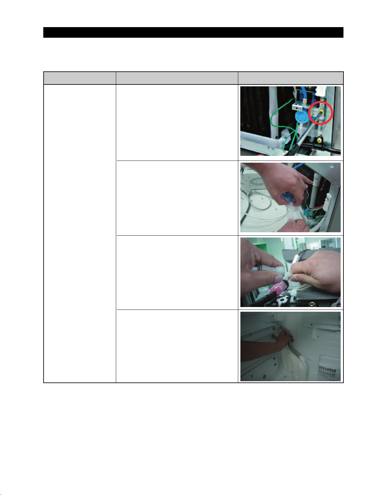
One water Tube is located in the
machine compartment of the
refrigerator. Before disassembling
the Water Tube, take out the
compressor cover.
5. Remove the water valve fixed by
the screw.
6. Disconnect the water tube by
pushing the tube fitting apart as
shown in the picture.
Water Tank
The other Water Tube is located in
the Top Table of the refrigerator.
Before disassembling the Water
Tube, take out the Top table.
7. Disconnect the Water Tube by
pushing the tube fitting apart as
shown in the picture.
8. Remove the Water Tank by
pulling the Water Tube.
31
Page 33
DISASSEMBLY AND REASSEMBLY
3-12) Motor Damper
Part Name How To Do Descriptive Picture
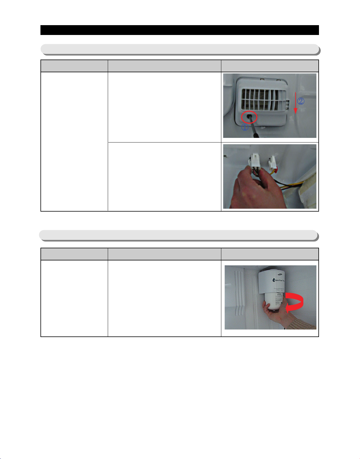
1. Remove the cool select pantry.
Remove the screw part of lower
motor damper part and then
push the motor damper down.
Motor Damper
2. Disengage 2 housing
connectors from the rear motor
damper.
(Refer to the picture)
3-13) Water Filter (Disassembly)
Part Name How To Do Descriptive Picture
1. Remove the shelf by lifting the
front plane of the shelf up and
pulling it out.
Water Filter
2. Remove the water filter by
turning it Counterclockwise.
(Refer to the picture)
32
Page 34
DISASSEMBLY AND REASSEMBLY
3-14) Water Filter (Reassembly)
Part Name How To Do Descriptive Picture
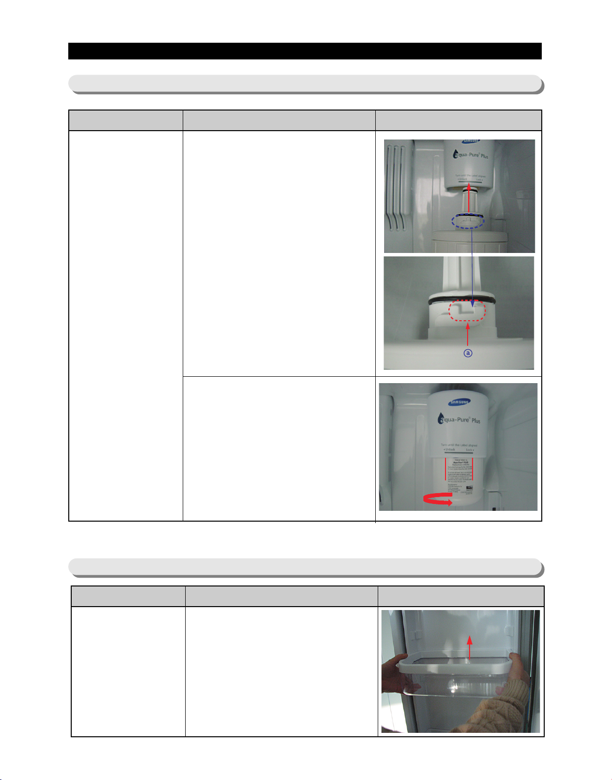
1. Place the part of (ⓐ) arrow (that
is indicating in the picture) in the
middle of the front filter cover
and push it up.
Water
Filter
2. Turn the water filter
counterclockwise until central
horizontal line of filter cover and
both ends of water filter label
are made all of the same width.
(Refer to the picture.)
3-15) Gallon Door Bin
Part Name How To Do Descriptive Picture
1. Remove the gallon door bin by
Gallon Door Bin
lifting it up.
(Refer to the picture)
33
Page 35
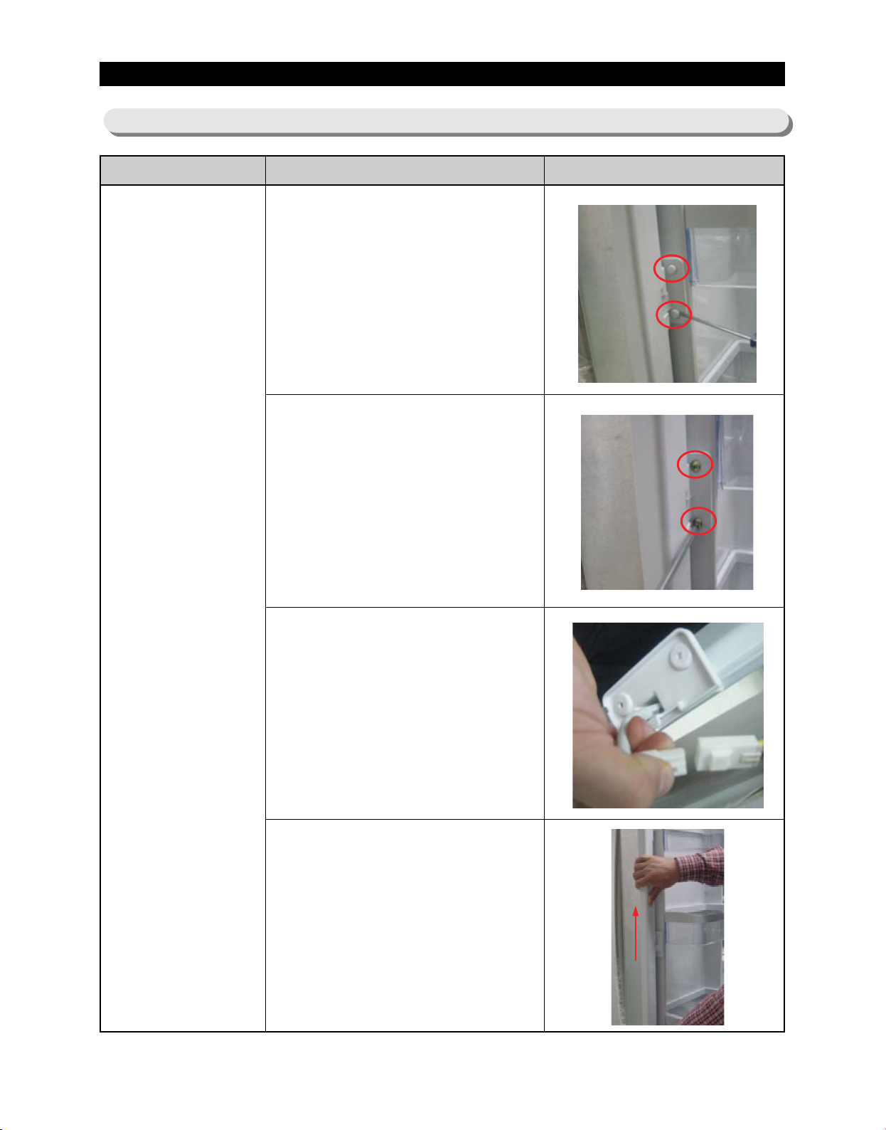
DISASSEMBLY AND REASSEMBLY
3-16) Vertical Hinged Section
Part Name How To Do Descriptive Picture
1. Remove 2 screw cap parts with
a flat-blade(-) screwdriver.
(Refer to the picture)
Vertical Hinged
Section
2. Unscrew 2 screws.
3. Disengage the internal housing
connector of the vertical hinge.
4. Remove the vertical hinged
section by lifting the vertical
hinge up.
(Refer to the picture)
34
Page 36
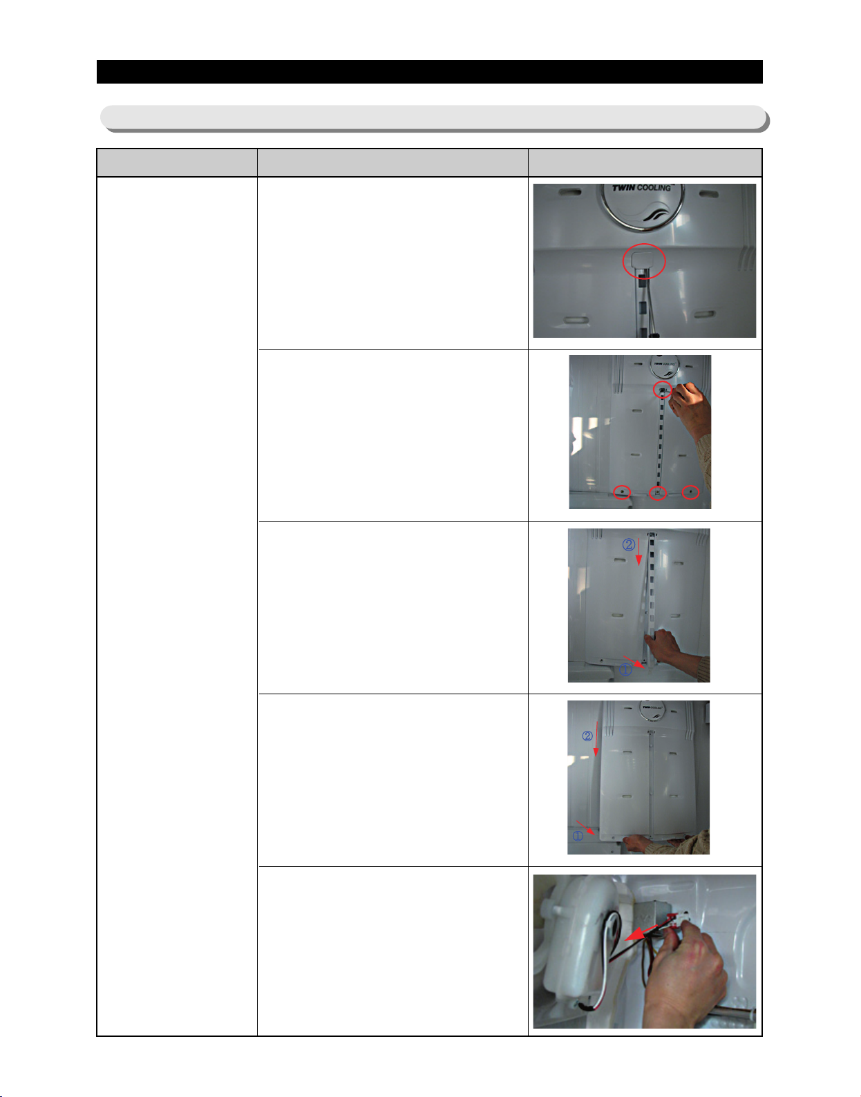
DISASSEMBLY AND REASSEMBLY
3-17) Evaporator Cover In Refrigerator
Part Name How To Do Descriptive Picture
1. Remove the angle cap with a
flat-blade screwdriver.
(Refer to the picture)
2. Unscrew 4 screws.
Evaporator Cover
In Refrigerator
3. Remove the the lower part of
angle mid by pulling it out and
pushing it down.
(Refer to the picture)
4. Remove the hook by pulling it
from the lower part and pushing
the cover down.
(Refer to the picture)
5. Disconnect the housing
connector of the rear plane.
(Refer to the picture)
35
Page 37

DISASSEMBLY AND REASSEMBLY
3-18) Evaporator In Refrigerator
Part Name How To Do Descriptive Picture
1. Remove the the housing cover
by pushing both lateral sides of
the housing cover and pulling it
out.
(Refer to the picture)
2. Disconnect the housing
connector part.
(Refer to the picture)
Evaporator
In Refrigerator
3. Unscrew 2 screws.
4. Remove the evaporator by lifting
the bottom side of it up and
pulling it out.
(Refer to the picture)
36
Page 38
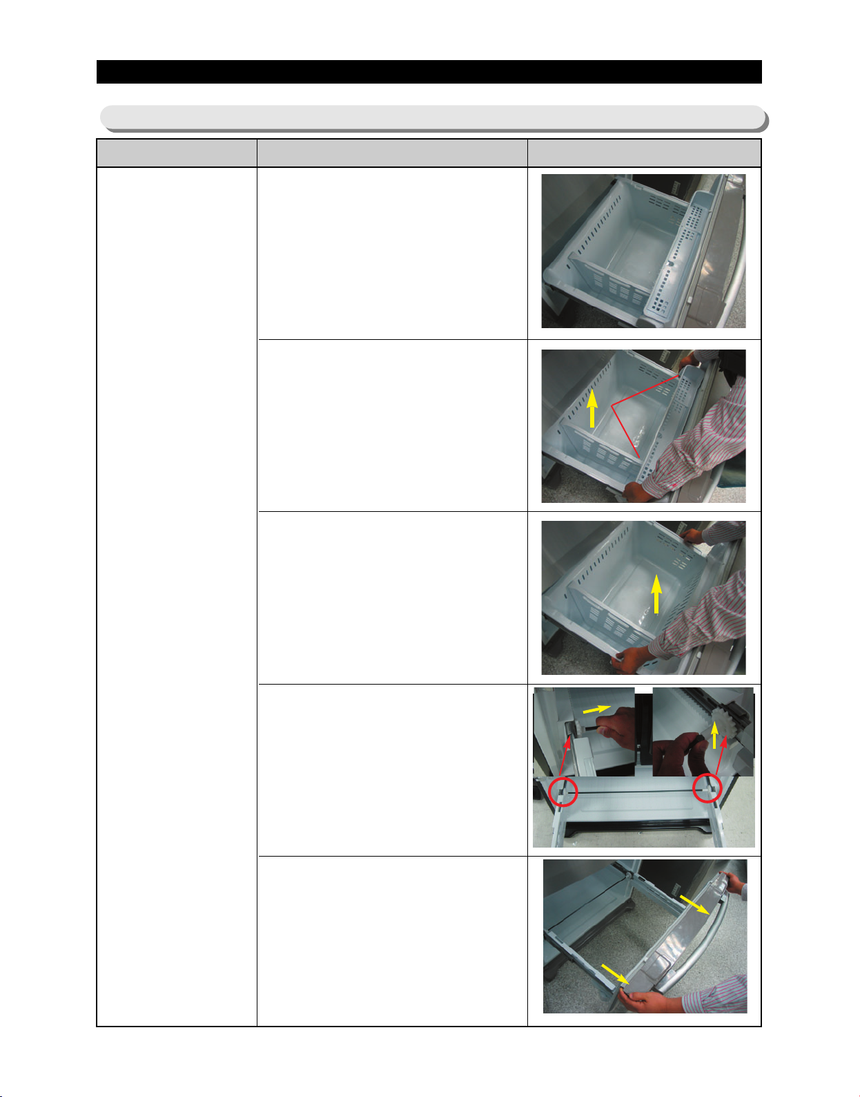
DISASSEMBLY AND REASSEMBLY
3-19) Freezer Door
Part Name How To Do Descriptive Picture
1. Pull the drawer open to full
extension.
Freezer
Door
2. Remove the tilting Pocket(①) by
pulling the both brackets(②)
upward at the same time.
3. Take out the lower basket(③) by
lifting the basket up from rail
system.
4. Remove a fixing pin(④) and
remove a shaft(⑤) by pushing it
to the right side with your hand.
①
②
③
④
⑤
5. Separate the rail from the rail
cover by pushing the hooks (⑥)
in on both sides of the rail. After
pusing the hooks in, remove the
drawer by pulling towards you
with both hands.
37
Page 39
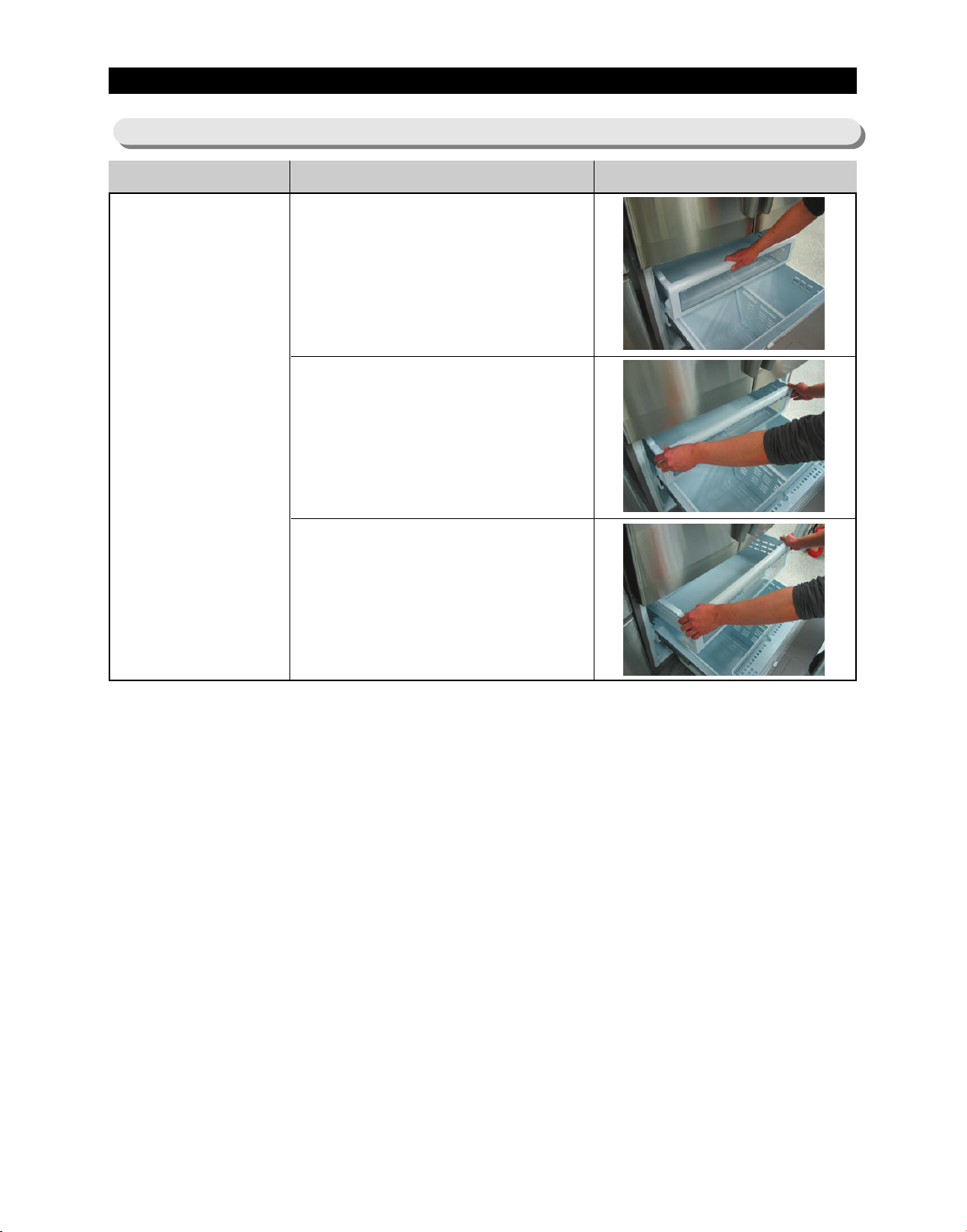
DISASSEMBLY AND REASSEMBLY
3-20) Pull Out Drawer
Part Name How To Do Descriptive Picture
1. Slide the drawer in as much as
possible
Door
Handle
Freezer
2. Lift the drawer up
3. Remove the pull out drawer by
lifting the bottom part of drawer
bin and pulling it out.
38
Page 40
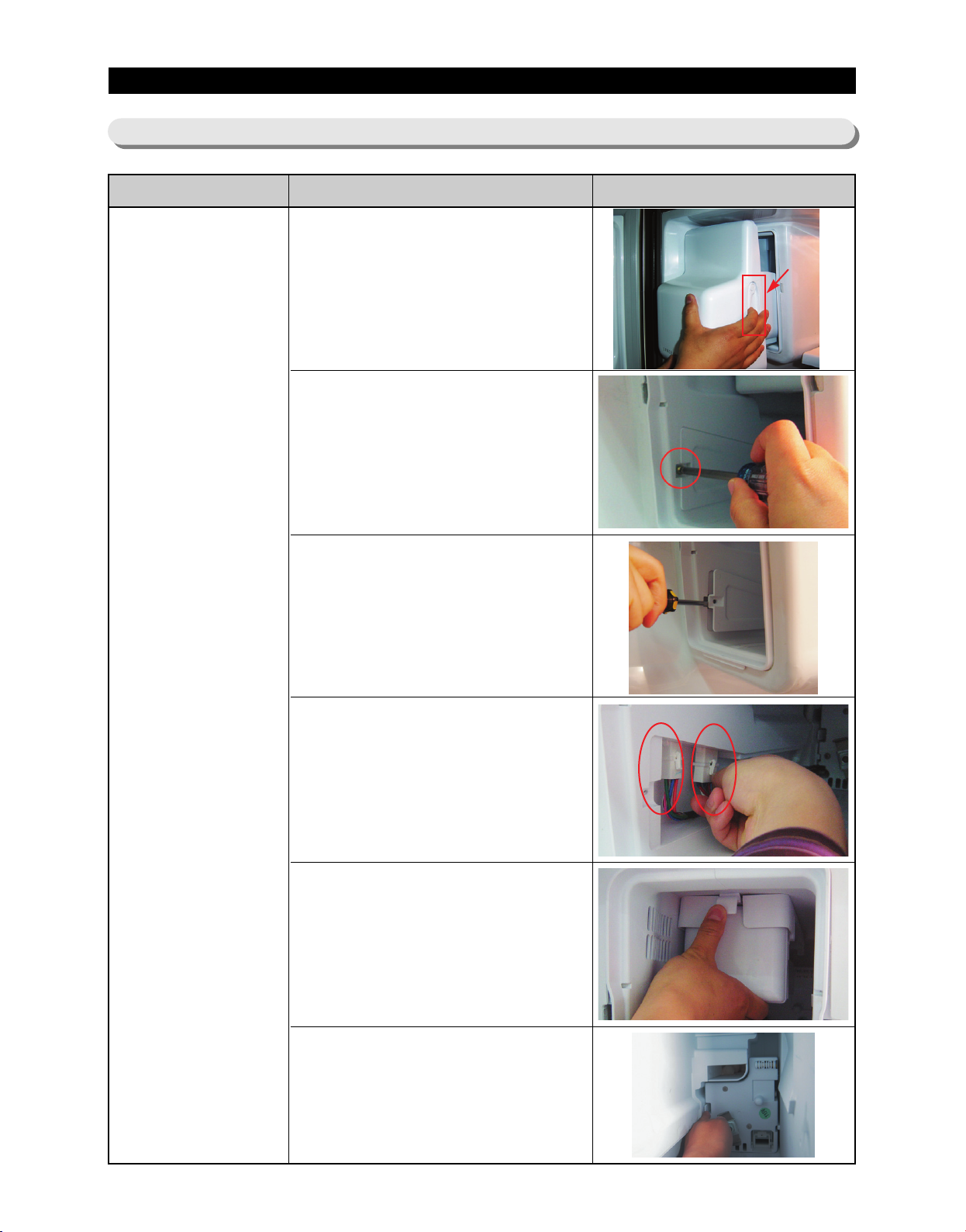
DISASSEMBLY AND REASSEMBLY
3-21) Ice-Maker
Part Name How To Do Descriptive Picture
1. Pull the Ice-Bucket lever and out
2. Remove 1 screw of the Cover
lever
Ice Maker
3. Disassemble the cover with a
flat-blade(-) screwdriver and pull
it out.
4. Disengage the 2 housing
connector.
5. Push hook and pull the IceMaker out.
6. To disassemble, push the tab
and pull the case-auger and the
motor out.
39
Page 41
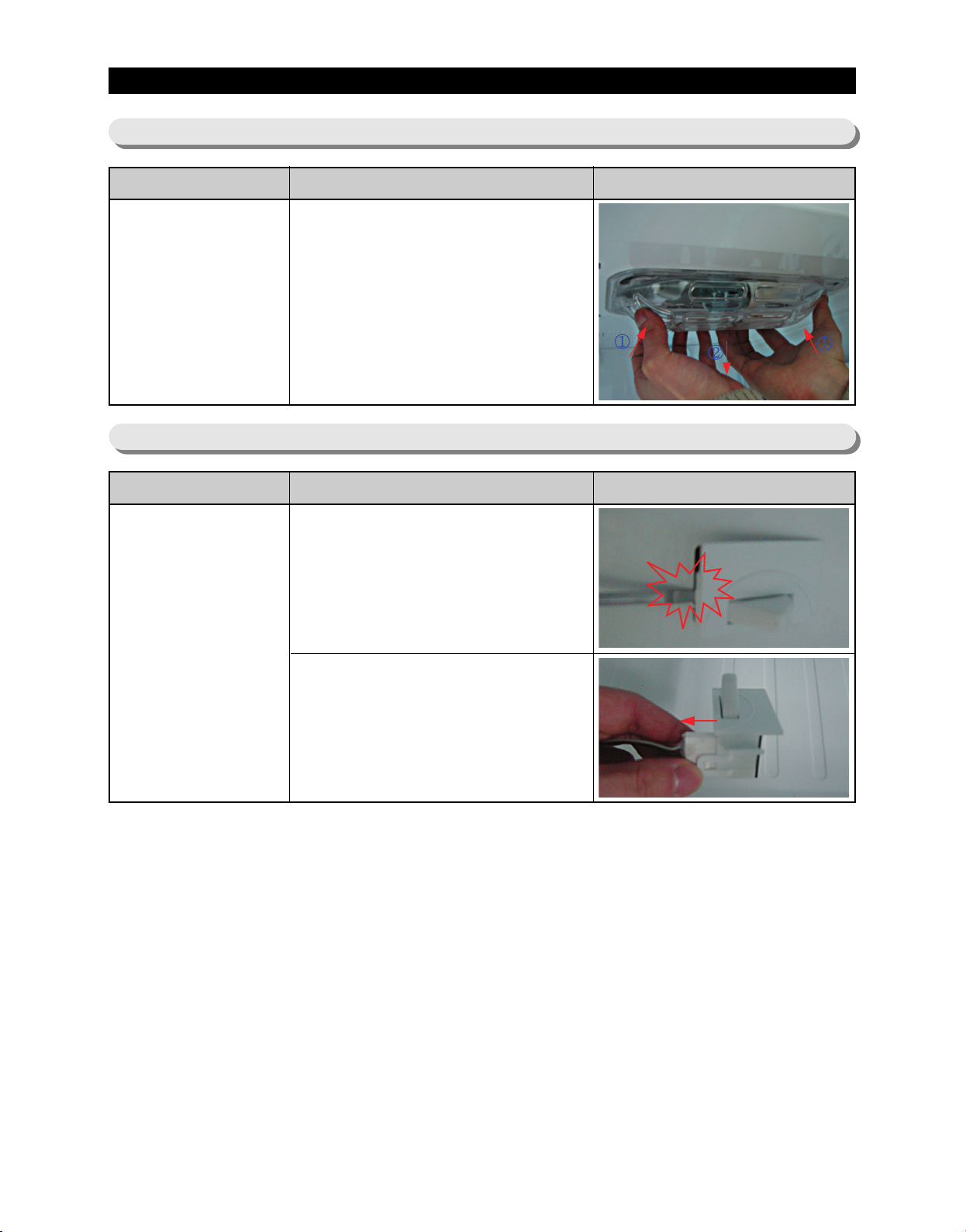
DISASSEMBLY AND REASSEMBLY
3-22) Freezer Light
Part Name How To Do Descriptive Picture
1. Remove the light by pulling the
Freezer Light
3-23) Door Switch In Freezer
Part Name How To Do Descriptive Picture
light cover down while pushing
the rear plane of light cover.
Door Switch In
Freezer
1. Remove the freezer drawer bin
by using a flat-blade(-)
screwdriver.(Refer to the
picture)
2. Disconnect the housing
connector part.
40
Page 42
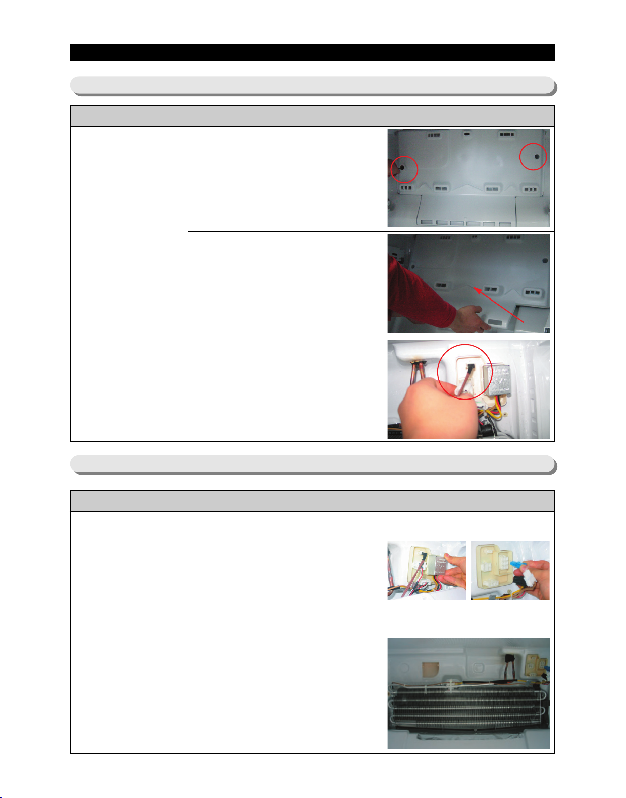
DISASSEMBLY AND REASSEMBLY
3-24) Evaporator Cover In Freezer
Part Name How To Do Descriptive Picture
1. Remove the freezer door and
freezer drawer bin by pulling out
the drawer and then unscrewing
2 screws.
Evaporator Cover
In
Freezer
2. Lift up the evaporator cover.
3. Disengage the 3 housing
connector and remove the
evaporator cover.
3-25) Evaporator In Freezer
Part Name How To Do Descriptive Picture
1. Remove the housing cover by
pushing both lateral sides of
housing cover part and pulling it
out.
Remove the housing connector
part.
Evaporator In
Freezer
2. Remove the evaporator by
pulling the lower part of the
evaporator while lifting it up.
41
Page 43
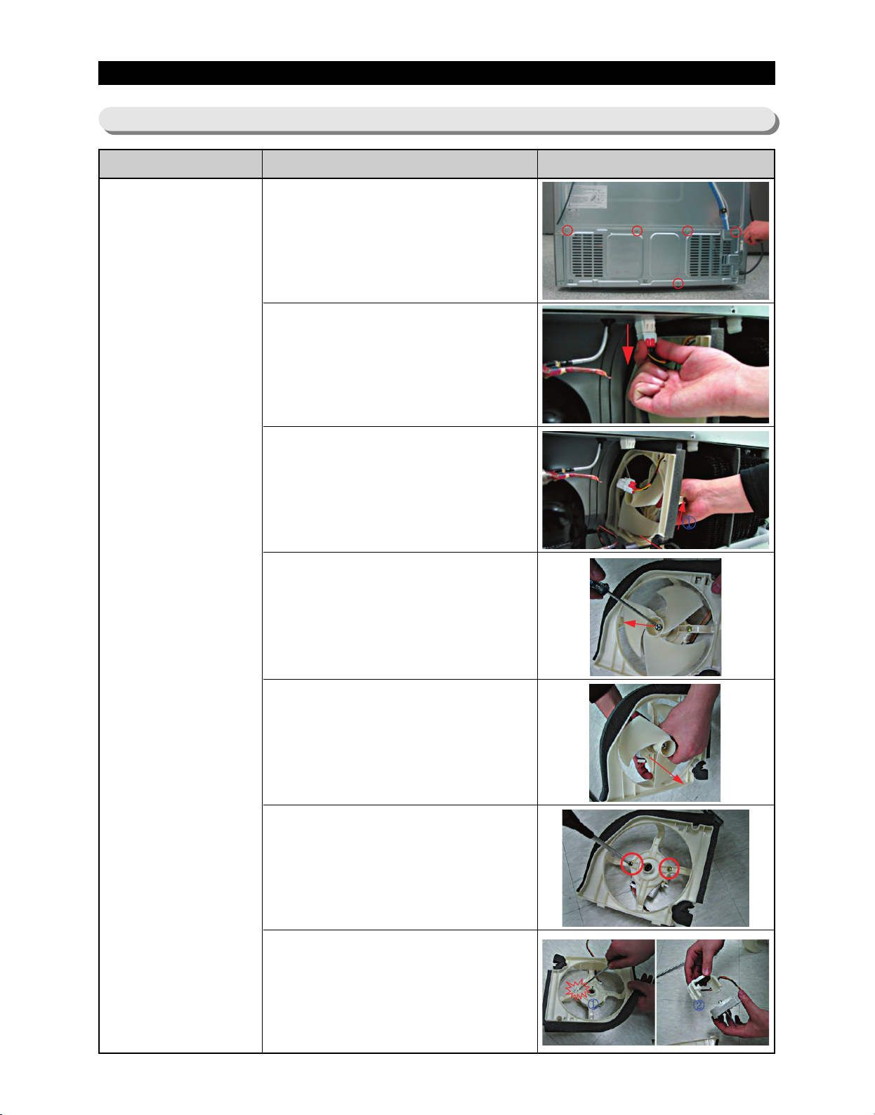
DISASSEMBLY AND REASSEMBLY
3-26) Machine Compartment
Part Name How To Do Descriptive Picture
1. Unscrew 5 screws of cover
compressor.
2. Disengage the housing
connector.
(Refer to the picture)
3. Remove the hooker of support
circuit motor by lifting the hooker
up and pulling it out.
Motor Fan
4. Remove the spring with a flatblade screwdriver.
(Refer to the picture)
5. Remove the motor fan by pulling
the fan out while grasping the
motor part.
(Refer to the picture)
6. Unscrew 2 screws fixed in the
motor.
7. Remove the hook of the motor
cover with a flat-blade (-)
screwdriver and then remove
the motor.
42
Page 44
DISASSEMBLY AND REASSEMBLY
Part Name How To Do Descriptive Picture
1. Disengage the housing
connector.
Relay O/L
2.Remove Cover Relay
3. Remove the relay O/L with a
flat-blade screwdriver.
(Refer to the picture)
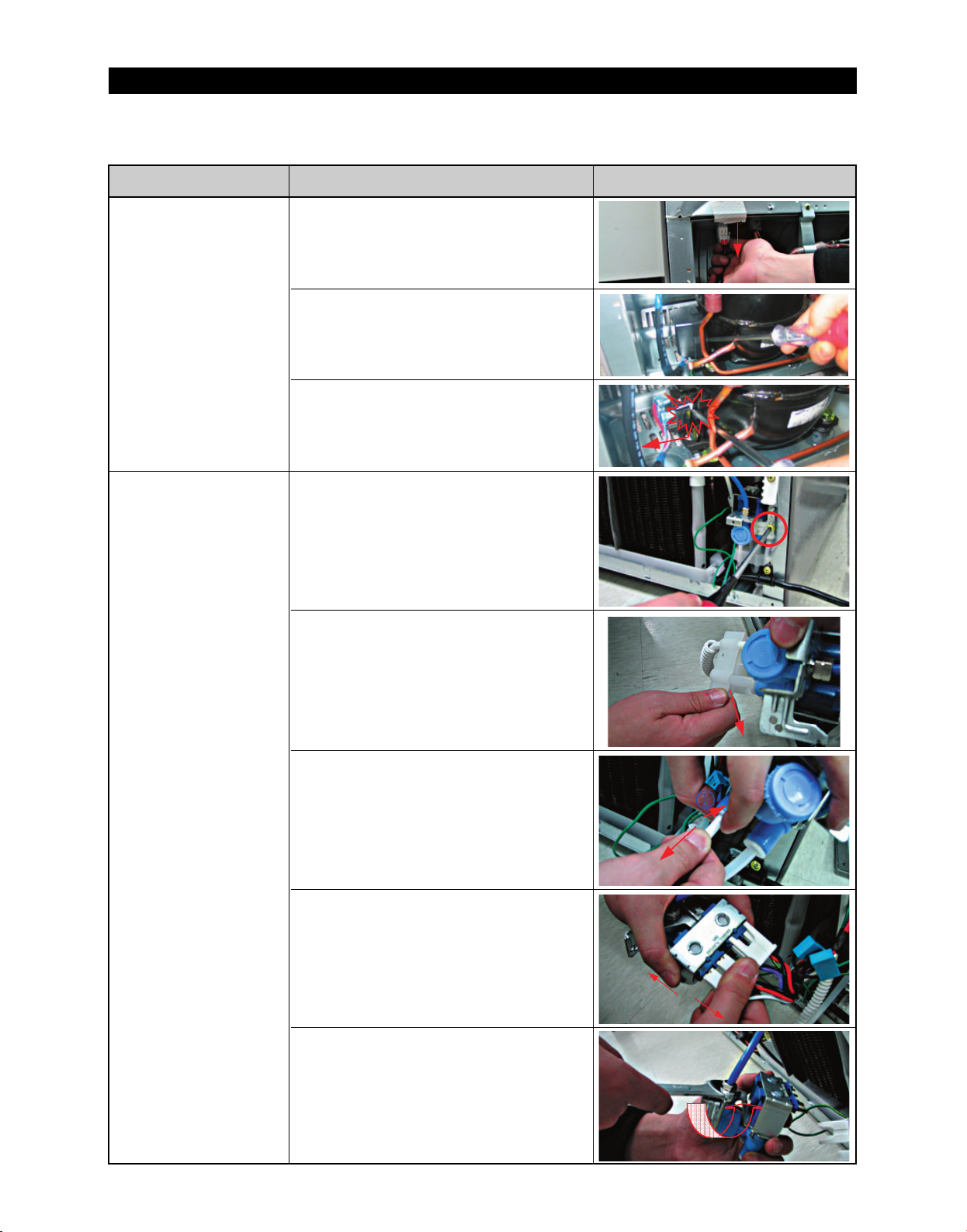
1. Unscrew the water valve fixed
by the screw.
2. Remove the the hook part of the
hose by pushing it down.
Water Valve
3. Remove 2 water hose parts
while pushing the upper part of
①.
(Refer to the picture)
4. Disengage 2 housing connector
parts.
5. Remove the hose connected by
the nut with a wrench(8mm).
43
Page 45
DISASSEMBLY AND REASSEMBLY
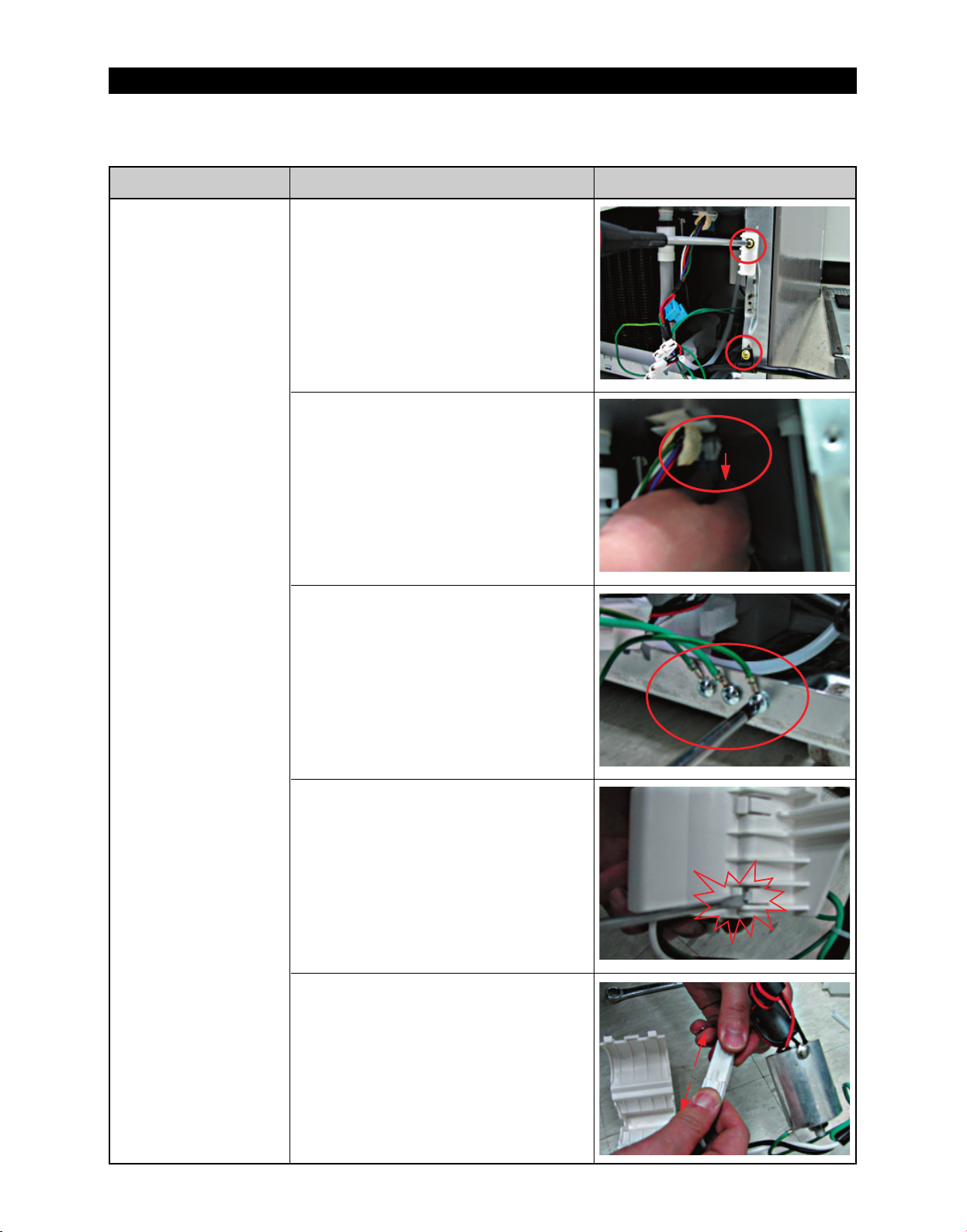
Part Name How To Do Descriptive Picture
1. Unscrew 2 screws.
2. Disengage the housing
connector.
Power Cord &
Noise Filter
3. Unscrew 3 earth screws.
4. Remove the cover by pushing
the hook up using a flat-blade(-)
screwdriver.
(Refer to the picture)
5. Disengage the housing
connector to separate the power
cord and noise filter.
44
Page 46
DISASSEMBLY AND REASSEMBLY
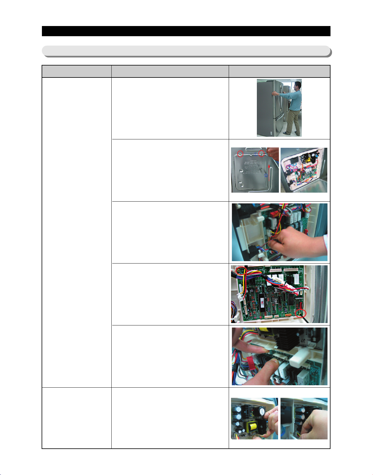
3-27) Electric Box
Part Name How To Do Descriptive Picture
1. Pull the refrigerator forward to
have enough space to work on
the rear side of the appliance.
2. Unscrew 2 screws for the PCB
cover.
PBA Main
PBA SMPS
3. Disengage all housing
connectors connected with main
PCB.
4. Unscrew 2 PCB fixed screws.
5. Remove the main PCB while
lifting the upper part of the hook
up.
(Refer to the picture)
1. Remove the cover PCB and
then disengage the housing
connector connected with main
PCB.
Remove the SMPS PCB while
pushing the lower part of the
hook down.
45
Page 47

4. TROUBLESHOOTING
4-1) FUNCTION FOR FAILURE DIAGNOSIS ························47
4-1-1. TEST MODE (MANUAL OPERATION / MANUAL DEFROST FUNCTION)
4-1-2. DISPLAY FUNCTION OF COMMUNICATION ERROR
4-1-3. SELF-DIAGNOSTIC FUNCTION
4-1-4. DISPLAY FUNCTION OF LOAD CONDITION
4-1-5. EXHIBITION MODE SETTING FUNCTION
4-1-6. OPTION SETTING FUNCTION
4-1-7. OPTION TABLE
4-2)
DIAGNOSTIC METHOD ACCORDING TO THE TROUBLE SYMPTOM(FLOW CHART)
·····································56
···························49
···················52
·····················53
····························53
4-2-1. IF THE TROUBLE IS DETECTED BY SELF-DIAGNOSIS
4-2-2. IF FAN DOES NOT OPERATE
4-2-3. IF ICE ROOM FAN DOES NOT OPERATE
4-2-4. IF ICE MAKER DOES NOT OPERATE
····························68
·····················69
·······················70
··············48
············58
···47
···57
4-2-5. IF DEFROST DOES NOT OPERATE (F,R DEF HEATER)
4-2-6. IF POWER IS NOT SUPPLIED
4-2-7. IF COMPRESSOR DOES NOT OPERATE
4-2-8.
WHEN ALARM SOUND CONTINUOUS WITHOUT STOP(RELATED WITH BUZZER SOUND)
4-2-9. IF PANEL PCB DOES NOT WORK NORMALLY
····························72
·····················73
··················76
4-2-10. IF PANTRY PANEL PCB IS NOT WORKING NORMALLY
············71
············77
4-2-11. WHEN REFRIGERATOR ROOM LAMP DOES NOT LIGHT UP
4-2-12. IF ICE WATER IS NOT SUPPLIED
4-2-13. IF WATER IS NOT SUPPLIED
4-2-14. IF CUBED OR CRUSHED ICE IS NOT SUPPLIED
4-2-15.
IF COVER ICE ROUTE MOOR(GEARD MOTOR) IS NOT WORKING NORMALLY
·························79
···························80
···············81
··74
········78
··82
46
Page 48
TROUBLESHOOTING
4-1) Function for failure diagnosis
4-1-1. Test mode (manual operation / manual defrost function)
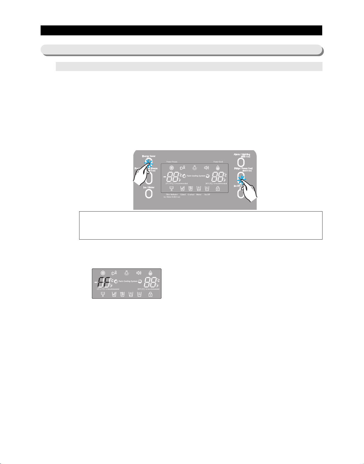
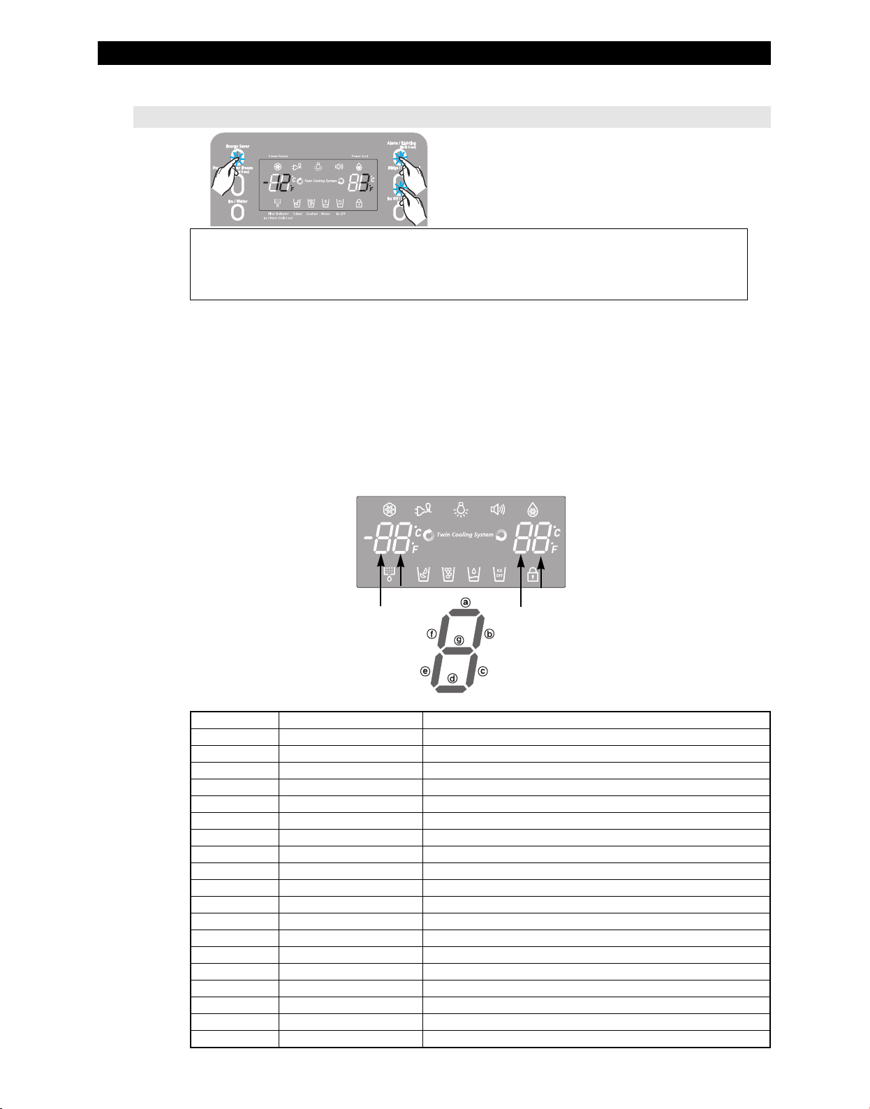
● If Energy Saver Key + Fridge/Power Cool Key on the front of panel are pressed simultaneously
for 8 seconds , it will be changed to the test mode and all displays on the front of panel will be off.
● If any key on the front of panel is pressed within 15 seconds after the test mode, it will be
operated as below sequence :
manual operation(fresh food compartment) → manual defrost of fresh food compartment(rd) →
manual defrost of fresh food and freezer compartments (Fd) → Cancel(Display all off).
● If any key on the front of panel is not pressed within 15 seconds after the test mode, the test
mode will be canceled and it will be returned to previous mode.
1) Manual operation function
①①
①①
① If Energy Saver Key + Fridge/Power Cool Key are pressed simultaneously for
8 seconds, (displays are all off)
It will be changed to the test mode (manual operation) by pressing any key
1-1) If any key is pressed once in test mode, blinks "FF" on the display and it indicates the
refrigerator has entered the manual operation. At this moment, buzzer beeps as an
alarm.
1-2) If manual operation is selected, compressor will run at once without 5 minutes delay in
any mode. If the refrigerator is on the defrost cycle at the moment, defrost will be
finished and manual operation will begin.
(Be careful if manual operation get started at the moment of compressor off, over load
could be occurred)
1-3) If manual operation works, compressor & f-fan operate continuously for 24 hours and
fresh food compartment will be controlled by the setting temperature.
1-4) When the manual operation runs, setting temperature will be selected automatically as
below: freezer compartment -14℉(-25℃), fresh food compartment 33.8℉(1℃).
1-5) During manual operation, Power Freeze & Power Cool function will not be worked.
If a function is selected, the power function icon of the selected function will be off
automatically after 10 seconds.
1-6) Manual operation can be canceled during manual operation by turning on the appliance
after power off(reset) or choosing the step 4) test cancel mode.
1-7) Alarm(0.25 sec ON/ 0.75 sec OFF) will beep continuously until manual operation is
completed and there is no function to make the sound stop.
47
Page 49
TROUBLESHOOTING
2) Manual defrost(fresh food compartment) function
2-1) If any key is pressed one more time during manual operation(fresh food compartment),
"rd" shows in the display and then manual operation will be canceled at once and fresh
food compartment will be defrosted.
2-2) At this moment, alarm beeps for 3 seconds(0.1 sec ON/ 1 sec OFF) during manual
defrost(fresh food compartment) function.
3) Simultaneous manual defrost(fresh food and freezer compartments) function
3-1) If any key is pressed one more time during manual defrost(defrost of fresh food
compartment, "rd"), "Fd" shows on the display and then fresh food and freezer
compartments defrost will operate.
Manual defrost of Fresh food and freezer compartments are followed by manual defrost
freezer compartment.
3-2) At this moment, alarm beeps for 3 seconds (0.5 sec ON/ 0.5 sec OFF) during manual
defrost function of fresh food and freezer compartment.
4) Test cancel mode
4-1) During defrosting of fresh food and freezer compartments simultaneously, if the display
panel change to the test mode and test button is pressed one more time, defrosting of
fresh food and freezer compartments will be canceled at the same time and will return
to the normal operation.
Or, all test functions will be canceled by turning main power ON and OFF.
4-1-2. Display function of Communication error
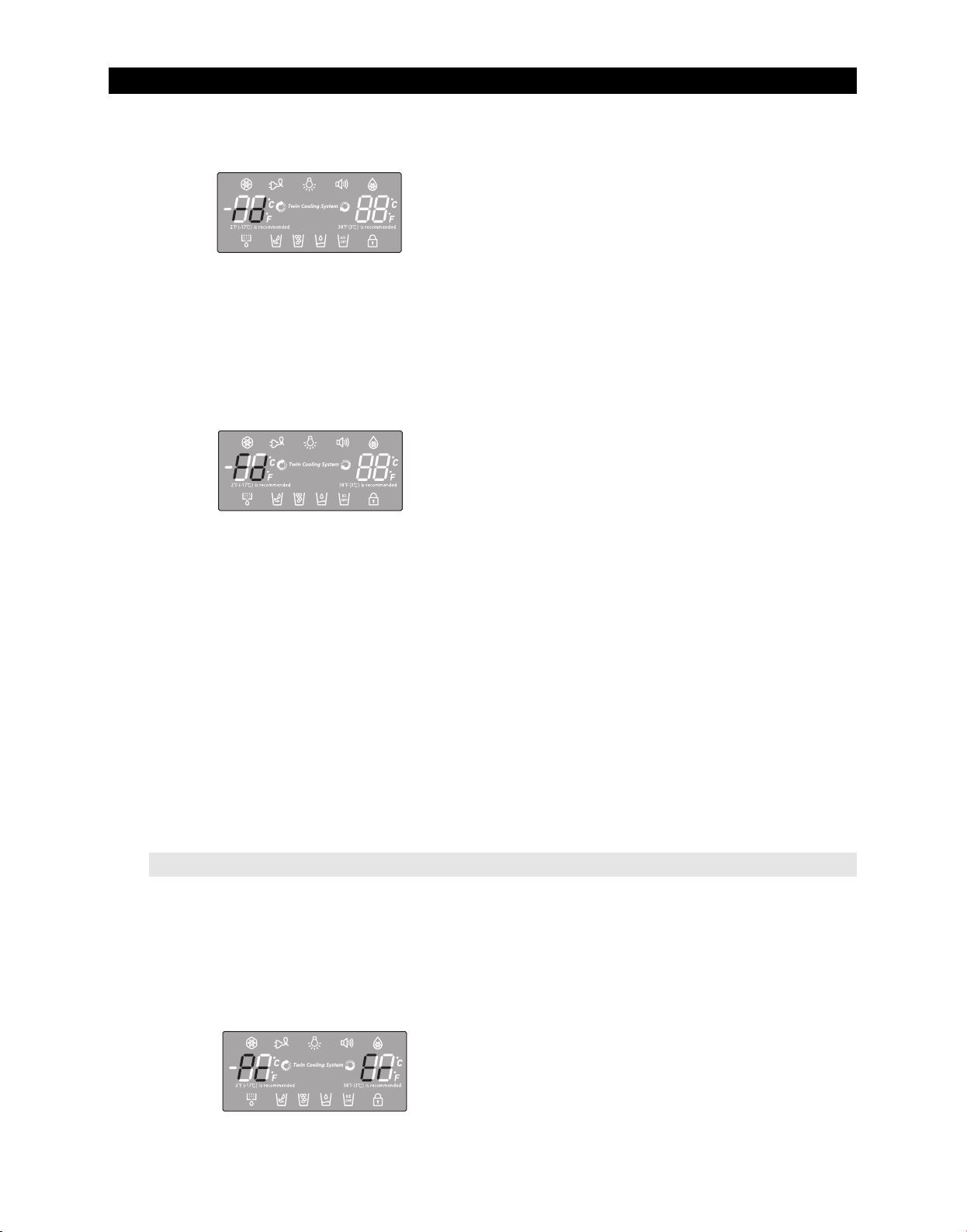
1) Display function when Panel ↔ MAIN MICOM communication has error
1-1) If there is no answer for 10 seconds after the panel micom received the requirement of
communication, "Pc - Er" display on the panel PCB will be ON/OFF alternately until the
communication error is canceled. (0.5 sec ALL ON, 0.5 sec ALL OFF alternately)
(0.5 sec ALL ON, 0.5 sec ALL OFF alternately)
48
Page 50
TROUBLESHOOTING
2¢(-17¡) is recommended 38¢(3¡) is recommended
2¢(-17¡) is recommended 38¢(3¡) is recommended
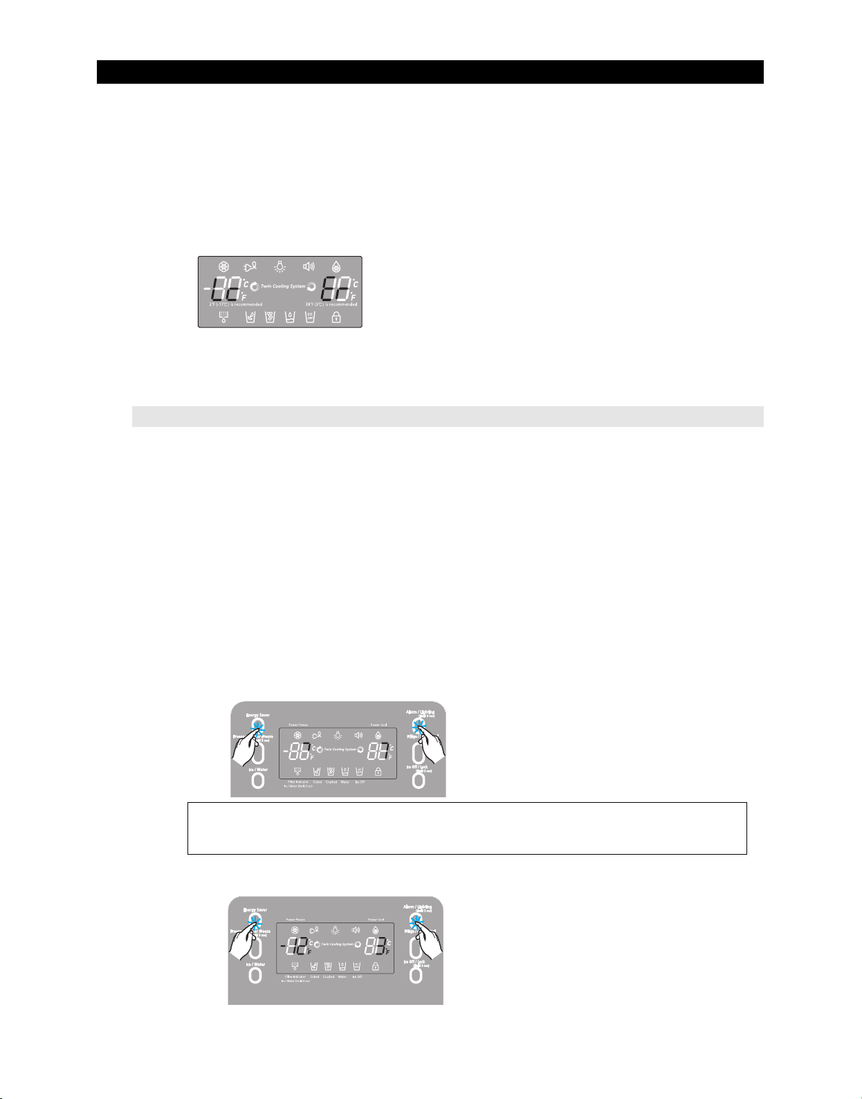
2) Display function when MAIN ↔ LOAD MICOM communication has error
2-1) If there is no answer for 20 seconds after the main micon received the requirement of
communication from load MICOM, "Lc - Er" display on the panel PCB will be ON/OFF
alternately until the communication error is canceled.
(0.5 sec ALL ON, 0.5 sec ALL OFF alternately)
2-2) Also pantry room display will be ON/OFF alternately until the communication error is
canceled.
(0.5 sec ALL ON, 1.5 sec ALL OFF alternately)
4-1-3. Self-diagnostic function
1) Self-diagnostic function in the Initial power ON
1-1) Micom operates self-diagnostic function to check the temperature sensor condition
within 1 second when the refrigerator turned On initially.
1-2) If bad sensor is detected by the self-diagnostic function, the applicable display LED will
blink for 0.5 sec.
At this moment, there is no beep sound.(Refer to self-diagnostic CHECK LIST)
1-3) Self-diagnostic button is recognized only when the error is displayed by the bad sensor.
Display does not operate normally but temperature control will be controlled by the
emergency operation.
1-4) When the error is detected by self-diagnosis, the error can be canceled automatically if
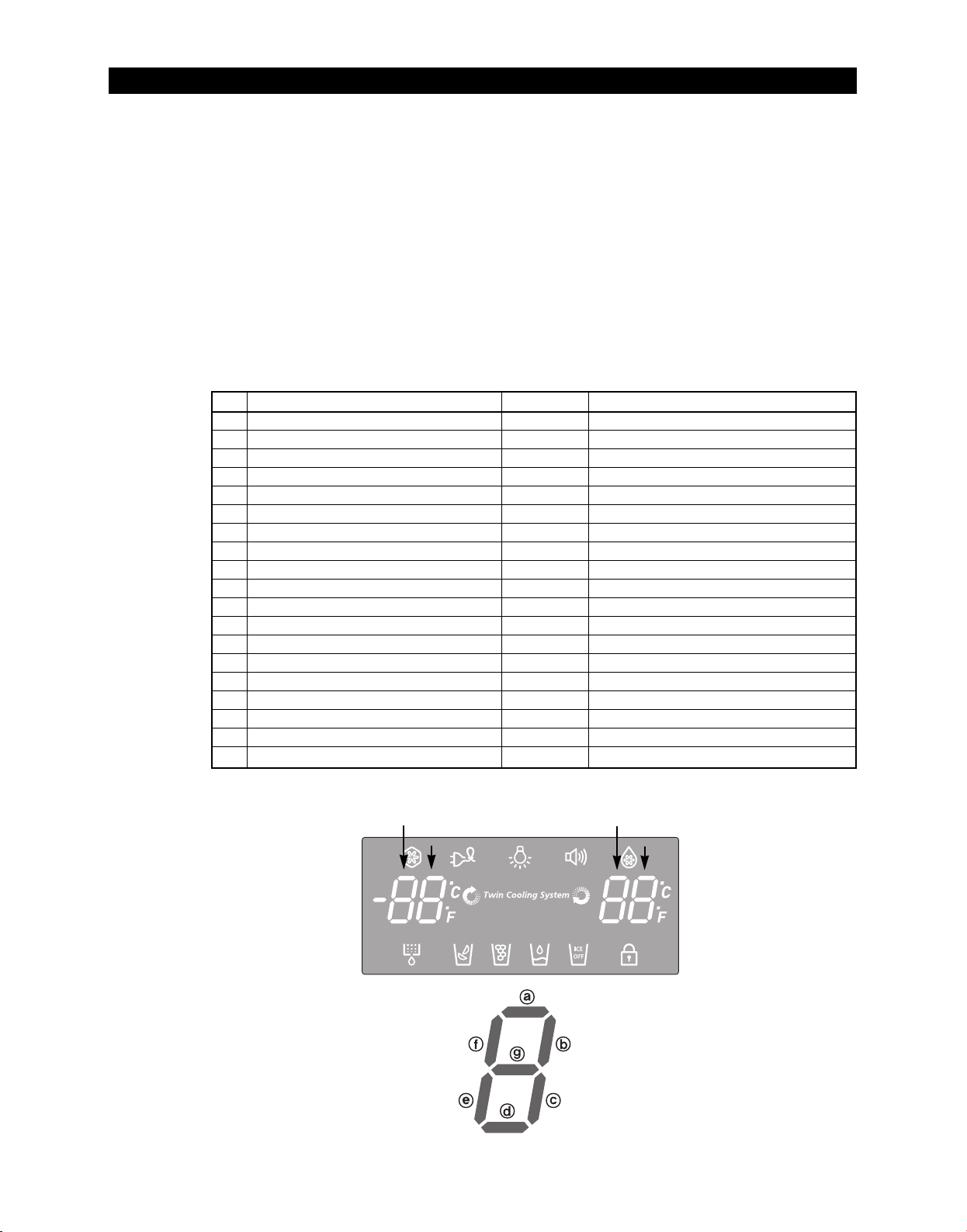
all troubled sensors are corrected or Self-diagnostic function key (Energy Saver Key +
Alarm/Lighting Key ) are pressed simultaneously for 8 seconds.
(Return to normal display mode)
①①
① If Energy Saver Key + Alarm/Lighting Key are pressed simultaneously
for 8 seconds, the error mode by self-diagnosis will be canceled.
2) Self-diagnostic function during normal operation
①①
①①
①①
49
Page 51
TROUBLESHOOTING
2¢(-17¡) is recommended 38¢(3¡) is recommended
2-1) If Energy Saver Key + Alarm/Lighting Key are pressed simultaneously for 6 seconds
during normal operation, the temperature setting display will operate for 2 seconds
(ON/OFF 0.5sec each).
If Energy Saver Key + Alarm/Lighting Key are pressed simultaneously for 8 seconds
(including above 2 seconds), self-diagnostic function will be selected.
2-2) At this moment, self-diagnostic function will be returned with buzzer sound 'ding-dong'.
If there is an error, display of error will be operated for 30 seconds and then return to
normal condition whether problem is corrected or not.
(Refer to self-diagnosis CHECK LIST)
2-3) Input by button is not accepted during self-diagnostic function.
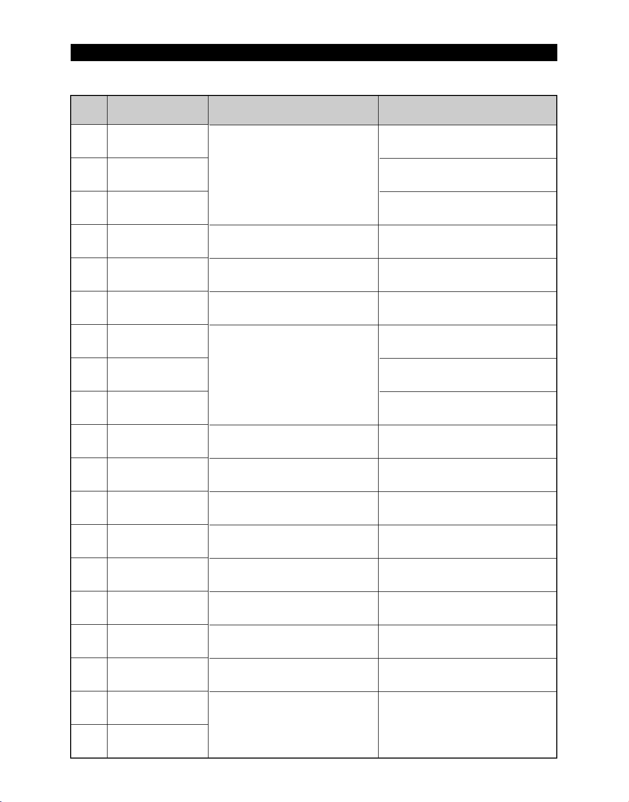
Self-diagnosis CHECK LIST
NO
Ice Maker Sensor Error
1
R-Sensor Error
2
R-DEF-Sensor Error
3
R-FAN Error
4
Ice Maker Error
5
R-DEF, Heater Error
6
Ambient-Sensor Error
7
F-Sensor Error
8
F-DEF-Sensor Error
9
F-FAN Error
10
C-FAN Error
11
Ice Room-Sensor Error
12
F-DEF.-Heater Error
13
Ice Room FAN Error
14
Pantry-Damper-Heater Error
15
Pantry-Sensor Error
16
Panel↔Main Micom Error
17
L↔M communication Error
18
Water Tank-Heaer Error
19
Trouble item
F-10
F-1
Display LED
R-1-ⓐ
R-1-ⓑ
R-1-ⓒ
R-1-ⓓ
R-1-ⓔ
R-1-ⓖ
F-1-ⓐ
F-1-ⓑ
F-1-ⓒ
F-1-ⓓ
F-1-ⓔ
F-1-ⓕ
F-1-ⓖ
F-10-ⓑ
R-10-ⓐ
R-10-ⓑ
F-10-ⓖ
F-10-ⓕ
R-10-ⓖ
Trouble contents
ICE MAKER SENSOR part error
R SENSOR part error
R defrost SENSOR part error
R inner part error
ICE MAKER operation error
R defrost part error
external SENSOR part error
F SENSOR part error
F defrost SENSOR part error
F inner fan motor part error
machine room fan motor part error
ICE ROOM SENSOR part error
F defrost part error
ICE ROOM inner fan motor part error
Damper Heater open/wire error
Pantry Room SENSOR part error
Panel↔Mai Micom communication error
LOAD↔Main Micom communication error
Water Tank Heater open/wire error
R-10
R-1
50
Page 52
TROUBLESHOOTING
Self-diagnostics check list
LED
R-1-ⓐ
R-1-ⓑ
R-1-ⓒ
R-1-ⓓ
R-1-ⓔ
R-1-ⓖ
F-1-ⓐ
F-1-ⓑ
F-1-ⓒ
Item
Ice Maker Sensor Error
R-Sensor Error
R-DEF-Sensor Error
R-FAN Error
Ice Maker Error
R-DEF. Error
Ambient-Sensor Error
F-Sensor Error
DEF-Sensor Error
Trouble contents
When checking the voltage of MAIN PCB CN90
Display error : separation of sensor housing
#3↔CN90#4 : should be between 4.5V~1.0V.
part, contact error, disconnection, short
circuit
Display error of detecting temperature of
sensor: more than 149℉ (+65°C) or less
than -58℉(-50°C)
Display error during operation of applicable
fan motor : Feed Back signal line contact
error, separation of motor wire, motor error
Display error : ice making kit is harvested
more than 3 times and level error
** Apply to the applicable Ice Maker model.
Display error : separation of fresh food compartment defrost heater housing
part, contact error, disconnection, short circuit or temperature fuse error.
Display error : the defrosting does not finish though fresh food compartment
defrost is heating continuously for more than 80 minutes.
When checking the voltage of MAIN PCB
CN30#6↔CN75#1: should be between 4.5V~1.0V
When checking the voltage of MAIN PCB
CN30#7↔CN75# : should be between 4.5V~1.0V
Voltage of MAIN PCB CN75 Orange ↔ Gray
should be between 7V~12V
After replacing ice maker, check the operation
by turning the appliance ON again.
After separating MAIN PCB CN70,CN71 from PCB, check the resistance value
between CN70 White ↔ CN71 Orange should be 102(441) ohm ± 7%.
(resistance value is varied by the input power)
Check 0 Ohm : heater short, ∞ Ohm : wire / bimetal Open.
When checking the voltage of MAIN PCB
Display error : sensor housing separation,
contact error, disconnection, short circuit
Display error by detecting temperature of
CN32#1↔#4 : should be between 4.5V~1.0V.
When checking the voltage of MAIN PCB
CN30#3↔CN75#1: should be between 4.5V~1.0V
sensor: more than 149℉(+65°C) or less
than -58℉(-50°C)
When check the voltage of MAIN PCB
CN30#4↔CN75#1: should be between 4.5V~1.0V
Diagnostic method
F-1-ⓓ
F-1-ⓔ
F-1-ⓕ
F-1-ⓖ
F-10-ⓑ
R-10-ⓐ
R-10-ⓑ
R-10-ⓖ
F-10-ⓖ
F-10-ⓕ
Display error during operation of applicable
F-FAN Error
C-FAN Error
Ice Room Sensor Error
F-DEF. Error
Ice Room-FAN Error
Pantry-Damper-Heater Error
Pantry-Sensor Error
Water Tank-Heater Error
Panel↔Main communication Error
fan motor : Feed Back signal line contact
error, motor wire separation, motor error
Display error during operation of applicable
fan motor : Feed Back signal line contact
error, motor wire separation, motor error
Display error : sensor housing separation,contact error,
disconnection, short circuit.
Display error by detecting temperature of sensor: more
than 149℉ (+65°C) or less than -58℉ (-50°C)
Display error : separation of freezer compartment defrost heater housing
part , contact error, disconnection, short circuit or temperature fuse error.
Display error : the defrosting does not finish though fresh food compartment
compartment defrost is heating continuously for more than 70 minutes.
Display error during operation of applicable fan motor :
Feed Back signal line contact error, motor wire separation,
motor error
Display error when open error is detected by damper
heater : separation of Damper Heater housing part,
contact error, disconnection, short circuit
Display error : separation of sensor housing, contact error,
disconnection, short circuit.
Display error by detecting temperature of sensor: more than 149℉
(+65°C) or less than -58℉(-50°C)
Display error when open error is detected by Water Tank
Heater : separation of Water Tank Heater housing
part,contact error, disconnection, short circuit
Display "oP/LC-Er" in the panel with alarm :
MICOM MAIN ↔ LOAD communication error
MICOM MAIN ↔ PANEL communication error
Load↔Main communication Error
LC-Er is displayed when the Option is not
equivalent with the right value
Voltage of MAIN PCB CN75 Yellow ↔ Gray
should be between 7V~12V.
Voltage of MAIN PCB CN75 Sky-blue ↔ Gray
should be between 7V~12V.
When check the voltage of MAIN PCB
CN32#3↔CN75#1: should be between 4.5V~1.0V
After separating MAIN PCB CN70,CN71 from PCB, check the
resistance value between CN70 brown ↔ CN71 Orange should be
102(220) ohm ± 7%. (resistance value is varied by input power)
Check 0 Ohm : heater short, ∞ Ohm : wire / bimetal Open.
Voltage of MAIN PCB CN76 Black ↔ CN75 Gray : should be
between 6V~12V.
After separating MAIN PCB CN91from PCB, check the resistance
value between Black ↔ brown wire should be 145 ohm ± 7%.
Check 0 Ohm : heater short, ∞ Ohm : wire / bimetal Open.
When checking the voltage of MAIN PCB
CN30#8 ↔ #9 : should be between 4.5V~1.0V.
After separating MAIN PCB CN78from PCB, check the resistance
value between Black
Check 0 Ohm : heater short,
↔
brown wire should be 48 ohm 7%.
∞
Ohm : wire / bimetal Open.
Actually, it is desirable to recheck the condition with
the oscilloscope(1G Hz) after replacing Main and
Panel PCB.
51
Page 53
TROUBLESHOOTING
2¢(-17¡) is recommended 38¢(3¡) is recommended
2¢(-17¡) is recommended 38¢(3¡) is recommended
4-1-4. Display function of Load condition
①① ①①
① If Energy Saver Key + Alarm/Lighting key are pressed simultaneously for 6
seconds, ALL ON/OFF will blink with 0.5interval for 2 seconds.
② If take the finger off from above keys and press Fridge/Power Cool Key, load
condition mode will be started.
1) If Power Energy Saver Key + Alarm/Lighting key are pressed simultaneously for 6 seconds during normal
operation, the temperature setting display of fresh food and freezer compartments will blink ALL ON/OFF with
0.5 for 2 seconds.
2) At this moment, If Fridge/Power Cool Key after Energy Saver Key + Alarm/Lighting Key is pressed, load
condition display mode will be returned with alarm.
3) Load condition display mode shows the load that micom signal is outputting.
However, It means that micom signal is outputting, it does not mean whether load is operating or not. That is to
say that though load operation is displayed, load could not be operated by actual load error or PCB relay error
etc. (This function would be applied at A/S.)
4) Load condition display function will maintain for 30 seconds and then normal condition will be returned
automatically.
5) Load condition display is as below.
②②
Load mode Check list
Display LED
R-1-ⓐ
R-1-ⓑ
R-1-ⓒ
R-1-ⓓ
R-1-ⓔ
R-1-ⓕ
F-1-ⓔ,ⓕALL LED Off
R1-ⓖ
F-1-ⓐ
F-1-ⓑ
F-1-ⓒ
F-1-ⓓ
R-10-ⓔ
R-10-ⓕ
F-10-ⓖ
F-1-ⓖ
F-10-ⓐ
F-10-ⓓ
F-10-ⓔ
R-FAN High
R-FAN Low
R-DEF Heater
Start Mode
Overload condition
Low temperature condition
Normal Condition
Exhibition Mode
COMP.
F-FAN High
F-FAN Low
F-DEF Heater
C-FAN High
C-FAN Low
French Heater
Dispenser Heater
Water Tank Heater
Ice Room-FAN High Ice
Ice Room-FAN Low
F-10
Display contents
F-1
When fresh food compartment fan high operates, applicable LED ON
When fresh food compartment fan low operates, applicable LED ON
When fresh food compartment defrost heater operates, LED ON
Initial power ON refrigerator, LED ON
When ambient temperature is more than 93℉(34°C), LED ON
When ambient temperature is less than 72℉(22°C), LED ON
When ambient temperature is between 73℉(23°C) ~ 91℉(33°C), LED ON
Display mode, LED ON
When compressor operates, applicable LED ON
When freezer compartment fan high operates, applicable LED ON
When freezer compartment fan low operates, applicable LED ON
When freezer compartment defrost heater operates, LED ON
When compressor fan high operates, applicable LED ON
When compressor fan low operates, applicable LED ON
When french heater operates, applicable LED ON
When dispenser heater operates LED ON
When water tank heater operates LED ON
When Ice room fan high operates LED ON
When Ice room fan low operates LED ON
R-1
R-10
Operation contents
52
Page 54
TROUBLESHOOTING
2¢(-17¡) is recommended 38¢(3¡) is recommended
2¢(-17¡) is recommended 38¢(3¡) is recommended
4-1-5. Exhibition mode setting function
①①
①①
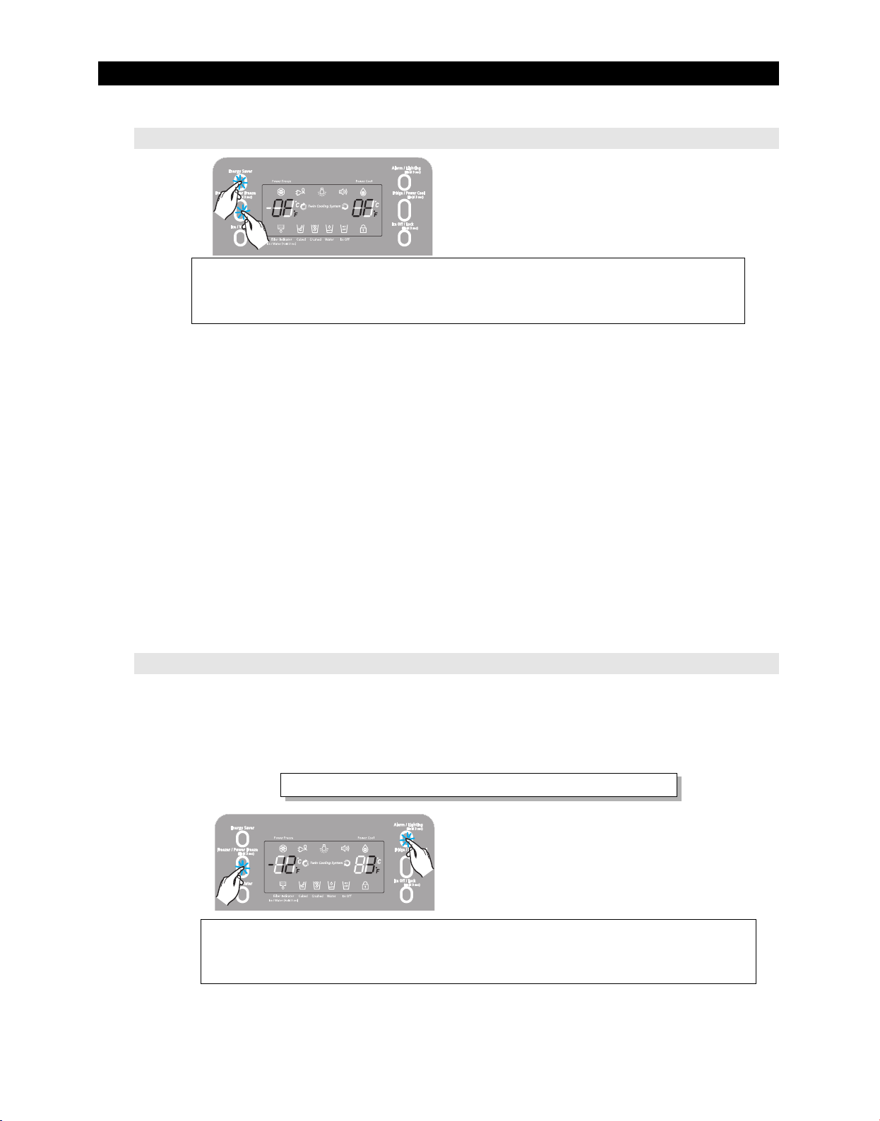
① If Energy Saver Key + Power Freeze Key are pressed for 3 seconds, show room
mode will be started.
1) If Energy Saver Key + Freezer/Power Freeze are pressed simultaneously for 3 seconds during
normal operation, show room mode will be started with buzzer sound(ding-dong).
2) If above Energy Saver Key + Freeze/Power Freeze are pressed one more time, show room
mode will be canceled.
3) If show room mode is selected, blinks "OF-OF" on the temperature setting display of the panel
and it indicates the refrigerator has entered the show room mode.
4) During show room mode, if fresh food and freezer compartments sensors are higher than
149℉(65℃) show room mode will be canceled automatically and freezing operation will be
returned.
(There is no buzzer sound when the show room mode is canceled by the temperature)
5) Operation contents of show room mode
- Display, Fan motor and etc operate normally, not to operate compressor only.
- Defrost is not operated. (including french heater)
- Display function of the initial real temperature is finished.
- Under the condition of show room mode, show room mode will be operated when Power On
after Power OFF.
4-1-6. Option setting function
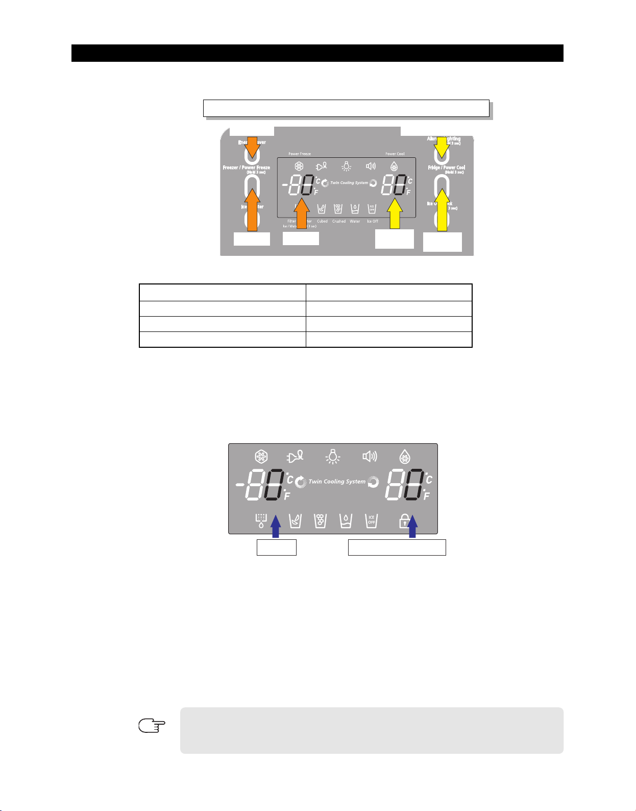
● If Freezer/Power Freeze Key+ Alarm/lighting Key are pressed simultaneously for 12 seconds
during normal operation, fresh food and freezer compartments temperature display will be
changed to option setting mode.
KEY operation method for changing to option mode
① If Freezer/Power Freeze Key+ Alarm/lighting Key are pressed simultaneously for 12
seconds, option setting mode will be started.
53
Page 55
TROUBLESHOOTING
Code Up
Code
Reference
Value
Reference
Value Up
Code Down
Reference Value Down
2¢(-17¡) is recommended 38¢(3¡) is recommended
Reference ValueCode
2¢(-17¡) is recommended 38¢(3¡) is recommended
Key control in option mode
KEY control method after converting to option mode
Energy Saver
Freezer/Power Freeze
Alarm/Lighting
Fridge/Power Cool
Code Down key
Code Up key
Reference Value down key
Reference Value Up key
● If the display changes to option setting mode, all displays will be off except freezer and
fridge compartments temperature display as below.
(Fresh food and freezer compartments case will be explained only because all options
are operated with the same method according to the option table.)
1) For example, if you want to change freezer compartment standard temperature to 28.4℉(-
2°C) by operating option, do as below.
This function is for changing the standard temperature.
In -2℉(-19°C) of current temperature of freezer compartment, if you make the temperature
lower to 28.4℉(-2°C) by the option, the standard temperature would be controlled -6℉(-21°C)
Therefore, if you change the setting of temperature option to -2℉(-19°C) on the panel, the
appliance will be operated with -6℉(-21°C).
It means that standard temperature is controlled 28.4℉(-2°C) less than setting temperature in
the display.
Basically, option function has cleared data at shipping process.
Therefore, almost all setting value are "0".
NOTE
Check the product information manual or specifications because setting value could be
changed particularly for the purpose of improving product at mass producing process.
54
Page 56
TROUBLESHOOTING
Reference ValueCode
2¢(-17¡) is recommended 38¢(3¡) is recommended
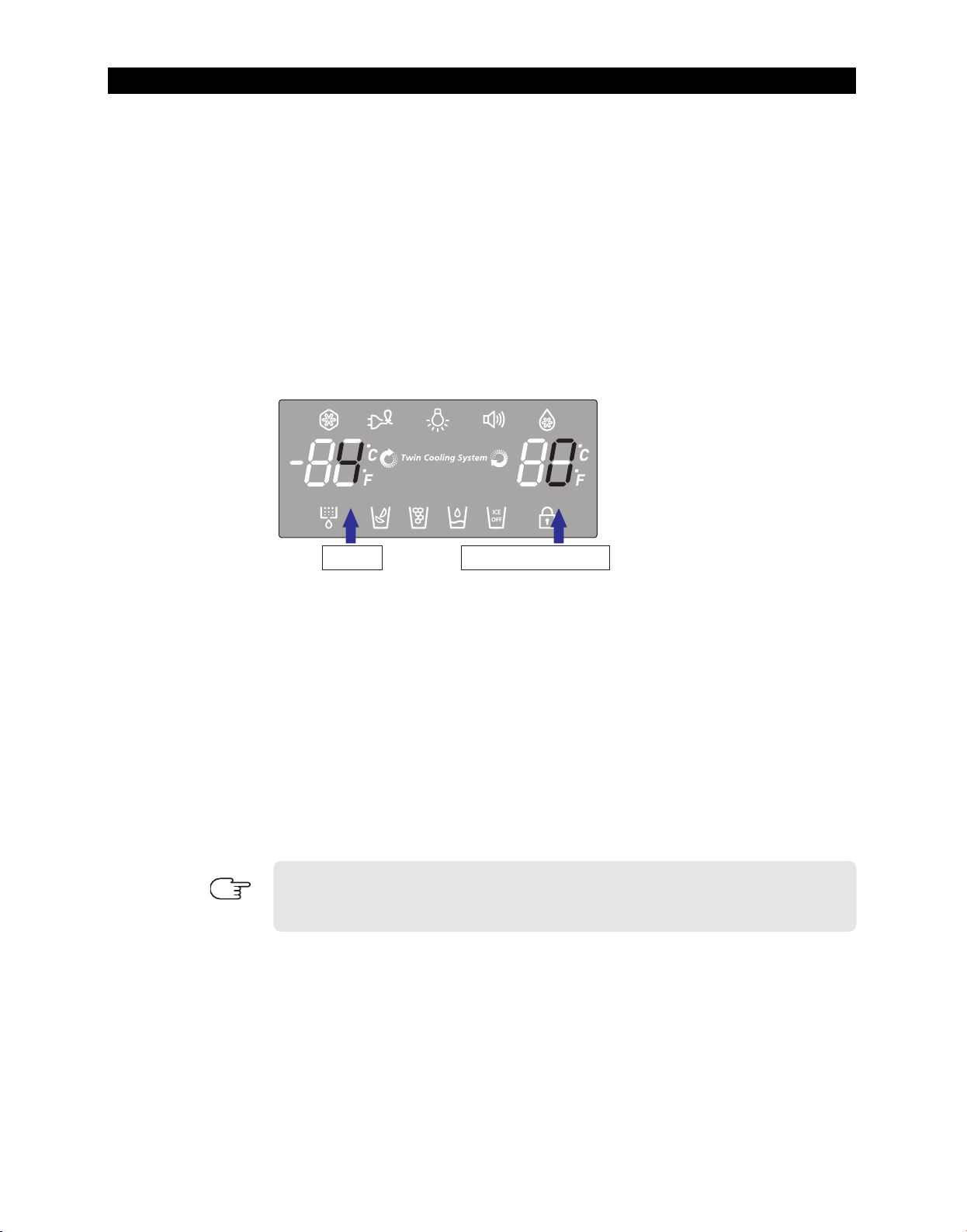
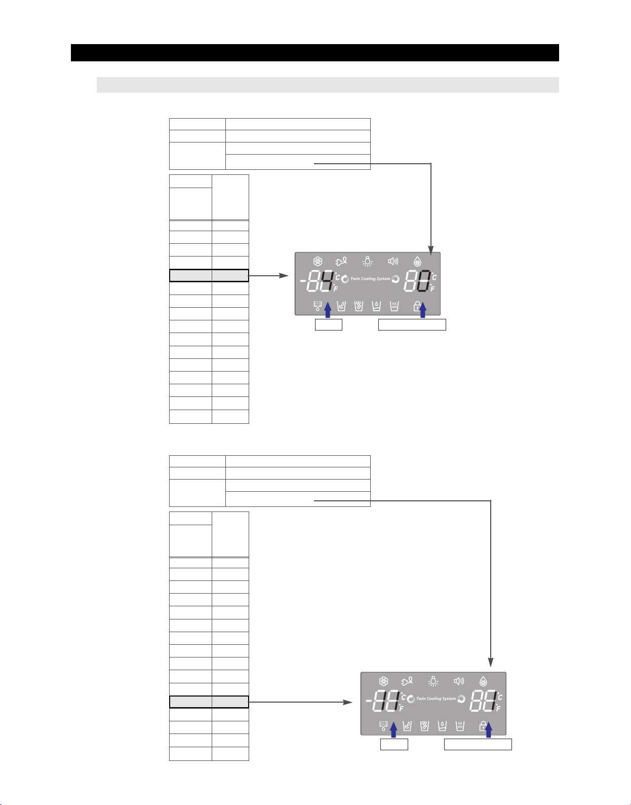
2) After changing to the option mode, fresh food compartment "0" , freezer compartment
"0" will be displayed. ( Basically fresh food compartment "0", freezer "0" would be set at
shipping process, but setting value could be changed for the purpose of improving
product at mass producing process.)
- If fresh food compartment "0" shows only, temperature reference value of freezer
compartment will be set and current freezer compartment temperature code will be
displayed on the freezer temperature display.
3) If freezer compartment "4" is set as below freezer compartment code after fresh food
compartment "0 is set, standard temperature of freezer compartment will be lower than
28.4℉(-2.0°C).
(Refer to the picture "changing the freezer compartment temperature")
: If you wait for 20 seconds after completing the setting, MICOM will save the setting value
to the EEPROM and normal display will be returned and the option setting mode will be
canceled.
4) Option changing method as above is the same as all RF266/265** model.
5) By the same method as above, it is possible to control the fresh food compartment
temperature, water supply, ice-maker harvest temperature/time, defrost return time,
hysteresis by temperature, notch gap by temperature etc.
6) Option function is set in the EEPROM at shipping process in the factory.
You would better not to change the option of your own.
Completing the setting is that option function return to normal display after 20 seconds.
Do not turn off the appliance before returning to the normal display mode.
Option setting function exists in the other items.
We will skip the explanation of the other functions by the option because it is
NOTE
associated with refrigerator control function and is not needed at SERVICE.
(Please do not set the other options except above SERVICE Manual.)
55
Page 57
Reference ValueCode
2¢(-17¡) is recommended 38¢(3¡) is recommended
TROUBLESHOOTING
Reference ValueCode
2¢(-17¡) is recommended 38¢(3¡) is recommended
4-1-7. Option TABLE
1) Temperature changing table of freezer compartment
Set item Freezer Temp Shift
MODEL RF267AB
Reference
Value
Setting value
FZ
compartment
Code
0
1
2
3
4
5
6
7
8
9
10
11
12
13
14
15
Temp.
compensation
32℉(0.0°C)
31.1℉(-0.5°C)
30.2℉(-1.0°C)
29.3℉(-1.5°C)
28.4℉(-2.0°C)
27.5℉(-2.5°C)
26.6℉(-3.0°C)
25.7℉(-3.5°C)
32.9℉(+0.5°C)
33.8℉(+1.0°C)
34.7℉(+1.5°C)
35.6℉(+2.0°C)
36.5℉(+2.5°C)
37.4℉(+3.0°C)
38.3℉(+3.5°C)
39.2℉(+4.0°C)
Fridge Room 7-SEG
0
ex) If you want to change the freezer standard temperature to 28.4℉(-2°C)
2) Temperature changing table of fresh food compartment
Set item Freezer Temp Shift
MODEL RF267AB
Reference
Value
Setting value
FZ
compartment
Code
0
1
2
3
4
5
6
7
8
9
10
11
12
13
14
15
Temp.
compensation
32℉(0.0°C)
31.1℉(-0.5°C)
30.2℉(-1.0°C)
29.3℉(-1.5°C)
28.4℉(-2.0°C)
27.5℉(-2.5°C)
26.6℉(-3.0°C)
25.7℉(-3.5°C)
32.9℉(+0.5°C)
33.8℉(+1.0°C)
34.7℉(+1.5°C)
35.6℉(+2.0°C)
36.5℉(+2.5°C)
37.4℉(+3.0°C)
38.3℉(+3.5°C)
39.2℉(+4.0°C)
Fridge Room 7-SEG
1
ex) If you want to change the freezer compartment
standard temperature to 35.6℉(2°C)
56
Page 58
TROUBLESHOOTING
4-2) Diagnostic method according to the trouble symptom(Flow Chart)
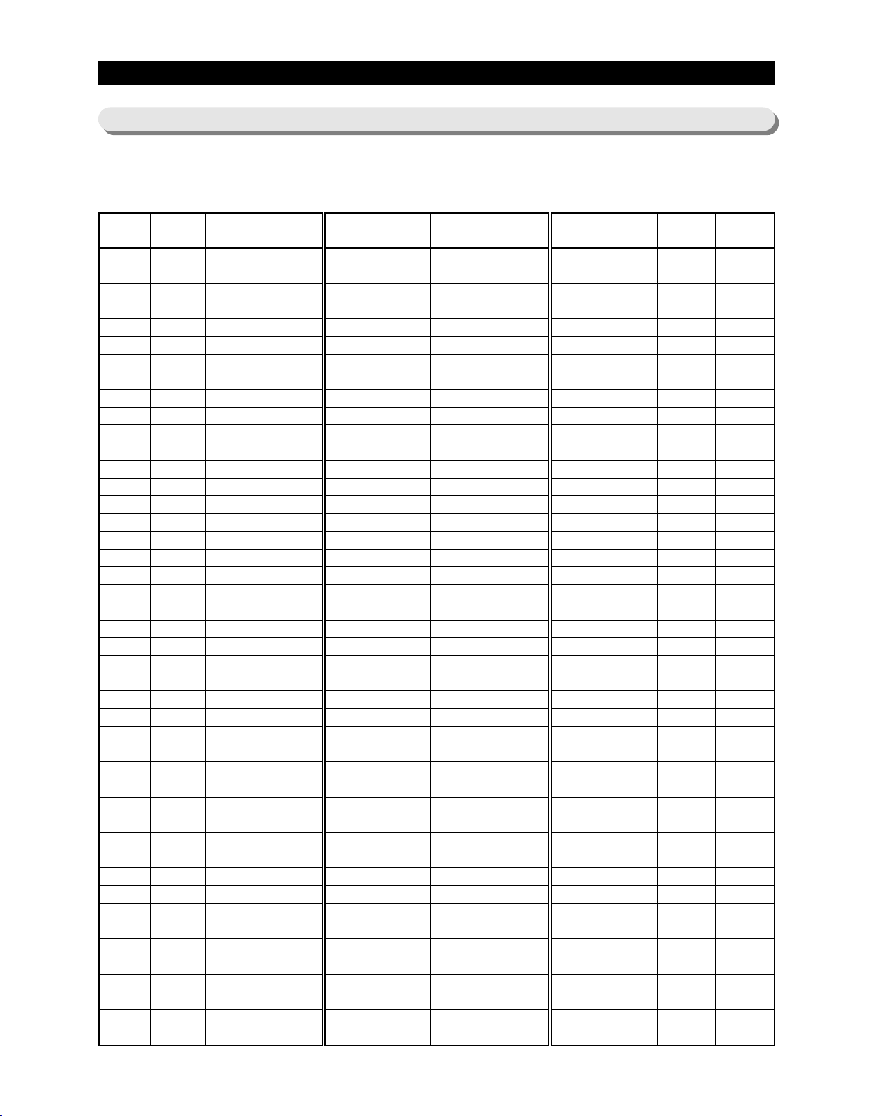
DATA1.Temperature table
Resistance value and MICOM port voltage of sensor according to the temperature
SENSOR CHIP : based on PX41C
℃℉
-50
-49
-48
-47
-46
-45
-44
-43
-42
-41
-40
-39
-38
-37
-36
-35
-34
-33
-32
-31
-30
-29
-28
-27
-26
-25
-24
-23
-22
-21
-20
-19
-18
-17
-16
-15
-14
-13
-12
-11
-10
-9
-8
-7
-6
-58
-56.2
-54.4
-52.6
-50.8
-49
-47.2
-45.4
-43.6
-41.8
-40
-38.2
-36.4
-34.6
-32.8
-31
-29.2
-27.4
-25.6
-23.8
-22
-20.2
-18.4
-16.6
-14.8
-13
-11.2
-9.4
-7.6
-5.8
-4
-2.2
-0.4
1.4
3.2
5
6.8
8.6
10.4
12.2
14
15.8
17.6
19.4
21.2
Voltage
4.694
4.677
4.659
4.641
4.622
4.602
4.581
4.560
4.537
4.514
4.490
4.465
4.439
4.412
4.385
4.356
4.326
4.296
4.264
4.232
4.199
4.165
4.129
4.093
4.056
4.018
3.980
3.940
3.899
3.858
3.816
3.773
3.729
3.685
3.640
3.594
3.548
3.501
3.453
3.405
3.356
3.307
3.258
3.208
3.158
Resistance
153319
144794
136798
129294
122248
115631
109413
103569
98073
92903
88037
83456
79142
75077
71246
67634
64227
61012
57977
55112
52406
49848
47431
45146
42984
40938
39002
37169
35433
33788
32230
30752
29350
28021
26760
25562
24425
23345
22320
21345
20418
19537
18698
17901
17142
℃℉
-5
-4
-3
-2
-1
0
1
2
3
4
5
6
7
8
9
10
11
12
13
14
15
16
17
18
19
20
21
22
23
24
25
26
27
28
29
30
31
32
33
34
35
36
37
38
39
23
24.8
26.6
28.4
30.2
32
33.8
35.6
37.4
39.2
41
42.8
44.6
46.4
48.2
50
51.8
53.6
55.4
57.2
59
60.8
62.6
64.4
66.2
68
69.8
71.6
73.4
75.2
77
78.8
80.6
82.4
84.2
86
87.8
89.6
91.4
93.2
95
96.8
98.6
100.4
102.2
Voltage
3.107
3.057
3.006
2.955
2.904
2.853
2.802
2.751
2.700
2.649
2.599
2.548
2.498
2.449
2.399
2.350
2.301
2.253
2.205
2.158
2.111
2.064
2.019
1.974
1.929
1.885
1.842
1.799
1.757
1.716
1.675
1.636
1.596
1.558
1.520
1.483
1.447
1.412
1.377
1.343
1.309
1.277
1.253
1.213
1.183
Resistance
16419
15731
15076
14452
13857
13290
12749
12233
11741
11271
10823
10395
9986
9596
9223
8867
8526
8200
7888
7590
7305
7032
6771
6521
6281
6052
5832
5621
5419
5225
5039
4861
4690
4526
4369
4218
4072
3933
3799
3670
3547
3428
3344
3204
3098
℃℉
40
41
42
43
44
45
46
47
48
49
50
51
52
53
54
55
56
57
58
59
60
61
62
63
64
65
66
67
68
69
70
71
72
73
74
75
76
77
78
79
80
81
82
83
84
104
105.8
107.6
109.4
111.2
113
114.8
116.6
118.4
120.2
122
123.8
125.6
127.4
129.2
131
132.8
134.6
136.4
138.2
140
141.8
143.6
145.4
147.2
149
150.8
152.6
154.4
156.2
158
159.8
161.6
163.4
165.2
167
168.8
170.6
172.4
174.2
176
177.8
179.6
181.4
183.2
Voltage
1.153
1.124
1.095
1.068
1.040
1.014
0.988
0.963
0.938
0.914
0.891
0.868
0.846
0.824
0.803
0.783
0.762
0.743
0.724
0.706
0.688
0.670
0.653
0.636
0.620
0.604
0.589
0.574
0.560
0.546
0.532
0.519
0.506
0.493
0.481
0.469
0.457
0.446
0.435
0.424
0.414
0.404
0.394
0.384
0.375
Resistance
2997
2899
2805
2714
2627
2543
2462
2384
2309
2237
2167
2100
2036
1973
1913
1855
1799
1745
1693
1642
1594
1547
1502
1458
1416
1375
1335
1297
1260
1225
1190
1157
1125
1093
1063
1034
1006
978
952
926
902
877
854
832
810
57
Page 59
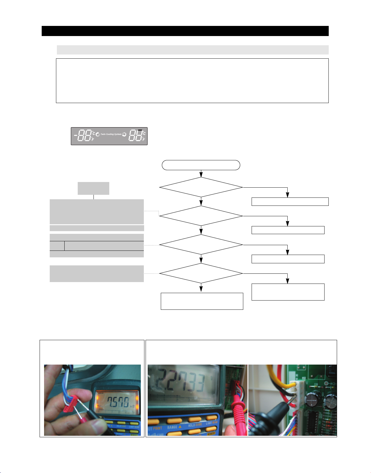
TROUBLESHOOTING
2¢(-17¡) is recommended 38¢(3¡) is recommended
4-2-1. If the trouble is detected by self-diagnosis
- The error of sensor will be displayed on the front of display.
when the error of sensor is detected at initial power ON, the appliance will not operated and display
of abnormal sensor part will blink.
- The appliance will not stop operating when the error of sensor is detected during operation of the
appliance.
But normal freezing might be not operated if the appliance is operated by the emergency operation
mode. You would better to check the appliance according to the self-diagnosis of the manual.
1) If ICE Maker Sensor has trouble
ERROR Code
Start
DATA1.
Temperature table
** Measuring point of resistance value according to
Sensor **
ICE MAKER : CN90#8 ↔#4 measuring resistance value
** 0Ω: Short trouble / ∞Ω: Open trouble
Refer to circuit diagram in the manual
Sensor MICOM/Connector number
ICE
Connector CN90#"4"(White) and
Maker
CN1#"3"(Black) PCB common Ground
Voltage measured between 4.6V ~ 0.6V.
Measuring voltage of IC02 MICOM #30,
CN90#4(White) and CN1#3(Black) from
PCB typical Ground part are similar.
☞ Checking method of ICE Maker Sensor resistance CN90#
"8(Sky-blue) ↔ #4"(White)
- Compare the temperature table after the measure.
☞ Checking method of ICE Maker Sensor resistance
- Measure the voltage of Sensor Check Point #6(IC02 MICOM #30)
on PCB or CN90#4(White) ↔CN1#3(Black)
- Compare the temperature table after the measure.
Measuring voltage of CN90#4(White) ↔ CN1#3(Black) are below.
Is MAIN PCB Connector
NO
CN90 inserted correctly?
YES
Is ICE Maker Sensor
Bad contact of connector/ insert correctly
NO
unit normal?
YES
Is the voltage between
MAIN PCB Connector CN90#"4"(White) and
CN1#"3"(Black) normal?
NO(0.6V > Measurement < 4.6V)
YES
Is input voltage of IC02
NO
Replace the temperature sensor
Recheck the wire connection part
MICOM #30 normal?
YES
No trouble with PCB and temperature sensor.
Check the iced-solder, solder
bridging, disturbed solder.
Recheck the bad contact of the connection.
typical PCB Ground
CN1#3(Black)
58
Page 60
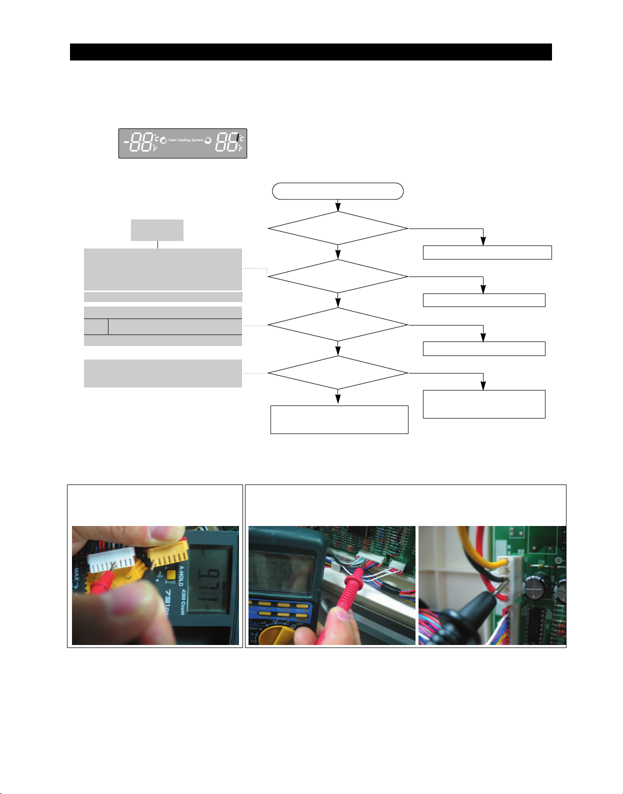
TROUBLESHOOTING
2¢(-17¡) is recommended 38¢(3¡) is recommended
2) If R Sensor has trouble
ERROR Code
Start
DATA1.
Temperature table
** Measuring point of resistance value according to
Sensor **
R : CN30#6 ↔ CN75#1 measuring resistance value
** 0Ω: Short trouble / ∞Ω: Open trouble
Refer to circuit diagram in the manual
Sensor MICOM/Connector number
Connector CN30#6(White) to
R
CN1#3(Black) PCB typical Ground
Voltage measured between 4.6V ~ 0.6V.
Measuring voltage IC01 MICOM #54,
CN30#6(White) and CN1#3(Black)
from PCB typical Ground part are similar.
☞ Checking method of R Sensor resistance
CN30#6(White) ↔ CN75#1(Gray) Compare the
temperature table after the measure.
Is MAIN PCB
Connector CN30 to CN75 inserted
NO
correctly?
YES
Is R Sensor
NO
unit normal?
YES
Is the voltage between
MAIN PCB Connector CN30#6(White) to
CN1#3(Black) normal?
NO(0.6V > Measurement < 4.6V)
YES
Is the input voltage to
NO
IC01 MICOM #54 normal?
YES
No trouble with PCB and temperature sensor.
Recheck the bad contact of the connection.
☞ Checking method of R Sensor resistance
- Measure the voltage of Sensor Check Point #3(IC01 MICOM #54)
on PCB or CN30#6(White) ↔ CN1#3(Black)
- Compare the temperature table after the measure.
Measuring voltage of CN30#6(White)°ÍCN1#3(Black) are below.
Bad contact of connector/ insert correctly
Replace the temperature sensor
Recheck the wire connection part
Check the iced-solder, solder bridging,
disturbed solder.
typical PCB Ground
CN#3(Black)
59
Page 61
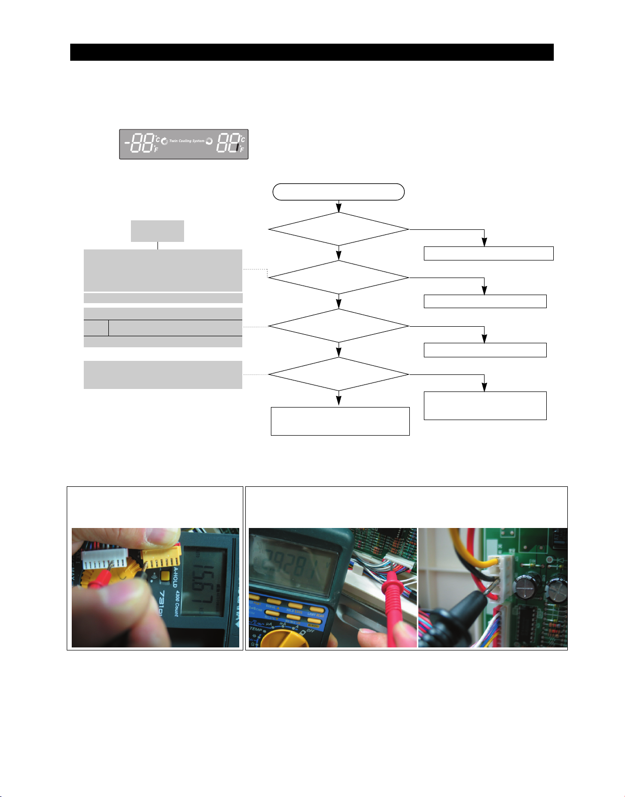
TROUBLESHOOTING
2¢(-17¡) is recommended 38¢(3¡) is recommended
3) If R DEF Sensor has trouble
ERROR Code
Start
Start
DATA1.
Temperature table
** Measuring point of resistance value according to
Sensor **
R-DEF : CN30#7 ↔ CN75#1 measuring
resistance value
** 0Ω: Short trouble / ∞Ω: Open trouble
Refer to circuit diagram in the manual
Sensor MICOM/Connector Number
Connector CN30-"7"(Sky-blue) and
R DEF
CN1-"3"(Black) PCB common Ground
Voltage measured between 4.6V ~ 0.6V.
Measuring voltage of IC01 MICOM #57,
CN30#7(Sky-blue) and CN1#3(Black) from
PCB typical Ground part are similar.
☞ Checking method of R Sensor resistance
CN30#7(Sky-blue) ↔ CN75#1(Gray)
- Compare the temperature table after the
measure.
Is MAIN PCB
NO
Connector CN30 to CN75 inserted
correctly?
YES
YES
Is R DEF Sensor
Bad contact of connector/ insert correctly
NO
unit normal?
YES
YES
Is the input voltage between
MAIN PCB Connector CN30#7(Skyblue)
to CN1#3(Black) normal?
YES
YES
Is the input voltage of IC01
NO(0.6V > Measurement < 4.6V)
NO
Replace the temperature sensor
Recheck the wire connection part
MICOM # 57 normal?
YES
Check the iced-solder, solder bridging,
No trouble with PCB and temperature sensor.
Recheck the bad contact of the connection.
☞ Checking method of R DEF Sensor resistance
- Measure the voltage of Sensor Check Point #4(IC01 MICOM #57) on
PCB or CN30#7Sky-blue)↔CN1#3(Black)
- Compare the temperature table after the measure.
Measuring voltage of CN30#7(Sky-blue) ↔ CN1#3(Black) are below.
disturbed solder.
typical PCB Ground
CN1#3(Black)
60
Page 62
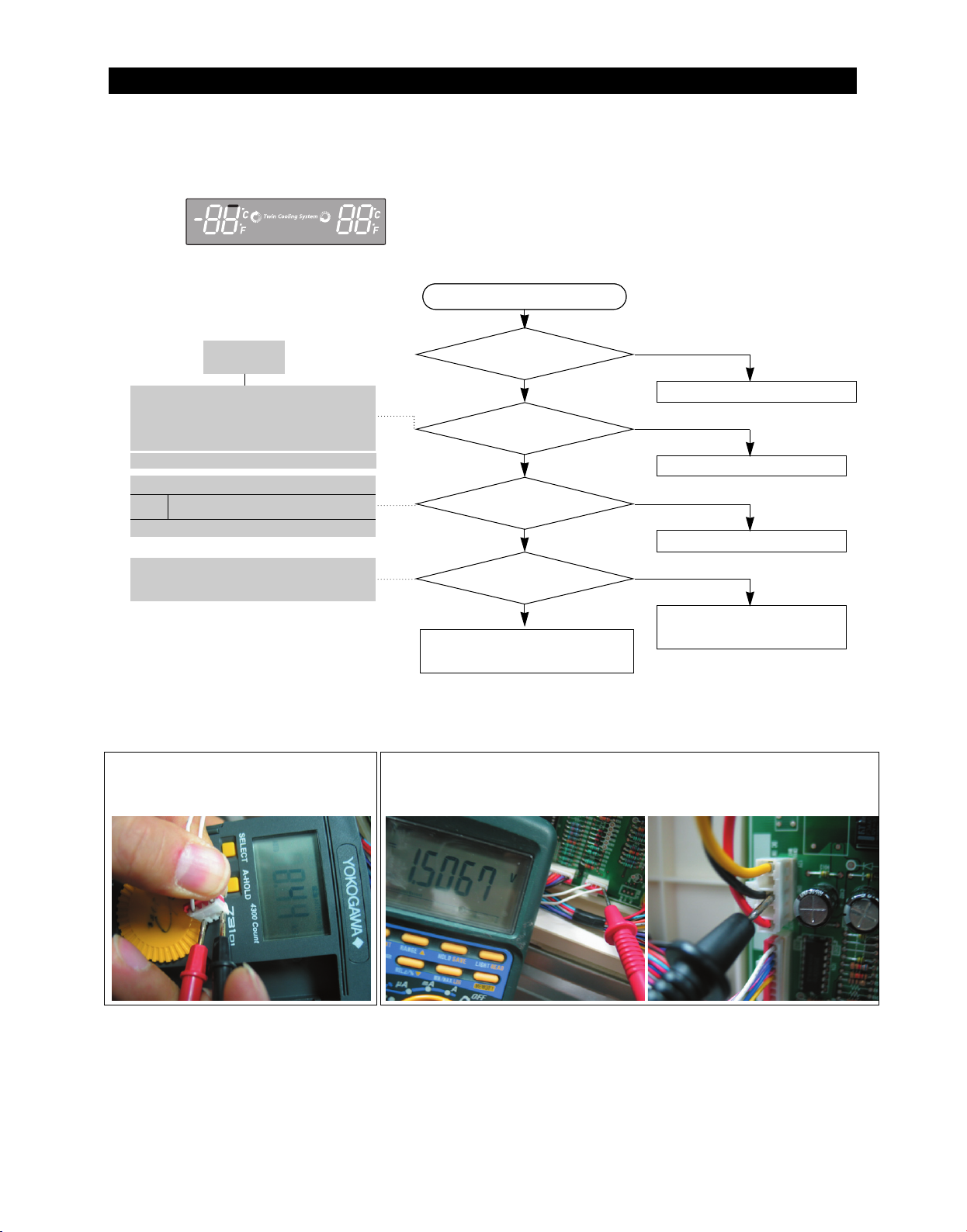
TROUBLESHOOTING
2¢(-17¡) is recommended 38¢(3¡) is recommended
4) If Ambient Sensor has trouble
ERROR Code
Start
Start
DATA1.
Temperature table
** Measuring point of resistance value according to
Sensor **
Ambient : CN32#1 ↔ #4 measuring resistance value
** Placed in the right top table of upper hinge.
** 0Ω: Short trouble / ∞Ω: Open trouble
Refer to circuit diagram in the manual
Sensor MICOM/Connector number
Connector CN32#1(White) to
Ambient
CN1#3(Black) PCB typical Ground
Voltage measured between 4.6V ~ 0.6V.
Measuring voltage of IC01 MICOM #59,
CN32#1(White) and CN1#3(Black) from
PCB typical Ground part are similar.
☞ Checking method of Ambient Sensor resistance
CN32#1(White) ↔ #4(White)
- Compare the temperature table after the
measure
☞ Checking method of Ambient Sensor voltage
- Measure the voltage of Sensor Check Point #7(IC01 MICOM #59)
on PCB or CN32#1(White) ↔ CN1#3(Black)
- Compare the temperature table after the measure
Measuring voltage of CN32#1(White) ↔ CN1#3(Black) are below
Is MAIN PCB
Connector CN32 inserted
NO
correctly?
YES
YES
Is Ambient Sensor
Bad contact of connector/ insert correctly
NO
unit normal?
YES
YES
Is the voltage between
MAIN PCB Connector CN32#1(White)
to CN1#3(Black) normal?
YES
YES
Is the input voltage of
NO(0.6V > Measurement < 4.6V)
NO
Replace the temperature sensor
Recheck the wiring connection
IC01 MICOM #59 normal?
YES
No trouble with PCB and temperature sensor
Check the iced-solder, solder
bridging, disturbed solder
Recheck the bad contact of the connection
typical PCB Ground
CN1#3(Black)
61
Page 63
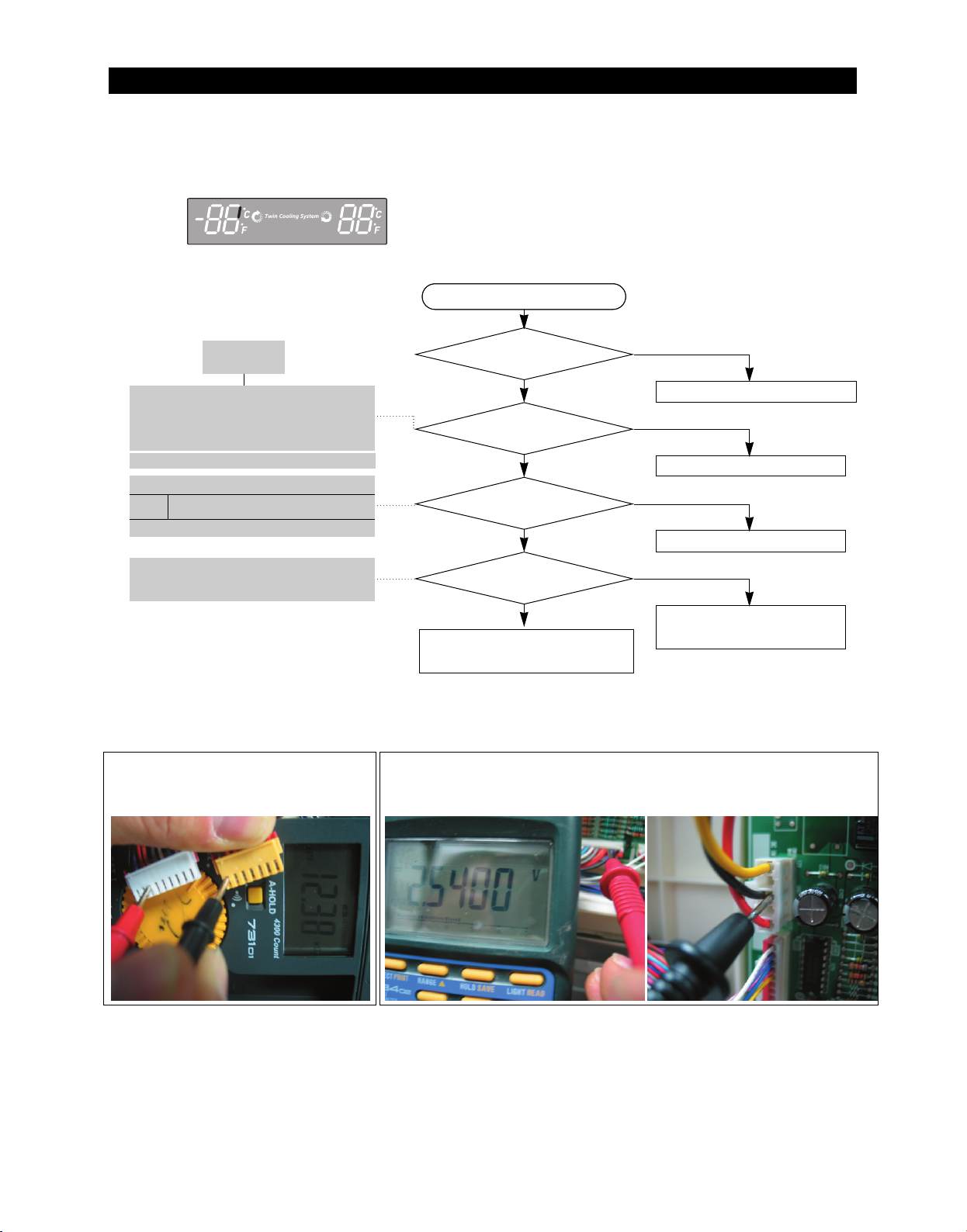
TROUBLESHOOTING
2¢(-17¡) is recommended 38¢(3¡) is recommended
5) If F Sensor has trouble
ERROR Code
Start
Start
DATA1.
Temperature table
** Measuring point of resistance value according to
Sensor **
F : CN30#3 ↔ CN75#1 measuring resistance value
** 0Ω: Short trouble / ∞Ω: Open trouble
Refer to circuit diagram in the manual
Sensor MICOM/Connector number
Connector CN30#3(Red) to
F
CN1#3(Black) PCB typical Ground
Voltage measured between 4.6V ~ 0.6V.
Measuring voltage of IC01 MICOM #52,
CN30#3(Red) and CN1#3(Black) from
PCB typical Ground part are similar.
☞ Checking method of F Sensor resistance
CN30#3(Red) ↔ CN75#1(Gray)
- Compare the temperature table after the measure
☞ Checking method of F Sensor voltage
- Measure the voltage of Sensor Check Point #1(IC01 MICOM #52)
on PCB or CN30#3(Red) ↔ CN1#3(Black)
- Compare the temperature table after the measure
Measuring voltage of CN30#3(Red) ↔ CN1#3(Black) are below.
Are MAIN PCB
Connector CN30 to CN75
NO
inserted correctly?
YES
YES
Is F Sensor
Bad contact of connector/ insert correctly
NO
unit normal?
YES
YES
Is the voltage between
MAIN PCB Connector CN30#3(Red) to
CN1#3(Black) normal?
YES
YES
Is the input voltage of
NO(0.6V > Measurement < 4.6V)
NO
Replace temperature sensor
Recheck the wiring connection
IC01 MICOM #52 normal?
YES
No trouble with PCB and temperature sensor
Check the iced-solder, solder
bridging, disturbed solder
Recheck the bad contact of the connection
typical PCB Ground
CN1#3(Black)
62
Page 64
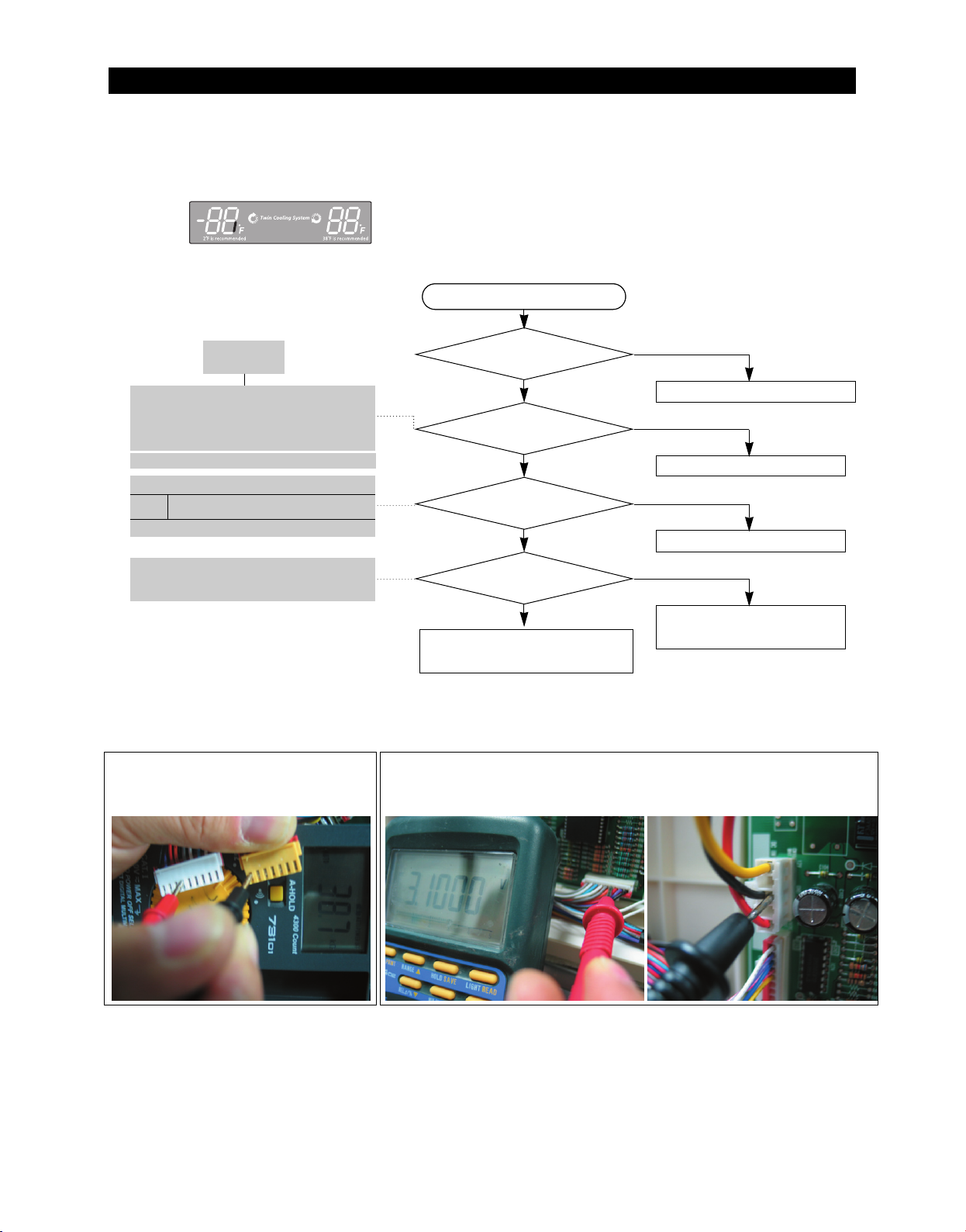
TROUBLESHOOTING
6) If F DEF Sensor has trouble
ERROR Code
Start
Start
DATA1.
Temperature table
** Measuring point of resistance value according to
Sensor **
F-DEF : CN30#4 ↔ CN75#1 measuring resistance
value
** 0Ω: Short trouble / ∞Ω: Open trouble
Refer to circuit diagram in the manual
Sensor MICOM/Connector number
Connector CN30#4(Orange) to
F DEF
CN1#3(Black) PCB typical Ground
Voltage measured between 4.6V ~ 0.6V.
Measuring voltage of IC01 MICOM #53,
CN30#4(Orange) and CN1#3(Black) from
PCB typical Ground part are similar.
☞ Checking method of F DEF Sensor resistance
CN30#4(Orange) ↔ CN75#1(Gray)
- Compare the temperature table after the measure.
☞ Checking method of F DEF Sensor voltage
- Measure the voltage of Sensor Check Point #1(IC01 MICOM
#52) on PCB or CN30#4(Orange) ↔ CN1#3(Black)
- Compare the temperature table after the measure
Measuring voltage of CN30#4(Orange) ↔ CN1#3(Black) are below
Are MAIN PCB
Connector CN30 to
NO
CN75 insert correctly?
YES
YES
Is F DEF Sensor
Bad contact of connector/ insert correctly
NO
unit normal?
YES
YES
Is the voltage between
MAIN PCB Connector CN30#4(Orange)
to CN1#3(Black) normal?
YES
YES
Is the input voltage of
NO(0.6V > Measurement < 4.6V)
NO
Replace temperature sensor
Recheck the wiring connection
IC01 MICOM #53 normal?
YES
No trouble with PCB and temperature sensor.
Check the iced-solder, solder
bridging, disturbed solder
Recheck the bad contact of the connection.
typical PCB Ground
CN1#3(Black)
63
Page 65
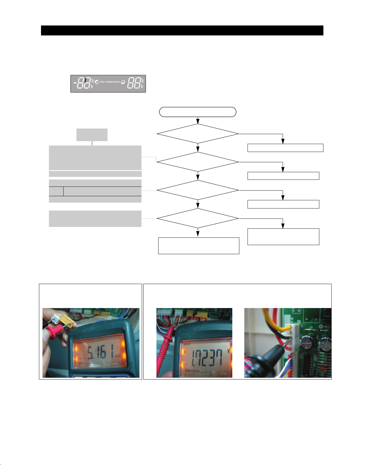
TROUBLESHOOTING
2¢(-17¡) is recommended 38¢(3¡) is recommended
7) If Ice Room Sensor has trouble
ERROR Code
Start
Start
DATA1.
Temperature table
** Measuring point of resistance value according to
Sensor **
Ambient : CN32#3 ↔ CN75#1 Measure the resistance
value
** 0Ω: Short trouble / ∞Ω: Open trouble
Refer to the circuit diagram in this manual
Sensor MICOM/Connector number
Connector CN32-”3”(Orange) and CN1-
Ice Room
☞ Checking Mehod of Ice Room Sensor voltage
CN32-”3”(Orange) ↔ CN75-”1” (Gray)
- Compare with the temperature table after
measurement.
”3”(Black) from typical PCB Ground
Voltage measured between 4.6V ~ 0.6V.
Measuring voltage of IC01 MICOM #51,
CN32-”3”(Orange) and CN1-”3”(Black) from
typical PCB Ground are similar.
☞ Checking Method of Ice Room Sensor Voltage
- Measure the voltage of sensor checking point #8(IC01 MICOM #51) on
PCB or CN32-”3” (Orange) ↔ CN1-”3”(Black)
- Compare with the temperature table after measurement.
Measured voltage of CN32-”3” (Orange) ↔ CN1-”3” (Black) are below
Is MAIN PCB
Connector CN32 inserted correctly?
YES
YES
Is Ice Room Sensor
NO
Bad contact of connector/ insert correctly
NO
unit normal?
YES
YES
Is the voltage between
MAIN PCB Connector CN32-”3”(Orange)
to CN1-”3”(Black) normal?
YES
YES
Is the input voltage of
NO(0.6V > Measurement < 4.6V)
NO
Replace temperature sensor
Check the wiring connection
IC01 MICOM #51 normal?
YES
No trouble with PCB and temperature sensor.
Check the iced-solder, solder
bridging, disturbed solder
Check the bad connections.
Typical PCB Ground CN1-”3”
(Black)
64
Page 66
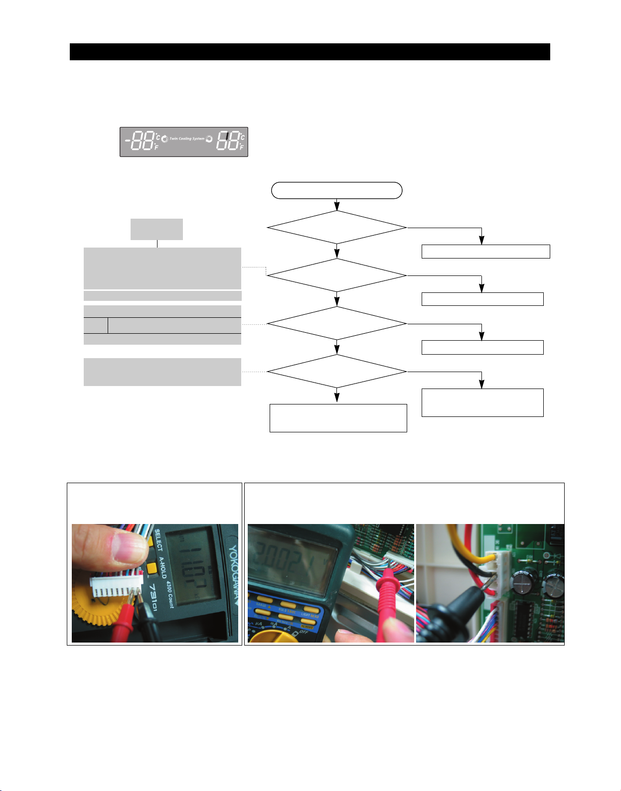
TROUBLESHOOTING
2¢(-17¡) is recommended 38¢(3¡) is recommended
8) If Pantry Sensor has trouble
ERROR Code
Start
Start
DATA1.
Temperature table
** Measuring point of resistance value according to
Sensor **
Pantry : CN30#8 ↔#9 measuring resistance value
** 0Ω: Short trouble / ∞Ω: Open trouble
Refer to circuit diagram in the manual
Sensor MICOM/Connector number
Connector CN30#8(White-black) to
Pantry
CN1#3(Black) PCB typical Ground
Voltage measured between 4.6V ~ 0.6V.
Measuring voltage of IC01 MICOM #58,
CN30#8(White-black) and CN1#3(Black)
from PCB typical Ground part are similar.
☞ Checking method of Pantry Sensor resistance
CN30#8(White-black) ↔ #9(Gray)
- Compare the temperature table after the measure
☞ Checking method of Pantry Sensor voltage
- Measuring voltage of Sensor Check Point #5(IC01 MICOM #58) on
PCB or CN30#8(White-black) ↔ CN1#3(Black)
- Compare the temperature table after the measure
Measuring voltage of CN30#8(white-black)↔CN1#3(Black) are below
Is MAIN PCB
Connector CN30 insert
NO
correctly?
YES
YES
Is Pantry Sensor
Bad contact of connector/ insert correctly
NO
normal?
YES
YES
Is the voltage between
MAIN PCB Connector CN30#8(Whiteblack)
to CN1#3(Black) normal?
YES
YES
Is the input voltage of IC01
NO(0.6V > Measurement < 4.6V)
NO
Replace temperature sensor
Recheck the wiring connection
MICOM Pin# 58 normal?
YES
No trouble with PCB and temperature sensor.
Check the iced-solder, solder
bridging, disturbed solder
Recheck the bad contact of the connection.
typical PCB Ground
CN1#3(Black)
65
Page 67
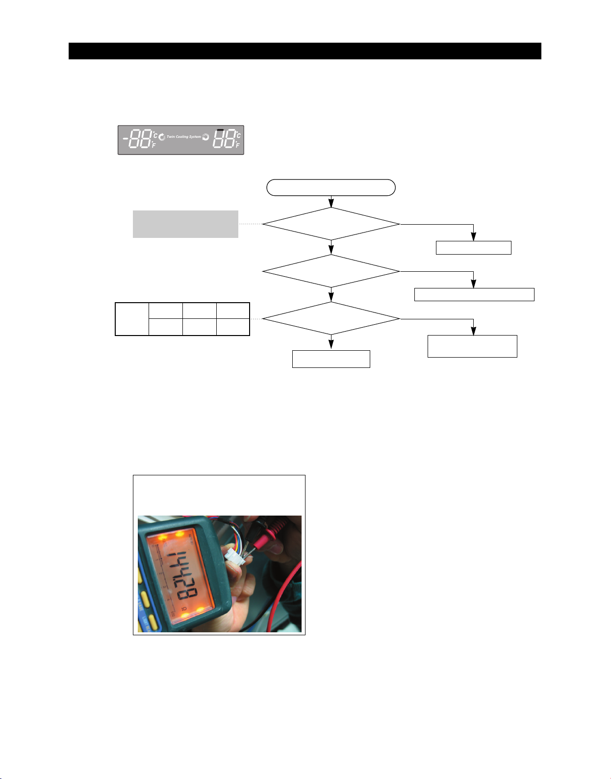
TROUBLESHOOTING
2¢(-17¡) is recommended 38¢(3¡) is recommended
9) If Pantry Room Damper Heater has trouble
ERROR Code
Start
Start
Measure the resistance
between ①-② after
CN90 connector open 145ohm ± 7%
MICOM
#37
condition
Initial
power On
4.0V ~
4.5V
Damper
heater off
4.0V ~
4.5V
Damper
heater On
0V
☞ Checking method of Pantry Room Damper
resistance CN91#1(Black) ↔ #2(Brown)
** ∞Ω: Open(wire disconnection, heater
disconnection) trouble 0Ω: Short trouble
Is Damper Heater
normal?(about145ohm)
YES
YES
Is MAIN PCB connector
(CN91) inserted correctly?
YES
YES
Is the input voltage of
IC02 MICOM #37 normal?
YES
YES
Normal(recheck)
NO
Replace Damper
NO
Bad contact of connector/ insert correctly
NO
1) Recheck the wire
2) Replace PCB MAIN
66
Page 68
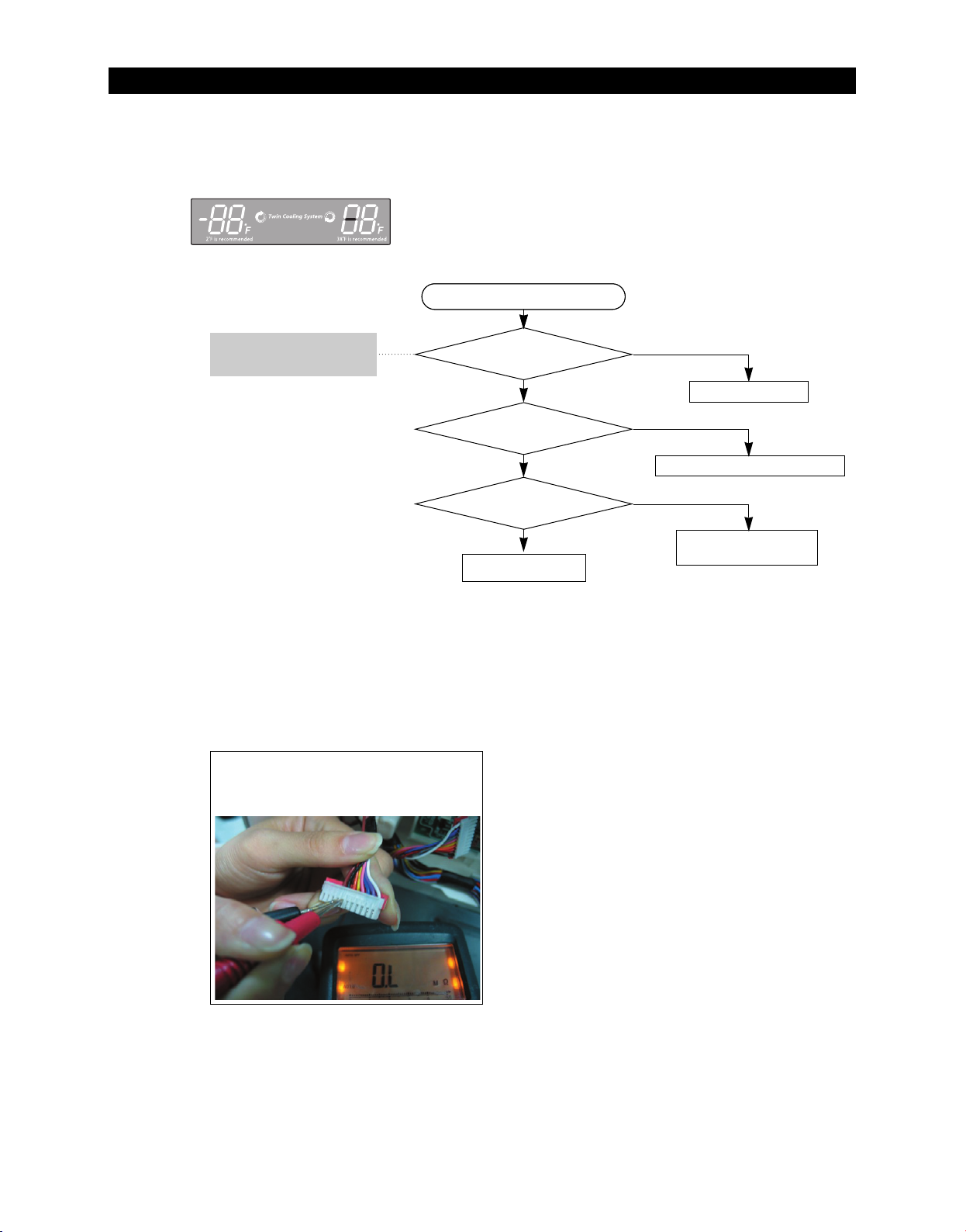
TROUBLESHOOTING
10) If Tank Water Heater has trouble
ERROR Code
Start
Start
Measure the resistance
between ④-⑤ after
CN78 connector open 48ohm ± 7%
☞ Checking method of Tank Water Heater
resistance CN78#5(Black) ↔ #4(Brown)
** ∞Ω: Open(wire disconnection, heater
disconnection) trouble 0Ω: Short trouble
Is Tank Water Heater
normal?(about48ohm)
YES
YES
Is MAIN PCB connector
(CN78) inserted correctly?
YES
YES
Is the input voltage of
IC01 MICOM #8 normal?
YES
YES
Normal(recheck)
NO
Replace Tank Water Heater
NO
Bad contact of connector/ insert correctly
NO
1) Recheck the wire
2) Replace PCB MAIN
67
Page 69
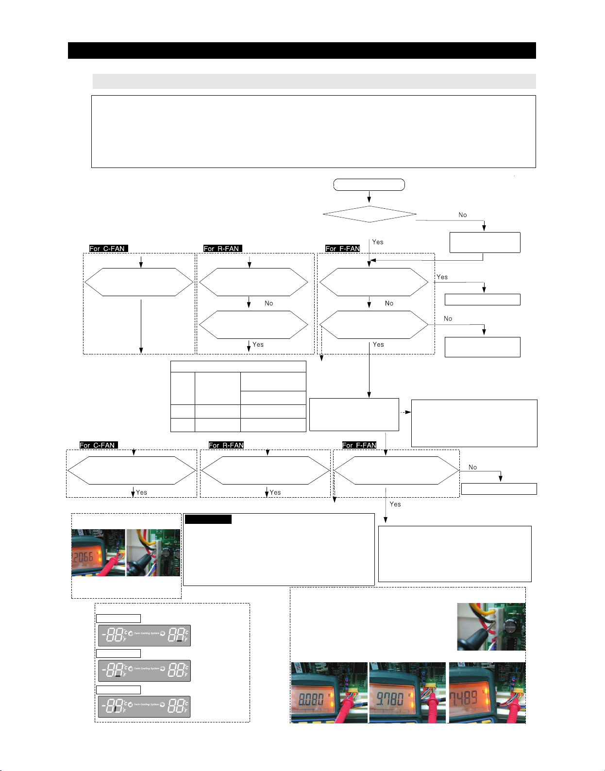
TROUBLESHOOTING
2¢(-17¡) is recommended 38¢(3¡) is recommended
2¢(-17¡) is recommended 38¢(3¡) is recommended
2¢(-17¡) is recommended 38¢(3¡) is recommended
4-2-2. If FAN does not operate
- The refrigerator of this model has BLDC FAN motor. BLDC motor is driven by DC 7~12V.
- On the normal condition of COMP ON, it operates together with F-FAN motor.
If door is opened and closed once at a high ambient temperature, it will be operated after 1 minute
delay.
Therefore, you are advised not to taken it for an error.
-. If there is a trouble, you should select the self-diagnostic function to check the trouble before power off.
Start
Is COMPRESSOR ON ?
Execute manual
operation
Is the voltage between MAIN
PCB CN1#3 (Black) and CN75#4(Sky
-blue) around DC7~12V?
Door
Close
Open
Does DC7~12V alternate with below
DC 2V between MAIN PCB CN1#3(Black)
and CN75#4(Sky-blue)
F FAN pulse voltage
CN75#5(Black)
The voltage measured around 2~3V
with multi-meter though the voltage is
very weak because of pulse signal
☞ Display for checking the self-diagnostic function
R FAN ERROR
typical PCB Ground
CN10#3(Black)
Is the voltage between MAIN
PCB CN1#3 (Black) and CN75#3
(Orange) around DC7~12V?
Is the voltage between MAIN
PCB CN1#3 (Black) and CN30#2
(Purple) around 0V?
Is the voltage between MAIN
PCB CN1#3 (Black) and CN75#2
(Yellow) around DC7~12V?
Is the voltage between MAIN
PCB CN1#3 (Black) and CN30#1
(Black) around 5V?
Door & MICOM State
F
MICOM
(#50)
5V(High)
0V(Low)
Does DC7~12V alternate with below
DC 2V between MAIN PCB CN1#3(Black)
Reference
CN75-5(F),6(R),7(C)will generate the pulse signal when motor rotates.
These signals will be inputted into MICOM.
Unless signals are not inputted during motor operating, will be ON 10
seconds after fan Off. But if signals are not still entered, the above operation
will restart four times more.
If signals are not entered continuously, the motor will be restarted after 10
seconds.
This function is effective when the normal operation of motor would be
restrained by foreign matters such as ice.
R MICOM(#3)
Right and Left
0V(Low)
5V(High)
and CN75#3(Orange)
Power ON with 5 minutes
delay after power OFF.
For preventing the over
load of compressor)
Does DC7~12V alternate with
below DC 2V between MAIN PCB
CN1#3(Black) and CN75-#2(Yellow)
☞Checking method of R,F,C FAN Motor voltage
The voltage between PCB typical Ground CN1-"3"(Black) and
R FAN ; CN75#2(Yellow) shall be less than DC 7~12V.
F FAN ; CN75#3(Orange) shall be less than DC 7~12V.
C FAN ; CN75#4(Sky-blue) shall be less than DC 7~12V.
- Recheck if resistance values are different after measuring.
FAN work normally
Repair the connection
of Door switch
In initial power to appliance, the compressor
and fans of fresh food/ freezer, compressor
fan operate. If freezer temperature is
sensed of 41℉by momentary power
failure, fans will operate after 5 minutes.
Replace MAIN PCB
◆ Expected causes
①Check that if FAN-MOTOR has failure
itself.
②Check that if wiring connection has bad
contact.
③ Check the input of the fan motor rotation
pulse when motor fan operates.
typical PCB Ground
CN1#3(Black)
F FAN ERROR
C FAN ERROR
1) R-FAN 2) F-FAN 3) C-FAN
68
Page 70
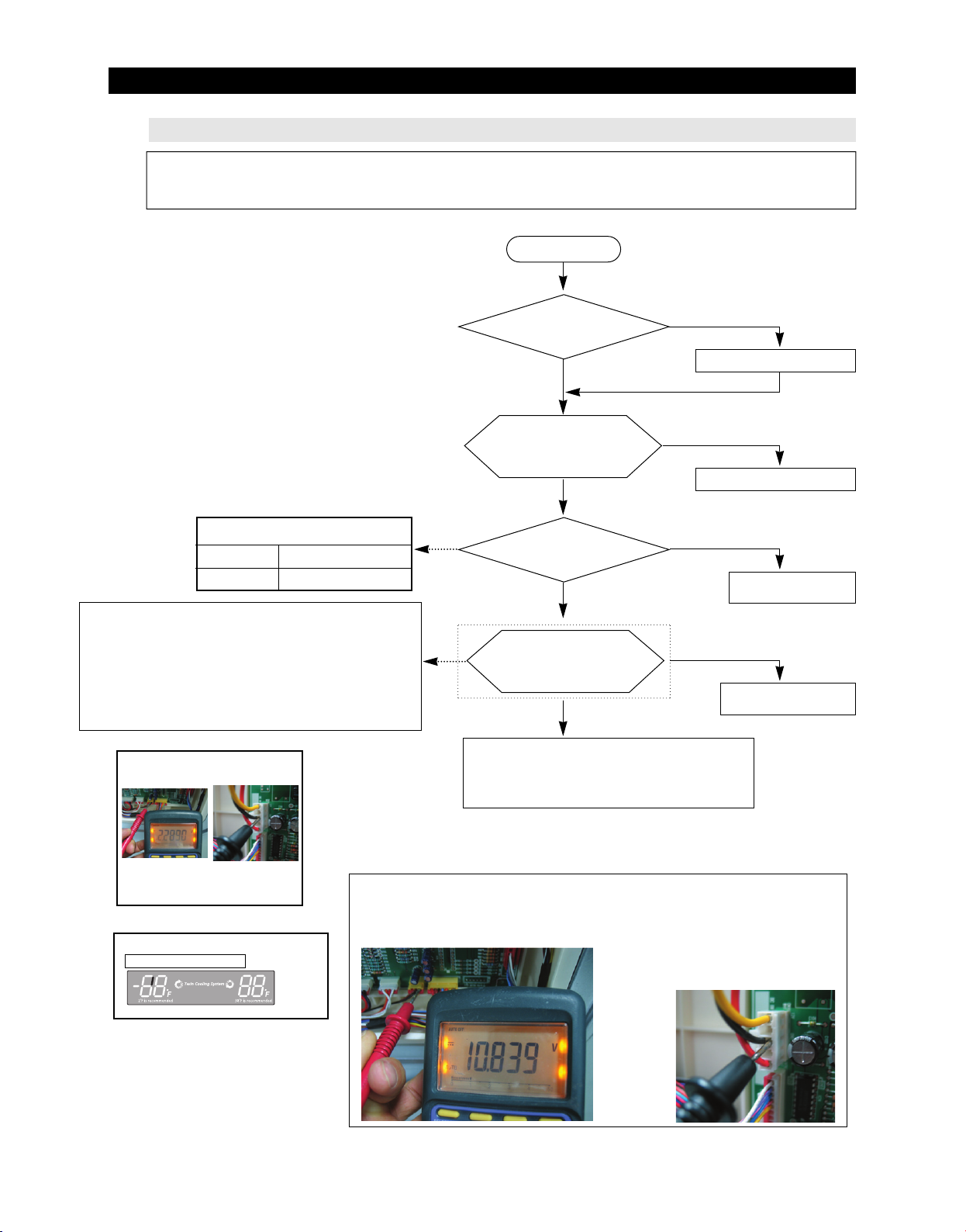
TROUBLESHOOTING
4-2-3. If ICE Room Fan does not operate
- This refrigerator has BLDC FAN motor. BLDC motor is driven by DC7~12V.
- When COMP ON, normally operates with F-FAN motor.
- If there is any trouble, you should select the self-diagnostic function to check the trouble before power off.
Start
Ice Room control temperature
Ice ON
Ice OFF
Reference
CN76 #2 will generate the pulse signal when motor rotates.
These signals will be input into MICOM.
Unless signals are not input during motor operating, will be ON
10seconds after fan OFF. But if signals are not still taken, the
above operation will be retried four times more. If signals are not
taken continuously, the motor will be restarted after 10 minutes.
This function is against the case that motor movement would be
restrained by foreign matters like ice.
FAN pulse voltage
CN76-”2”(Brown)
Typical PCB Ground
CN1-”3”(Black)
8.6℉(-13℃)
26.6℉(-3℃)
Is COMPRESSOR ON ?
Yes
Is the voltage between
MAIN PCB CN1-”3”
No
Execute manual operation
Yes
(Black) and CN76-”1”
(Black) around DC7~12V?
No
Is the Ice Room
temperature suitable for
FAN works normally
No
the Fan working?
Yes
Does DC7~12V alternate
with below DC2V between MAIN PCB CN1-
Operation
temperature/ready
No
”3”(Black) and CN75-”2”(Yellow)?
Yes
Replace MAIN PCB
◆ Predicted Cause
① FAN-MOTOR troubles itself
② Bad wiring connections.
③ Wrong Input of the fan motor rotation pulse
The voltage is variable due to pulse
signal but measured about 2~3V with the
Multi-Meter.
☞ Display for checking the self-diagnostic function
Ice Room FAN ERROR
☞ Checking method of Ice Room FAN Motor Voltage with the voltage between typical
PCB Ground CN1-”3”(Black) and Ice Room FAN ; CN76-”1”(Black) shall be less
than DC 6~12V.
- Additional check if resistance values are different after measurement.
1) Ice Room - FAN
Typical PCB Ground
CN1-”3”(Black)
69
Page 71
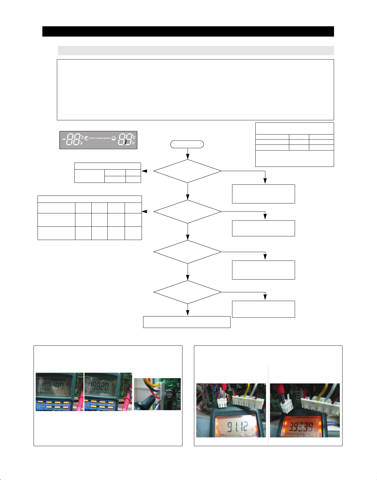
TROUBLESHOOTING
2¢(-17¡) is recommended 38¢(3¡) is recommended
4-2-4. If Ice Maker does not operate
1. Water is automatically supplied to the Ice Maker by temperature & time and Ice Maker Dispenses cubed or
crushed ice.
2. Power is applied to the one end of wires. Be careful when disassembling and shall refer to its exploded diagram
in any case.
3. Ice Maker operation shall be checked after pressing the Ice Maker testing switch.
(Freezer Ice Maker) It is not possible to check when the power is disengaged.
4. We recommend that TWO PEOPLE check the PCB and Ice Maker because hey are located at front and rear
side each.
5. Be careful! The Ice Maker Heater can cause personal injury like burn.
Displays ERROR Code
MICOM(IC02) Operation Status
#29
(Test Switch)
MICOM(IC02) Operation Status
Ready Rotation
#27
(Blade Ice Scoop)
#28
(Guide Ice Full)
0V 4.9V 4.9V 0V
0V 0V 4.9V 0V
Operation5VReady
0V
Before
Returning
Complete
Start
Does Ice Maker
rotate when pressing the Ice Maker
testing switch(over 1.5 sec)?
Yes
Is the input voltage of IC02
MICOM #27, 28 normal?
Yes
Operating Condition when motor rotates
Operating Status of Micom(IC02)
Motor Load (#10)
Heater Load (#9)
Heater operates differently according to
the conditions.
No
1) Replace the Ice Maker Kit
2) Check/Replace the Main PCB
Test Mode operation will be 30 sec.
input signal
(Micom IC02 Pin #29 - “0V”)
No
1) Check the wiring connections.
2) Replace Ice Maker Kit
3) Replace MAIN PCB
Ready
0V
0V
Operation
5V
5V
Is the water supplied in 6
minutes (After sensing ice bucket
Is the Ice Maker Sensor unit normal?
No trouble with PCB and temperature sensor,
Check the bad wiring connections.
☞ Checking Method of ICE Maker Voltage
With typical PCB Ground CN1-”3”(Black) and
1) Test Switch operation (press selected) : CN90-”5” (Gray) shall be DC 0V.
Test Switch ready ; CN90-”5” (Gray) shall be less than DC 5V.
1)Test Switch operating 1)Test Switch ready
☞ Checking Method of ICE Maker Voltage
With typical PCB Ground CN1-”3”(Black) and
2) IC02 MICOM #27 voltage ; Ready(0V) → Rotate (4.9V) → Before
complete(4.9V) → Return(0V)
* MICOM #27 voltage is same as Connector CN90-”7”(Purple)
3) IC02 MICOM #28 voltage ; Ready(0V) → Rotate (0V) → Before
complete(4.9V) → Return(0V)
* MICOM #28 voltage is same as Connector CN90-”6”(Blue)
typical PCB Ground
CN1-"3"(Black)
No
fully)?
Yes
1) Replace the Water Valve
* Refer to the operation
condition of Water Valve
2) Replace the Main PCB
No
Yes
☞ Check the ICE Maker Heater & Motor Resistance
Resistance value can be changed according to the Voltage and
Perfermance changes.
1) Measuring the Ice Maker Heater
resistance values
CN70-”1” (Red) & CN72-”3” (White)
Resistance value : 91(364)Ohm± 7% Resistance value : 3.93(11.76)KOhm± 7%
1) Repair the Ice Maker Sensor
* Refer to the solution “If Ice
Maker Sensor has trouble”
2) Measuring the Ice Maker Motor
resistance values
CN70-”1” (Red) & CN72-”1” (Brown)
70
Page 72
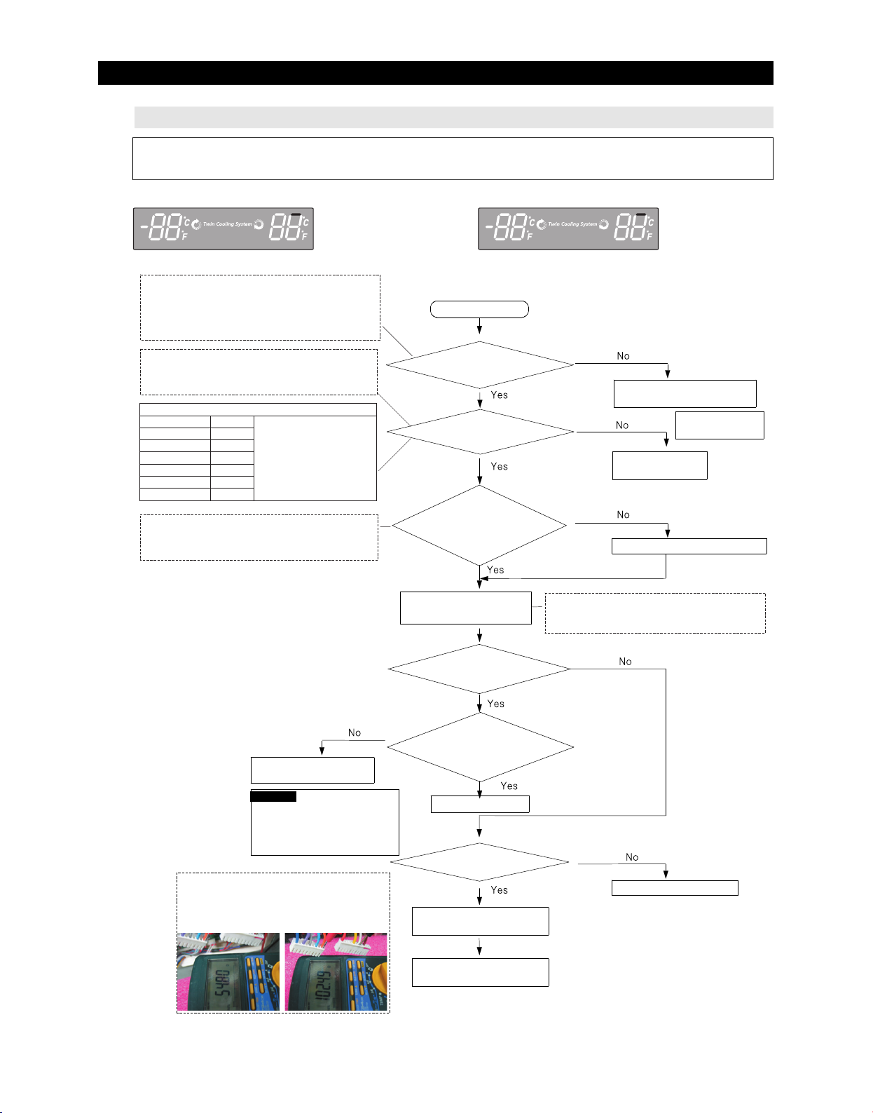
TROUBLESHOOTING
2¢(-17¡) is recommended 38¢(3¡) is recommended
2¢(-17¡) is recommended 38¢(3¡) is recommended
4-2-5. If defrost does not operate (F,R DEF Heater)
- If defrost has trouble, select the self-diagnostic function to detect the error of defrost heater before
Power Off. (Check the function with refer to the self-diagnostic function)
R DEF ERROR
**Measuring point of resistance value according to heater**
F-DEF : CN70#9(Brown) ↔ CN71#9(Orange) measuring
resistance value(55(216) ohm ± 7%)
R-DEF(Ice Pipe parallel) : CN70#7(White)↔N71#9(Orange)
measuring resistance value(105(441) ohm ± 7%)
** 0Ω: Short trouble / ∞Ω: Open(bimetal, heater) trouble
**Measuring point of resistance value according to sensor **
F-DEF : CN30#4 ↔ CN75#1 measuring resistance value
R-DEF : CN30#7 ↔ CN75#1 measuring resistance value
** 0Ω: Short trouble / ∞Ω: Open trouble
Resistance value of sensor according to temperature
86℉(30℃)
68℉(20℃)
50℉(10℃)
32℉(0℃)
14℉(-10℃)
-4℉(-20℃)
-22℉(-30℃)
**Measuring point of resistance value according to sensor **
F-DEF : CN30#4 ↔ CN75#1 measuring resistance value
R-DEF : CN30#7 ↔ CN75#1 measuring resistance value
** 0V: Short trouble / 5V: Open trouble
4.22㏀
6.05㏀
8.87㏀
13.29㏀
20.42㏀
32.23㏀
52.41㏀
If you need the
temperature with detail,
refer to DATA1.
temperature
table
Start
Are the all deforst
heater normal?
Is defrost sensor by
self-diagnostic normal?
Is the temperature of
defrost sensor lower
than 53.6℉(12°C)?
Manual defrosting of fresh food
and freezer compartments
operate simultaneously.
F DEF ERROR
Check the bimetal, heater
disconnection, wiring connection etc.
Refer to self-diagnostic
function in the manual
Replace the
applicable sensor
manual operation for a certain time
If Energy Saver + Fridge Key are pressed
simultaneously for 8 seconds and then select any key,
3rd test mode(manual defrosting) will be operated.
Recheck the applicable
sensor.
Reference If defrost sensor
temperatures of fresh food and
freezer compartments are higher
than 50℉(10℃), 53.6℉(12℃) by
the heating from heater, heating
would be finished and will return
to cooling operation after a pause.
☞Checking method of F,R DEF Heater resistance value
F FEF ; CN70#9(Brown) ↔ CN71#9(Orange)
R FEF ; CN70#7(White) ↔ CN71#9(Orange)
- Recheck if resistance values are different after the test
1) F DEF Heater 2) R DEF Heater
Is power applied to
each defrost heaters?
Does the system return
to cooling operation after
heating for specified time?
Normal
Is connection terminal of
MAIN PCB part normal?
Repair connection terminal
Check bimetal, heater itself,
disconnection etc.
Replace failure Relay or
replace PCB ASS'Y
71
Page 73
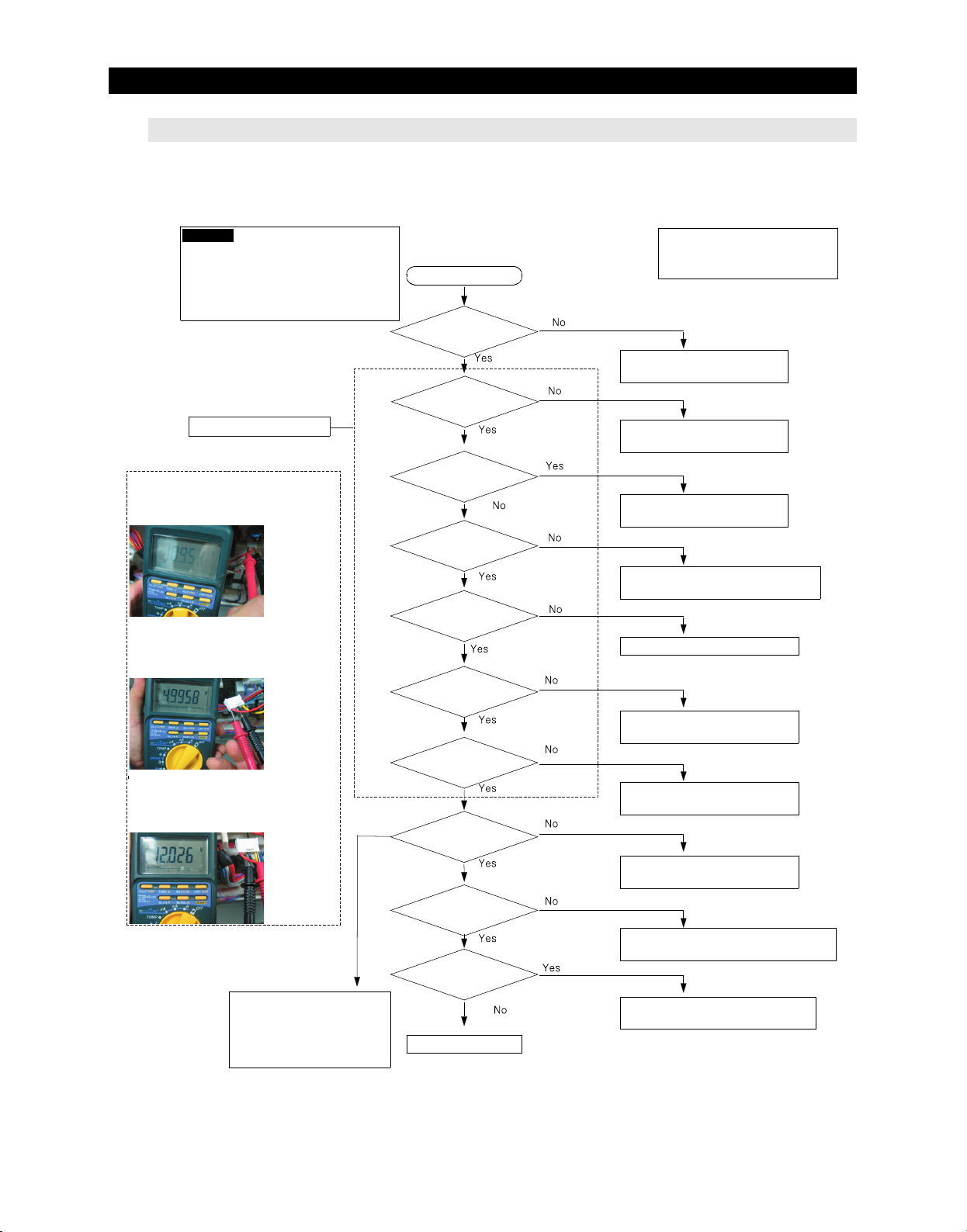
TROUBLESHOOTING
4-2-6. If Power is not supplied
Caution
At the power of main PCB, the
AC115(230)V power and a highvoltage over DC 170(325)V are
occurred.Please take care of
yourself on repair and measurement.
Check in SMPS PBA
☞ Checking method of SMPS voltage CN1
input ; CN1#1(Red) ↔ #3(Black) AC voltage
☞ Checking method of SMPS 2nd output
voltage CN2 input ; CN2#1(Red) ↔
#3(Black) →same as C19 terminals..
DC 5V ± 0.3V
☞ Checking method of SMPS 2nd output
voltage CN2 input ; CN2#5(Yellow) ↔
#3(Black) →same as C16 terminals.
DC 12V ± 0.6V
Start
Is plug connected in?
Is power 115(230)V
both terminals of SMPS
PCB CN1?
Is fuse on the SMPS
PCB down?
Is DC170(325)V
applied between both
terminals of BD1+,-
Is DC5.8V
applied between TOP
switch 246Y C to S?
Is 12V
applied between both
terminals of C16?
Is 5V
applied between both
terminals of C19?
Does Panel PCB
operate normally?
- Refer to function and
reference parts in the manual
when check the MAIN PCB
Connect plug again,
check the plug loosening
Check the assembly and wire
connection
1) Replace FUSE AC 250V 2.0A
2) Replace SMPS assembly
1) Check PCB PATTERN and replace BD1
2) Replace PCB ASS'Y
Replace PCB ASS'Y
1) Replace U4 (D10LC20U)
2) Replace PCB ASS'Y
1) Replace REG1 (KA7805)
2) Replace PCB ASS'Y
1) Check assembly wire and repair
2) Replace Panel PCB
- Check MAIN PCB connection
- Check the connections
between cabinet to door
- Check the connections
between door to panel PCB
Is normal load such
as Relay?
Is there any PCB
soldering, short,
breakage?
Normal(Recheck)
72
1) Check the contact of lead wire
2) Replace the applicable relay / PCB MAIN
1) Solder again
2) Replace PCB MAIN
Page 74
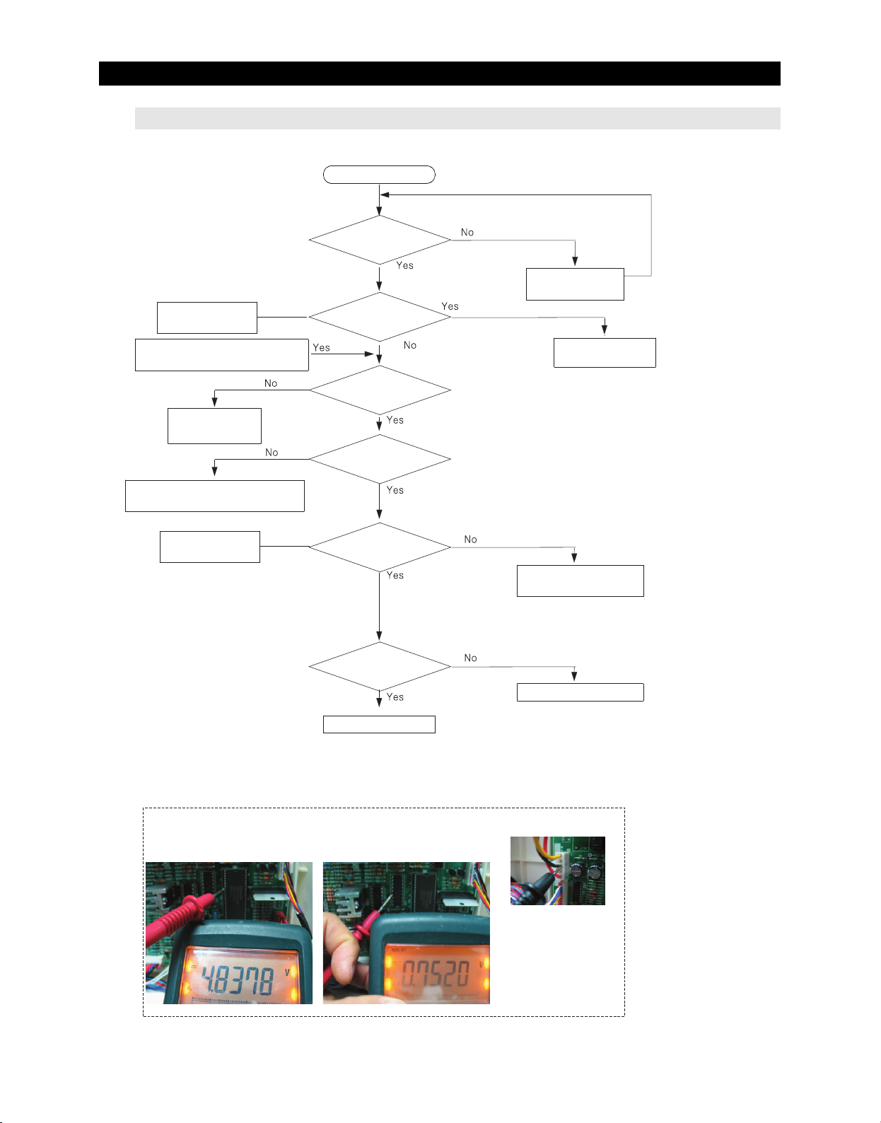
TROUBLESHOOTING
4-2-7. If compressor does not operate
Refer to test function
in the manual
Start
Did 5 mins pass
after Compressor
OFF ?
Check after
5 minutes
Does compressor work
with manual operation?
Did buzzer of manual operation sound?
(Check certainly after manual operation)
1) Replace MICOM
2) Replace PCB
1) Replace IC72 Driver IC(TD62083AP)
2) Replace PCB
Refer to circuit diagram
in the manual
normal
Is IC02 MICOM #8
High?(5V)
Is IC72 #15 about
0.8V?
Is CN71 connector
normal?
Check bad contact of
connector
Is COMP ASS'Y
normal?
Replace COMP ASS'Y
Normal (recheck)
☞Checking method of voltage PCB typical
Ground CN1#3(Black) and
1) IC02 MICOM #8 ; voltage High(5V ±0.5V)
IC02 MICOM #8, COMP operating
☞Checking method of voltage
PCB typical Ground CN1#3(Black) and
1) IC72 #15 : Voltage Low(0V)
73
typical PCB Ground
CN1#3(Black)
Page 75
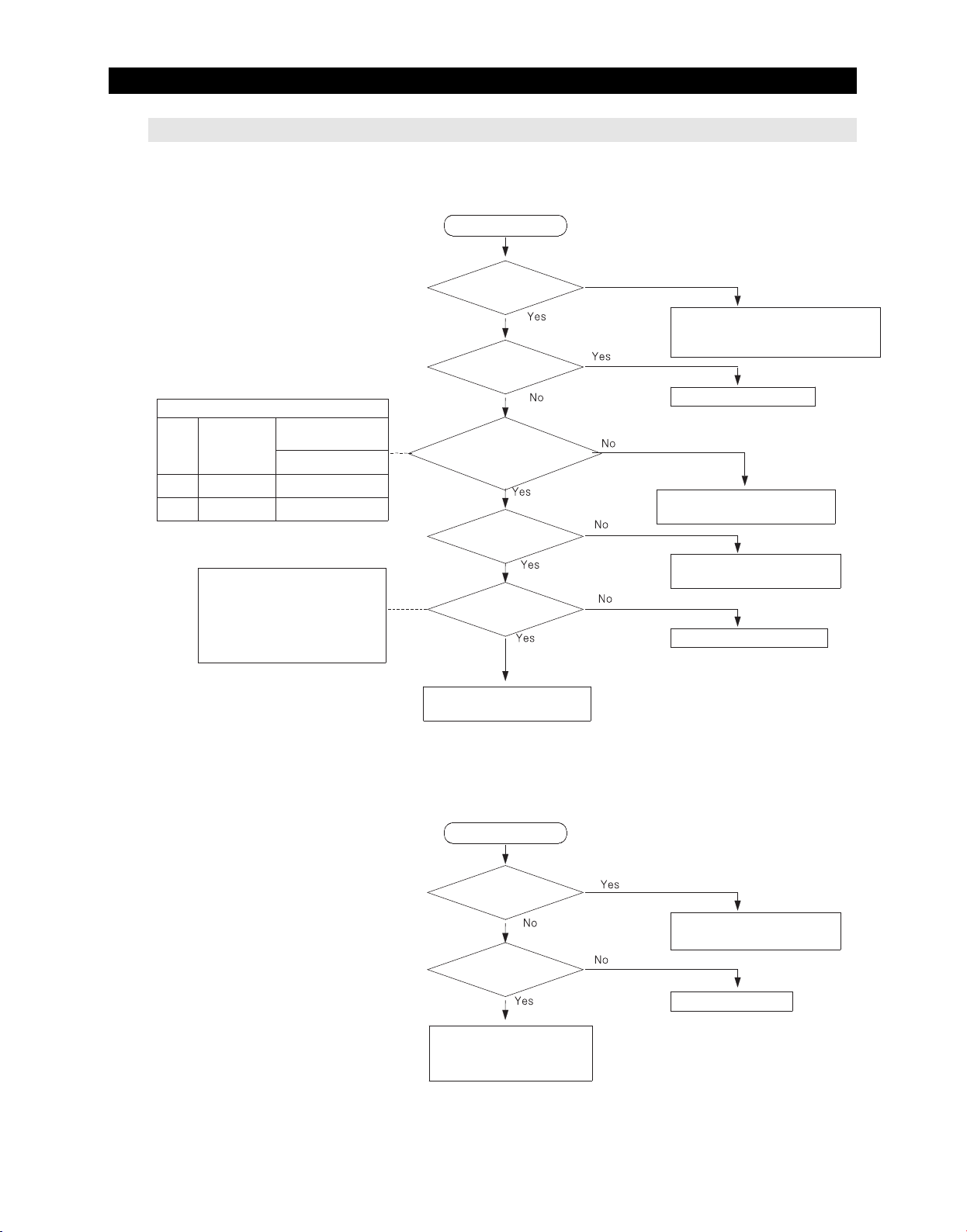
TROUBLESHOOTING
4-2-8. When alarm sound continuous without stop(related with buzzer sound)
① If 'ding-dong' sounds continuously
Start
Door & MICOM State
DoorFMICOM
(#50)
Close
5V(High)
Open
0V(Low)
Separate the door switch and check if
the measured value of unit is
changed from 0Ω to∞Ω according
to switch ON/OFF.
* FF Door Switch is magnetic switch .
(it can be operated when door
magnet is combined with)
R MICOM(#3)
Right and Left
0V(Low)
5V(High)
Is door closed
completely?
Is water penetrated
into the door switch?
Is the input
voltage of main #50 and #3
changed at door-open,
door-close?
Is the connector(CN30)
inserted correctly?
Is the door switch unit
normal?
Recheck MAIN PCB and
door switch
Door is ajar
Remove causes after comprehending
the conditions of interference by door
gasket, food etc.
Replace Door S/W
Repair wire connection and
Door S/W
Connector is not inserted,
Repair bad contact
Replace Door S/W
② If 'beep-beep' sounds continuously
Start
Is manual operation
/defrost selected?
Does buzzer sounds
when power On again?
Check if there is any short parts
due to foreign matters and the
test jumper part in the mainPCB.
74
Enforce the cancelation the
manual operation/ defrost function
or power On after power Off
MAIN PCB normal
Page 76
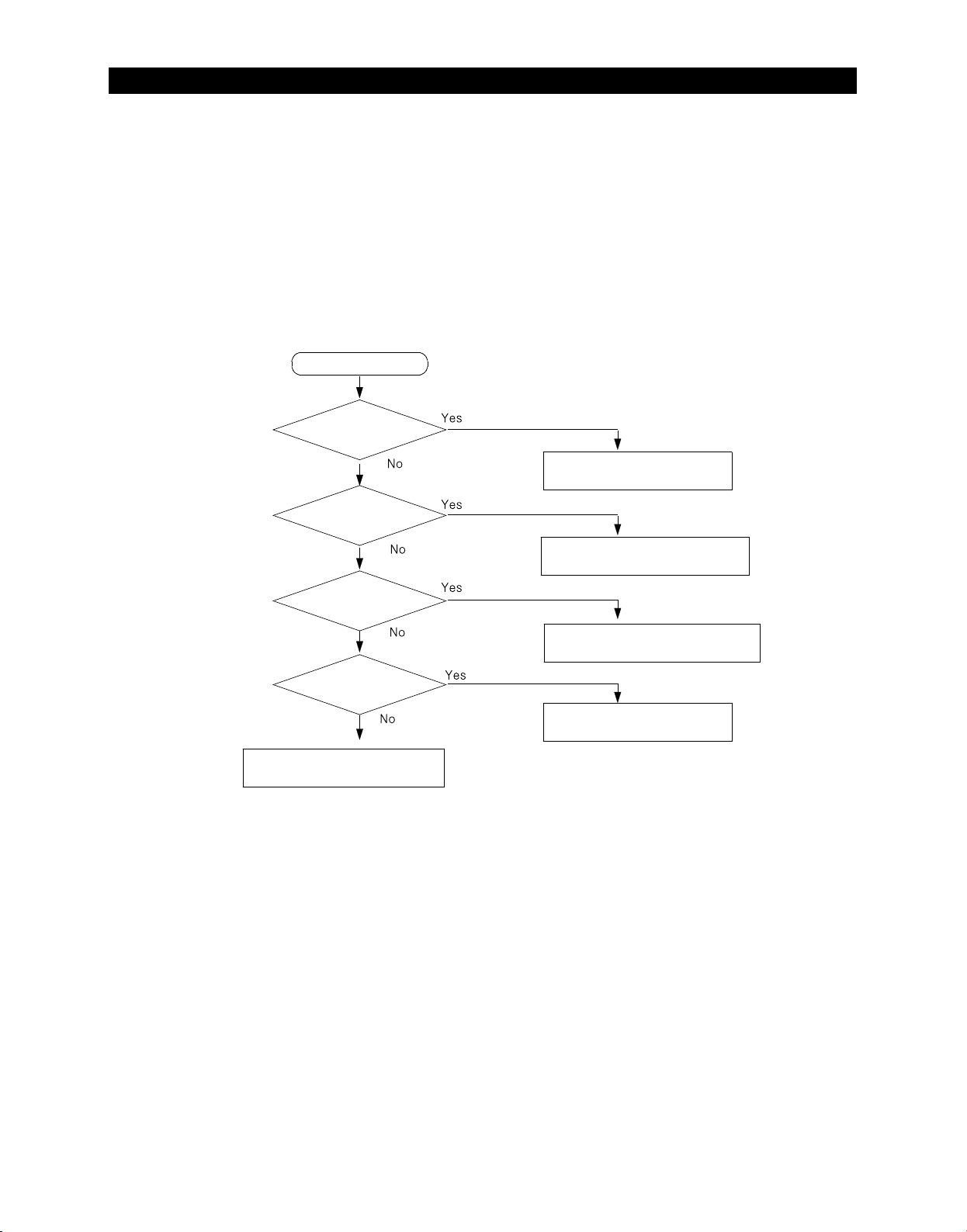
TROUBLESHOOTING
③ If buzzer does not sound
Buzzer is installed on the panel PCB in this model.
If buzzer does not sound when button is pressed, manual operation is started and door is opened,
should separate panel PCB and check the breakage of buzzer and bad soldering.
It is very hard to repair the panel PCB because it consists of SMD assemblies.
It is recommended to replace assembly PCB when the failure associated with panel is occurred
except the minor error such as switch pressing error, surface peeling off and so on.
'dingdong' if press a button
Start
Does it sound
on the front panel?
Does it make a
sound of 'dooropen' alarm when
you are opening the door of freezer or
fridge more than 2 minutes?
MAIN PCB normal,
BUZZER normal
Check the panel PCB with reference
of <how to check Panel Display>
Is the damage
or breakage of the buzzer in
the panel PCB?
Did lead of a component
fall on the vibration plate of
buzzer?
Recheck the button pressing
force and mechanical problem
Replace(repair) buzzer
Replace Panel PCB
Replace buzzer
Replace Panel PCB
75
Page 77
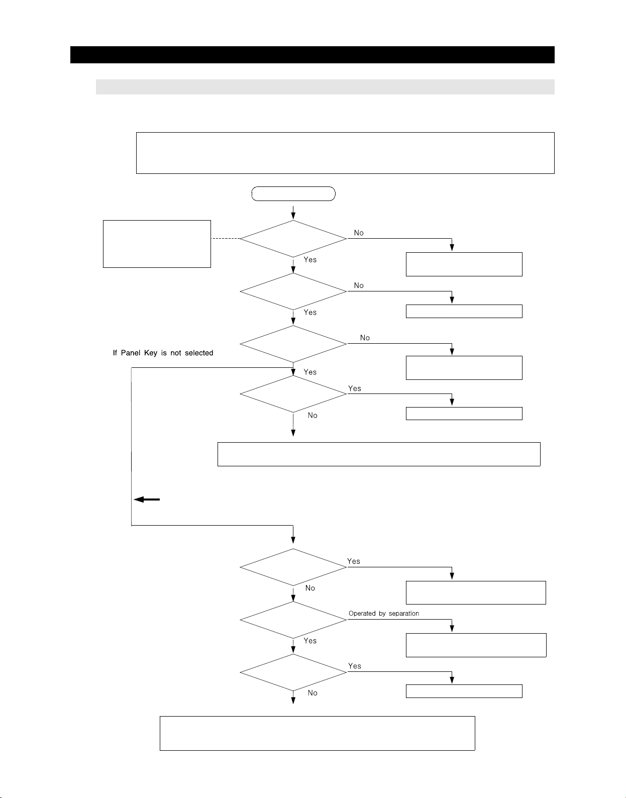
TROUBLESHOOTING
4-2-9. If Panel PCB does not work normally
① When lighting of Panel PCB is disabled or only some LED Lamp are disabled
Be careful to repair because display of this model is installed in the MICOM of internal PCB.
It is recommend to replace PCB MAIN after checking except specified solder touch.
Start
Refer to electronic circuit
diagram in the manual or
circuit diagram on the back
side of the appliance
② If Panel PCB KEY is not selected
※ If it is not repaired with using the basic checking method as above
Is the connector of
upper hinge cover
inserted correctly?
Reinsert connector,
Repair bad contact
Is MAIN PCB
connector (CN50)
inserted correctly?
Reinsert connector of MAIN PCB
Is Upper Hinge
Panel PCB connector
inserted correctly?
Reinsert connector,
Repair bad contact
Is lighting operate
normally when replace
Panel-PCB?
Panel PCB itself has trouble.
①Check the wire of Dispenser part - Upper Hinge Panel - disconnection, short between wires
②Check the wires between fresh food compartment upper cabinet - MAIN PCB - disconnection, short between wires
Are one or more keys
pressed continuously?
Reassemble the PCB ASS'Y /
Enforce the cancelation of pressed keys
Is the PCB system
still operated by separating
of the mechanism?
Reassemble the PCB ASS'Y /
Enforce the cancelation of pressed keys
Is the lighting operated
normally when replace the
Panel-PCB ?
Panel PCB itself has trouble.
①Check the wires of Dispenser part - Upper Hinge Panel - disconnection, short between wires.
②Check the wires of fresh food compartment upper cabinet - disconnection, short between wires.
③Check the short/open of the panel communication and power supply circuit in MAIN PCB.
76
Page 78
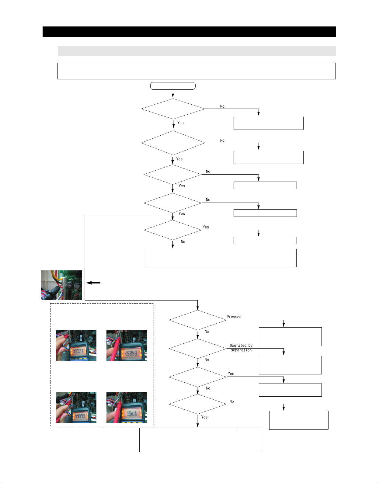
TROUBLESHOOTING
4-2-10. If Pantry Panel PCB is not working normally
You should check the display after door opening because the display of this model operates only when
the fresh food compartment door is opened.
Start
Does fresh food
compartment door switch
operate normally?
Check and repair the switch
* Refer to<how to repair door switch>
Is the connector of
pantry room in fresh food
compartment inserted
If Panel Key is not selected
correctly?
Is MAIN PCB
Connector (CN78) inserted
correctly?
Is signal of MAIN
PCB CN78 normal?
Reinsert Connector,
Repair bad contact
Reinsert connector in MAIN PCB
Check voltage/Replace MAIN PCB
typical PCB Ground
CN1#3(Black)
② If Panel Panel PCB Key is not selected
※ If it is not repaired with using the basic checking method as above
☞ Checking method of voltage Based on
PCB typical Ground CN1#3(Black)
1) Key voltage ; CN78#1"(Purple)
1) select(operating) (0V)
2) LED part voltage ; CN78-"7"(Yellow),
"8"(Pink) → Voltage of CN78 is same as
IC74 #13,#11 voltage.
- Display On (0.7V±0.3V) - Display Off (9.7V±1V)
2) normal(about5.0V ±0.5V)
Is the lighting
operated when replace Pantry
Panel-PCB?
① Check the wires of Pantry Room - disconnection, short between wires
② Recheck the control circuit of MAIN PCB Pantry Panel
③ Check the wire assembling between Panel↔MAIN
Is a key pressed
continuously?
Is the PCB system
still operated by separating
of the mechanism?
Is the lighting operated
when replace Pantry
Panel-PCB?
Is a normal voltage
outputted from MAIN PCB IC74
in the key operating?
① Check the wire of Pantry Room - disconnection, short
between wires
② Check the short/open of the pantry panel lighting
circuit in MAIN PCB.
Panel PCB itself has trouble.
Reassemble PCB ASS'Y /
Enforce the cancelation of
pressed keys
Reassemble PCB ASS'Y /
Enforce the cancelation of
pressed keys
Convertible compartment Panel
PCB itself has trouble.
① Replace MAIN PCB
② Check the short of MAIN
Panel wire
77
Page 79
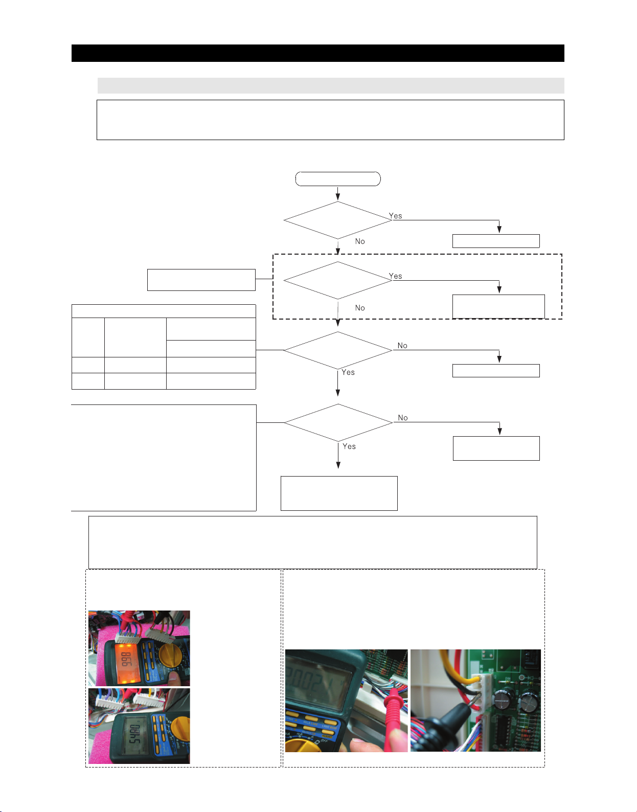
TROUBLESHOOTING
4-2-11. When refrigerator ROOM Lamp does not light up
1. When you replace the lamp of freezer, please power OFF to avoid an electric shock.
2. Please keep in mind you could get burnt by the excessive heating of an incandescent light bulb.
3. Bimetal is installed in the refrigerator LAMP. Check that if LAMP may be OFF by bimetal.
※ The case of fresh food compartment(room) lamp will be explained only.
Because it is possible to repair the other room lamps with the same method.
Start
Is the inside lamp
filament cut?
Repair the inside lamp
Fresh food compartment
Lamp is applied only.
Door & MICOM State
F
Door
MICOM
(#50)
Close
Open
Reference
* The interior lamp relay operates lighting/lightout
according to door open / close.
* If interior lamp does not light, check the noise of relay
operation.
* Noise of relay operation sounds every Door Open /
Close.
* F-LAMP Relay -- RY75
* R-LAMP Relay -- RY76
☞ When measure lamp resistance to the Wire
→ Resistance can be changed by Lamp input voltage.
5V(High)
0V(Low)
Reference
If the door is opened, the contact of door switch will be opened and MICOM will get applied 5V to finally sense Open.
If 5V has been sensed over two minutes afterwards, Door-Open alarm will sound ‘Ding-Dong’for 10 seconds in a oneminute cycle. For
that reason, if the door switch has failure, the refrigerator can make a “Ding-Dong”sound per a oneminute cycle. Please note the step
for its service.
(Actual measurement is below, it can be changed by
performance)
R MICOM(#3)
Right and Left
0V(Low)
5V(High)
☞ Fresh food
compartment lamp
CN70#1(Red) ↔
CN71#1 (Blue) ;
10(33)Ohm±3 Ohm
Lamp ; 60W + 60W
Is Lamp OFF by
bimetal operating?
Wait for returning time
of bimetal
Is the connection
point of R-door switch
normal?
Is the control relay
of the inside lamp in PCB
normal?(RY76)
Check the connection of RDoor
switch and repair the inside lamp
socket
☞ Checking method of Door Switch voltage
- Measuring voltage of Sensor Check Point #5(IC01 MICOM #58) on
PCB or CN30#8(White-black) ↔ CN75#1(Gray)
- Compare time table after measuring
Measuring voltage of CN30#8(white-black)↔CN75#1(Gray) are below
typical PCB Ground CN10#3"(Black)
Repair door switch
Replace PCB and
Replace Relay
☞ Fresh food
compartment lamp
CN70#1(Red) ↔
CN71#3 (Gray) ;
15(66)Ohm±5 Ohm
Lamp ; 60W
78
Page 80
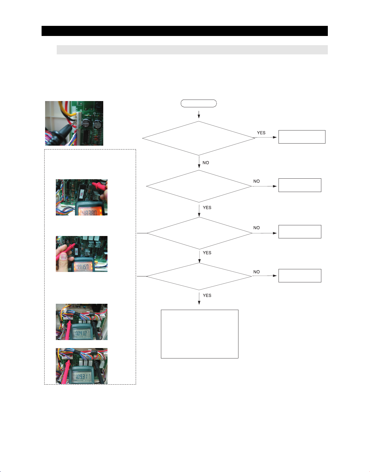
TROUBLESHOOTING
4-2-12. If ICE Water is not supplied
typical PCB Ground CN1#3(Black)
Start
☞ Checking method of voltage Based on
PCB typical Ground CN1#3(Black)
1) Check the voltage of IC73#4(same voltage
as IC02 #12)
- ICE Water valve operating (about 5V±0.5V)
Based on PCB typical Ground CN1#3(Black)
2) IC73 #13 voltage
- ICE Water valve operating (about 0.7V±0.5V)
3) Check the voltage of ICE Water Valve
operating(AC voltage)
=> For checking the Relay RY79 operating.
CN70#1(Red) ↔ CN73#7(Purple)
- ICE Water valve waiting (about AC 0V)
Is the confirming sound of
the valve operation heard when
Ice maker test switch pushed?
Does Main PCB MICOM
#12 have high (5V)output?
Does Main PCB IC73
#13 have about 0.7V
output?
Is the contact point of main
PCB RELAY RY79 normal?
Normal(Check Ice
water valve hose)
Check soldering
short/Replace PCB
Check soldering
short/Replace PCB
Check soldering
short/Replace PCB
- ICE Water valve operating (about AC 110(230)V ± 20%)
MAIN PCB normal
-- Need to check the other parts
① Check the wire between Ice
water valve↔MAIN PCB
② Ice water valve itself has trouble
or bad contact of connector
③ Check the connection hose
79
Page 81
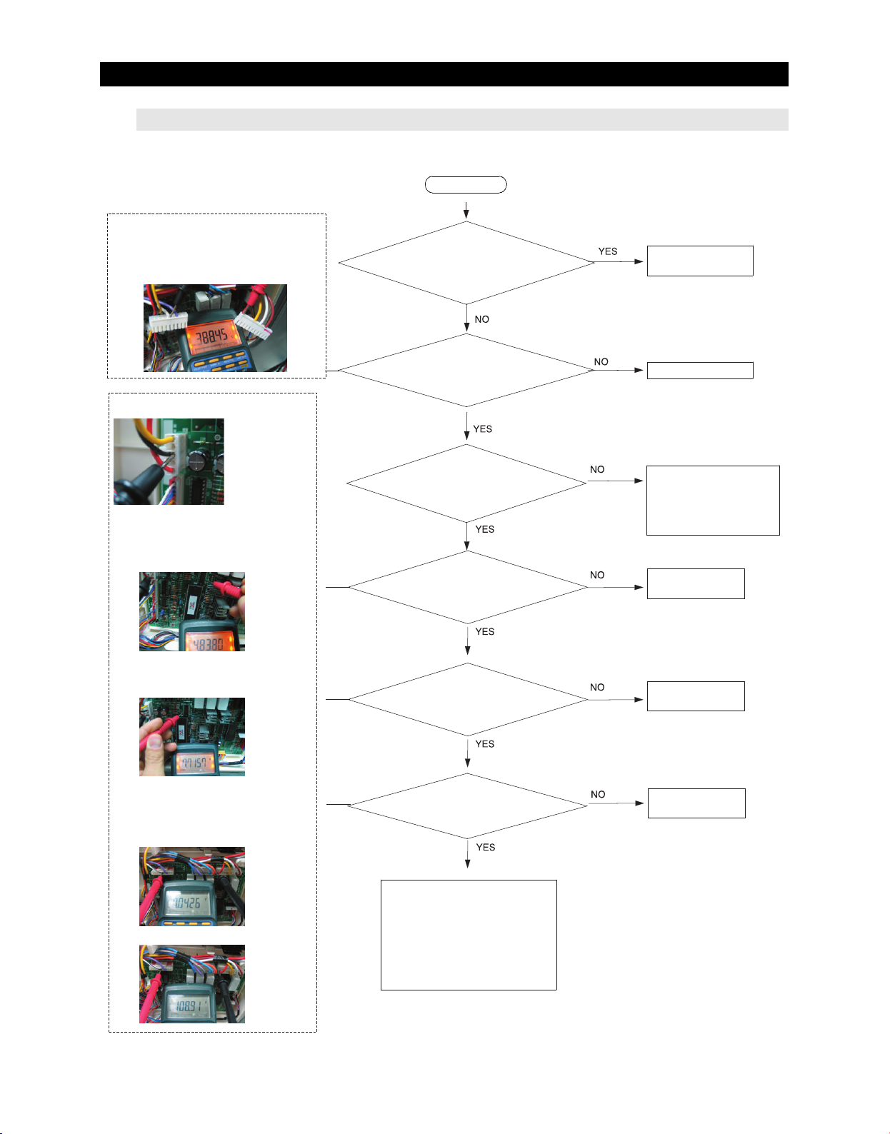
TROUBLESHOOTING
4-2-13. If Water is not supplied
☞ Checking method of Valve resistance (Must
power off for checking)
Resistance can be changed by input voltage.
CN70#1 (Red) ↔ CN73#5 (White-black)
- resistance value ; 388(1.6k)Ohm ± 7%)
** 0Ω: Short trouble / ∞Ω: Open trouble
Start
Is the confirming sound of
the valve operation heard
when dispenser switch
pushed?
Normal(Check Ice
water valve hose)
typical PCB Ground CN1#3(Black)
☞ Checking method of voltage
Based on PCB typical Ground CN1#3(Black)
1) Check voltage of IC73# (same voltage as
IC01#64)
- Water valve operating (about 5V±0.5V)
Based on PCB typical Ground CN1#3(Black)
2) IC73 #14 voltage
- Water valve operating (about 0.7V±0.5V)
Is the valve unit normal?
Is the voltage of PCB IC01
MICOM #15 changed 0V~5V
according to switch On/Off?
Does Main PCB IC73 #3
have about 5V input?
Does Main PCB IC73 #14
have about 0.7V output?
Replace Valve
1) Check the dispensing
lever
2) Check switch unit/ wiring
connection
3) Replace PCB
Check soldering
short/Replace PCB
Check soldering
short/Replace PCB
3) Check the voltage of Water Valve operating
(AC voltage)
=> For checking the Relay RY7A operating.
CN70#1(Red) ↔ CN73#5(White-black)
- ICE Water valve waiting (about AC 0V)
- ICE Water valve operating (about AC 110(230)V ± 20%)
Is the contact point of main
PCB RELAY RY7A normal?
MAIN PCB normal
-- Need to check the other parts
① Check the wire between water valve ↔
MAIN PCB
② Ice water valve itself has trouble or bad
contact of connector
③ Check the connection hose
④ Check the operation between Panel PCB
and MAIN PCB for Communication.
80
Check soldering
short/Replace PCB
Page 82
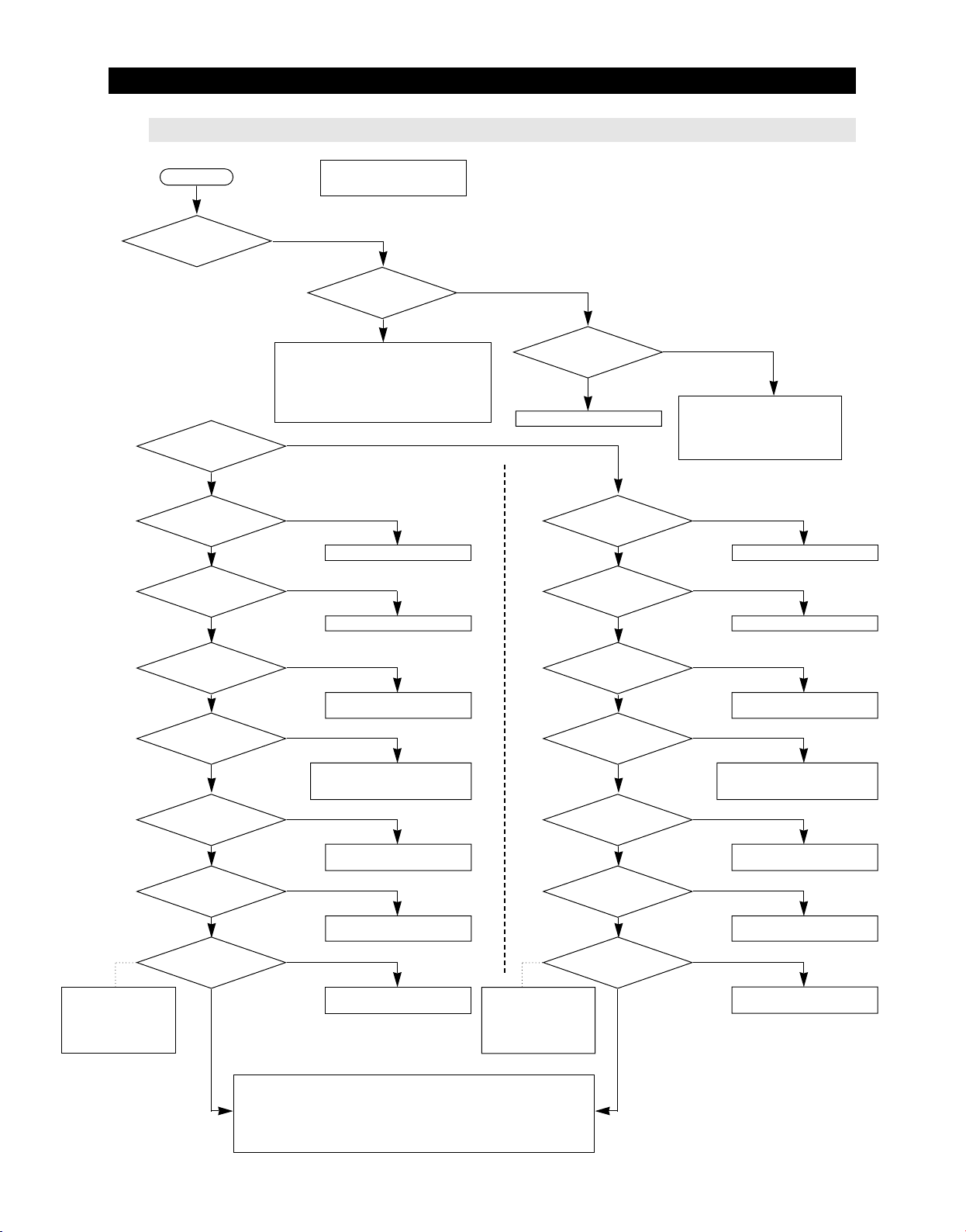
TROUBLESHOOTING
4-2-14. If Cubed or Crushed Ice is not supplied
Start
Are Ices ejected?
Which mode is
selected?
Cubed Ice
Is Cubed Ice ejected?
No
Is Cubed Ice mode
selected on the
panel PCB?
Yes
Freezer door shall be
closed during operaion.
No
Are Ices in the Ice bucket?
① Check the Ice making switch
② Check the DOOR Switch
③ Check the Ice movin motor
④ Check the wiring connections of Ice moving motor
⑤ Check if the COVER ICE ROUTE opens
⑥ Check the Q706 movement related with
AUGER_MOTOR safety
No
Crushed Ice
Cubed Ice ejected
Normal Operation status
No
Cubed Ice selected
Is “Ice Off” mode
selected on the display
panel?
Yes
Cancel the “Ice Off”
Is Crushed Ice ejected?
No
Is Crushed Ice mode
selected on the
panel PCB?
Yes
No
① Check the water pipe
: bending / Shut off
② heck route of ice check solenoid
③ Check he Ice Maker wiring
Yes
Normal Operation status
No
Crushed Ice selected
Is the CUBE MOTOR
change into 0V when
Is IC73 #1,2 changed
into 5V when pressing
point of RY7B & RY7C RELAY
After disconnecting the
CN70, CN71, CN72 and
CN73, measure the both
ends of contact points of
RY7B, RY7C
positioned at cubed
ice mode?
Yes
Is MICOM IC01 #15
press Ice switch?
Yes
Is the Dispenser
Cover opened?
Yes
Ice Switch?
Yes
Is the contact
changed into 0Ω
Yes
If MAIN PCB is normal
- Need to check the other parts
① AUGER MOTOR ↔ MAIN PCB
Check the door wiring connections.
② CUBE MOTOR ↔ MAIN PCB
Check the door wiring connections/trouble their own or bad wiring connections.
No
Check the wire connections/
Cube Solenoid
No
- Check the Ice switch has trouble itself
- Check the wire connections
- Replace the MAIN PCB
No
check the WIRE & Motor/
Replace the MAIN PCB
No
Replace the MAIN PCB
(Errors on IC73)
No
- RY7B, RY7C RELAY Error
- Replace the MAIN PCB
Is the CUBE MOTOR
positioned at cubed
Is MICOM IC01 #15
change into 0V when
press Ice switch?
Is the Dispenser
Cover opened?
Is IC73 #2 changed
into 5V when pressing
point of RY7B RELAY
changed into 0Ω
After disconnecting the
CN70, CN71, CN72 and
CN73, measure the both
ends of contact points of
RY7B.
ice mode?
Yes
Yes
Yes
Ice Switch?
Yes
Is the contact
Yes
No
Check the wire connections/
Motor Cube
No
- Check the Ice switch has trouble itself
- Check the wire connections
- Replace the MAIN PCB
No
check the WIRE & Motor/
Replace the MAIN PCB
No
Replace the MAIN PCB
(Errors on IC73)
No
- RY7B RELAY Error
- Replace the MAIN PCB
81
Page 83
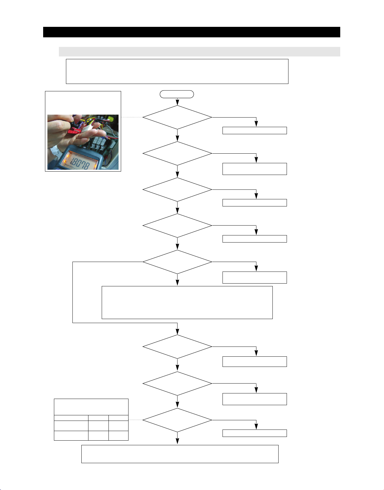
TROUBLESHOOTING
4-2-15. If Cover Ice Route Moor(Geard Motor) is not working normally
Caution
1. When replacing the Cover Ice Motor, pull out the plug to avoid an electric shock.
2. Be careful! When disassemble the Cover Ice Motor, spring can jumped out and may cause personal injury.
3. Motor will rotate continuously when the Motor Switch is not sensed.
☞ Checking Mehod of Cover Ice
Route Motor Resistance
(Make sure to work after Power Off)
The Resistance is variable
according to the input voltage.
When the MOTOR
rotates.
Start
Does GEARED MOTOR
work properly?
Yes
Is Cubed or Crushed
Ice mode selected on the
LED PANEL?
Yes
Is the DISPENSER
switch selected?
Yes
Does the wiring at the
both side of motor connected
properly?
Yes
Is the AC input voltage
applied to the both ends
of the motor?
No
No
Replace the MOTOR
No
Cubed or Crushed Ice is selected
on the LED PANEL PCB
No
Select the DISPENSER switch
No
Check the WIRE
Yes
Check the MOTOR/Check any
interference on MOTOR rotation
① Check CN70①, CN73⑨, voltage is applied to the PCB CASE.
② Check the SSR73 SHORT/OPEN of Cover Ice Motor control circuit in the MAIN PCB.
③ Check any SHORT/OPEN of wiring connections between PCB CASE and MAIN PCB.
(CN70 ①, CN73 ⑨)
NOTE. <Make sure that the plug is tuned off before you work, Check the Resistance value>
Operating Condition of Dispenser
Open/Close
CN50 - Switch 1,2 Operating
Ice Route Switch 1
CN50 - “9” (Purple)
Ice Route Switch 2
CN50 - “10” (White)
① Main PCB - Check the wire OPEN/SHORT between the Cover Ice Motor Rotation sensin switches.
② Check the Short of Cover Ice Motor Control Circuit SSR73 in the MAIN PCB.
③ Replace the MAIN PCB or the Dispenser Cover Motor.
OpenClose
0V
0V
Is the sensing
SWITCH connection
normal?
Yes
Is the switch
pressed area normal when
motor rotates?
Yes
Are the voltage of
CN10-”3” and CN50-”9”,
0V
0V
“10” normal?
No
No
Check/Repair the Housing
connector
No
Check/Repair the Motor Rotation
pressing area
Yes
Normal
82
Page 84

5 . EXPLODED VIEW& PARTS LIST
5-1) FREEZER ························································84
5-2) REFRIGERATOR ····················································87
5-3) CABINET ·························································91
5-4) DISASSEMBLY OF FREEZE DOOR ········································95
5-5) DISASSEMBLY OF REFRIGERATOR DOOR LEFT ·····························98
5-6) DISASSEMBLY OF REFRIGERATOR DOOR RIGHT ····························101
83
Page 85
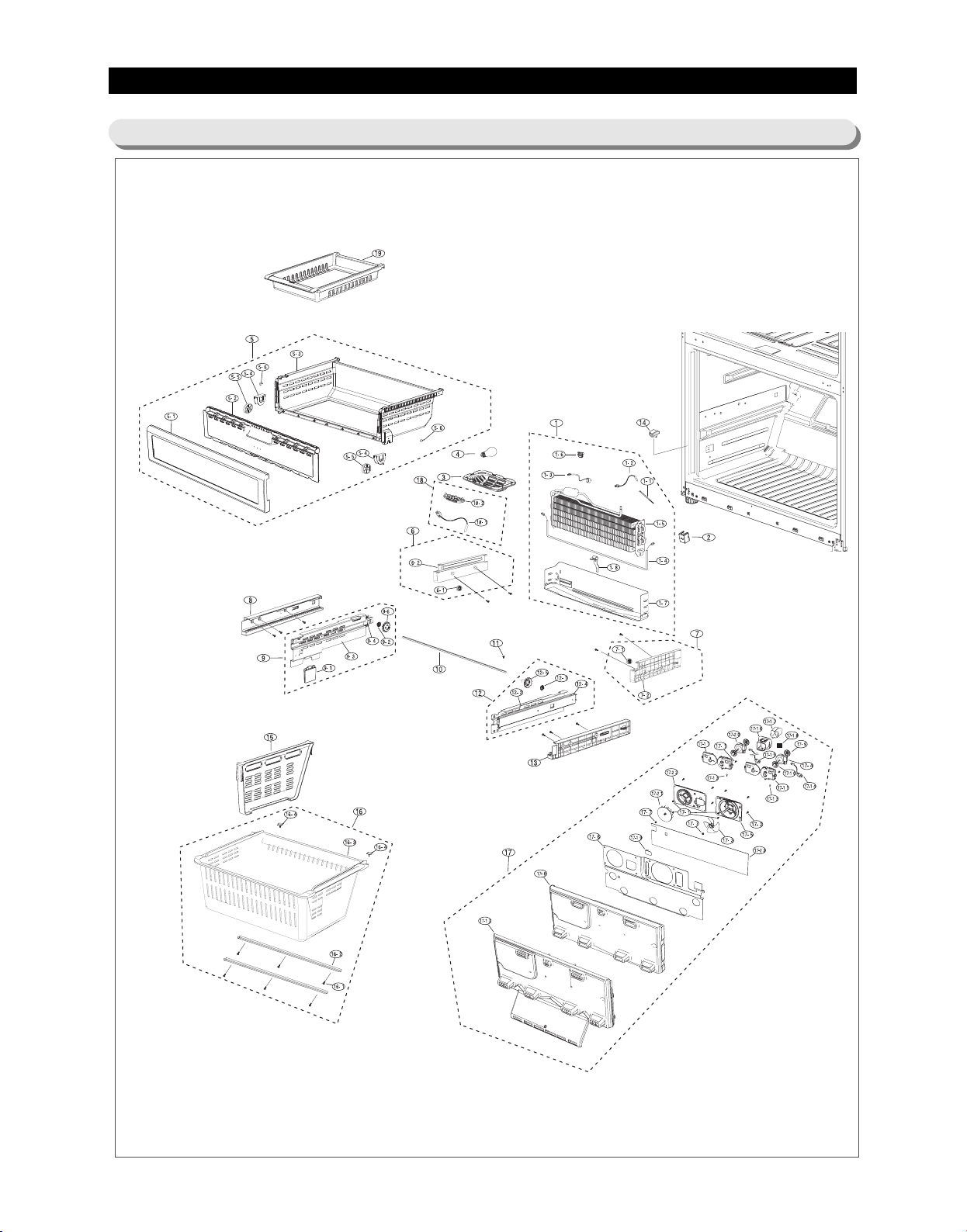
EXPLODED VIEW& PARTS LIST
5-1) Freezer
84
Page 86
EXPLODED VIEW& PARTS LIST
■■
Parts List of Freezer
NNOO
CCOODDEE--NNOO
1
DA96-00459A
1-1
6501-000123
1-2
DA32-00027B
1-3
DA47-00243R
1-4
DA47-00244C
1-5
DA59-00361A
1-6
DA61-02901A
1-7
DA61-04149A
1-8
DA61-03644A
2
DA63-02902B
3
DA63-03420A
4
4713-001223
5
DA97-06260A
5-1
DA63-04115A
5-2
DA63-03436A
5-3
DA63-04114A
5-4
DA61-04154A
5-5
DA66-00554A
5-6
DA63-40167A
5-7
DA66-10104A
5-8
DA71-20145A
6
DA97-06083A
6-1
DA66-10104A
6-2
DA61-04108A
7
DA97-06084A
7-1
DA66-10104A
7-2
DA61-04109A
8
DA63-03414A
9
DA97-04836A
9-1
DA34-00047A
9-2
DA61-03154A
9-3
DA61-03156A
9-4
DA61-03158A
9-5
DA61-03285A
9-6
DA66-00436A
10
DA66-00437A
11
DA67-00859C
12
DA97-04835A
12-1
DA61-03154A
12-2
DA61-03157A
12-3
DA61-03285A
12-4
DA61-03333A
12-5
DA66-00435A
13
DA63-03415A
14
DA34-10120E
15
DA61-03416A
16
DA97-06258A
16-1
6002-000213
16-2
DA61-03160A
16-3
DA63-04116A
16-4
DA63-04313A
17
DA97-05343B
ASSY EVAP-FRE ICE
CABLE TIE
SENSOR TEMP
THERMO BIMETAL-PROTECTOR
HEATER-METAL SHEATH
EVAP-FRE ICE
FIXER-SENSOR EVAP
PLATE-DRAIN FRE
PLATE-EVAP HEATER
COVER-FIXER HOUSING V
COVER-LAMP FRE
LAMP-INCANDESCENT
ASSY TRAY-FRE UPP
COVER-TRAY FRE UPP A
COVER-TRAY FRE UPP B
TRAY FRE-UPP
FIXER-ROLLER TRAY FRE UPP
ROLL-TRAY FRE UPP
GROMMET-COVER CHIL
ROLLER-FRE
FIXER-ROLLER
ASSY RAIL-SLIDE UPP L
ROLLER-FRE
RAIL-SLIDE UPP L
ASSY RAIL-SLIDE UPP R
ROLLER-FRE
RAIL-SLIDE UPP R
COVER-RAIL LOW L
ASSY RAIL-SLIDE LOW L
SWITCH PRESSURE
FIXER-GEAR
HANGER-RAIL LOW L
RAIL-SLIDE LOW L
HANGER-RIVET
GEAR-L
SHAFT-GEAR
CAP-DOOR HANDLE
ASSY RAIL-SLIDE LOW R
FIXER-GEAR
HANGER-RAIL LOW R
HANGER-RIVET
RAIL-SLIDE LOW R
GEAR-R
COVER-RAIL LOW R
SWITCH DOOR-F
GUIDE-DRAWER BOX
ASSY TRAY-DRAWER BOX
SCREW-TAPPING
REINF-DRAWER BOX
TRAY-DRAWER BOX
GROMMET-TRAY DRAWER BOX
ASSY COVER-EVAP FRE ICE
SSPPEECC
08AW-PJT,115V,2
DACT140,W3.6,L146,NTR,NYLON66
502AT,AW-PJT,-40~110?,5V,R-DEF-SENSOR,YEL,400MM
AW-PJT(F),BT-121-M, PW-5M1N,125 / 250V,10 / 5A,60?,40?,100MΩ
AW-PJT,240W,115V,55.1,F-ROOM
PIN,115V,AW-PJT
CORE-PJT,PP,NTR
AW-PJT(RF-267),GALVALUM,T0.3
AL,T0.7
NEXT,GALVALUM,T0.3
AW,GPPS,NTR
120V,500mA,60W,47x84mm
AW-PJT,BEST
AW-PJT,HIPS
AW-PJT,GPPS
AW-PJT(BEST),HIPS(HF-1760SF)
AW-PJT,POM,1.8,NATURAL
AW-PJT,POM,42.2,-,NATURAL,-,PVC COATING
T3.0,SILICON
POM,D22
PA
AW-PJT
POM,D22
ABS WHITE
AW-PJT
POM,D22
ABS, WHITE
AW-PJT,ABS,COOL WHITE
AW-PJT
AW-PJT,HIPS,COOL WHITE
AW-PJT,POM,NTR
AW-PJT,SECC1,T2.0
AW-PJT,STS430
AW-PJT,BSW2
AW-PJT,POM,NTR
AW-PJT,SM25C
CORE,POM,INOX,SC-06034R
AW-PJT
AW-PJT,POM,NTR
AW-PJT,SECC1,T2.0,COOL
AW-PJT,BSW2
AW-PJT,STS430
AW-PJT,POM,NTR
AW-PJT,ABS,COOL WHITE
slide,250V,0.5A,cool white
AW-PJT,PP,COOL WHITE
AW-PJT
TH,+,-,1,M4,L12,ZPC(WHT)
AW-PJT,SHP1,T2.6,BL
AW-PJT,PP,COOL WHITE
SILICON
AW-PJT(RF267,GE)
85
QQUUAANN
TTIITTYY
1
3
1
1
1
1
1
1
1
1
1
1
1
1
1
1
2
2
2
2
2
1
1
1
1
1
1
1
1
1
1
1
1
3
1
1
1
1
1
1
3
1
1
1
1
2
1
6
2
1
2
1
RREEMMAARRKKPPAARRTT NNAAMMEE
Page 87
EXPLODED VIEW& PARTS LIST
■■
Parts List of Freezer
NNOO CCOODDEE--NNOO RREEMMAARRKKPPAARRTT NNAAMMEE SSPPEECC
17-1
6002-000213
17-2
6002-000215
17-3
DA31-00124A
17-4
DA31-00146C
17-5
DA61-03183A
17-6
DA61-03618A
17-7
DA61-20128A
17-8
DA62-01527A
17-9
DA63-01146A
17-10
DA63-01808A
17-11
DA63-01809A
17-12
DA63-03740A
17-13
DA63-40167A
17-14
DA96-00042K
17-15
DA96-00042H
17-16
DA67-01774A
17-17
DA61-03724A
17-18
DA47-00261A
17-19
DA61-03627A
17-20
DA31-00146E
17-21
DA31-00123A
17-22
DA61-03617A
17-23
DA62-01526A
18
DA97-02019B
18-1
DA63-10467B
18-2
DA32-00011U
19
DA63-03696A
SCREW-TAPPING
SCREW-TAPPING
FAN-AX100W4CC-T1
MOTOR BLDC
CASE-MOTOR FRE
PLATE-INS EVAP FRE ICE
SPRING ETC-FAN
INSULATION-EVAP FRE ICE
GROMMET-MOTOR,REAR
GROMMET-MOTOR,FRONT
COVER MOTOR-BLDC
COVER EVAP-FRE ICE
GROMMET-COVER CHIL
ASSY-HARNESS MOTOR
ASSY-HARNESS MOTOR
DUCT-ICE SUB
PLATE-DRAIN ICE
HEATER CORD-DUCT(FRE)
PLATE-DRAIN FAN
MOTOR FAN-BLDC
FAN-BACKWARD
CASE-MOTOR FRE ICE
SEAL-COVER EVAP FRE
ASSY COVER-SENSOR
COVER-SENSOR
SENSOR TEMP
TRAY-FRE UPP SUB
TH,+,1,M4,L12,ZPC(WHT),SWRCH18A
TH,+,1,M4.0,L16,ZPC(WHT),SWRCH18A
FAN-AX100W4CC-T1
DC12V,150mA,2.1W
AW-PJT,BUBBLE PP
GALVALUME,T0.3
STS304,PI7.8,OD1.0
FOAM-PS
NBR,ID6.5,OD42
NBR,BLACK
PP,NTR
PP(BJ-730)
SILICON
R-Fan/ F-Fan
Ice-room Fan
PP(BJ-730)
GALVALUME,T0.3
4W,115V,3306Ω
AL,T0.8
DREP5020LB
ABS(HP-0760)
PP(BJ-730),WHITE
FOAM-PE+AL,T2,W147,L640
HIPS,SC-02740R,COOL WHITE
PX-41C,AW-PJT,-40~110?,5V
AW-PJT,SAN(HF-5661)
QQUUAANN
TTIITTYY
6
8
1
1
1
1
2
1
2
2
2
1
2
1
1
1
1
1
1
1
1
1
1
1
1
1
86
Page 88
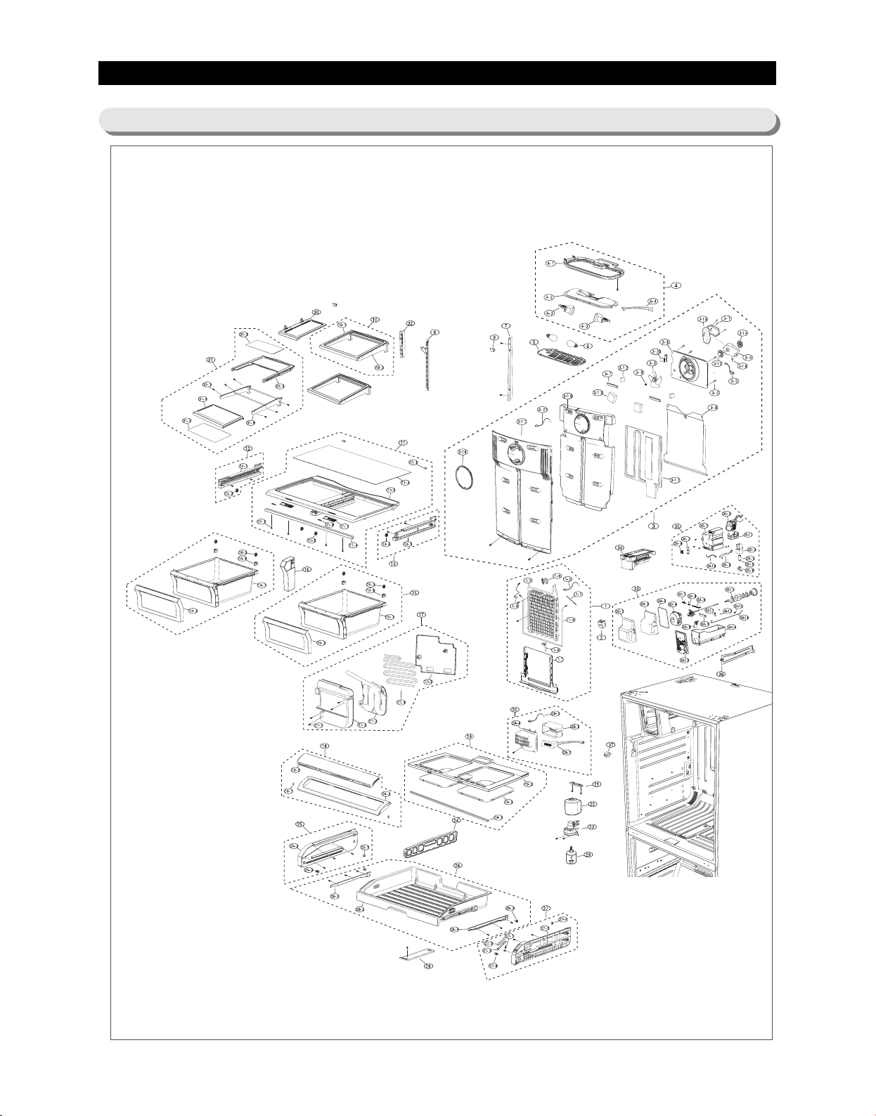
EXPLODED VIEW& PARTS LIST
5-2) Refrigerator
87
Page 89
EXPLODED VIEW& PARTS LIST
■■
Parts List of Refrigerator
NNOO
CCOODDEE--NNOO
1
DA96-00461A
1-1
6501-000123
1-2
DA32-00027B
1-3
DA47-00243S
1-4
DA47-00244D
1-5
DA59-00357B
1-6
DA61-03683A
1-7
DA61-04148A
1-8
DA61-03644A
2
DA63-02902B
3
DA97-06197A
3-1
6002-000213
3-2
6002-000215
3-3
DA31-00124A
3-4
DA31-00146C
3-5
DA96-00042J
3-6
DA61-03181A
3-7
DA61-03182A
3-8
DA61-03186A
3-9
DA61-20128A
3-10
DA62-01760A
3-11
DA62-01382A
3-12
DA62-01383A
3-13
DA62-01423A
3-14
DA63-01146A
3-15
DA63-01808A
3-16
DA63-01809A
3-17
DA63-04139A
3-18
DA63-40167A
3-19
DA64-02065A
3-20
DA61-03599A
3-21
DA32-10150X
4
DA97-04842E
4-1
DA61-03163A
4-2
DA61-03169A
4-3
DA47-40001D
4-4
DA47-00243D
5
DA63-03773A
6
4713-001223
7
DA61-03180A
8
DA97-05545A
9
DA67-01688A
10
DA97-04896A
10-1
DA67-01607A
10-2
DA97-04870A
11
DA97-05382A
11-1
6002-000213
11-2
DA01-00400B
11-3
DA61-03166A
11-4
DA61-03173A
11-5
DA63-03761A
11-6
DA64-00817A
ASSY EVAP-REF
CABLE TIE
SENSOR ASSY
THERMO BIMETAL-PROTECTOR
HEATER-METAL SHEATH
EVAP REF
FIXER-SENSOR
PLATE-DRAIN REF
PLATE-EVAP HEATER
COVER-FIXER HOUSING,V
ASSY COVER-EVAP REF
SCREW-TAPPING
SCREW-TAPPING
FAN-AX100W4CC-T1
MOTOR BLDC
WIRE HARNESS-MOTOR
CASE-MOTOR REF
GUIDE-INS EVAP REF
PLATE-INS EVAP REF
SPRING ETC-FAN
INSULATION-EVAP REF
INSULATION-EVAP REAR
INSULATION-EVAP SUB
INSULATION-EVAP DUCT
GROMMET-MOTOR,REAR
GROMMET-MOTOR,FRONT
COVER MOTOR-BLDC
COVER-EVAP REF
GROMMET-COVER CHIL
TRIM-COVER EVAP REF
PLATE-HOUSING REF
SENSOR-ASSY
ASSY CASE LAMP-REF
CASE-LAMP REF
PLATE LAMP REF
LAMP HOLDER ASSY
THERMO BIMETAL PROTECTOR
COVER-LAMP REF
LAMP INCANDESCENT
ANGLE-SHELF REF SIDE
ASSY ANGLE SHELF REF
CAP-ANGLE
ASSY SHELF GLASS REF SLIDE
SHELF GLASS REF SLIDE
ASSY SHELF HANGER SLIDE
ASSY COVER-VEG
SCREW-TAPPING
GLASS-COVER VEG
FIXER-COVER VEG
REINF-COVER VEG
COVER-VEG REF
KNOB-HUMIDITY
QQUUAANN
SSPPEECC
AW-PJT(BEST,GE),115V/120W
DACT140,W3.6,L146,NTR,NYLON66
PX41C,502AT,AW-PJT,40~110,5V,RDEF SENSOR,YEL,400MM
AW-PJT(R),BT-121-M, PW-5M1N,125 / 250V,10 / 5A,60?,40?,100MΩ
AW-PJT,120W,115V,110.2?,RROOM
AW-PJT
ATOP,EVAP,PP,NTR,ALL
AW-PJT('08),GALVANUME,T0.3
AL,T0.7
NEXT,GALVALUM,T0.3
AW-PJT(BEST)
TH,+,1,M4,L12,ZPC(WHT),SWRCH18A
TH,+,1,M4.0,L16,ZPC(WHT),SWRCH18A
TD-PJT,ABS
2950,DC12V,150mA,2.1W,MOTORBLDC
AW-PJT,R-Fan/ F-Fan
AW-PJT,BUBBLE PP,NTR
AW-PJT,ABS,NTR
AW-PJT,GALVANUME,T0.4
STS304,PI7.8,OD1.0,FD
SAMSUNG 08,FOAM-PS,33 MAGNIFICATION
AW-PJT,FOAMPS
AW-PJT,FOAMPS
AW-PJT,FOAMPS,T20,W44.5,L45
ATOP,NBR,ID6.5,OD42,BLK,BLDC
BLDC,NBR,BLACK,H20
BLDCNEW,PP,NTR,BJ730
AW-PJT(SAMSUNG 08),PP,COOL-WHITE(SC-02740R)
T3.0,SILICON,NTR
AW-PJT,ABS,COOL-WHITE
GALVALUME,T0.3
YEL,500MM
AW(GE 08)-PJT
AW,HIPS,COOL WHITE
AW,SBHG1,T0.4
E26,250V,660W,TE5006F
AW-PJT(R-Lamp),BT-121-M, PW-5M1N,125 / 250V,10 / 5A,60?,40?,100MΩ
AW,PC,CRYSTAL
120V,500mA,60W,47x84mm
AW,SECC1,T2.0,COOL-WHITE
AW,SECC1,T2.0,COOL-WHITE
AW-PJT,HIPS,COOL-WHITE
PP+GLASS,COOL WHITE
AW-PJT
TH,+,1,M4,L12,ZPC(WHT),SWRCH18A
756*343,T3.2,1°∆ PRINT
AW,HIPS,COOL-WHITE
AW-PJT,SHP1,T2.9,BLACK
AW,HIPS,COOL-WHITE
QUEEN,ABS
88
TTIITTYY
1
4
1
1
1
1
1
1
1
1
1
3
4
1
1
1
1
2
1
1
1
1
2
2
1
1
1
1
1
1
1
1
1
1
1
2
1
1
2
1
1
1
2
1
1
1
4
1
2
1
1
2
RREEMMAARRKKPPAARRTT NNAAMMEE
Page 90
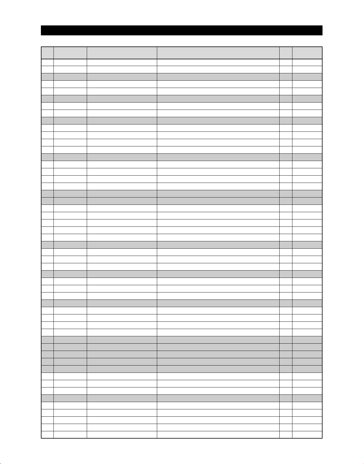
EXPLODED VIEW& PARTS LIST
■■
Parts List of Refrigerator
NNOO CCOODDEE--NNOO RREEMMAARRKKPPAARRTT NNAAMMEE SSPPEECC
11-7
DA66-00438A
11-8
DA66-10104A
12
DA97-04839A
12-1
DA61-03172A
12-2
DA66-10104A
13
DA97-04840A
13-1
DA61-03177A
13-2
DA66-10104A
14
DA97-04846A
14-1
DA61-03165A
14-2
DA63-03426A
14-3
DA66-10104A
14-4
DA71-20145A
15
DA97-05381A
15-1
DA61-03652A
15-2
DA63-03760A
15-3
DA66-10104A
15-4
DA71-20145A
16
DA97-05465A
17
DA97-05033D
17-1
6002-000213
17-2
DA63-03449A
17-3
DA97-02650G
17-4
DA63-03843A
17-5
DA47-00264A
18
DA97-05383C
18-1
DA63-40167A
18-2
DA63-03764A
18-3
DA63-03765A
19
DA97-05370A
19-1
DA61-03174A
19-2
DA67-01781A
19-3
DA64-02235A
20
DA97-06324A
20-1
DA31-00071C
20-2
DA32-00006R
20-3
DA62-01380A
20-4
DA63-04274A
21
DA61-03202A
22
DA63-03685B
23
DA97-01666Y
24
DA61-03167A
25
DA97-05371B
25-1
DA61-03176A
25-2
DA63-03762A
25-3
DA97-05297B
26
DA97-04847D
26-1
6002-000213
26-2
DA61-03164A
26-3
DA97-05296B
26-4
DA97-04837A
26-5
DA97-04838A
LEVER-HUMIDITY
ROLLER-FRE
ASSY RAIL-VEG L
RAIL-VEG L
ROLLER-FRE
ASSY RAIL-VEG R
RAIL-VEG R
ROLLER-FRE
ASSY CASE-VEG REF
CASE-VEG REF
COVER-VEG FRONT
ROLLER-FRE
FIXER-ROLLER
ASSY CASE-VEG REF R
CASE VEG REF R
COVER VEG FRONT R
ROLLER FRE
FIXER ROLLER
ASSY-PARTITION VEG
ASSY-COVER WATER TANK
SCREW-TAPPING
COVER-TANK WATER
ASSY TANK WATER
COVER HEATER WATER TANK
HEATER WATER TANK
ASSY COVER-SLIDE PANTRY
GROMMET-COVER SLIDE
COVER-SLIDE PANTRY A
COVER-SLIDE PANTRY B
ASSY SHELF-PANTRY
REINF-SHELF PANTRY
SHELF-PANTRY
WINDOW SHELF PANTRY
ASSY COVER-MOTOR DAMPER
DAMPER MOTOR
SENSOR TEMP-PANTRY
INSULATION-MOTOR DC DAMPER
COVER-MOTOR DC DAMPER
GUIDE-FRENCH
COVER-WATER FILTER
ASSY CASE-FILTER
GUIDE-PANTRY
ASSY COVER-RAIL PANTRY L
SUPPORT-ROLLER PANTRY
COVER-RAIL PANTRY L
ASSY ROLLER B
ASSY CASE-PANTRY
SCREW-TAPPING
CASE-PANTRY
ASSY ROLLER A
ASSY RAIL-PANTRY L
ASSY RAIL-PANTRY R
AW,HIPS,COOL-WHITE
POM,D22
AW-PJT
AW,HIPS,COOL-WHITE
POM,D22
AW-PJT
AW,HIPS,COOL-WHITE
POM,D22
AW-PJT
AW,SAN,NTR
AW,HIPS,COOL-WHITE
POM,D22
PA
SAN,NTR
HIPS,COOL WHITE
POM
PA
AW-PJT
TH,+,1,M4,L12,ZPC(WHT),SWRCH18A
AW-PJT,PP,COOL-WHITE
PP(BJ-730)
3W,DC 12V,48.0
AW-PJT BEST
T3.0,SILICON,NTR
AW,GPPS,NTR
AW,HIPS,COOL WHITE
AW-PJT
AW-PJT,SECC1,T1.2,COOL WHITE
HIPS,COOL WHITE
GPPS,NTR
AW-PJT
DC12V,600mA,BBC-PJT
PX-41C,502AT,AW-PJT
AW-PJT,FOAMPS,NTR
AW2-PJT,PP,COOL WHITE
AW-PJT,POM,COOL-WHITE(SC02740R)
AW-PJT,HIPS,COOL-WHITE
AW-PJT
AW,PP,COOL-WHITE
AW-PJT(BEST,GE)
AW-PJT,NBR,NTR
AW,HIPS,COOL-WHITE
AW-PJT,Ni-Zn
AW-PJT,COOL WHITE,ROLLER(Ni-Zn)
TH,+,1,M4,L12,ZPC(WHT),SWRCH18A
AW,HIPS,COOL-WHITE
AW-PJT,Ni-Zn
AW-PJT
AW-PJT
Ω
89
QQUUAANN
TTIITTYY
2
2
1
1
1
1
1
1
1
1
1
2
2
1
1
1
2
2
1
1
2
1
1
1
1
1
2
1
1
1
1
1
2
1
1
1
1
1
1
1
1
1
1
1
1
1
1
6
1
2
1
1
Page 91
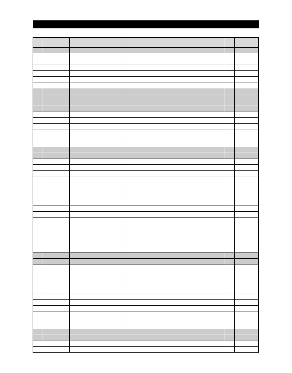
EXPLODED VIEW& PARTS LIST
■■
Parts List of Refrigerator
NNOO CCOODDEE--NNOO RREEMMAARRKKPPAARRTT NNAAMMEE SSPPEECC
27
DA97-05384C
27-1
6002-000630
27-2
DA41-00423C
27-3
DA64-02246C
27-4
DA61-03176A
27-5
DA63-03763A
27-6
DA97-05297B
28
DA61-03175A
29
DA29-00003B
30
DA97-05240A
31
DA97-05359A
31-1
6002-001397
31-2
DA01-00422A
31-3
DA01-00428A
31-4
DA67-01778A
31-5
DA67-01779A
31-6
DA91-02545A
32
DA61-03591A
33
DA97-05239A
33-1
DA63-03687A
33-2
DA62-01475A
33-3
DA63-03737A
33-4
DA63-03686A
33-5
DA62-01569A
33-6
DA61-03505A
33-7
DA66-00476A
33-8
DA61-03506A
33-9
DA66-00477A
33-10
DA63-03688A
33-11
DA66-00475A
33-12
DA67-01719A
33-13
DA65-00046A
33-14
DA63-03689A
33-15
DA61-20124D
33-16
DA66-00478A
34
DA97-05422A
35
DA97-05246A
35-1
DA61-03517A
35-2
DA31-00105E
35-3
DA74-40151G
35-4
DA63-90008A
35-5
DA66-90003A
35-6
DA61-60001A
35-7
DA61-01659B
35-8
DA71-00163A
35-9
DA96-00036N
35-10
DA32-00011U
35-11
DA63-02012B
36
DA63-03691A
37
DA34-00033B
ASSY COVER-RAIL PANTRY R
SCREW-TAPPING
PBA PANEL-PANTRY
INLAY-CONTROL PANEL
SUPPORT-ROLLER PANTRY
COVER-RAIL PANTRY R
ASSY ROLLER B
SUPPORT-PANTRY
FILTER WATER-ASSY
ASSY SHELF REF FOLD
ASSY SHELF QUICK SPACE
SCREW TAPPING
GLASS SHELF QUICK SPACE A
GLASS SHELF QUICK SPACE B
SHELF QUICK SPACE A
SHELF QUICK SPACE B
ASSY HANGER QUICK SPACE
ANGLE-SHELF REF SIDE L
ASSY-TRAY ICE BUCKET
COVER-ICE BUCKET A
INSULATION-COVER ICE BUCKET
GASKET-COVER ICE BUCKET
COVER-CRUSHER
INSULATION-COVER ICE BUCKET-SUB
GUIDE-CRUSHER
LEVER-ICE BUCKET B
SPRING ETC-COVER BUCKET
LEVER-ICE BUCKET C
COVER-ICE BUCKET B
LEVER-ICE BUCKET A
CAP-LEVER ICE BUCKET
CLAMPER CORE-HELIX
TRAY-ICE BUCKET
SPRING ETC-DISPENSER
LEVER-CUBE
ASSY ICE MAKER
ASSY-CASE AUGER MOTOR
CASE-AUGER MOTOR
MOTOR GEARED-AUGER
VALVE-SOLENOID
BUSH-SOLENOID
GEAR-SOLENOID
SLIDER-SOLENOID DISP
PLATE-DRIVE AUGER
FIXER-NUT
ASSY-WIRE HARNESS SUB(EM)
SENSOR TEMP
COVER-MOTOR AUGER SUB
COVER HARNESS ICE ROOM
SWITCH DOOR
AW-PJT(BEST)
PH,+,2S,M3,L8,ZPC(WHT),SWRCH18A
AW BEST,PC
AW-PJT,NBR,NTR
AW,HIPS,COOL-WHITE
AW-PJT,Ni-Zn
AW,PP,COOL-WHITE
ATOP,86*86*167,NSF53
W361.5,L206.5,T3.2
W340,L207,T3.2
ABS(HG-0760)
ABS(HG-0760
AW-PJT,HIPS,T2.5,WHT,187*266*120
AW-PJT,EPS,40,182,261,WHT,
AW-PJT,SILICONE,1.0,730,GRAY,OD5.0
AW-PJT,HIPS,T3,WHT,140*140*55
AW-PJT,EPS,20,30,115,WHT,
AW-PJT,HIPS,T3,WHT,48*96*60
AW-PJT,ABS,13,40,67,-,WHT,AW-PJT,STS304,?1.2,ID 9.6,OD12,25,
AW-PJT,ABS,13,40,115,-,WHT,AW-PJT,HIPS,T2,WHT,181*266*40
AW-PJT,ABS,T2.0,WHT,15*50*11
AW-PJT,ABS,T1.0,WHT,?9.8*6
AW-PJT,POM,?80,L440,WHT,INSERT : CLAMPER CORE
AW-PJT,ABS,T2.5,WHT,138*165*410
AW-BEST-GE-OEM,STS304,0.9,9
AW-PJT,MSWR10,?4.5,L550,
AW-PJT,HIPS(HR-1360),COOL-WHT(SC-02740R),
ISG3240SSI,18RPM,127Kgf.cm,192:1,110~127V,2.3A,4OT
SR-S6586B,CUBE-SN1,110-127[V]42•ÿ
POM,SC-93438R,POM,SC-93438R
POM,
NEXT-PJT,STS304,T2.5
ZIPEL,STS420,T1,CLIP,STS420-J2
AW-PJT,W/H EJECT MOTOR
PX-41C,AW-PJT,-40~110?,5V,F-SENSOR,YEL,100MM
A-TOP,ABS≥≠بNTR,NTR,HIPS(HR-1360)
SLIDE,250V/125V
QQUUAANN
TTIITTYY
1
1
1
1
1
1
1
1
1
1
1
6
1
1
1
1
1
1
1
1
1
1
1
1
1
1
1
1
1
1
1
1
1
1
1
1
1
1
1
1
1
1
1
1
1
1
1
1
1
1
90
Page 92
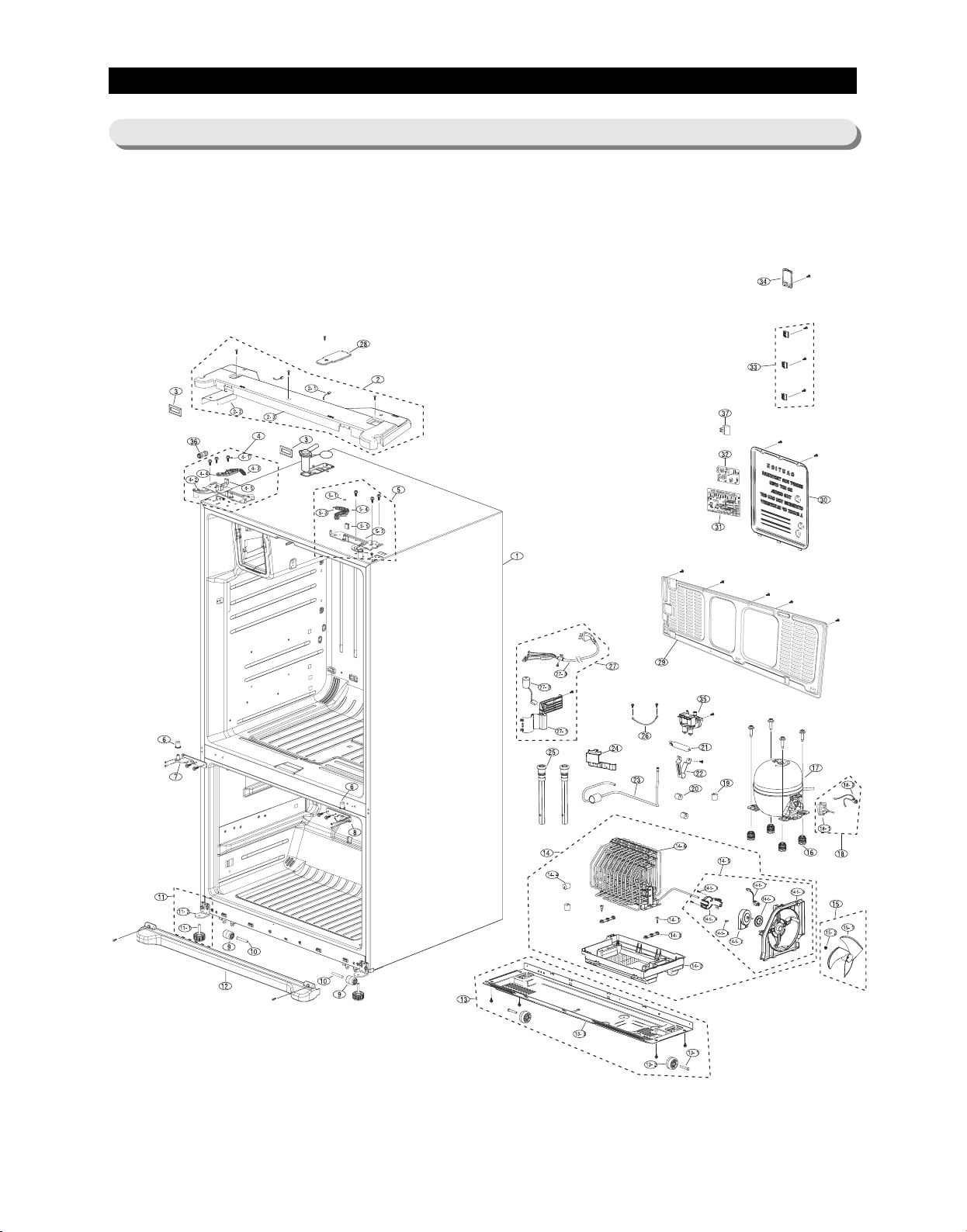
EXPLODED VIEW& PARTS LIST
5-3) Cabinet
38
91
Page 93
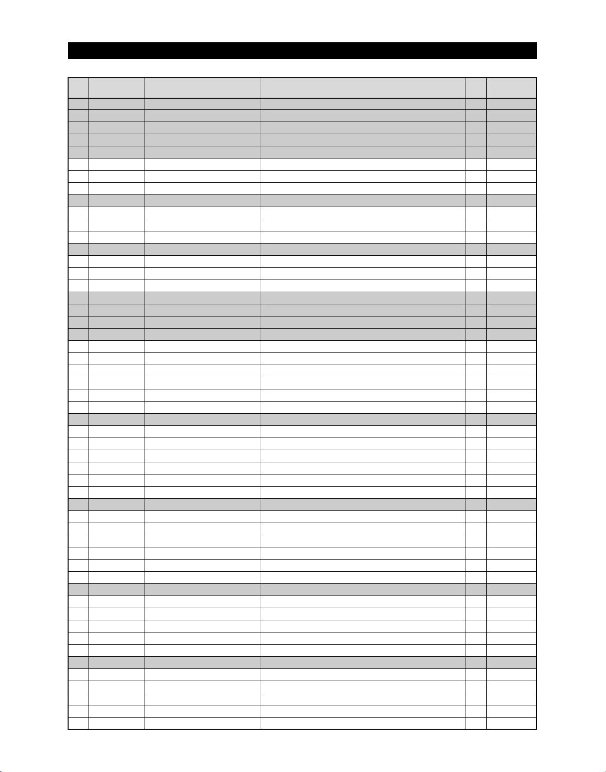
EXPLODED VIEW& PARTS LIST
■■
Parts List of Cabinet
NNOO CCOODDEE--NNOO RREEMMAARRKKPPAARRTT NNAAMMEE SSPPEECC
1
DA90-03870A
1
DA90-03870B
1
DA90-03870C
1
DA90-03870E
2
DA97-05390A
2-1
DA34-00043B
2-2
DA61-04051A
2-3
DA64-02256A
2
DA97-05390B
2-1
DA34-00043B
2-2
DA61-03678A
2-3
DA64-02256B
2
DA97-05390C
2-1
DA34-00043B
2-2
DA61-03678A
2-3
DA64-02256C
3
DA67-01613A
3
DA67-01613B
3
DA67-01613C
4
DA97-04874H
4-1
DA60-00162A
4-2
DA61-03239A
4-3
DA61-03301B
4-4
DA97-04903A
4-5
DA63-03673A
4-6
DA61-03677A
4
DA97-04874J
4-1
DA60-00162A
4-2
DA61-03239A
4-3
DA61-03301B
4-4
DA97-04903B
4-5
DA63-03673A
4-6
DA61-03677A
4
DA97-04874K
4-1
DA60-00162A
4-2
DA61-03239A
4-3
DA61-03301B
4-4
DA97-04903C
4-5
DA63-03673A
4-6
DA61-03677A
5
DA97-04875A
5-1
DA60-00162A
5-2
DA61-03240A
5-3
DA61-03301A
5-4
DA97-04903A
5-5
DA63-03673A
5
DA97-04875B
5-1
DA60-00162A
5-2
DA61-03240A
5-3
DA61-03301A
5-4
DA97-04903B
5-5
DA63-03673A
ASSY CABINET FORM
ASSY CABINET FORM
ASSY CABINET FORM
ASSY CABINET FORM
ASSY-TOP TABLE
SWITCH REED-ASS'Y
PLATE-TOP TABLE
TOP TABLE
ASSY-TOP TABLE
SWITCH REED-ASS'Y
PLATE-TOP TABLE
TOP TABLE
ASSY-TOP TABLE
SWITCH REED-ASS'Y
PLATE-TOP TABLE
TOP TABLE
CAP-TOP TABLE
CAP-TOP TABLE
CAP-TOP TABLE
ASSY HINGE UPP-L
FASTENER-RING
HINGE-UPP L
SPRING ETC-AUTO CLOSE
ASSY LEVER-AUTO CLOSE
GROMMET-LEVER
FIXER WATER PIPE HINGE
ASSY HINGE UPP-L
FASTENER-RING
HINGE-UPP L
SPRING ETC-AUTO CLOSE
ASSY LEVER-AUTO CLOSE
GROMMET-LEVER
FIXER WATER PIPE HINGE
ASSY HINGE UPP-L
FASTENER-RING
HINGE-UPP L
SPRING ETC-AUTO CLOSE
ASSY LEVER-AUTO CLOSE
GROMMET-LEVER
FIXER WATER PIPE HINGE
ASSY HINGE UPP-R
FASTENER-RING
HINGE-UPP R
SPRING ETC-AUTO CLOSE
ASSY LEVER-AUTO CLOSE
GROMMET-LEVER
ASSY HINGE UPP-R
FASTENER-RING
HINGE-UPP R
SPRING ETC-AUTO CLOSE
ASSY LEVER-AUTO CLOSE
GROMMET-LEVER
AW-PJT,BLACK
AW-PJT,REAL-STS
AW-PJT,SNOW-WHITE
RF26VABSH,-,PLATINUM STS,115/60
AW-PJT,HIPS,I-BLACK(SC-00477R)
200VDC,1.5A,
AW-PJT,SBHG1,T0.3,65.5,107,-,AW-BESTÄ
AW-PJT,ABS(VH0815),I-BLACK(SC-00477R)
AW-PJT,HIPS,Creamy STS(SC-07009R)
200VDC,1.5A,
AW-PJT,SBHG1,T0.3,
AW-PJT,ABS(VH0815),Creamy STS(SC-07009R)
AW-PJT,HIPS,Snow-White(SC-97527R)
200VDC,1.5A,
AW-PJT,SBHG1,T0.3,
AW-PJT,ABS(VH0815),Snow-White(SC-97527R)
AW-PJT,ABS,I-BLACK(SC-00477R)
AW-PJT,ABS,Creamy STS(SC-07009R)
AW-PJT,ABS,Snow-White(SC-97527R)
AW-PJT,T2.9,BLACK
AW-PJT,STS304,ID5,T0.5,OD11,BLACK,
AW-PJT,SHP1,T2.9,
AW-PJT,STS304,1.4,9.2,12,20
AW-PJT,POM,i-BLACK
AW-PJT,NBR,BLACK
AW-PJT,SHP1,T1.2
AW-PJT,T2.9,Creamy-STS
AW-PJT,STS304,ID5,T0.5,OD11,BLACK,
AW-PJT,SHP1,T2.9,
AW-PJT,STS304,1.4,9.2,12,20
AW-PJT,POM,Creamy-STS
AW-PJT,NBR,BLACK
AW-PJT,T2.9,Snow-White
AW-PJT,STS304,ID5,T0.5,OD11,BLACK,
AW-PJT,SHP1,T2.9,
AW-PJT,STS304,1.4,9.2,12,20
AW-PJT,POM,Snow-White
AW-PJT,NBR,BLACK
AW-PJT,T2.9,i-BLACK
AW-PJT,STS304,ID5,T0.5,OD11,BLACK,
AW-PJT,SHP1,T2.9,
AW-PJT,STS604,1.4,9.2,12,24,
AW-PJT,POM,i-BLACK
AW-PJT,NBR,BLACK
AW-PJT,T2.9,Creamy-STS
AW-PJT,STS304,ID5,T0.5,OD11,BLACK,
AW-PJT,SHP1,T2.9,
AW-PJT,STS604,1.4,9.2,12,24,
AW-PJT,POM,Creamy-STS
AW-PJT,NBR,BLACK
92
QQUUAANN
TTIITTYY
1
1
1
1
1
2
1
1
1
2
1
1
1
2
1
1
2
2
2
1
1
1
1
1
1
1
1
1
1
1
1
1
1
1
1
1
1
1
1
1
1
1
1
1
1
1
1
1
1
1
1
Page 94
EXPLODED VIEW& PARTS LIST
■■
Parts List of Cabinet
NNOO
CCOODDEE--NNOO RREEMMAARRKKPPAARRTT NNAAMMEE SSPPEECC
5
DA97-04875C
5-1
DA60-00162A
5-2
DA61-03240A
5-3
DA61-03301A
5-4
DA97-04903C
5-5
DA63-03673A
6
DA63-02905A
7
DA97-04876B
8
DA97-04877B
9
DA61-40115B
10
DA61-01920A
11
DA97-05016A
11-1
DA61-00805C
11-2
DA61-03217A
12
DA63-03434A
12
DA63-03434B
12
DA63-03434C
13
DA97-02064B
13-1
DA60-90146A
13-2
DA61-40126B
13-3
DA64-01170A
14
DA97-05043B
14-1
6009-001252
14-2
DA63-03450A
14-3
DA63-40128A
14-4
DA63-40171B
14-5
DA97-03145K
14-5-1
6003-000003
14-5-2
DA31-00146D
14-5-3
DA61-02349B
14-5-4
DA61-02355B
14-5-5
DA63-01146A
14-5-6
DA63-40167A
14-5-7
DA96-00042A
14-6
DA97-05093A
15
DA31-00010D
15-1
DA31-00015C
15-2
DA61-20128A
16
DA63-02017A
MK172DR2U/E09
17
DA97-02895K
18
DA96-00174E
18-1
DA35-00008X
18-2
DA35-00103B
18-3
DA63-40171B
19
DA63-40171D
20
DA62-01514A
21
DA61-02657A
22
DA97-06085A
23
DA61-02434A
24
DA97-04049A
25
DA39-20389L
26
ASSY HINGE UPP-R
FASTENER-RING
HINGE-UPP R
SPRING ETC-AUTO CLOSE
ASSY LEVER-AUTO CLOSE
GROMMET-LEVER
GROMMET HINGE-MID,R
ASSY HINGE MID-L
ASSY HINGE MID-R
CASTER-FRONT
CASTER-RIVET
ASSY-SUPPORT FOOT FRONT
FOOT-FRONT
SUPPORT-FOOT FRONT
COVER-LEG FRONT
COVER-LEG FRONT
COVER-LEG FRONT
ASSY CHASSIS-COMP
PIN-CASTER
CASTER-REAR
CHASSIS COMP
ASSY TRAY-DRAIN WATER
SCREW-SPECIAL
TRAY-DRAIN WATER
GROMMET-SUB COND
GROMMET-SUCT PIPE A
ASSY SUPPORT-CIRCUIT MOTOR
SCREW-TAPTITE
MOTOR BLDC
SUPPORT-CIRCUIT MOTOR
BRACKET-CIRCUIT MOTOR
GROMMET-MOTOR,REAR
GROMMET-COVER CHIL
ASSY-HARNESS MOTOR
ASSY PIPE-SPIRAL COND
FAN-ASS'Y
FAN-TURBO
SPRING ETC-FAN
GROMMET-COMP
COMPRESSOR
ASSY-COMP SUB
ASSY-HARNESS COMP
RELAY PROTECTOR O/L
RELAY-PTC THERMISOR
GROMMET-SUCT PIPE A
GROMMET-SUCT PIPE B
DRYER
CLIP-DRYER
ASSY PIPE CONNECT-SUCTION
FIXER-HOSE(VALVE)
ASSY CAP-DRAIN
WIRE HARNESS-EARTH
QQUUAANN
TTIITTYY
AW-PJT,T2.9,Snow-White
AW-PJT,STS304,ID5,T0.5,OD11,BLACK,
AW-PJT,SHP1,T2.9,
AW-PJT,STS604,1.4,9.2,12,24,
AW-PJT,POM,Snow-White
AW-PJT,NBR,BLACK
NEXT,POM,T2.0,WHITE,
AW-PJT,T4.5,Ni-Cr
AW-PJT,T4.5,Ni-Cr
SR-50,PP
(ZPC2),MSWR10,OD8.0,L54
AW-PJT
AW-PJT,PP
AW-PJT,SHP1,T4.0,BLACK
AW-PJT,PP,i-BLACK
AW-PJT,PP,Creamy-STS
AW-PJT,PP,Snow-White
AD,NEXT,SBHG1,T1.4,
MSWR10,OD6.0,L40,ZPC2,SR2894
REFALL,PP,PI 44,NTR,W22,
AD,SBHG1,T1.4,
AW-PJT,
PH,+,M4.0,L20(12),ZPC(WHT),SWRCH18A
AW-PJT,PP,NTR,
,NBR,DARKGRAY
,NBR,OD20,ID4,L20,BLK
NEXT,
BH,+,B,M4,L10,ZPC(BLK),SWRCH18A,
,1500,DC12V,250mA,2.5W,MOTORBLDC,
NEXT,ABS,NTR,
ABS,NEXT,NTR
A-TOP,NBR,ID6.5,OD42,BLK,BLDCÄ
T3.0,SILICON,NTR
ATOP UL(MOTOR),CFAN,350MM
AW-PJT,
,ET,ZIPEL,ASSY,UNIT,?150
,ET-PJT,ABS+GLASS FIBE,GR4010
,STS304,PI7.8,OD1.0,FD
QUEEN,EPDM,
115-127V~60HZ,RSCR,FAN
AW-PJT
AW-PJT(GE-OEM),AWG #18
2000S501,4TM435RFBYY,S/T:16.5A,U//T:4.28A,135,61
PTHTM100MD3
,NBR,OD20,ID4,L20,BLK
RAIL L19.5,NR,OD20,ID6,BLK
REF-ALL,C1220T,OD18.70,L114
AD,SECC1,T0.4,
aw,c1220 t
ET'05-PJT,PP,T2
EPEL,ASSY,L224.5,SOFTPVC
GREEN/YEL,UL 1015 AWG18,150mm
93
1
1
1
1
1
1
2
1
1
1
1
2
1
1
1
1
1
1
2
2
1
1
2
1
2
2
1
2
1
1
1
1
1
1
1
1
1
1
4
1
1
1
1
1
2
1
1
1
1
2
1
Page 95
EXPLODED VIEW& PARTS LIST
■
Parts List of Cabinet
NO
CODE-NO SVC-CODE REMARKPART N AME SPEC
DA97-05147A
27
DA63-02907A
27-1
DA27-00009B
27-2
DA39-10165E
27-3
DA97-05363B
28
DA97-06321A
29
DA97-05031B
30
DA41-00413J
31
DA41-00413M
DA41-00320A
32
DA61-02434A
33
DA63-00586B
34
DA62-00914B
35
DA62-01627B
36
37
2301-001837
38
DA97-05362B
ASSY-COVER NOISE FILTER
COVER-NOISE FILTER
COIL CHOKE-EMI FILTER
CBF-POWER CORD
ASSY-COVER PIPE WATER
ASSY COVER-COMP
ASSY-COVER PCB PANEL
PBA MAIN-BEST
PBA MAIN
PBA SMPS-NEXT
FIXER-HOSE
COVER-TUBE FILTER
VALVE-WATER FITTING
TUBE-FITTING-B
C-FILM LEAD
ASSY-PIPE WATER
AW-PJT
NEXT,PP,NFPP
FA2107LB,QUEEN GE,5mH,+50%,30%,10A,38*50
ET-PJT,SVT-3,125V,15A,L=2300,BLACK,UL
AW-PJT
AW-PJT
AW-PJT,
AW-PJT,ASSY CYCLE,FR-4,163*197,BEST,+12V,+5V,60Hz
AW-PJT,ASSY CYCLE,FR-4,163*197,
NEXT,TOP,CEM1,148*100,POWER SUPPLY,85~170V,50~60Hz
ET05,PP,T2
A-TOP,W76,L83
12A-41,110~127V
POM,CAP FITTING ADD
250V
AW-PJT(BEST)
QUAN
TITY
1
1
1
1
1
1
1
1
1
1
3
1
1
1
1
1
RF267AB*/XAA
RF267AB*/XAC
94
Page 96
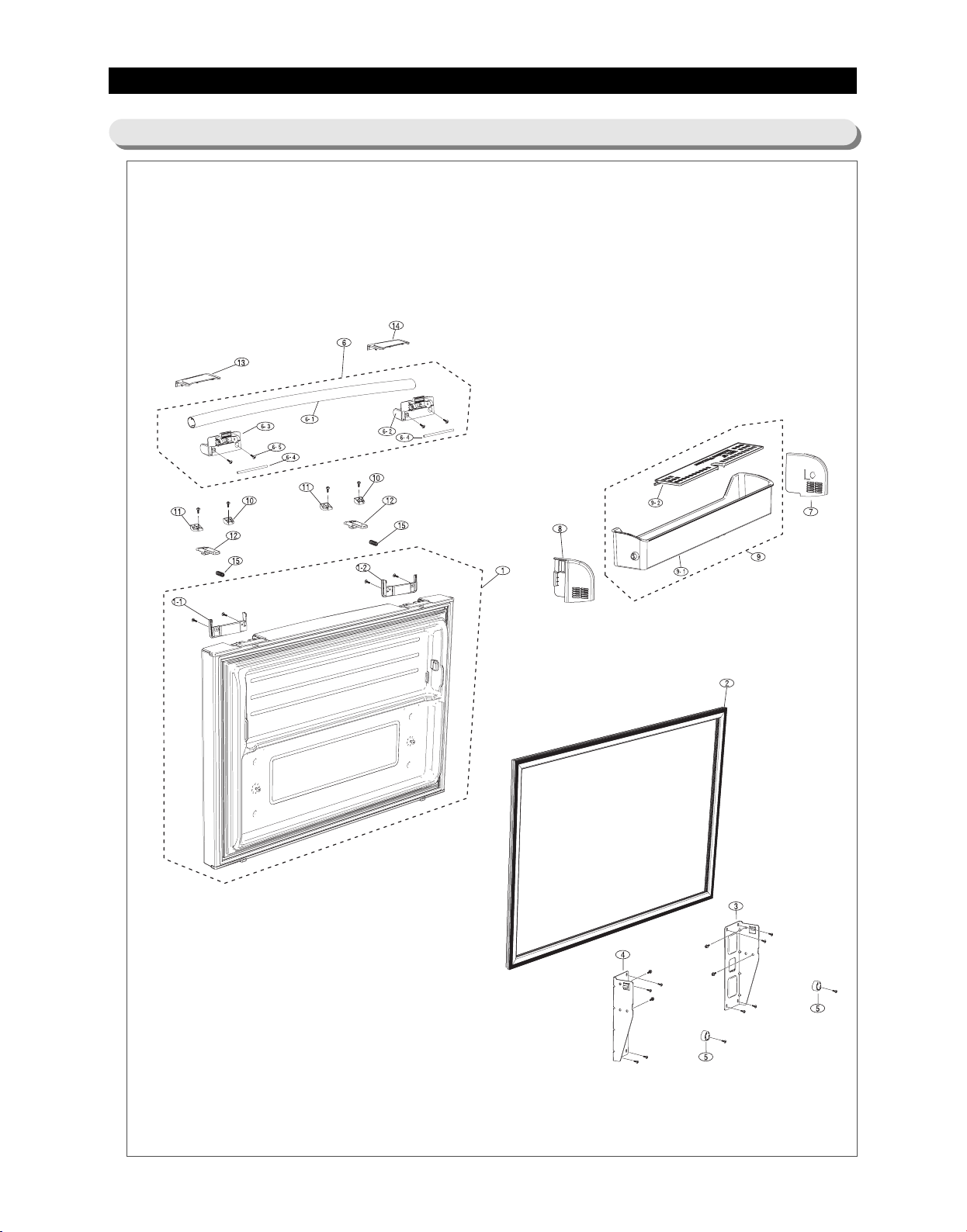
EXPLODED VIEW& PARTS LIST
5-4) Disassembly of Freeze Door
95
Page 97
EXPLODED VIEW& PARTS LIST
■■
Parts List of Freezer Door
NNOO
CCOODDEE--NNOO
1
DA90-04554A
1
DA90-04554B
1
DA90-04554C
1
DA90-04554D
1-1
DA67-01992A
1-1
DA67-01992B
1-1
DA67-01992C
1-2
DA67-01993A
1-2
DA67-01993B
1-2
DA67-01993C
2
DA97-05557B
3
DA61-03153B
4
DA61-03155B
5
DA61-02904B
6
DA97-06429A
6-1
DA64-02527A
6-2
DA67-01995A
6-3
DA67-01996A
6-4
DA66-00579A
6-5
6002-000215
6
DA97-06429B
6-1
DA64-02527B
6-2
DA67-01995B
6-3
DA67-01996B
6-4
DA66-00579A
6-5
6002-000215
6
DA97-06429C
6-1
DA64-02527C
6-2
DA67-01995C
6-3
DA67-01996C
6-4
DA66-00579A
6-5
6002-000215
6
DA97-06429D
6-1
DA64-02527D
6-2
DA67-01995B
6-3
DA67-01996B
6-4
DA66-00579A
6-5
6002-000215
7
DA61-03762A
8
DA61-03763A
9
DA97-04880A
9-1
DA63-03458A
9-2
DA63-03459A
10
DA61-04254A
11
DA61-04255A
12
DA61-04258A
13
DA63-04247A
13
DA63-04247B
13
DA63-04247C
14
DA63-04248A
14
DA63-04248B
14
DA63-04248C
ASSY DOOR FOAM FRE
ASSY DOOR FOAM FRE
ASSY DOOR FOAM FRE
ASSY DOOR FOAM FRE
CAP DOOR-FRE SUB L
CAP DOOR-FRE SUB L
CAP DOOR-FRE SUB L
CAP DOOR-FRE SUB R
CAP DOOR-FRE SUB R
CAP DOOR-FRE SUB R
ASSY-GASKET DOOR FRE
HANGER-RAIL FRONT L
HANGER-RAIL FRONT R
SUPPORT DOOR POSITION IN
ASSY HANDLE-BAR FRE(EASY)
HANDLE-BAR FRE
CAP-HANDLE FRE L
CAP-HANDLE FRE R
SHAFT-CAP HANDLE
SCREW-TAPPING
ASSY HANDLE-BAR FRE(EASY)
HANDLE-BAR FRE
CAP-HANDLE FRE L
CAP-HANDLE FRE R
SHAFT-CAP HANDLE
SCREW-TAPPING
ASSY HANDLE-BAR FRE(EASY)
HANDLE-BAR FRE
CAP-HANDLE FRE L
CAP-HANDLE FRE R
SHAFT-CAP HANDLE
SCREW-TAPPING
ASSY HANDLE-BAR FRE(EASY)
HANDLE-BAR FRE
CAP-HANDLE FRE L
CAP-HANDLE FRE R
SHAFT-CAP HANDLE
SCREW-TAPPING
SUPPORT-GUARD FRE L
SUPPORT-GUARD FRE R
ASSY GUARD FRE
GUARD-FRE
GUARD-FRE FLIP
FIXER-SHAFT HANDLE L
FIXER-SHAFT HANDLE R
SLIDER-HANDLE FRE
COVER-HANDLE FRE L
COVER-HANDLE FRE L
COVER-HANDLE FRE L
COVER-HANDLE FRE R
COVER-HANDLE FRE R
COVER-HANDLE FRE R
SSPPEECC
AW-PJT,EMPIRE-BLACK
AW-PJT,VERSAILLES-STS,
AW-PJT,SNOW-WHITE
AW-PJT,PLATINUM-INOX
AW-PJT,ABS,I-BLACK,EASY-HANDLE
AW-PJT,ABS,CREAMY-STS,EASY-HANDLE
AW-PJT,ABS,Snow-White,EASY-HANDLE
AW-PJT,ABS,I-BLACK,EASY-HANDLE
AW-PJT,ABS,CREAMY-STS,EASY-HANDLE
AW-PJT,ABS,Snow-White,EASY-HANDLE
AW-PJT,GRAY,TD-SECT
AW,SECC1,T2.0,COOL-WHITE
AW-PJT,SECC1,T2.0,COOL-WHITE
AW-PJT,HIPS,NTR
AW-PJT,MATURE BLACK
AW-PJT,AL,MATURE-BLACK,EASY-HANDLE
AW-PJT,PC,i-BLACK,EASY-HANDLE
AW-PJT,PC,i-BLACK,EASY-HANDLE
AW-PJT,MSWR10,108,5,ZPC3(Y)
TH,+,-,1,M4.0,L16,ZPC(WHT),SWRCH18A,
AW-PJT,Versailles-STS,Versailles-Silver
AW-PJT,AL,Versailles-Silver,EASY-HANDLE
AW-PJT,PC,Versailles-Stainless,EASY-HANDLE
AW-PJT,PC,Versailles-Stainless,EASY-HANDLE
AW-PJT,MSWR10,108,5,ZPC3(Y)
TH,+,-,1,M4.0,L16,ZPC(WHT),SWRCH18A,
AW-PJT,SNOW WHITE
AW-PJT,AL,Snow-White,EASY-HANDLE
AW-PJT,PC,Snow-White,EASY-HANDLE
AW-PJT,PC,Snow-White,EASY-HANDLE
AW-PJT,MSWR10,108,5,ZPC3(Y)
TH,+,-,1,M4.0,L16,ZPC(WHT),SWRCH18A,
AW-PJT,NEW VERSAILLES SILVER,SANDING
AW-PJT,AL,Versailles-Silver(sanding),EASY-HANDLE
AW-PJT,PC,Versailles-Stainless,EASY-HANDLE
AW-PJT,PC,Versailles-Stainless,EASY-HANDLE
AW-PJT,MSWR10,108,5,ZPC3(Y)
TH,+,-,1,M4.0,L16,ZPC(WHT),SWRCH18A,
AW-PJT(BEST),HIPS(HG-1760SF),COOL-WHITE
AW-PJT(BEST),HIPS(HG-1760SF),COOL-WHITE
AW-PJT,COOL-WHT
AW-PJT,HIPS(HR1360),COOL-WHITE
AW-PJT,HIPS(HR1360),COOL-WHITE
AW-PJT,POM,-,NTR,EASY-HANDLE
AW-PJT,POM,-,NTR,EASY-HANDLE
AW-PJT,POM,EASY-HANDLE
AW-PJT,ABS,I-BLACK,EASY-HANDLE
AW-PJT,ABS,CREAMY-STS,EASY-HANDLE
AW-PJT,ABS,Snow-White,EASY-HANDLE
AW-PJT,ABS,I-BLACK,EASY-HANDLE
AW-PJT,ABS,CREAMY-STS,EASY-HANDLE
AW-PJT,ABS,Snow-White,EASY-HANDLE
96
QQUUAANN
TTIITTYY
1
1
1
1
1
1
1
1
1
1
1
1
1
2
1
1
1
1
2
4
1
1
1
1
2
4
1
1
1
1
2
4
1
1
1
1
2
4
1
1
1
1
1
2
2
2
1
1
1
1
1
1
RREEMMAARRKKPPAARRTT NNAAMMEE
Page 98
EXPLODED VIEW& PARTS LIST
■■
Parts List of Freezer Door
NNOO
CCOODDEE--NNOO
15 2
DA61-04335A
SPRING ETC-EASY HANDLE
08 AW1,2-PJT,HSWR
SSPPEECC
QQUUAANN
TTIITTYY
RREEMMAARRKKPPAARRTT NNAAMMEE
97
Page 99
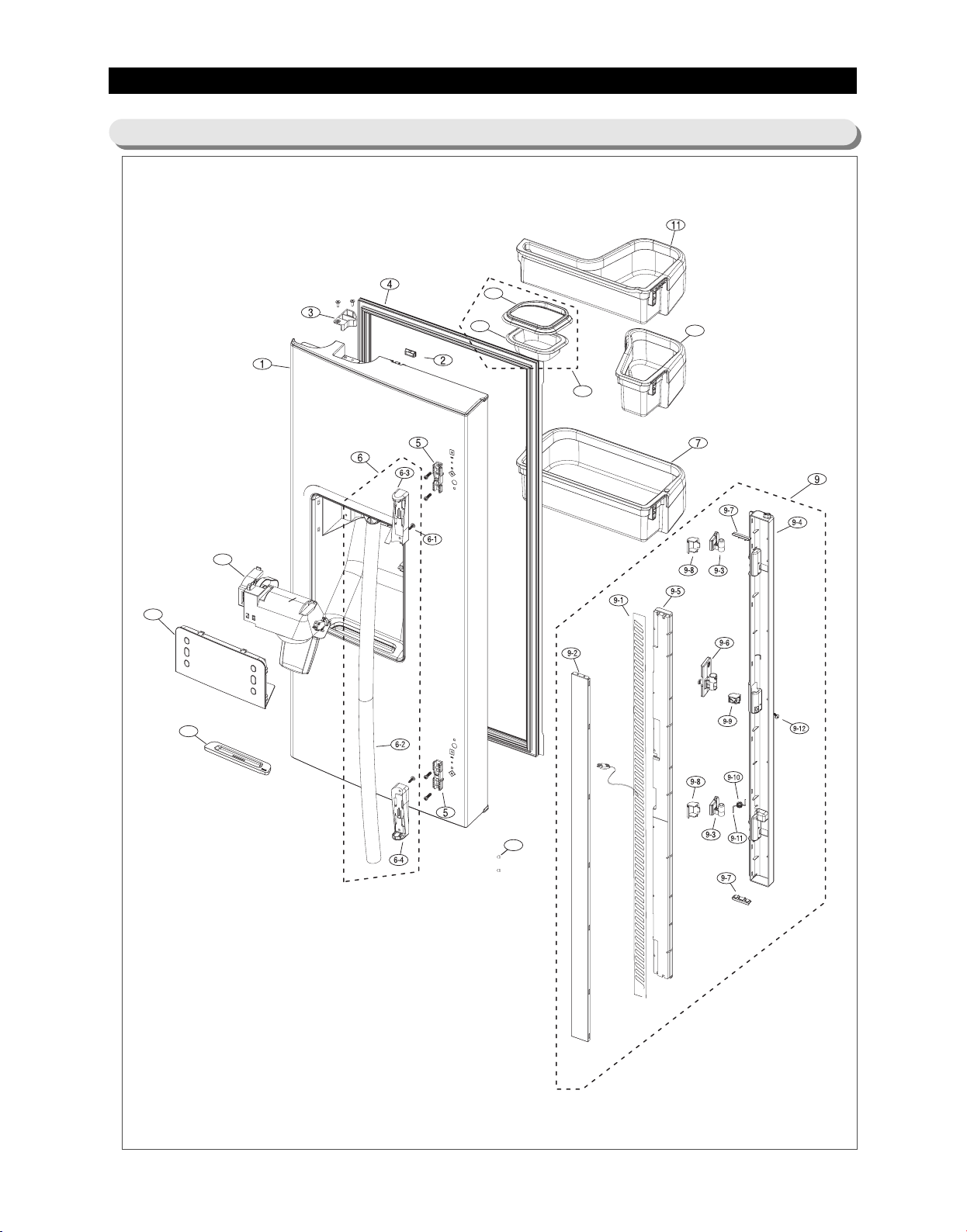
EXPLODED VIEW& PARTS LIST
8
12
12-1
12-2
14
13
15
10
5-5) Disassembly of Refrigerator DoorLeft
98
Page 100
EXPLODED VIEW& PARTS LIST
■■
Parts List of Refrigerator Door-Left
NNOO
CCOODDEE--NNOO RREEMMAARRKKPPAARRTT NNAAMMEE
DA91-02544A
1
DA91-02544B
1
DA91-02544C
1
DA91-02544D
1
DA61-02738E
2
DA61-02738F
2
DA61-02738A
2
DA66-00442A
3
DA66-00442B
3
DA66-00442C
3
DA97-05253A
4
DA97-05253B
4
DA97-05253B
4
DA61-02984A
5
DA97-04417N
6
6002-000215
6-1
DA64-01979A
6-2
DA67-01527E
6-3
DA67-01528E
6-4
DA97-04417J
6
6002-000215
6-1
DA64-01979E
6-2
DA67-01527F
6-3
DA67-01528F
6-4
DA97-04417D
6
6002-000215
6-1
DA64-01979D
6-2
DA67-01527D
6-3
DA67-01528D
6-4
DA97-04417K
6
6002-000215
6-1
DA64-01979B
6-2
DA67-01527F
6-3
DA67-01528F
6-4
DA97-04878C
7
DA97-05241A
8
DA97-05021N
9
DA47-00245C
9-1
DA61-03207A
9-2
DA61-03230B
9-3
DA61-03234A
9-4
DA62-01387A
9-5
DA63-03454B
9-6
DA63-03508A
9-7
DA67-01650A
9-8
DA67-01701A
9-9
DA81-01345A
9-10
DA81-01346A
9-11
6002-000213
9-12
DA97-05021P
9
DA47-00245C
9-1
DA61-03207B
9-2
ASSY DOOR FOAM REF-L
ASSY DOOR FOAM REF L
ASSY DOOR FOAM REF L
ASSY DOOR FOAM REF L
MAGNET-ASS'Y
MAGNET-ASS'Y
MAGNET-ASS'Y
CAM AUTO CLOSE L
CAM AUTO CLOSE L
CAM AUTO CLOSE L
ASSY-GASKET DOOR REF
ASSY-GASKET DOOR REF
ASSY-GASKET DOOR REF
FIXER-HANDLE
ASSY HANDLE-BAR
SCREW-TAPPING
HANDLE BAR
CAP-HANDLE UPP
CAP-HANDLE LOW
ASSY HANDLE-BAR
SCREW-TAPPING
HANDLE BAR
CAP-HANDLE UPP
CAP-HANDLE LOW
ASSY HANDLE-BAR
SCREW-TAPPING
HANDLE BAR
CAP-HANDLE UPP
CAP-HANDLE LOW
ASSY HANDLE-BAR
SCREW-TAPPING
HANDLE BAR
CAP-HANDLE UPP
CAP-HANDLE LOW
ASSY GUARD REF
ASSY-GUARD_REF_MID
ASSY-FRENCH
HEATER CORD-FRENCH
PLATE-FRENCH
HINGE-FRENCH
CASE-FRENCH
INSULATION-FRENCH
COVER-HEATER FRENCH
GASKET-FRENCH
CAP-CASE FRENCH
CAP-CASE FRENCH MID
SPRING-ETC FRENCH
PIN-FRENCH SPRING
SCREW TAPPING
ASSY-FRENCH
HEATER CORD-FRENCH
PLATE-FRENCH
SSPPEECC
AW-PJT,BLACK
AW-PJT,REAL-STS
AW-PJT,SNOW-WHITE
AW-PJT,PLATINUM-STS
CORE-PJT,T5,W7,L18,i-BLACK
CORE-PJT,T5,W7,L18,Creamy-gray
CORE-PJT,T5,W7,L18,Snow-White
AW-PJT,Nylon6,i-BLACK
AW-PJT,Nylon6,Creamy-STS
AW-PJT,Nylon6,Snow-White
AW-PJT,W404,L978,BLACK
AW-PJT,W404,L978,GRAY
AW-PJT,W404,L978,WHITE
ATOP 06,POM,NTR,
ATOP 06,MATURE-BLACK,i-BLACK
TH,+,1,M4.0,L16,ZPC(WHT),SWRCH18A
ATOP 06,AL(A6063),MATURE-BLACK
ATOP06,ABS(HG0760),i-BLACK
ATOP06,ABS(HG0760),i-BLACK
ATOP06,,Versailles-STS,Versailles-Silver
TH,+,1,M4.0,L16,ZPC(WHT),SWRCH18A
ATOP 06,AL(A6063),Versailles-STS(STRIPE HAIRLINE)
ATOP06,ABS(HG0760),Versailles-Silver
ATOP06,ABS(HG0760),Versailles-Silver
ATOP 06,Snow-White
TH,+,1,M4.0,L16,ZPC(WHT),SWRCH18A
ATOP 06,AL(A6063),Snow-White
ATOP06,ABS(HG0760),Snow-White
ATOP06,ABS(HG0760),Snow-White
ATOP-06,Versailles-STS,Platinum-STS(SANDING)
TH,+,1,M4.0,L16,ZPC(WHT),SWRCH18A
ATOP-06,AL(A6063),Versailles-STS
ATOP06,ABS(HG0760),Versailles-STS(SANDING)
ATOP06,ABS(HG0760),Versailles-STS(SANDING)
AW-PJT,PP(BJ730),COOL-WHITE(SC02740R)
AW-PJT,HIPS+GPPS,-,99,185,COOL-WHT,BEST,MIDÄ
AW-PJT,8W,Black,AW08_BEST
AW-PJT,P-CORD,8W,115V,1653Ω,FRENCH
AW-PJT,SECC1,T0.8,ALL-BLACK
AW-PJT,PC(HF-1023IM),COOL-WHITE
AW-PJT,ABS,SNOW-WHITE
AW-PJT,FOAMPS
AW-PJT,PC(HF-1023IM),COOL-WHITE
AW-PJT,SILICON,BLACK
AW-PJT,ABS,SNOW-WHITE
AW-PJT,ABS,SNOW-WHITE
STS304,PI1.4
RDPVC,WHITE
TH,+,-,1,M4,L12,ZPC(WHT),SWRCH18A
AW-PJT,8W,Thai Silver,AW08_BEST
AW-PJT,P-CORD,8W,115V,1653Ω,FRENCH
AW-PJT,SECC1,T0.8
99
QQUUAANN
TTIITTYY
1
1
1
1
1
1
1
1
1
1
1
1
1
2
1
2
1
1
1
1
2
1
1
1
1
2
1
1
1
1
2
1
1
1
1
1
1
1
1
2
1
1
1
2
2
1
1
1
1
1
1
 Loading...