

Page 1
IMPORTANT SAFETY NOTICE – ―For Technicians Only‖ This service data sheet is
Component Resistance Wattage Voltage
Freezer Defrost Heater 60Ω 240 120vac
Fridge Defrost Heater 120Ω 120 120vac
French Mullion Heater 1323Ω 10 120vac
Fill Tube Heater 1323Ω 10 120vac
Sensors 2.5kΩ-89kΩ N/A 1~4.5vdc
Fans N/A N/A 7~12vdc
# tsRF263AE RevA 11/24/2010
1
Models Covered:
RF263AEBP/XAA
RF263AEPN/XAA
RF263AERS/XAA
RF263AEWP/XAA
French Door Refrigeration
intended for use by persons having electrical, electronic, and mechanical experience
and knowledge at a level generally considered acceptable in the appliance repair trade.
Any attempt to repair a major appliance may result in personal injury and property
damage. The manufacturer or seller cannot be responsible, nor assume any liability for
injury or damage of any kind arising from the use of this data sheet.
Fast Track Troubleshooting
Publication # tsRF263AE Revision Date 11/24/2010
NOTICE:
RF263AE**
11/10
Parts Change:
Refer to bulletin.
All Handles
Press Freezer button one
time at the Test Mode to
Force Compressor High
Speed Run, measure fan
and Compressor voltages at main PCB
Sealed System
Self Diagnosis: Press the Pwr Freeze—Pwr
Cool buttons simultaneously for 8-12 seconds
(No sound when both buttons are pressed at
the same time) until the display quits blinking.
Release the buttons and read Fault Codes.
This will also cancel the Fault Mode created by
self-diagnosis at power up.
Press Freezer button a
second time to Force
Mid Speed Run
Refrigerant Charge
R134a 5.64 oz.
Forced Mode: Press the Pwr Freeze– Fridge
buttons simultaneously for 8-12 seconds
(No sound when both buttons are pressed
at the same time) until the display beeps
and goes blank.
Press Freezer button a
third time to Force Low
Speed Run
Sales Mode, No Compressor Operation
Press Power Freeze & Freezer temp buttons
simultaneously for 3 sec ( you will hear a ―Ding
Dong‖) to remove or put into Sales Mode. When
in the Sales Mode the Display will show "OF" "OF"
Press Freezer button a
forth time to Force Defrost of Fridge & Freezer,
measure defrost voltage
at main PCB
Training — Plus One http://my.plus1solutions.net/clientPortals/samsung/
Help — GSPN http://service.samsungportal.com/
Removing power will not cancel this mode.
Component Value Chart
SUPPORT INFORMATION
Page 2
DC FAN MOTORS
# tsRF263AE RevA 11/24/2010
2
Brushless DC Fan motors are used to save energy. The fans operate at two speeds. Fan speed information is read by
the Main PCB. If the fan speed exceeds 600 RPM or the speed is too slow, or stopped the fan drive circuit is disabled,
After 10 seconds the circuit tries again with 3 seconds of DC voltage. If the fan continues this activity for 5 cycles, 10
seconds off 3 seconds on, the fan drive circuit is disabled for 10 minutes.
TO TEST THE FAN CIRCUIT VOLTAGE.
Power off and back on to check the DC voltage to the motor, wait from 10 to 60 seconds for the fan voltage to kick in,
and then check fan voltage, the average reading is 9 VDC. If you get 3 seconds of voltage every 10 seconds for the 5
fan power up cycles, then the Main PCB is good.
NOTE: You may need to put unit in FORCED FREEZE mode to activate the fans/compressor.
If the fan blade is blocked by ice, then defrost and check the motor again, after removing power from the unit.
If the evaporator is ice blocked and thus blocking the air flow, the fan will over RPM and will be stopped. Remove ice
and check the motor again. If everything is clear around the fan blade then the motor would be at fault. Continuous fan
errors will be displayed on the front panel display. PLEASE NOTE: The door switches control the evaporator fan motors. Have them closed to test the motors. Delay time 10 – 60 seconds.
FLEX TRAY Ice Makers
When the initial power is applied, the ice tray will stand by for 2
hours. After the 2-hour standby time, the Ice Maker Sensor will check
the temperature , when it is lower than 1.5℉ for more than 5 minutes,
it will do a harvest, with or without ice in the tray, then fill with water.
58 minutes after water is supplied to the Ice Tray, the Ice Maker
Sensor temperature will be checked. When the Ice Maker Sensor
maintains lower than 1.5℉ for 5 minutes, it completes the harvest
(if the ice bin is not sensed as full).
Filling the tray
After the water fill is completed, the ice maker sensor will evaluate the
water volume one and a half minutes later. When it detects no or low
water level, it will add more water. First supply time will be 1.5 sec,
next one will be 1 sec and the last will be 2 sec.
When all ice shatters, it's because of a bad tray
or ice cube temp that is too cold (lower than -5
degrees). In some areas, there are water issues
that can also cause shattered cubes. The temp
in the freezer should not have any effect on this
issue, as long as it’s below 1.5 degrees F, as a
properly installed sensor will not read the
freezer temp, only the water/ice temp.
Check the Ice tray for defects in the plastic. Ice
that is too cold will shatter during harvest. This can be from the (1) sensor not reading the correct temp (2) or the sensor not
mounted correctly (3). By programming the ice-
Shattered Ice – Flex Tray
maker offset value to a lower number (4), the
FREEZER TEMPERATURE CONTROL BY THE ICE MAKER
Interior Temperature of the freezer will be set to -14 degrees
Fahrenheit until the ice bucket is full. When the ice bucket is full,
board not understanding the reading.
Please note, some shattering is normal for a
flex tray icemaker.
the freezer will maintain original set temperature. Also, whenever the ice is used, the freezer will again set to -14 degrees
Fahrenheit. Selecting "Ice Off‖ will allow the freezer to be con-
Ice Maker Thermistor
trolled by the set temperature. If water is not hooked up, the
freezer will always be at –14 unless ―Ice Off‖ is selected.
Ice Maker Test Button
Temperature/Resistance/Voltage Chart for Samsung Refrigerators Sensors
Temp. (Ω) Volts Temp. (Ω) Volts Temp. (Ω) Volts Temp. (Ω) Volts
-29.2°F 64227 4.326 1.4°F 28021 3.685 32.0°F 13290 2.853 62.6°F 6771 2.019
-27.4°F 61012 4.296 3.2°F 26760 3.64 33.8°F 12749 2.802 64.4°F 6521 1.974
-25.6°F 57977 4.264 5.0°F 25562 3.594 35.6 °F 12233 2.751 66.2°F 6281 1.929
-23.8°F 55112 4.232 6.8°F 24425 3.548 37.4 °F 11741 2.7 68.0°F 6052 1.885
-22.0°F 52406 4.199 8.6°F 23345 3.501 39.2 °F 11271 2.649 69.8°F 5832 1.842
-20.2°F 49848 4.165 10.4°F 22320 3.453 41.0°F 10823 2.599 71.6°F 5621 1.799
-18.4°F 47431 4.129 12.2°F 21345 3.405 42.8°F 10395 2.548 75.2°F 5225 1.716
-16.6°F 45146 4.093 14.0°F 20418 3.356 44.6°F 9986 2.498 77.0°F 5000 1.675
-14.8°F 42984 4.056 15.8°F 19537 3.307 46.4°F 9596 2.449 78.8°F 4861 1.636
-13.0°F 40938 4.018 17.6°F 18698 3.258 48.2°F 9223 2.399 80.6°F 4690 1.596
-11.2°F 39002 3.98 19.4°F 17901 3.208 50.0°F 8867 2.35 86.0°F 4218 1.483
-9.4°F 37169 3.94 21.2°F 17142 3.158 51.8°F 8526 2.301 87.8°F 4072 1.447
-7.6°F 35433 3.899 23.0°F 16419 3.107 53.6°F 8200 2.253 89.6°F 3933 1.412
-5.8°F 33788 3.858 24.8°F 15731 3.057 55.4°F 7888 2.205 91.4°F 3799 1.377
-4.0°F 32230 3.816 26.6°F 15076 3.006 57.2°F 7590 2.158 95.0°F 3547 1.309
-2.2°F 30752 3.773 28.4°F 14452 2.955 59.0°F 7305 2.111 96.8°F 3428 1.277
-0.4°F 29350 3.729
30.2°F 13857 2.904 60.8°F 7032 2.064 100.4°F 3204 1.213
Page 3
Error Items LED TROUBLE TESTING
I/M-SENSOR (R on
Twin I/M units)
Ice Maker Sensor Error- open or short-circuit, connector failure.
Cause is also a temperature reading > 122°or < -58 ° F
The voltage at MAIN PCB
Sensor between 4.5V~1.0V
R-SENSOR
Refrigerator Room Sensor Error- open or short-circuit, connector
failure. Cause is also a temperature reading > 122°or < -58 ° F.
The voltage at MAIN PCB
Sensor between 4.5V~1.0V
DEFROST SENSOR
OF R ROOM
Ref. Defrost Sensor Error- open or short-circuit, connector failure.
Cause is also a temperature reading > 122°or < -58 ° F
The voltage at MAIN PCB
Sensor between 4.5V~1.0V
R-FAN ERROR
This error indicates the Refrigerator Evap Fan is not spinning at the
correct RPM or the fan feedback line is open.
Fan voltage at MAIN PCB
shall be between 7V~12V
I/M FUNCTION
ERROR(R on Twin I/M)
This error indicates the Ice tray has not returned to level after an ice
harvest. The error is displayed after three failed attempts.
Replace I/M
R-DEFROSTING
ERROR
Refrigerator Room defrost heater- open or short-circuit, connector
failure, or defective temperature fuse/bi-metal. Defrost on over 80
minutes
Disconnect defrost connector
from PCB, check resistance
PANTRY-DAMPERHEATER ERROR
Sensor system in Pantry Room errors
Disconnect heater connector
from PCB, check resistance
PANTRY-SENSOR
ERROR
CR Room Sensor Error- This can be an open or short-circuit, contact
failure. Cause is also a temperature reading > 122°or < -58 ° F.
The voltage of MAIN PCB
Sensor between 4.5V~1.0V
WATER HEATER
ERROR
Error is displayed when the water reservoir tank heater is open or
shorted
Disconnect heater connector
from PCB, check resistance
EXT-SENSOR
Ambient Temp. Sensor Error- open or short-circuit, connector failure.
Cause is also a temperature reading > 122°or < -58 ° F
The voltage at MAIN PCB
Sensor between 4.5V~1.0V
F-SENSOR
Freezer Compartment Sensor Error- open or short-circuit, connector
failure. Cause is also a temperature reading > 122°or < -58 ° F
The voltage at MAIN PCB
Sensor between 4.5V~1.0V
F-DEF-SENSOR
Freezer Room Defrost Sensor Error- open or short-circuit, connector
failure. Cause is also a temperature reading > 122°or < -58 ° F
The voltage at MAIN PCB
Sensor between 4.5V~1.0V
F-FAN ERROR
This error indicates the Freezer Evap. Fan is not spinning at the
correct RPM or the fan feedback line is open.
Fan voltage at MAIN PCB
shall be between 7V~12V
C-FAN ERROR
This error indicates the Condenser Fan is not spinning at the correct
RPM or the fan feedback line is open.
Fan voltage at MAIN PCB
shall be between 7V~12V
FRENCH DOOR ICE
ROOM SENSOR
Ice Room Sensor Error- open or short-circuit, connector failure.
Cause is also a temperature reading > 122°or < -58 ° F
The voltage at MAIN PCB
Sensor between 4.5V~1.0V
F-DEFROSTING
ERROR
Freezer defrosting heater- open or short-circuit, connector failure, or
defective temperature fuse/bi-metal. Defrost on for over 80 minutes
Disconnect defrost connector
from PCB, check resistance
FRENCH DOOR ICE
ROOM FAN ERROR
This error indicates the Ice Room Compartment Evap. Fan is not
spinning at the correct RPM or the fan feedback line is open.
Fan voltage at MAIN PCB
shall be between 7V~12V
Uart ERROR
COMMUNICATION
This error is not applicable, if the error is detected during diagnostic
testing please ignore it.
No Repair Necessary
L↔M ERROR
COMMUNICATION
Communication error within the Main PCB Replace main PCB
P↔M ERROR
COMMUNICATION
Communication between the Main PCB and Keypad
Check wiring in door &
cabinet, Panel PCB, Main
PCB
Samsung 'Refrigerator' Diagnostic Code Quick Guide
# tsRF263AE RevA 11/24/2010
3
Page 4
Compressor & System Operation Testing
# tsRF263AE RevA 11/24/2010
4
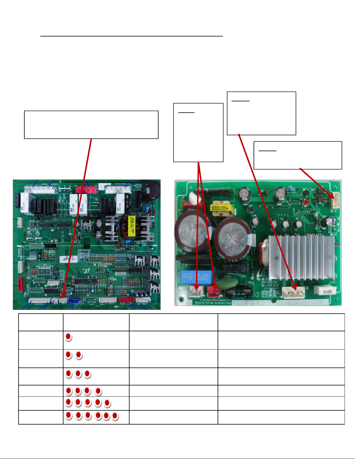
TEST BEFORE INTERPRETING LED BLINKING FREQUENCY
Compressor not running
1. Activate Forced Compressor Operation, wait 2 minutes (in case of high head pressure)
2. If compressor doesn’t start, check CN75 for 2.5vdc (if not there replace Main PCB)
3. If voltage is OK, remove power, disconnect CN03 (Inverter PCB) and check resistance to the
windings. Aproxametly10 ohms. If not correct , inspect wire harness, if OK replace compressor.
4. Disconnect CN02 (SMPS PCB), check resistance to Overload , if open replace overload.
CN03 Compressor
Windings
1 Compressor (Blue)
3 Compressor (Prp)
5 Compressor (Wht)
CN04 Compressor Control
2- (CN76-1) 5vdc (Brn-Gry)
4 Comp Signal (Org)
CN75 To Comp Inverter Board
2- ( CN76-1) (Brn-Gry) 5vdc
4- ( CN76-1) Comp control (Org-Gry) 2.5vdc
CN02
Overload &
A/C Line
1 OLP (Brn)
3 OLP (S/Blu)
3 L (Red)
1 N (Gry)
Protection
Functions
Starting Failure
SPM Fault
Detecting
Position Failure
Motor Locked
Low Voltage
Over Voltage
LED Blinking Frequency Test Replace
Compressor Locking, check input
Compressor Locking, check input
Check the Inverter PCB & Comp
Relay Connectors
If blinking after reset,
Check Inverter Connectors,
Compressor Locking Compressor
voltage
voltage
Connectors OK,replace Inverter PCB, if same,
replace compressor
Check System for restriction & refrigerant, if OK
replace Inverter, if same, replace compressor
Connectors measure OK, replace compressor, if
same, replace Inverter PCB
Replace Inverter PCB, if same, replace
Replace Inverter PCB, if same, replace
Compressor
Compressor
Page 5
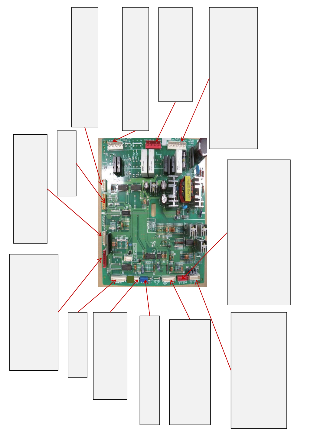
1-2 Damper Heater (Blk-Brn) 12vdc
# tsRF263AE RevA 11/24/2010
5
3-4 Damper Motor (Wht-Blu)
5-6 Damper Motor (Yel-Red)
CN91 Pantry Room Damper
4-7 (Red-Gry) 13vdc
CN78 R LED Light
CN31 Sensor
1-4 Ambient Sensor (Yel-Yel) 1.2~2 vdc
2-(CN90-8) 5vdc to I/M Frz (Blu-S/Blu)
CN74 A/C Load 120vac
5-(CN70-9) Dispenser Valve (W/Blk-Red)
7-(CN70-9) Ice Maker Valve (Prp-Red)
5 Common N (Gry)
9 Heater Common (Org)
CN71 120vac
3-(CN70-1) F Lamp (Prp-Red)
5- (CN71-9) R Defrost/Fill Tube heater (Wht-Org)
7- (CN71-9) F Defrost (Brn-Org)
9- L1 (Red)
11- N (Gry)
8-(CN76-1) R Def Sensor (S/Blu-Gry) 2~4.2vdc
9-(CN76-1) Pantry Sensor (W/Blk-Gry) 2.6~2.8vdc
CN70 120vac
3- 11 French / Disp Heater (Yel-Gry)
3-(CN76-1) F Sensor (Red-Gry) 3.5~4.2vdc
4-(CN76-1) F Def Sensor (Org-Gry) 2.3~4.2vdc
6-(CN76-1) R Sensor (Wht-Gry) 2.4~2.8vdc
1-5 Freezer Dr Sw (Blk-Gry)
2-(CN50-7) R Door Sw (Prp-Gry)
Model: RF266AE**/XAA
CN30 Sensors & Switches
nominal voltages listed
7 Horiz Hall IC Out (Prp)
8 Ground (S/Blu)
5-8 Test Sw (Gry-S/Blu) 5vdc
CN90 Ice Maker
1-2 I/M Mtr (Red-Blk) 12vdc
3-4 Eject Sensor (Wht-Wht) 2.3~3.3vd
CN51 Pantry Room
7-5 (Blu-Wht) 13vdc
control (Org-Gry) 2.5vdc
CN75 Comp Inverter Board
2-(CN76-1) (Brn-Gry) 5 vdc
4-(CN76-1) Compressor
6-1 Fill Tube Htr (Wht-Blu) 13vdc
CN79
5-6 (Yel-Pnk) 5 VDC
7 GND R Door Sw 5vdc
8- (CN76-1) Water Sw (Blu-Pnk)
CN50 Display
4-6 (Org-Pnk) 13 VDC
7 F Fan FG(Brn)
8 R Fan FG(Red)
9 C Fan FG(Blu)
5-1 C Fan (S/Blu-Gry) 7~11vdc
4-1 R Fan (Org-Gry) 7~11vdc
CN76 F, R, C Fans
3-1 F Fan (Yel-Gry) 7~11vdc
Page 6
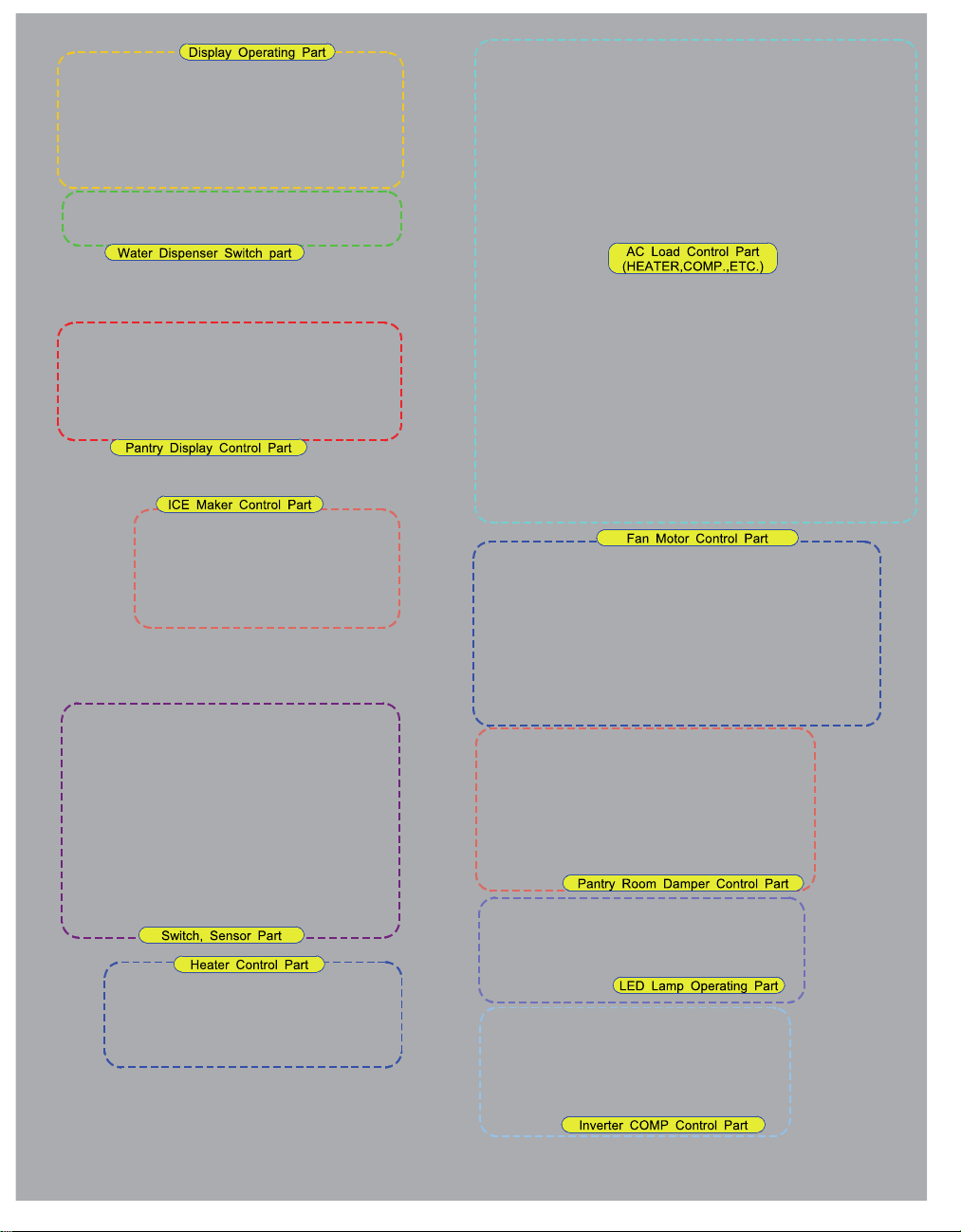
# tsRF263AE RevA 11/24/2010
6
RF263AE
Some Connectors Not Used on this Model
 Loading...