

Fast Track Troubleshooting
Model:
RF28K9070
RF22K9381
RF28K9380
Production; DRRF28K9070
- 060616
IMPORTANT SAFETY NOTICE – “For Technicians Only” This service data
sheet is intended for use by persons having electrical, electronic, and mechanical experience
and knowledge at a level generally considered acceptable in the appliance repair trade. Any
attempt to repair a major appliance may result in personal injury and property damage. The
manufacturer or seller cannot be responsible, nor assume any liability for injury or damage of any
kind arising from the use of this data sheet.
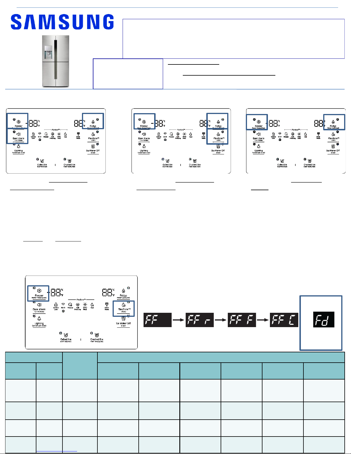
Hold Freezer and Flex zone for 6 seconds until screen
goes blank and you hear a beep . Press Flex zone again
to enter first mode 1
To exit; after mode 5 the screen will be blank, if left
alone for 1min, it will exit to normal operation
DISPLAY
Operating
Time
Operation
Freezer Fridge
F-Fan
(Freezer)
R-Fan
(Fridge)
CV-Fan
(FlexZone)
F Valve R Valve CV Valve
FF 24hr
Continuous
operation
The
temperature
is controlled
Continuous
operation
Swing Swing Swing
FF r 24hr
Continuous
operation
Continuous
operation
Continuous
operation
OFF ON OFF
FF F 24hr
Continuous
operation
Continuous
operation
Continuous
operation
ON OFF OFF
FF C 24hr
Continuous
operation
Continuous
operation
Continuous
operation
OFF OFF ON
mode 1 mode 2 mode 3 mode 4
mode 5
FD = Defrost, all
heaters will
turn on
Demo MODE / Cooling off
Mode
Hold buttons - Freezer, Fridge
and Door Alarm for 6 seconds
until 0 –FF is displayed. Repeat
to exit
Force Mode / Defrost
Load Mode
Diagnostic Mode
Hold buttons - Freezer, Fridge
and Flex Zone for 6 seconds. All
on/off LED’s will blink. Stop
pressing buttons to view load
status.
Refer to PAGE 3 for more detail
Hold buttons – Freezer and
Fridge for 6 seconds, screen will
blink, continue to hold until
blank screen or errors displayed.
After 1 min the mode will exit
Refer to PAGE 4 to 6 for Error
Code details
Support Information:
HELP: 1-888-751-4086 (Tech Sup. – ASC/SSD) - 1-866-894-0637 (Tech Sup. - FE/ME)
GSPN: http://gspn3.samsungcsportal.com/main.jsp
E-Learning: samsungasc.earlyconnect.com
MCP & E-Learning Support: 1-800-749-9421 – e-learning@sea.samsung.com
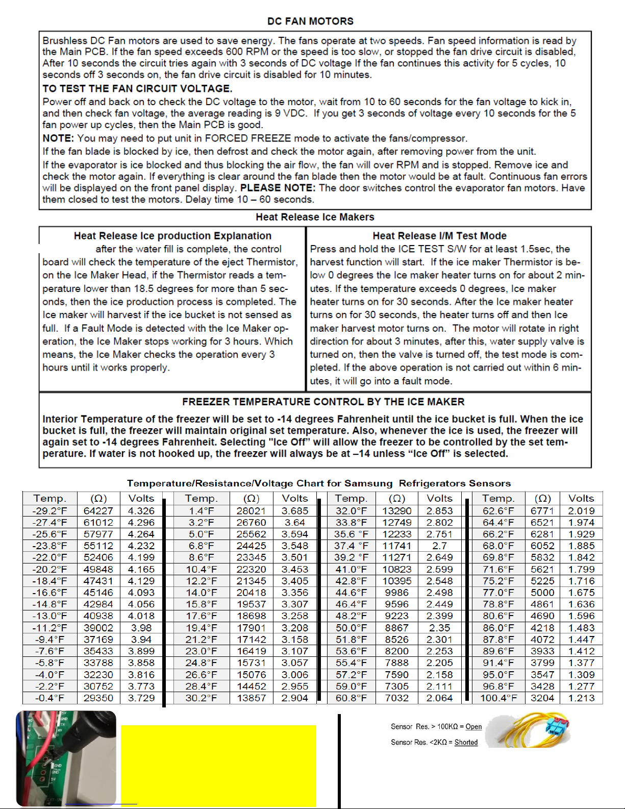
Make sure before measuring voltage of any
DC component that circuit ground is used.
Any marked GND on the main PCB will be
your circuit ground.
If Chassis ground is used, measurements
will be incorrect.
A Sensor Resistance over 100K ohm is considered OPEN
A Sensor Resistance under 2K ohm is considered Shorted
But Note that a sensor could also give wrong values if it is
out of tolerance
Some time
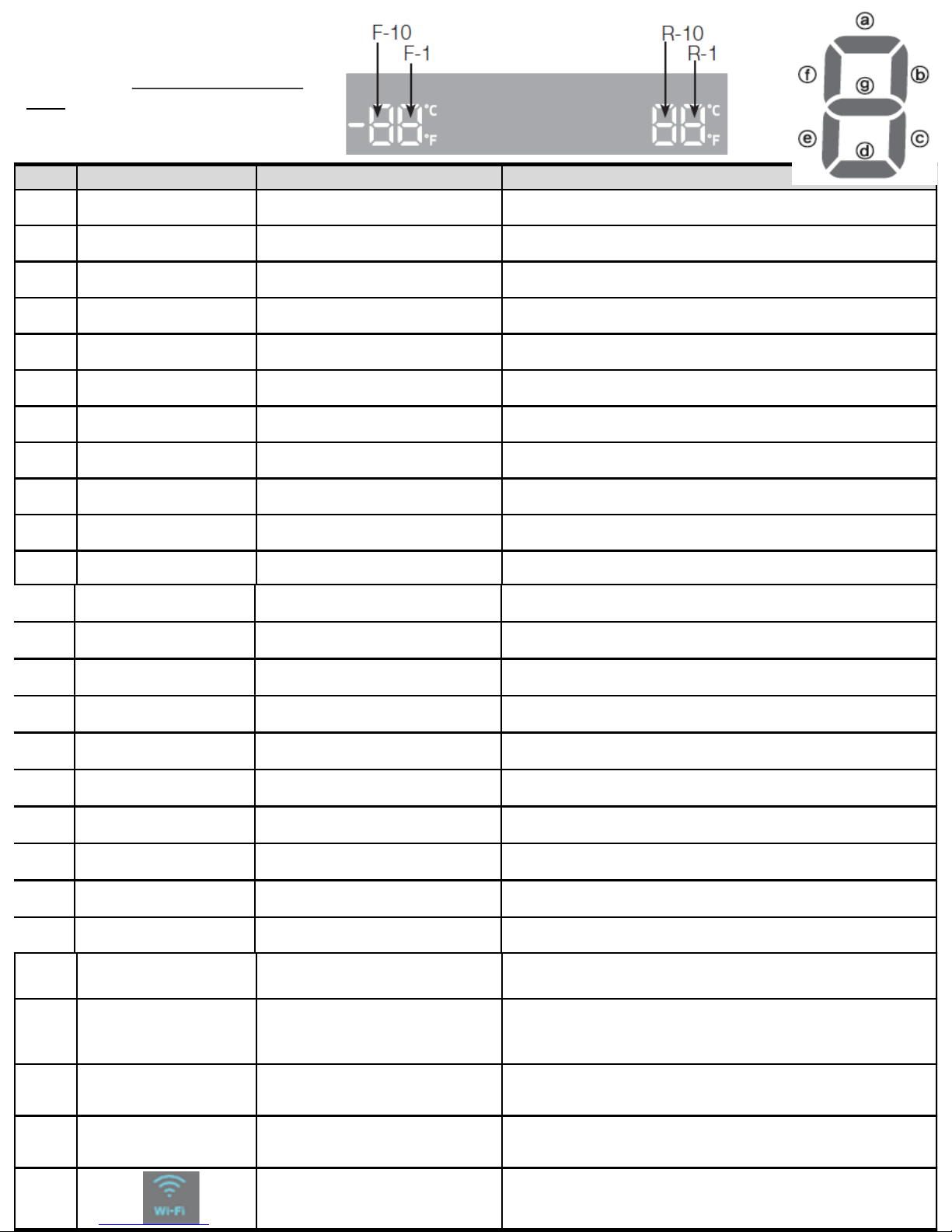
NO Part DISPLAY LED Description
1 R-FAN HIGHEST
"a" and "b" at the lowest order digit of the R
compartment
In the case of the R-FAN HIGHEST operation, the corresponding LED is turned
on.
2 R-FAN HIGH
"a" at the lowest order digit of the R
compartment
In the case of the R-FAN HIGH operation, the corresponding LED is turned on.
3 R-FAN LOW
"b" at the lowest order digit of the R
compartment
In the case of the R-FAN LOW operation, the corresponding LED is turned on.
4 Overload
"e" at the lowest order digit of the R
compartment
If the external air temperature is 34℃ or higher, the corresponding LED is turned
on.
5 Low Temperature
"f" at the lowest order digit of the R
compartment
If the external air temperature is 21℃ or less, the corresponding LED is turned
on.
6 Demo Mode
"g" at the lowest order digit of the R
compartment
The LED is turned on in Demo Mode.
7 COMP
"a" at the lowest order digit of the F
compartment
In the case of the F COMP operation, the corresponding LED is turned on.
8 F-FAN HIGHEST
"b" and "c" at the lowest order digit of the F
compartment
In the case of the F-FAN HIGHEST operation, the corresponding LED is turned
on.
9 F-FAN HIGH
"b" at the lowest order digit of the F
compartment
In the case of the F-FAN HIGH operation, the corresponding LED is turned on.
10 F-FAN LOW
"c" at the lowest order digit of the F
compartment
In the case of the F-FAN LOW operation, the corresponding LED is turned on.
11 F compartment defrost heater
"d" at the lowest order digit of the F
compartment
The LED is turned on when the freezer defrosting heater operates.
12 C-FAN HIGHEST
"e" and "f" at the lowest order digit of the F
compartment
In the case of the C-FAN HIGHEST operation, the corresponding LED is turned
on.
13 C-FAN HIGH
"e" at the lowest order digit of the F
compartment
In the case of the C-FAN HIGH operation, the corresponding LED is turned on.
14 C-FAN LOW
"f" at the lowest order digit of the F
compartment
In the case of the C-FAN LOW operation, the corresponding LED is turned on.
15 F Valve
"b" at the second lowest order digit of the F
compartment
In the case of the F valve open, the LED is turned on.
16 CV Valve
"c" at the second lowest order digit of the F
compartment
If the CV valve opens, the LED is turned on.
17 R Valve
"f" at the second lowest order digit of the F
compartment
If the R valve opens, the LED is turned on.
18 French Heater
"g" at the second lowest order digit of the F
compartment
In the case of the French Heater operation, the corresponding LED is turned on.
19 CV-FAN HIGHEST
“Freezer” or “Thin Ice” for the CV
compartment
In the case of the CV-FAN HIGHEST operation, the corresponding LED is turned
on.
20 CV-FAN HIGH “Freezer” for the CV compartment In the case of the CV-FAN HIGH operation, the corresponding LED is turned on.
21 CV-FAN LOW “Thin Ice” for the CV compartment In the case of the CV-FAN LOW operation, the corresponding LED is turned on.
Hold buttons - Freezer, Fridge and Flex
Zone for 6 seconds. All on/off LED’s will
blink, Stop pressing to view load status.
Refer to next
Load Mode
22
CV compartment defrosting
heater
“Fridge” for the CV compartment
When the CV compartment defrosting heater operates,
the LED is turned on.
23 Normal
"e" and "f" in the lowest order digits of the R
compartment, and the LEDs are all turned off.
When the external temperature is within the range of
22℃~ 33℃.
24 Ice Room-FAN
"d" at the second lowest order digit of the F
compartment
When Ice Room-FAN operates, applicable LED ON.
25 Ice maker full
“e" at the second lowest order digit of the R
compartment
When the Ice Maker's Bucket is full, applicable LED ON
26 WiFi Status
Not connected to the IP sharer (AP) or the Internet: Off
Router(AP) connected: Blink
Internet connected: On
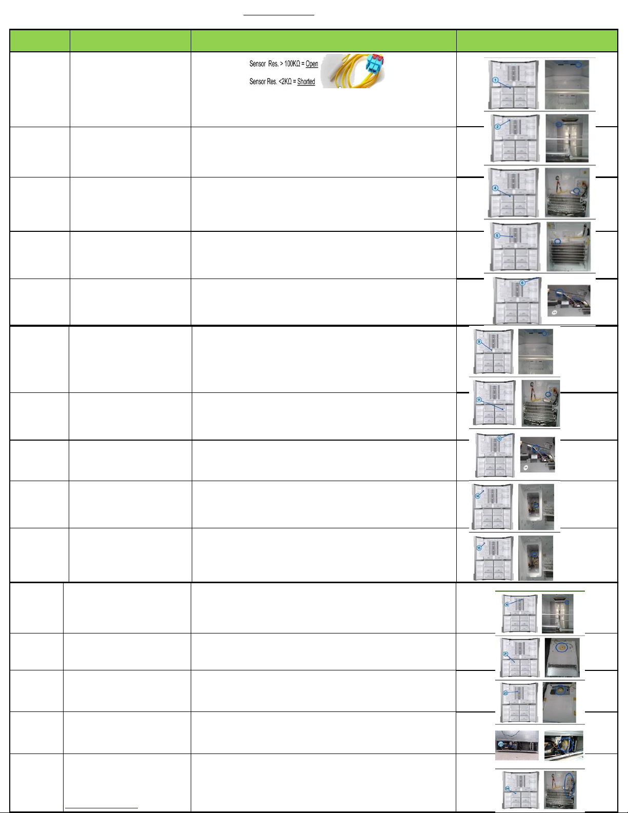
ERROR
NUMBER
Item Diagnostic method Location Image
1
Freezer sensor
error
Check if the Sensor is Open or Shorted
The voltage between the Main PCB CN30 pins 1
and 3 should be within the 4.5V~1.0V range.
2
Fridge sensor
error
Check if the sensor is open or shorted
The voltage between the Main PCB CN30 pins 1
and 5 should be within the 4.5V~1.0V range.
4
Freezer defrost
sensor error
Check if the sensor is open or shorted
The voltage between the Main PCB CN30 pins 1
and 4 should be within the 4.5V~1.0V range.
5
Fridge defrost
sensor error
Check if the sensor is open or shorted
The voltage between the Main PCB CN30 pins 1
and 6 should be within the 4.5V~1.0V range.
6
Ambient sensor
error
Check if the sensor is open or shorted
The voltage between the Main PCB CN30 pins 1
and 2 should be within the 4.5V~1.0V range.
9
Convertible zone
sensor error
Check if the sensor is open or shorted
The voltage between the Main PCB CN30 pins 11
and 12 should be within the 4.1V~0.8V range.
11
Convertible zone
defrost sensor error
Check if the sensor is open or shorted
The voltage between the Main PCB CN30 pins 11 and 13
should be within the 4.1V~0.8V range.
13
Humidity sensor
error
The voltage between the Main PCB CN30 pins 7
and 9 should be within the 4.1V~0.8V range.
14
Fridge Ice maker
sensor error
Check if the sensor is open or shorted
The voltage between MAIN PCB CN90 3↔
8 should be within 4.5V~1.0V.
15
Ice room sensor
error
Check if the sensor is open or shorted
The voltage between MAIN PCB CN30 10↔
11should be within 4.5V~1.0V.
16
Fridge humidity
sensor error
Check if the sensor is open or shorted
The voltage between the Main PCB CN30 pins 7
and 8 should be within the 4.1V~0.8V range.
21 Freezer fan error
The voltage of the MAIN PCB CN74 1↔4: should
be between 7V~12V.
22 Fridge fan error
The voltage of the MAIN PCB CN74 1↔3: should
be between 7V~12V.
23
Comp room fan
error
The voltage of the MAIN PCB CN74 1↔6: should
be between 7V~12V.
24
Freezer defrost
error
After separating MAIN PCB CN70_1 wire from PCB,
resistance value between CN70_1-7 ↔ 3 shall be 63(230)
ohm ± 7%. (Resistance value is varied by
input power) 0 ohm : heater short, ∞ ohm : wire/
bimetal open (Must power off)
Hold buttons – Freezer and Fridge for 6 seconds, screen will blink, continue to hold until blank screen or errors
displayed. After 1 min the mode will exit
Diagnostic mode

ERROR
NUMBER
Item Diagnostic method Location Image
29
Convertible zone
defrost error
After separating MAIN PCB CN70 wire from PCB,
resistance value between CN70_1-7 ↔ 1 shall be
63(230) ohm ± 7%. (Resistance value is varied by
input power) 0 ohm : heater short, ∞ ohm : wire/
bimetal open (Must power off)
31
Convertible zone
fan error
The voltage of the MAIN PCB CN74 1↔5: should
be between 7V~12V.
35 Freezer low regist ERROR_Freezer low regist
37
Convertible zone
low regist
ERROR_Convertible zone low regist
39
Ice maker function
error
After changing the Ice Maker(R), plug the
refrigerator power code again, and check the
operation.
40 Ice maker fan error
The voltage of MAIN PCB CN52
-
1↔ 6: shall be between
7V~12V
41
MAIN < - > Panel
Comm error
Actually, If there is not a problem, it is desirable to
replace Main and Panel PCB With the oscilloscope after
a cable problem confirming.
44
MAIN < - > INV
Comm error
Actually, If there is not a problem, it is desirable to
replace Main and Inverter PCB With the
oscilloscope after a cable problem confirming.
46
I/O Expander
Comm error
It is desirable to replace Main PCB.
61
Ice duct heater
error
After separating MAIN PCB CN51 wire from PCB,
resistance
value between CN51 4↔6 shall be 135 ohm
±
7%. (Resistance value is varied by input
power) 0 ohm : heater short, ∞ ohm :
(Must power off)
65
Ice bucket heater
error
After separating MAIN PCB CN51 wire from PCB,
resistance
value between CN51 4↔7 wire shall be 135 ohm
±
7%. 0 ohm : heater short, ∞ Ohm : wire.
66
Door handle
heater error
After separating MAIN PCB CN51 wire from PCB,
resistance
value between CN51 1↔2 wire shall be 135 ohm
±
7%. 0 ohm : heater short, ∞ Ohm : wire.
71
Freezer abnormal
temp. error
The temperature has been abnormally increased. Check if
the door has been open for a long time or if hot food has
been stored in the compartment. If the reason for the error is
removed, the error code disappears after a pre-
determined
period of time.
72
Fridge abnormal
temp. error
Check if the door has been open for a long time or if hot
food has been stored in the compartment. If the reason for
the error is removed, the error code disappears after a pre-
determined period of time.
73
Convertible zone
chill error
Check if the door has been open for a long time or if hot
food has been stored in the compartment. If the reason for
the error is removed, the error code disappears after a pre-
determined period of time.

ERROR
NUMBER
Item Diagnostic method
Location Image
81 COMP run error
Check the soldering status of the inverter PCB.
(
Check if any parts have short-
circuited). Check if the DC 15V output
is less than 13.5V. Check the
Comp and Cycle.
82 COMP IPM fault
Check the soldering status of the inverter PCB.
(
Check if any parts have short-
circuited). Check if the DC 15V output
is less than 13.5V. Check the
Comp and Cycle.
83
COMP current
error
Check the compressor wire connections. Check
the soldering status of the inverter PCB. (Check if any parts have
short-circuited). Check the Comp
and Cycle.
84 COMP Motor stall
Check if the compressor and the Cycle is normal.Check the input
voltage. Check the soldering of
the inverter PCB. (Check if any parts have short-
circuited.)
85 COMP low voltage
Check the input voltage. (This error occurs when the input voltage is
AC 106 V or lower.)
Communication error between Display and Main PCB – check
connections

Symptom Action
The front corners and sides become warm and form
condensation.
• To prevent condensation from forming, the refrigerator has heat-proof piping in the front corners. If
the ambient temperature rises, this equipment may not work effectively. This is not a system failure.
• Make sure the door is closed properly. Condensation may form if you leave the door open for an
extended period of time.
• Condensation may form on the exterior surface of the refrigerator if humid air comes into contact with
the cool surface of the refrigerator.
The ice maker does not make ice.
• If you have used all the ice in the ice bucket, you must wait for 12 hours for the refrigerator to make
more ice.
• See if the Ice Maker Off icon is lit. On the family hub under Fridge Manager, if off turn on
• Make sure the freezer temp is set properly.
• Make sure the water tank is filled with water.
• Check if the ice bucket contains ice clumps. If it does, empty the ice bucket and try again.
The water dispenser is not functioning.
• Check if the water tank is frozen. If so, select a higher fridge temperature.
• Make sure the water tank is filled with water.
• Make sure the water tank is installed properly.
• Make sure the water filter is installed properly.
You hear a bubbling sound. • This is normal. The bubbling sound comes from refrigerant circulating through the refrigerator.
A bad smell comes from inside the refrigerator.
• Check for any spoiled food. We recommend cleaning the refrigerator on a regular basis and removing
any spoiled or suspect food items.
• Make sure strong smelling food is wrapped tightly or stored in air tight containers.
Frost forms on the interior walls.
• Make sure no food blocks the vents of the refrigerator. It is also important to arrange food items
evenly for ventilation.
• Make sure the door is closed properly.
Condensation forms on the interior walls or around
vegetables.
• This happens when food containing a high proportion of water is stored uncovered, or the door has
been left open for an extended period of time.
• Make sure food is covered or put in sealed containers.
General

Symptom Action
Could not find “Samsung Smart Home” in the app market.
• The Samsung Smart Home app is available for smartphones that run Android 4.0 (ICS) or higher, or
iOS 7.0 or higher
The Samsung Smart Home app fails to operate.
• The Samsung Smart Home app is available on applicable models only.
• The old Samsung Smart Refrigerator app cannot connect with Samsung Smart Home models.
The Samsung Smart Home app is installed but is not
connected to my refrigerator.
• You must log into your Samsung account to use the app. • Make sure that your router is operating
normally.
• If the Wi-Fi icon on the refrigerator’s display is off, this indicates that no network connection has
been established yet. In this case, use the Samsung Smart Home app to connect and register your
refrigerator to the access point (AP) of your house.
Could not log into the app.
• You must log into your Samsung account to use the app.
• If you don’t have a Samsung account, follow the app’s onscreen instructions to create one.
An error message appears when I try to register my
refrigerator.
• Easy Connection may fail due to the distance from your access point (AP) or electrical interference
from the surrounding environment. Wait a moment and try again.
The Samsung Smart Home app is successfully connected to
my refrigerator but does not run.
• Exit and restart the Samsung Smart Home app, or disconnect and reconnect the router.
• Unplug the power cord of the refrigerator, and plug it again after 1 minute.
Samsung Smart Home - Troubleshooting

Removal of Ice Bucket and Ice Maker Removal of the Auger Motor Assy

TDM VALVE
#1 Input from Drier
#3 Outputs to Evaporators
FF Section – Yellow Tube
FRE Section – No Color
Conv. Zone – Red Tube

Main Board of Fridge Layout
SMPS
Inverter Board (Compressor)
[Caution]
AC input power and high voltage
generated at SMPS PCB and INVERTER
PCB power terminal. Please be cautious
during repair and measurement.

Wiring Diagram
Dispenser
 Loading...