

Samsung RD-840/1640 User Manual

8 CHANNEL/
16 CHANNEL
DVR
User Manual
SRD-840/1640

Copyright
©
2012 Samsung Techwin Co., Ltd. All rights reserved.
Tra de mar k
is the registered logo of Samsung Techwin Co., Ltd.
The name of this product is the registered trademark of Samsung Techwin Co., Ltd.
Other trademarks mentioned in this manual are the registered trademark of their respective company.
Restriction
Samsung Techwin Co., Ltd shall reserve the copyright of this document. Under no circumstances, this document shall be reproduced, distributed or
changed, partially or wholly, without formal authorization of Samsung Techwin.
Disclaimer
Samsung Techwin makes the best to verify the integrit y and correctness of the contents in this document, but no formal guarantee shall be provided.
Use of this document and the subsequent results shall be entirely on the user's own responsibility. Samsung Techwin reserves the right to change the
contents of this document without prior notice.
Design and specifications are subject to change without prior notice.
The default password can be exposed to a hacking thread so it is recommended to change the password after installing the product.
Note that the securit y and other related issues caused by the unchanged password shall be responsible for the user.
8 Channel/
16 Channel DVR
User Manual

English _3
OVERVIEW
IMPORTANT SAFETY INSTRUCTIONS
Read these operating instructions carefully before using the unit.
Follow all the safety instructions listed below.
Keep these operating instructions handy for future reference.
1) Read these instructions.
2) Keep these instructions.
3) Heed all warnings.
4) Follow all instructions.
5) Do not use this apparatus near water.
6) Clean only with dry cloth.
7) Do not block any ventilation openings, Install in accordance with the manufacturer’s instructions.
8) Do not install near any heat sources such as radiators, heat registers, stoves, or other
apparatus (including amplifiers) that produce heat.
9) Do not defeat the safety purpose of the polarized or grounding- type plug. A polarized plug has
two blades with one wider than the other. A grounding type plug has two blades and a third
grounding prong. The wide blade or the third prong are provided for your safety. if the provided
plug does not fit into your outlet, consult an electrician for replacement of the obsolete outlet.
10) Protect the power cord from being walked on or pinched particularly at plugs, convenience
receptacles, and the point where they exit from the apparatus.
11) Only use attachments/accessories specified by the manufacturer.
12) Use only with the cart, stand, tripod, bracket, or table specified by the
manufacturer, or sold with the apparatus. When a cart is used, use
caution when moving the cart/apparatus combination to avoid injury from
tip-over.
13) Unplug this apparatus during lightning storms or when unused for long
periods of time.
14) Refer all servicing to qualified service personnel. Servicing is required when the apparatus has
been damaged in any way, such as power-supply cord or plug is damaged, liquid has been
spilled or objects have fallen into the apparatus, the apparatus has been exposed to rain or
moisture, does not operate normally, or has been dropped.
overview

4_ overview
overview
BEFORE START
This user manual provides Information for using the DVR such as brief introduction, part names, functions, connection
to other equipment, menu setup, etc.
You have to keep in mind the following notices :
• SAMSUNG retains the copyright on this manual.
• This manual cannot be copied without SAMSUNG’s prior written approval.
• We are not liable for any or all losses to the product incurred by your use of non-standard product or violation of
instructions mentioned in this manual.
• Prior to opening the case, please consult a qualified technician first. Whenever this is needed power must be
removed from the unit.
• Before installing an additional HDD or connecting an external storage device (USB memory or USB HDD) to this
DVR, check the compatibility. Consult your provider for the compatibility list.
Warning
❖ Battery
It is essential that when changing the battery in the unit, the replacement battery must be of the same type
otherwise there may be a possibility of an explosion.
The following are the specifications of the battery you are using now.
• Normal voltage : 3V
• Normal capacity : 170mAh
• Continuous standard load : 0.2mA
• Operating temperature : -20°C ~ +85°C
(-4°F ~ +185°F)
Caution
• Connect the power cord into a grounded outlet.
• The Mains plug is used as a disconnect device and shall stay readily operable at any time.
• Batteries shall not be exposed to excessive heat such as sunshine, fire or the like.
• Risk of Explosion if Battery is replaced by an Incorrect Type. Dispose of Used Batteries According to the
Instructions.
❖ System Shutdown
Turning off the power while the product is in operation, or undertaking improper actions may cause damage
or malfunction to the hard drive or the product.
Disconnecting the power cable for power off.
For a safe power disconnection, select <OK> in the system shutdown dialog before unplugging the power cord.
You may want to install a UPS system for safe operation in order to prevent damage caused by an
unexpected power stoppage. (Any questions concerning UPS, consult your UPS retailer.)
❖ Operating Temperature
The guaranteed operating temperature range of this product is 0°C ~ 40°C (32°F ~ 104°F).
This product may not work properly if you run right after a long period of storage at a temperature below the
guaranteed one.
Prior to using a device that has been stored for a long period in low temperatures, allow the product to stand
at room temperature for a period.
Especially for the built-in HDD in the product, its guaranteed temperature range is 5°C ~ 55°C (41°F ~ 131°F).
Likewise, the hard drive may not work at a temperature below the guaranteed one.
CALIFORNIA USA ONLY
This Perchlorate warning applies only to primary CR (Manganese Dioxide)
Lithium coin cells in the product sold or distributed ONLY in California USA.
“Perchlorate Material - special handling may apply,
See www.dtsc.ca.gov/hazardouswaste/perchlorate.”

English _5
OVERVIEW
CONTENTS
OVERVIEW
3
3 Important Safety Instructions
4 Before Start
5 Contents
7 Features
9 Part Names and Functions (Front)
10 Part Names and Functions (Rear)
11 Remote Control
CONNECTING WITH OTHER DEVICE
12
12 Installation
12 Checking the installation environment
13 Connecting the Video, Audio, and Monitor
13 Connecting the USB
13 Connecting POS Device
14 Connecting the Alarm Input/Output
14 Connecting the RS-485 Device
15 Connecting the Network
LIVE
17
17 Getting Started
19 Live Screen Configuration
23 Live Mode
25 Spot Out
26 Zoom
26 Audio ON/OFF
26 Freeze
27 Event Monitoring
USING THE DVR
28
28 System Setup
38 Setting the Device
46 Setting the Recording
49 Setting the Event
52 Backup
53 Network Configuration
61 Controlling a PTZ device

6_ overview
overview
SEARCH & PLAY
64
64 Search
67 Playback
WEB VIEWER
69
69 Introducing Web Viewer
70 Connecting Web Viewer
71 Using Live Viewer
77 Using Search Viewer
81 Viewer Setup
92 About
93 Mobile Viewer
BACKUP VIEWER
94
94 SEC Backup Viewer
APPENDIX
96
96 Product Specification
99 Product Overview
101 Default Setting
104 Troubleshooting
107 Open Source License Report on the Product

English _7
OVERVIEW
FEATURES
This DVR enables you to compress 8 or 16 channels of camera video sources into H.264 format, and to compress
4 channels of sound sources simultaneously before saving and recording on the HDD.
These DVRs also supports network connectivity, providing remote monitoring from a remote PC transferring video
and audio data.
• Provides a convenient User Interface
• 8/16 CH Composite Input Connectors
• Supports CIF(S)/2CIF(M)/4CIF(L) recording formats
• With the network specific codec, network transfer enabled regardless of the recording conditions
• Display of HDD information and status by using HDD SMART
• Hard Disk overwrite function
• Mass storage hard disk backup through high-speed USB 2.0
• Simultaneous Record and Playback of 8/16-channel video data
• Various Search Modes (Time, Event, Backup, Pos, Motion Detection)
• Various Recording Modes (Manual, Event, Scheduled Recording)
• Alarm Interface
• Remote Monitoring function by Network Viewer, Smart Viewer and Mobile Viewer
8_ overview
overview
Standards Approvals
M
This equipment has been tested and found to comply with the limits for a Class A digital device, pursuant to part 15
of the FCC Rules. These limits are designed to provide reasonable protection against harmful interference when the
equipment is operated in a commercial environment.
This equipment generates, uses, and can radiate radio frequency energy and, if not installed and used in accordance
with the instruction manual, may cause harmful interference to radio communications. Operation of this equipment
in a residential area is likely to cause harmful interference in which case the user will be required to correct the
interference at his own expense.
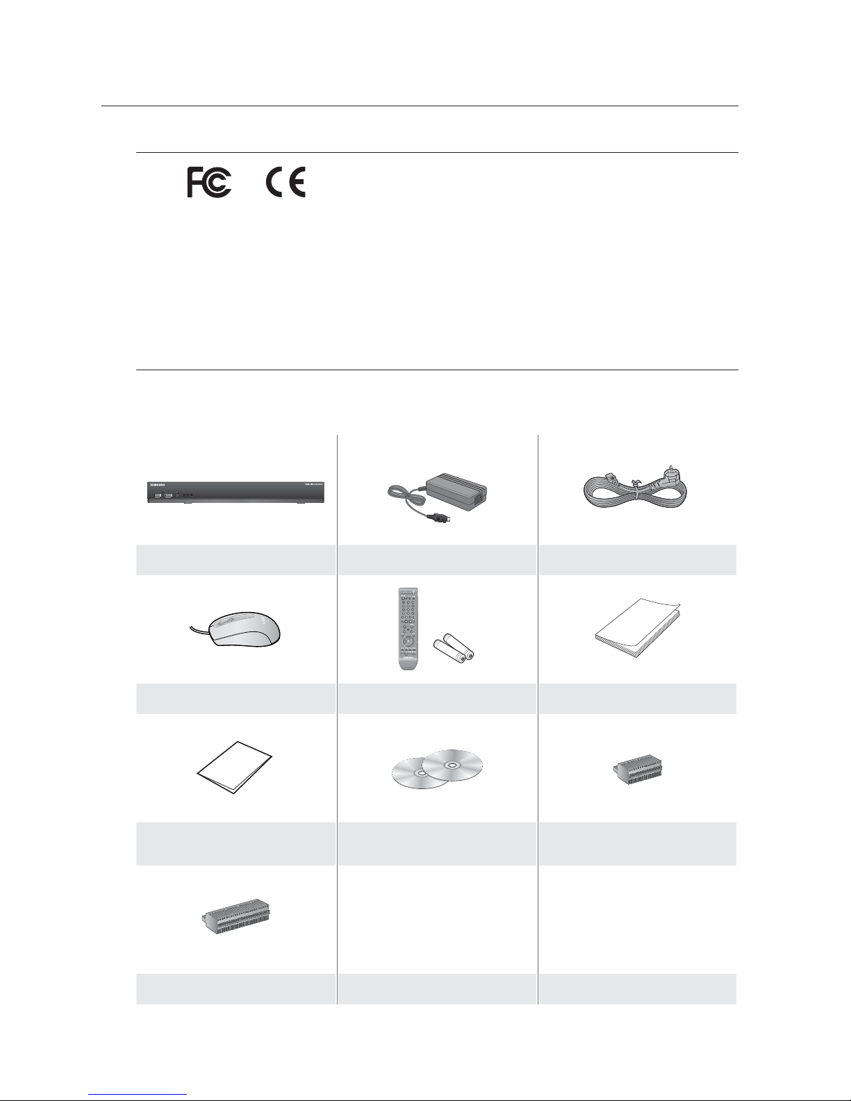
Package Contents
Please unwrap the product, and place the product on a flat place or in the place to be installed.
Check if the main unit and all the following accessories are included in the product package.
DVR Adapter Power Cable
Mouse Remote Control / Battery (AAA x 2) User Manual
Quick Guide (optional)
Network Viewer Software /
User Manual CD
Terminal Block (SRD-840)
Terminal Block (SRD-1640)
English _9
OVERVIEW
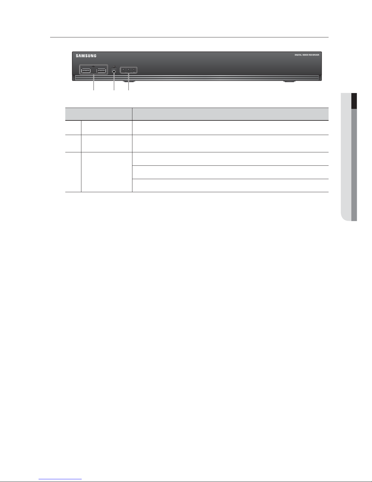
PART NAMES AND FUNCTIONS (FRONT)
Part Names Functions
USB Port Connects the USB devices.
b
Remote Control
Receiver
Input the remote control signal.
c
LED Indicator
POWER : Displays the power ON/OFF status.
ALARM : Lights on when an event occurs.
REC : Lights on when recording is in progress.
cb
10_ overview
overview
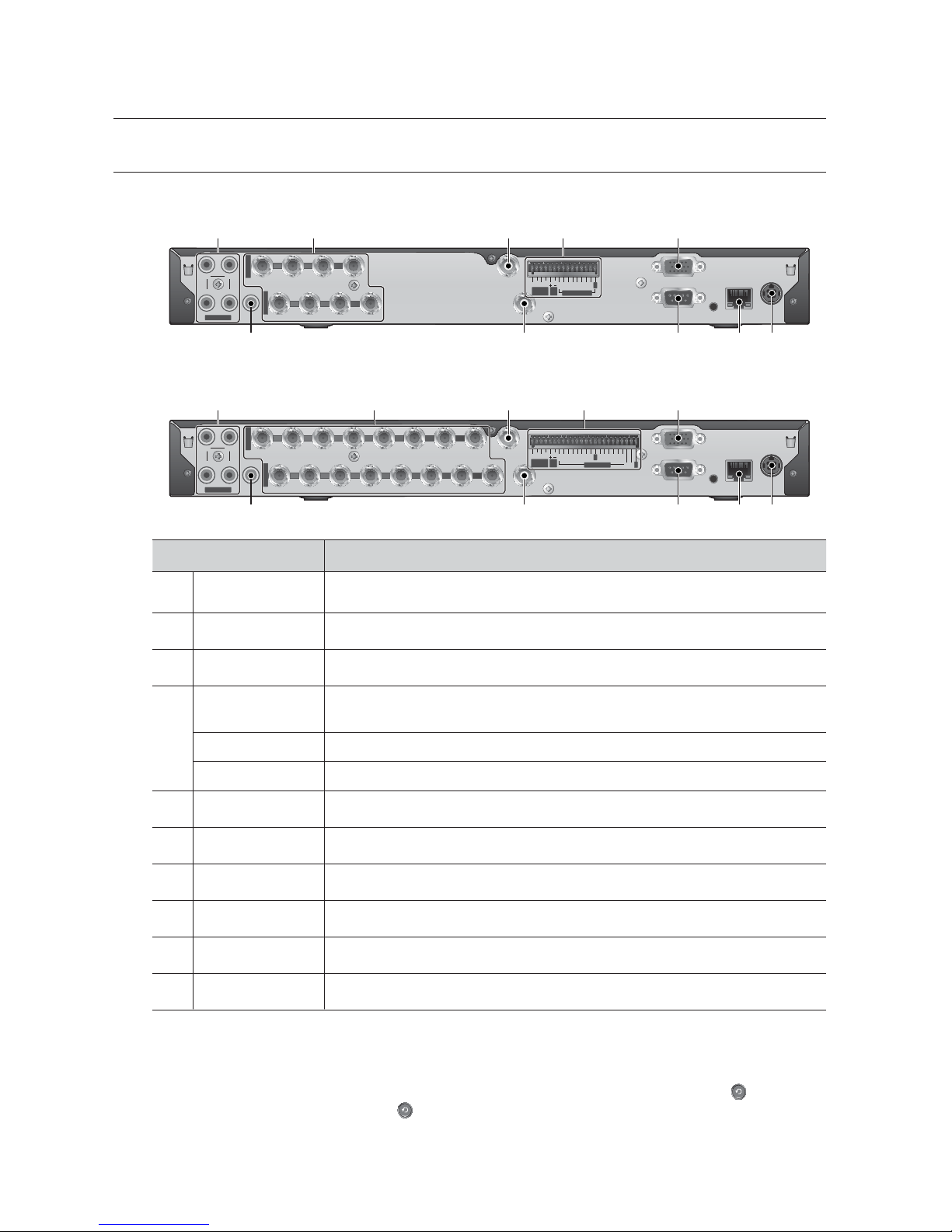
PART NAMES AND FUNCTIONS (REAR)
SRD-840
SRD-1640
Part Names Functions
AUDIO IN Input ports (RCA jack) for the audio signal.
b
VIDEO IN Input port for the composite video signal.
c
SPOT BNC type of output port for the Spot signal.
ALARM IN
1~8, G : Alarm Input port.
1~16, G : Alarm Input port.
ALARM OUT 1~2, COM : Alarm Output port.
RS-485 Used to establish RS-485 communications.
VGA OUT Output port for VGA video signal.
DC 12V DVR power input port.
NETWORK NETWORK connector port.
SERIAL Serial port for connecting to a POS device.
VIDEO OUT BNC type of output port for the composite video signal.
AUDIO OUT Output port (RCA jack) for the audio signal.
M
[CONSOLE] is designed for the service repair purpose only.
If you want to change the default output to VGA mode when the live screen is displayed with the beep after the
system booting, press the remote control buttons in sequence: [FREEZE] [VIEW] [RETURN (
)]
[FREEZE] [VIEW] [RETURN ( )]. The DVR will switch to VGA mode with the beep after rebooting.
For more information about monitor output, refer to “Video Output”. (Page 44)
NETWORK
CONSOLE
VGA OUT
SERIAL
VIDEO OUT
87654321
CH1 CH2
CH3 CH4
9 10111213141516
SPOT
AUDIO OUT
DC 12 V
AUDIO IN
VIDEO IN
VIDEO IN
NETWORK
CONSOLE
VGA OUT
SERIAL
VIDEO OUT
4321
CH1 CH2
CH3 CH4
5678
SPOT
AUDIO OUT
DC 12 V
AUDIO IN
VIDEO IN
VIDEO IN
1
ALARM
OUT
RS485
COM COM
2
1
234 5 6 7 8 G1 23456 7 8 G
ALARM IN
b c
NETWORK
CONSOLE
VGA OUT
SERIAL
VIDEO OUT
8764321
CH1 CH2
CH3 CH4
9 10111213141516
SPOT
AUDIO OUT
DC 12 V
AUDIO IN
VIDEO IN
VIDEO IN
NETWORK
CONSOLE
VGA OUT
SERIAL
VIDEO OUT
87654321
CH1 CH2
CH3 CH4
9 10111213141516
SPOT
AUDIO OUT
DC 12 V
AUDIO IN
VIDEO IN
VIDEO IN
1
ALARM
OUT
RS485
COM COM
212 3 4 5 6 7 891011 12
1314
1516
G
G
ALARM IN
b c

English _11
OVERVIEW
REMOTE CONTROL
Using the Numeric buttons
CHANNEL 1–9 Press each button between 1 to 9.
CHANNEL 10 Press the [+10] button first, then press the 0 button again within 3 seconds.
CHANNEL 11–16 Press the [+10] button first, then press any number between 1 to 6 within 3 seconds.
Changing the Remote Control ID
1. Press the ID button of the remote control and check the ID displayed on the DVR screen.
The factory default ID of the remote control is 00.
2. Enter 2 digits of your selection in order, while pressing the system [ID] button.
3. When ID input is done, press the system [ID] button again to check the setting.
M
If you want to change the remote control ID to 08: Press 0 and 8 in order while the system [ID] button is pressed.
Remote control's ID and DVR’s ID should be matched for proper operation. Refer to “Remote Devices”. (Page 42)
SEARCH
Displays the search menu.
POWER
Displays the Exit pop up screen.
NUMBER [0~+10]
Used as the numeric input keys, or displays a single
channel.
T/W
Zooms in or out.
BACKUP
Displays the Backup Menu.
MODE
Changes the screen mode.
MENU
Goes to the system menu screen.
Up/Down/Left/Right(▲▼◄ ►)/ENTER
Moves the cursor up/down/left/right, and runs the
Select Menu.
FREEZE
Freezes the screen temporarily.
ZOOM
Runs the digital zoom (x2) function.
VIEW
Runs the View function in the PTZ mode.
DVR
Activates the DVR function.
ID
Sets the ID of the system.
Select 2 digits from 0 ~ 9 while pressing the ID Key.
PTZ
Displays or ends PTZ.
SCROLL ,.
Moves the menu scroll.
RETURN
Returns to the previous screen.
AUDIO
Turns Audio on/off.
ALARM
Cancels the Alarm.
REC LOCK
Selects the recording lock function.
PRESET
Displays the Preset Setup.
REC
Starts or ends the live recording.
Skip Backward (by unit time),
Step Backward, Step Forward,
Skip Forward (by unit time)
Move Frame
While paused, moves to the previous/next frame.
FR, STOP, PLAY/PAUSE, FF
12_ connecting with other device
connecting with other device
INSTALLATION
Please take note of the followings before using this product.
• Do not use the product outdoor.
• Do not spill water or liquid in the connection part of the product.
• Do not impose the system to excessive shock or force.
• Do not pull out the power plug forcefully.
• Do not disassemble the product on your own.
• Do not exceed the rated input/output range.
• Use a certified power cord only.
• For the product with an input ground, use a grounded power plug.
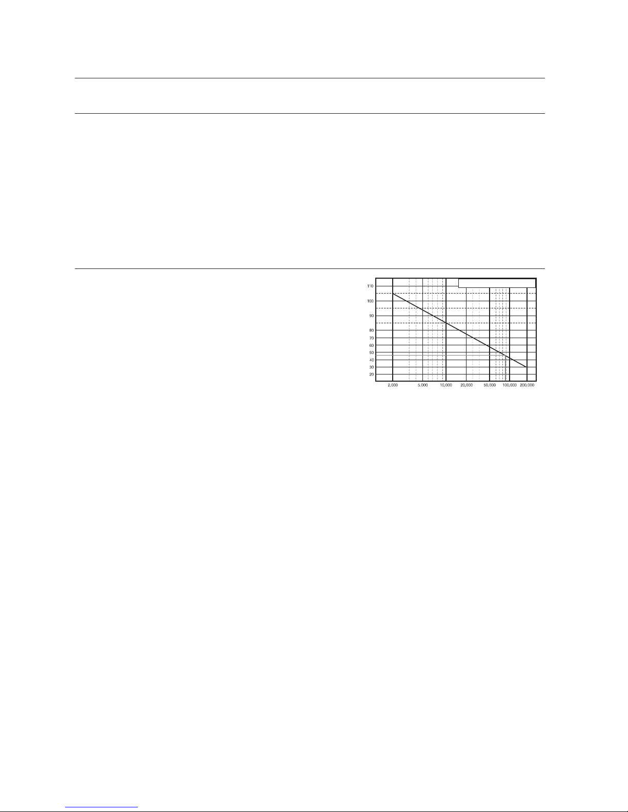
CHECKING THE INSTALLATION ENVIRONMENT
Samsung Digital Video Recorder (“DVR” hereinafter) is a
state-of-art security device, and contains mass storage hard
disk(s) and critical circuits inside.
When the temperature rises inside the product, the product
may breakdown and the product life be shortened.
One Year: 24HR X 365 DAY =8,760 HR
Temperature
Unit: ºC
Life (Unit: HOURS)
English _13
CONNECTING WITH OTHER DEVICE
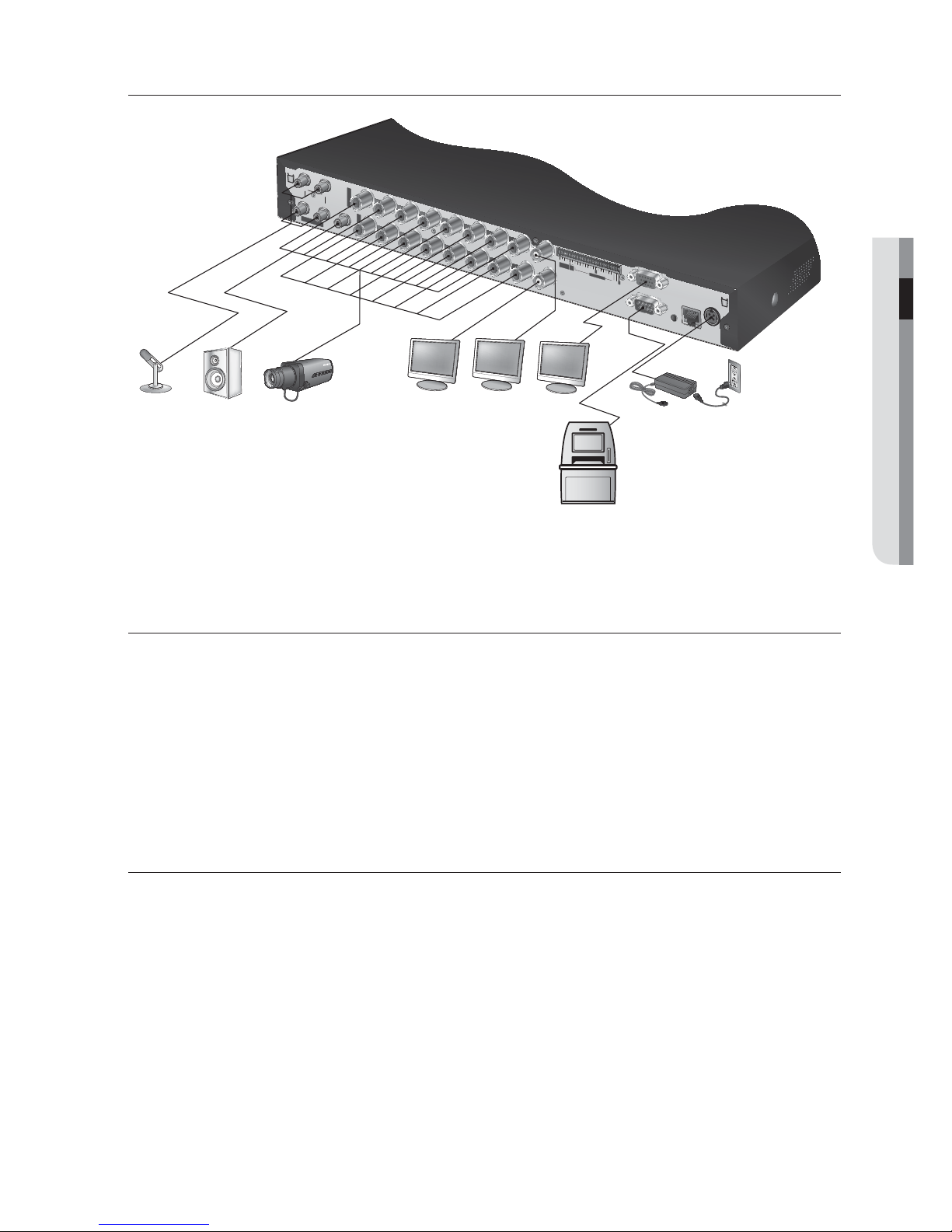
CONNECTING THE VIDEO, AUDIO, AND MONITOR
M
The following figures are based on Model SRD-1640.
CONNECTING THE USB
1. By factory default, a USB port is provided for external connection.
2. You can connect a USB HDD, USB memory or mouse to the USB port.
3.
If a USB HDD is connected to the system, recognition and settings are available in “Menu > Setting the Device >
Storage Device”. (Page 40)
4. This product supports hot-plugging, which connects/removes the USB device during the system operation.
J
If you use the USB device for Backup purposes, format it with FAT32 on PC if it is not formatted on the DVR.
CONNECTING POS DEVICE
1. You can connect a POS device to the RS-232C port on the product’s rear side when you connect it directly with
a RS-232C cable.
2. Connection setup for the RS-232C port is available in “Menu > Device > POS Devices”, press the
<POS Device Setup> button and set <Baudrate, Parity, Data, Stop bit and Transfer Type>. (Page 42)
CONSOLE
AUDIO IN
CH1
CH2
VGA OUT
SERIAL
DC 12V
NETWORK
AUDIO IN
VIDEO IN
VIDEO IN
1
2
3
4
5
6
7
8
SPOT
9
10
11
12
13
14
15
16
VIDEO OUT
CH3
CH4
AUDIO OUT
12
13
1
ALARM
OUT
RS485
COM
COM
2
1
2
3
4
5
6
7
8
9
10
11
14
15
16
G
G
ALARM IN
14_ connecting with other device
connecting with other device
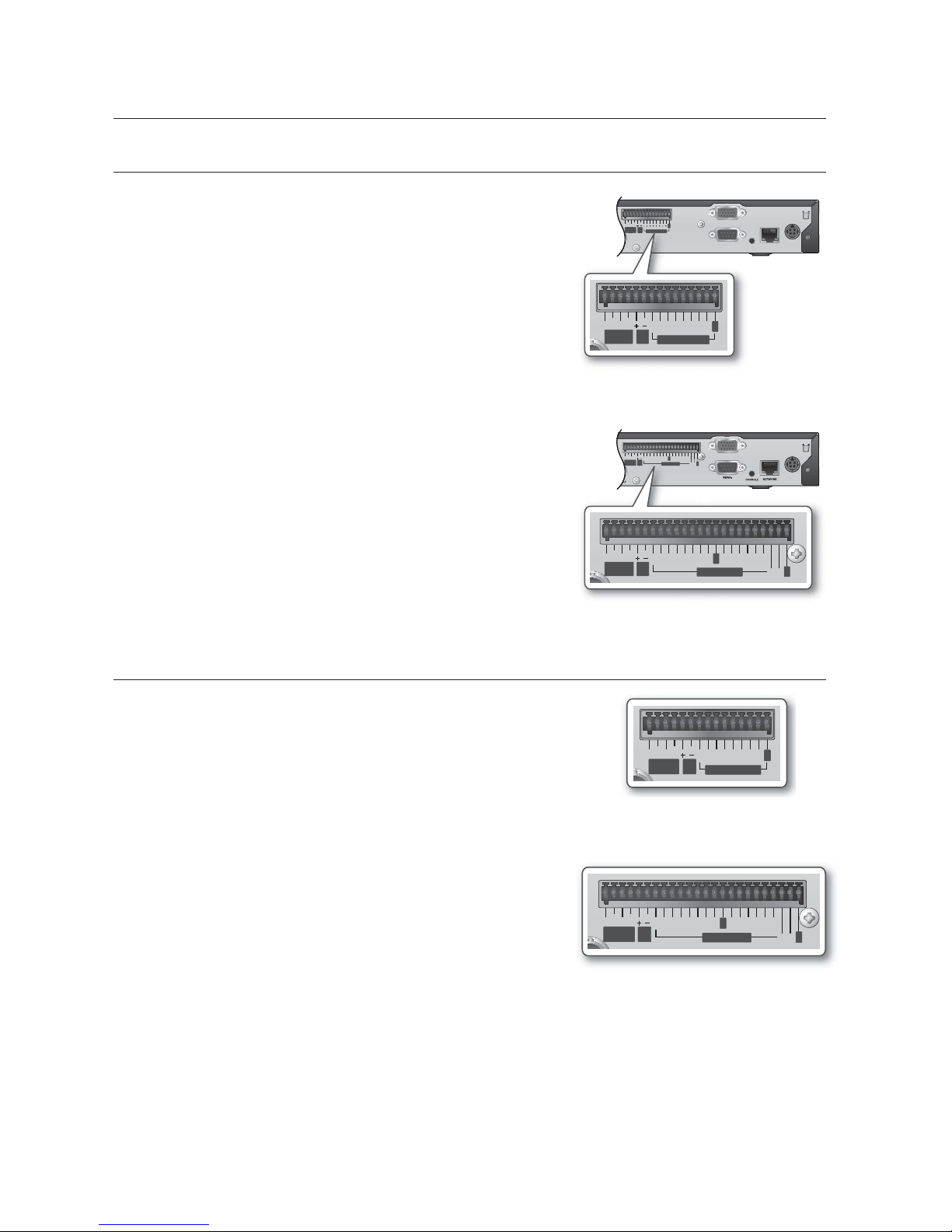
CONNECTING THE ALARM INPUT/OUTPUT
Connecting the alarm input signal
Connect one strand of the sensor signal line to one of 8/16 strands
of the alarm input port, and connect the other strand to the [G] port.
Connecting the alarm output signal
Connect one strand of the sensor signal line to the alarm output
port and connect the other to the [COM] port.
• ALARM IN : 5mA sink
• ALARM OUT : 24V DC 1A, 125VAC/0.5A
CONNECTING THE RS-485 DEVICE
Connect the rear [RS-485 +, –] port to the PTZ camera or system
keyboard.
M
You can connect and control the PTZ camera which supports the
RS-485 communication.
Check if the RS-485 device is compatible with the product first.
Pay attention not to change the polarity (+/-) of the RS-485 device
when connecting it.
Depending on camera’s type, connection polarity can be different.
For further information, refer to the respective PTZ Camera’s
documentation.
NETWORK
CONSOLE
VGA OUT
SERIAL
VIDEO OUT
DC 12 V
NETWORK
CONSOLE
VGA OUT
SERIAL
VIDEO OUT
DC 12 V
1
ALARM
OUT
RS-
485
COM COM
212 3 4 5 6 7 891011 12
1314
1516
G
G
ALARM IN
NETWOR
K
NETWORK
CONSOL
E
CONSOLE
SERIAL
SERIAL
1
A
LARM
OUT
RS485
21234
5
678910
11
121314
15
1
6
G
G
ALARM IN
1
ALARM
OUT
RS485
COM COM
212 3 4 5 6 7 8910 11 12
13 14
15 16
G
G
ALARM IN
< SRD-1640 >
NETWORK
CONSOLE
SERIAL
DEO OUT
DC 12 V
1
ALARM
OUT
RS-
485
COM COM
2
1
234 5 6 7 8 G1 23456 7 8 G
ALARM IN
CO
SERIAL
1
A
LARM
OUT
R
S-
48
5
211
2
3
3
4
556
6
7
8
8
G
ALARM IN
1
ALARM
OUT
RS485
COM COM
2
1
234 5 6 7 8 G1 23456 7 8 G
ALARM IN
< SRD-840 >
1
ALARM
OUT
RS485
COM COM
212 3 4 5 6 7 8910 11 12
13 14
15 16
G
G
ALARM IN
< SRD-1640 >
1
ALARM
OUT
RS485
COM COM
2
1
234 5 6 7 8 G1 23456 7 8 G
ALARM IN
< SRD-840 >
English _15
CONNECTING WITH OTHER DEVICE
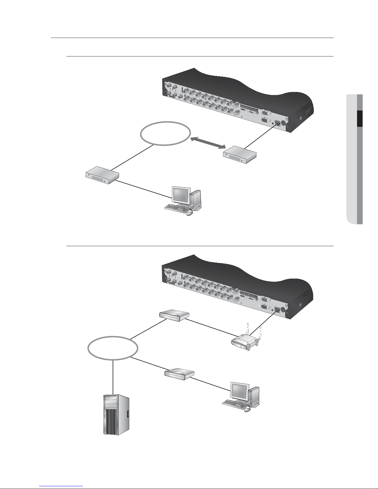
CONNECTING THE NETWORK
Connecting to Network through Ethernet (10/100BaseT)
Connecting to the Network using the router
CONSOLE
AUDIO IN
CH1
CH2
VGA OUT
SERIAL
DC 12V
NETWORK
AUDIO IN
VIDEO IN
VIDEO IN
1
2
13
1
ALARM
OUT
RS48
5
COM
CO
M
2
1
2
3
4
5
6
7
8
9
1
0
1
1
1
4
15
1
6
G
G
ALARM IN
1
2
3
4
5
6
7
8
SPOT
9
10
11
12
13
14
15
16
VIDEO OUT
CH3
CH4
AUDIO OUT
NETWORK
Hub/Switcher
Hub/Switcher
Windows
Network Viewer
RJ-45 Ethernet Cable
(Direct Cable)
Back Bone
CONSOLE
AUDIO IN
CH1
CH2
VGA OUT
SERIAL
DC 12V
NETWORK
AUDIO IN
VIDEO IN
VIDEO IN
12
13
1
ALARM
OUT
RS-
48
5
COM
CO
M
2
1
2
3
4
5
6
7
8
9
1
0
1
1
1
4
15
1
6
G
G
ALARM IN
1
2
3
4
5
6
7
8
SPOT
9
10
11
12
13
14
15
16
VIDEO OUT
CH3
CH4
AUDIO OUT
Broadband Router
xDSL or Cable Modem
NETWORK
External Remote PC
DDNS Server
(Data Center)
xDSL or Cable Modem
16_ connecting with other device
connecting with other device
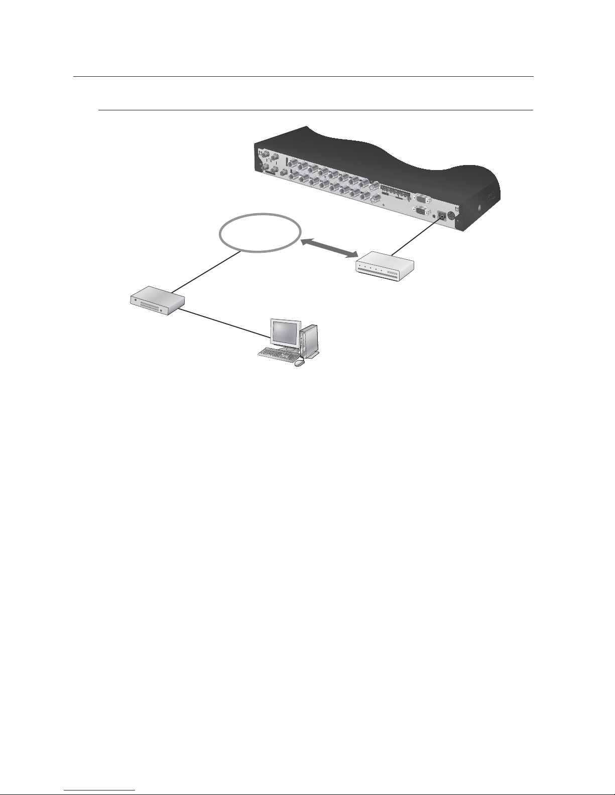
Connecting to Internet through ADSL
CONSOLE
AUDIO IN
CH1
CH2
VGA OUT
SERIAL
DC 12V
NETWORK
AUDIO IN
VIDEO IN
VIDEO IN
12
13
1
ALARM
OUT
RS-
48
5
COM
CO
M
2
1
2
3
4
5
6
7
8
9
1
0
1
1
1
4
15
1
6
G
G
ALARM IN
1
2
3
4
5
6
7
8
SPOT
9
10
11
12
13
14
15
16
VIDEO OUT
CH3
CH4
AUDIO OUT
INTERNET
Hub/Switcher
ADSL MODEM
Windows
Network Viewer
RJ-45 Ethernet Cable
(Direct Cable)
Phone(ADSL) Line
English _17
LIVE
GETTING STARTED
Starting the system
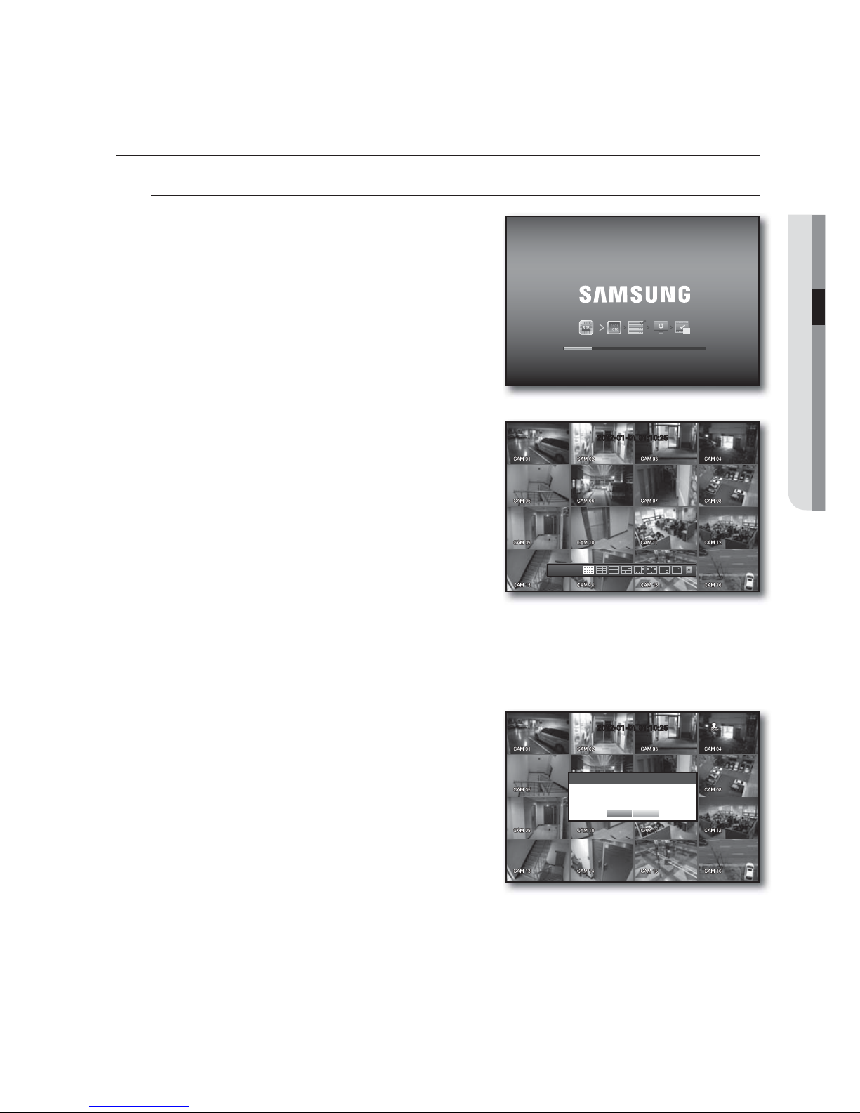
1. Connect the power cable of the DVR to the wall outlet.
M
It takes about 10 seconds to display the start screen after
booting.
2. You will see the initialization screen.
The initialization process will last about 1 minute.
If a new HDD is installed, the initialization process may
take longer.
3. The live screen appears with a beep.
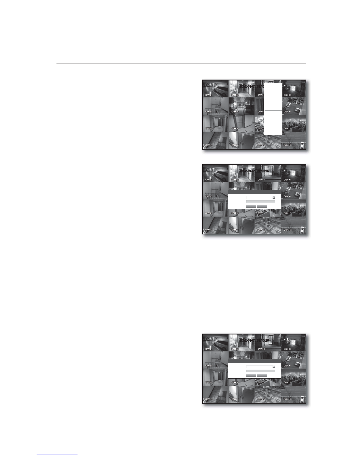
Shutting Down the System
You can shut down the system only if you have logged into the DVR.
You require permission to shut down the system if you are not logged in as admin.
1. Right-click to display the context menu and select
<Shutdown>, or press the [POWER] button on the
remote control.
2. The “Shutdown” confirmation window appears.
3. Use the arrow keys on the remote control to move to
<OK> and press the [ENTER] button or click <OK>.
The system will shut down.
4. Disconnecting the power cable for power off and
reconnecting the power cable to restart.
M
For the permission management, refer to “Permission Management > Setting Permissions”. (Page 33)
live
REC
2012-01-01 01:10:25
2012-01-01
01:10:25
2012-01-01 01:10:25
Shutdown
Are you sure to shutdown?
OK Cancel
18_ live
live
Login
To access a DVR or restricted menu, you should have logged in to the DVR.
1. In live mode, right-click any area of the screen.
You will see the context sensitive menu as in the right
figure.
2. Click <Login>.
The login dialog appears.
You can also see the login dialog to access a desired
menu by pressing the [MENU] button on the remote
control.
The login dialog will also appear if you press a menu button on
the remote control of the DVR when the corresponding menu
requires logging in.
After logged in, press [RETURN] on the remote control to display
the logout dialog.
By default, initial ID and password are set to “admin”, and “4321”.
J
The default password can be exposed to a hacking thread so it is recommended to change the password after
installing the product.
Note that the security and other related issues caused by the unchanged password shall be responsible for the user.
M
For the restricted permission, refer to “Permission Management > Setting Permissions”. (Page 33)
Locking All Buttons
This will restrict access to all buttons available in the DVR.
1. In Live mode, press the remote control buttons in the order
of [STOP (@)]
[FREEZE] [STOP (@)] [FREEZE]
[MENU].
2. In the lock condition, press any button to display a dialog
where you are prompted to enter the password for
unlocking the buttons.
The button lock will be released if you enter the admin
password.
2012-01-01 01:10:25
2012-01-01 01:10:25
Scene Mode
Spot Out
Audio Off
Freeze
Stop Alarm
Record
Play
Search
Backup
Main Menu
Shutdown
Hide Launcher
Login
Login
ID admin
Password
OK Cancel
2012-01-01 01:10:25
Key Lock Password
ID admin
Password
OK Cancel
English _19
LIVE
LIVE SCREEN CONFIGURATION
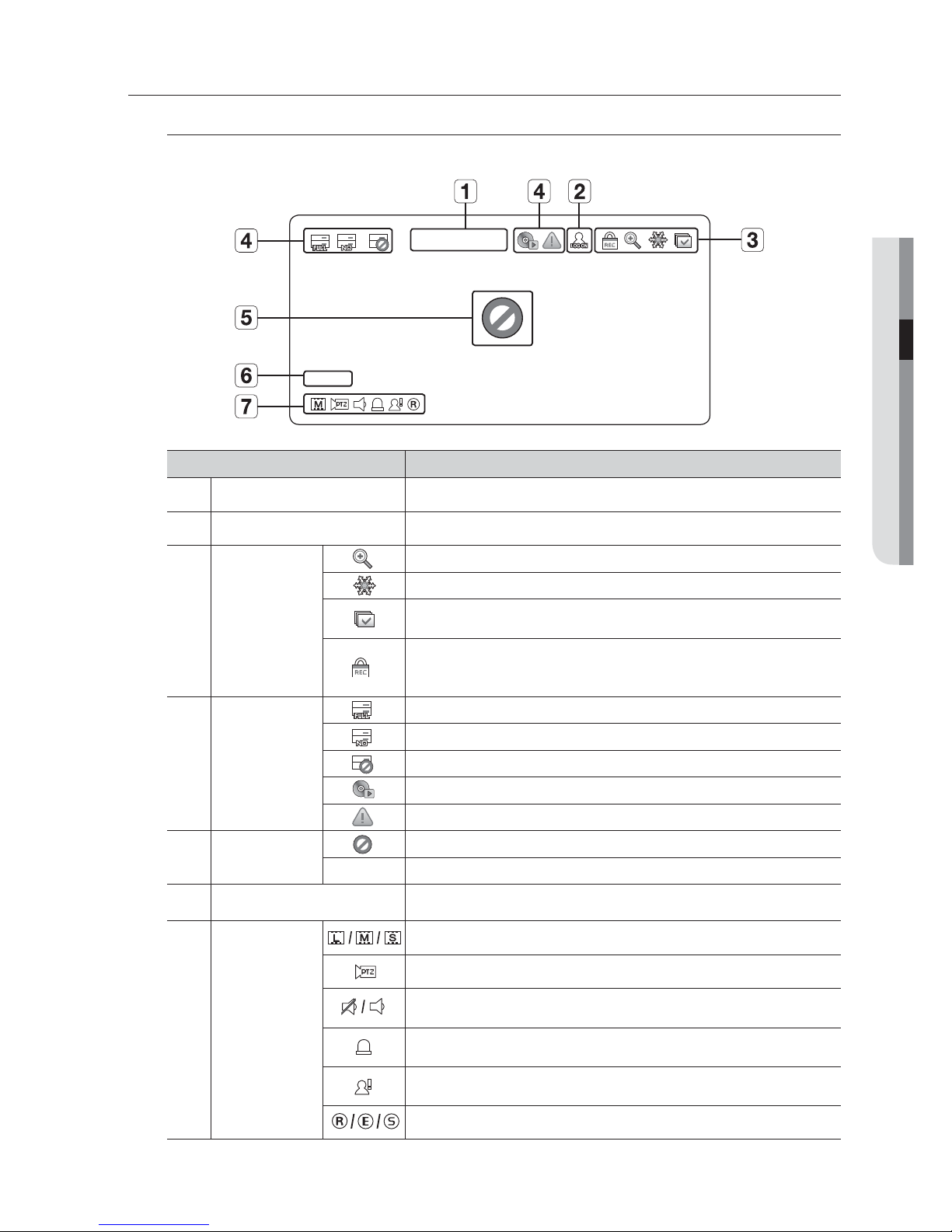
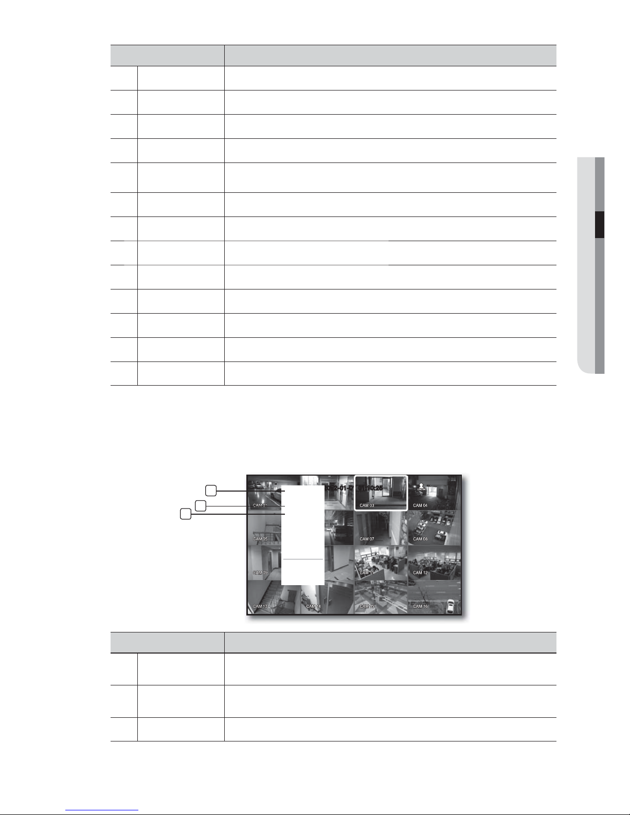
Icons on the Live Screen
You can check the status or operation of the DVR with the icons on the live screen.
Name Description
Current Date, Time
Displays the current time and date.
b
Login Information
When you are logged in, the “LOG ON” icon will be displayed.
c
Screen Mode
Displayed if the zoom function is activated.
Freezes the screen temporarily.
Displayed in Auto Sequence mode where all channels are switched at the specific
time interval.
This icon is displayed if a user with restricted access to the Record button tries to
make manual recording.
Only the user with the applicable permission can release (stop) the recording.
System Operation
Displayed if the HDD is full and the DVR has an insufficient space to record.
Displayed if no HDD is installed or the existing HDD should be replaced.
Displayed if the HDD needs a technical examination.
Displayed while the backup is in process or if the backup data is played.
Displayed if the firmware can be updated via the network.
Video Input Status
Displayed if no input is entered in the condition that the camera is set to <ON>.
Nothing will be displayed on the screen if the camera is set to <OFF>.
Camera Name/ Channel
Displays the camera name and the changed channel, if any.
Camera Operation
Displays the resolution of the recording screen. (Page 47)
Displayed in PTZ setting, and highlighted yellow if PTZ is in operation.
Displays AUDIO ON/MUTE.
Not displayed in video mode if deactivated.
If the sensor is set to <ON>, the input signal will be displayed on the screen of the
connected channel.
Displayed if a motion detected in the condition that the motion detection is set to
<ON>.
Displays the current record mode from Record/Event/Schedule.
CAM 01
CAM 01
2012-01-01 00:00:01
20_ live
live
Error Information
• If the internal HDD is not connected, the “NO HDD”( ) message will appear; if there occurs a problem,
you will see the “HDD FAIL”(
) message in the top left corner. In this case, make sure you contact the
service center for assistance as this may cause a failure of recording, playback or backup.
M
If you see the NO HDD, HDD FAIL icons on the screen, contact the service center for more details.
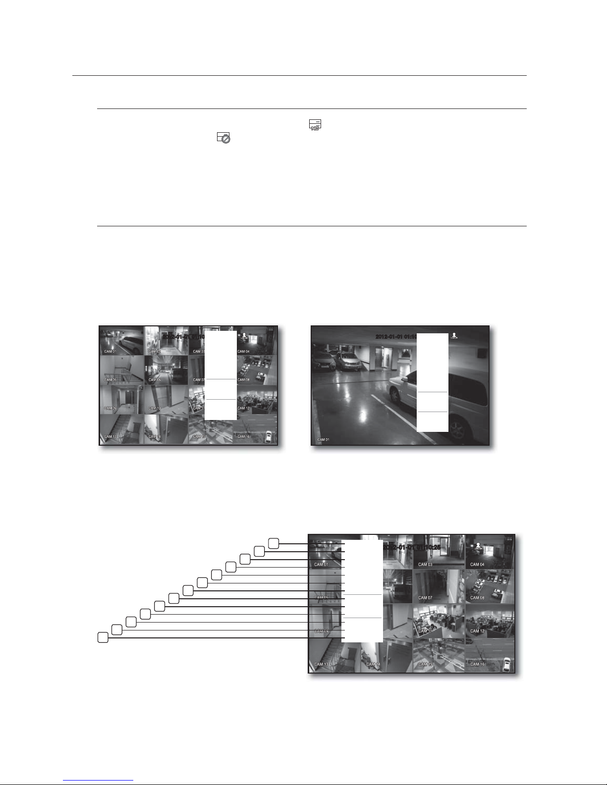
Live Screen Menu
In addition to the buttons the remote control, you can access a desired menu by right-clicking the mouse any
area in live mode.
The context sensitive menu that appears by right-clicking the screen may differ, depending on the login/logout,
screen split mode and DVR operation mode.
M
Menu items of Search, Record, Backup, Shutdown and PTZ can be deactivated, depending on the user permission.
Split Mode Menu
The context sensitive menu in split mode differs, depending on the login/logout status.
< Single Mode Menu >
2012-01-01 01:10:25
Scene Mode
Spot Out
PTZ Control
Zoom In
Audio Off
Freeze
Stop Alarm
Record
Play
Search
Backup
Main Menu
Shutdown
Hide Launcher
Logout
< Split Mode Menu >
2012-01-01 01:10:25
Scene Mode
Spot Out
Audio Off
Freeze
Stop Alarm
Record
Play
Search
Backup
Main Menu
Shutdown
Hide Launcher
Logout
2012-01-01 01:10:25
Scene Mode
Spot Out
Audio Off
Freeze
Stop Alarm
Record
Play
Search
Backup
Main Menu
Shutdown
Hide Launcher
Logout
2
12
13
11
10
9
8
7
6
5
4
3
1
English _21
LIVE
Menu Description
Scene Mode Refer to “Live Mode”. (Page 23)
b
Spot Out Refer to “Spot Out”. (Page 25)
c
Audio On/Off Refer to “Audio ON/OFF”. (Page 26)
Freeze Refer to “Freeze”. (Page 26)
Stop Alarm
Stop the alarm output, deactivate the event icon and release the auto sequencing.
Refer to “Event Monitoring”. (Page
27)
Record/Stop Starts/stops the standard recording.
Play Refer to “Search & Play > Play”. (Page 67)
Search Refer to “Search & Play > Search”. (Page 64)
Backup Refer to “Using the DVR > Setting the Backup”. (Page 52)
Main Menu Accesses the main menu. Refer to the Using the DVR section. (Page 28)
Shutdown Turns down the DVR.
Show/Hide Launcher Shows or hides the launcher. Refer to “View the Launcher Menu”. (Page 22)
m
Login/Logout You can log in or out.
Single Mode Menu
The single mode menu is available only in Single Mode.
The context sensitive menu for the One Channel mode, in Split mode is different from that of the Single mode.
Menu Description
Full Screen
Select and click a desired channel in Split mode to switch to the full screen of the selected
channel.
b
PTZ Control
Accesses the PTZ Control menu.
The PTZ menu will be active on Live screen if you select a single channel. (Page
61)
c
Zoom In Enlarges the selected image. (Page 26)
2012-01-01 01:10:25
Full Screen
Spot Out
PTZ Control
Zoom In
Audio On
Freeze
Stop Alarm
Record
Play
Shutdown
Hide Launcher
Logout
3
2
1
22_ live
live
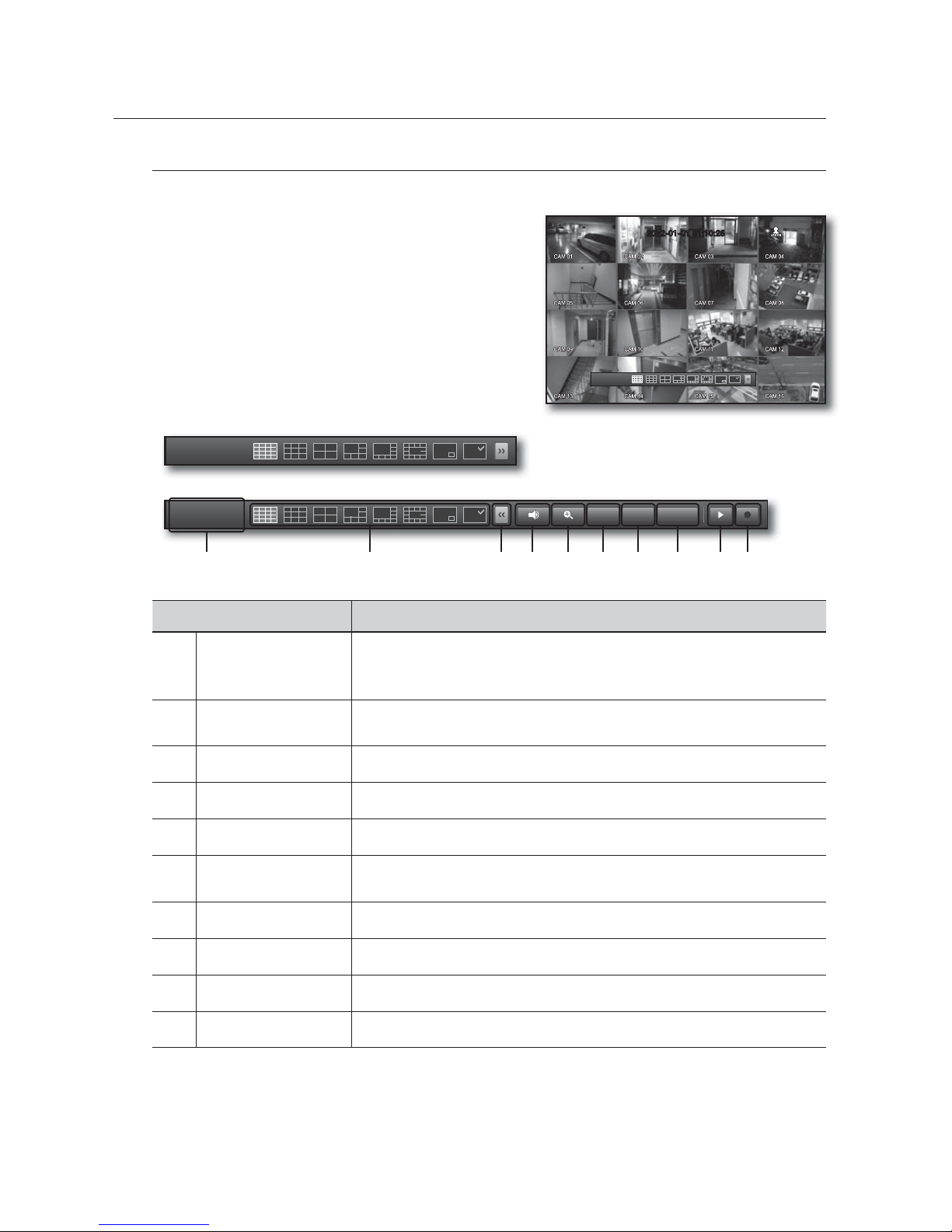
View the Launcher Menu
The Launcher menu appears on the bottom of the live screen.
1. In Live mode, right-click to display the context menu and
select <Show Launcher>.
2. Move the cursor to the bottom and click a desired item in
the Launcher menu.
M
If no input is entered for 10 seconds, the menu will disappear.
The Launcher menu can be accessed only by using the
mouse.
SRD-840 does not support the 16-split screen mode.
Menu Description
Date/Time
Displays the current time and date.
The indication of AM/PM is displayed if you set 12 hours for the time format in “System >
Date/Time/Language > Time”. (Page 28)
b
Screen Mode
Press this button to switch the screen mode in sequence.
The current screen mode will be displayed in white.
c
Menu Expansion Button Click to display the hidden menu to the right.
Audio Turns ON/MUTE the sound of the selected channel.
Zoom Enlarges the selected area. This is available only in Single Live mode.
PTZ
Runs the PTZ Control launcher.
The PTZ control launcher will be active on the Live screen after you select a single channel.
Alarm Stops the alarm if it's activated.
Freeze Freezes the Live screen temporarily.
Play Enters Play mode if a file to play exist, and if not, enters Search mode.
Record Start/End recording the Live screen.
2012-01-01 01:10:25
2012-01-01
01:10:25
2012-01-01
01:10:25
2012-01-01
01:10:25
c b
PTZ
Alarm Freeze
English _23
LIVE
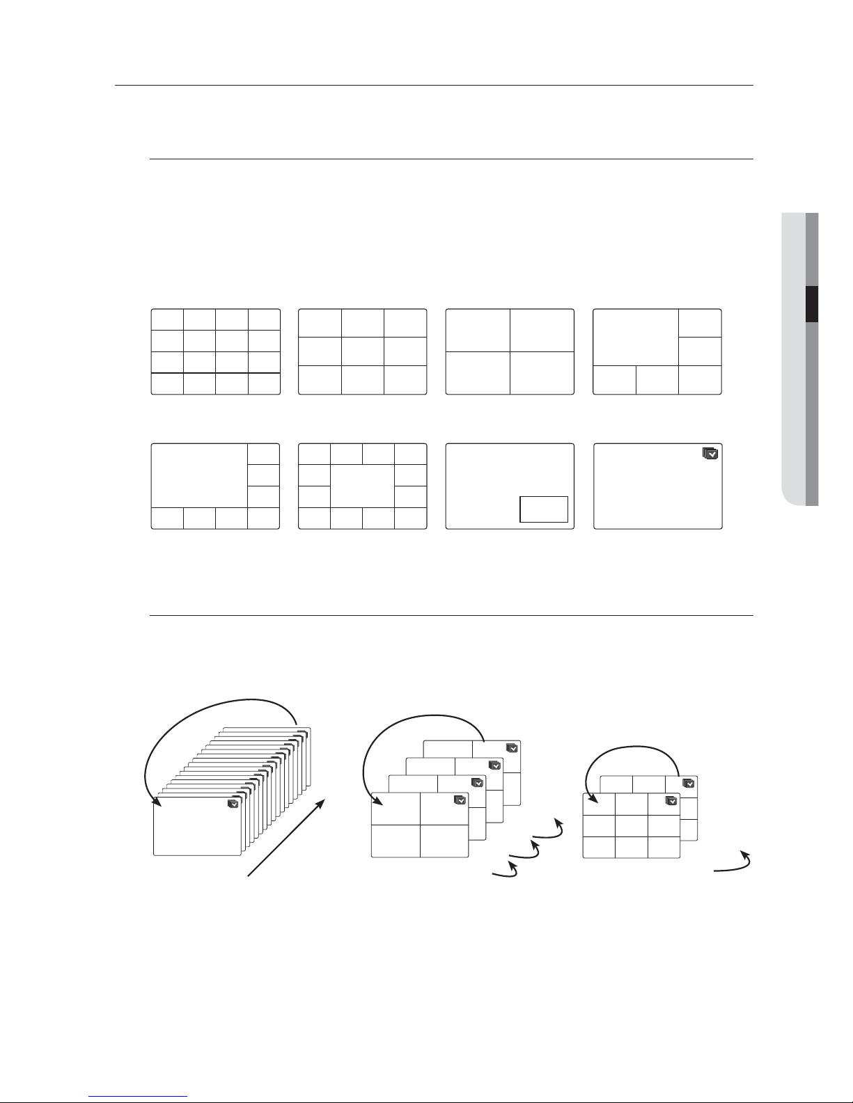
LIVE MODE
SRD-1640
display Live images from 16 channels in a total of 8 layout of split screens.
Switching the screen mode
To switch the split mode, select a screen mode in the launcher menu, or right-click to select a screen mode in
the context menu.
Press the [MODE] button on the remote control to switch the screen mode in the order suggested in the
launcher menu.
M
SRD-840 do not support the 16-split screen mode.
Switching the split mode
SRD-1640 display 16 Live images in the sequence of Single, 4-split and 9-split modes.
Auto Sequence
M
In Single mode, If you have set <SEQ-Dwell Time> in “Setting the Device > Camera”, Auto Sequence will be
conducted at the set interval. (Page 38)
In a split mode, If you have set <Multi CH SEQ Time> in “Setting the Device > Monitor”, Auto Sequence will be
conducted at the set interval. (Page 44)
CH1 CH2
CH3 CH4
CH4 CH5
CH2
CH6
CH1 CH3
CH7 CH8 CH9
CH1 CH3
CH2
CH4 CH5 CH6
CH15
CH11
CH16
CH12
CH7
CH3
CH8
CH4
CH13
CH9
CH14
CH10
CH5
CH1
CH6
CH2
16-split mode 9-split mode 4-split mode 6-split mode
CH1CH7 CH8
CH4
CH3
CH2
CH5
CH1
CH6
CH12
CH1
CH13
CH19
CH4
CH7
CH5
CH10
CH8
CH11
CH6
CH2 CH3
CH1
CH2
8-split mode 13-split mode PIP
Auto Sequence
16
CH1
1
Single mode
CH1
CH1
CH1
CH1
CH1
CH1
CH1
CH1
CH1
CH1
CH1
CH1
CH1
CH1
CH1
CH1
CH1 CH2
CH3 CH4
13-16
9-12
5-8
1-4
4-split mode
CH1 CH2
CH3 CH4
CH1 CH2
CH3 CH4
CH1 CH2
CH3 CH4
CH4 CH5
CH2
CH6
CH1 CH3
CH7 CH8 CH9
10-16
1-9
9-split mode
CH4 CH5
CH2
CH6
CH1 CH3
CH7 CH8 CH9
24_ live
live
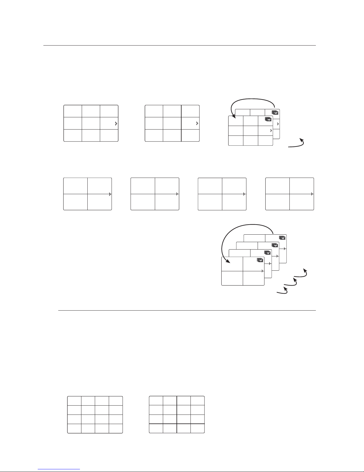
Manual Switching
Press the left/right button on the remote control, or click the arrow <◄/►> key to move to the next split mode.
• If pressing the right [►] button in 9-split mode :
9-split (CH 1~9) mode 9-split (CH 10~16) mode Auto Sequence
• If pressing the right [
►
] button in 4-split mode :
Channel (CH 1~4) Channel (CH 5~8) Channel (CH 9~12) Channel (CH 13~16) Auto Sequence
Channel Setting
You can display the channel in a desired area of a split screen.
1. Place the cursor over the camera name of each channel to display the <
▼
> key to the right on the screen.
2. Click a camera name to display a channel list where you can select a different channel.
3. Select a desired channel and click it.
The current channel will be switched to the selected one.
Use the cursor to select a channel to move, and drag and drop it to a desired channel; this can also
change the channel position.
Ex : if switching CH 1 to CH 7
CH4 CH5
CH2
CH6
CH1 CH3
CH7 CH8 CH9
CH13 CH14
CH11
CH15
CH10 CH12
CH16
CH4 CH5
CH2
CH6
CH1 CH3
CH7 CH8 CH9
CH4 CH5
CH2
CH6
CH1 CH3
CH7 CH8 CH9
10-16
1-9
CH1 CH2
CH3 CH4
CH5 CH6
CH7 CH8
CH9 CH10
CH11 CH12
CH13 CH14
CH15 CH16
CH1 CH2
CH3 CH4
13-16
9-12
5-8
1-4
CH1 CH2
CH3 CH4
CH1 CH2
CH3 CH4
CH1 CH2
CH3 CH4
CH15
CH11
CH16
CH12
CH7
CH3
CH8
CH4
CH13
CH9
CH14
CH10
CH5
CH1
CH6
CH2
CH15
CH11
CH16
CH12
CH1
CH3
CH8
CH4
CH13
CH9
CH14
CH10
CH5
CH7
CH6
CH2
English _25
LIVE
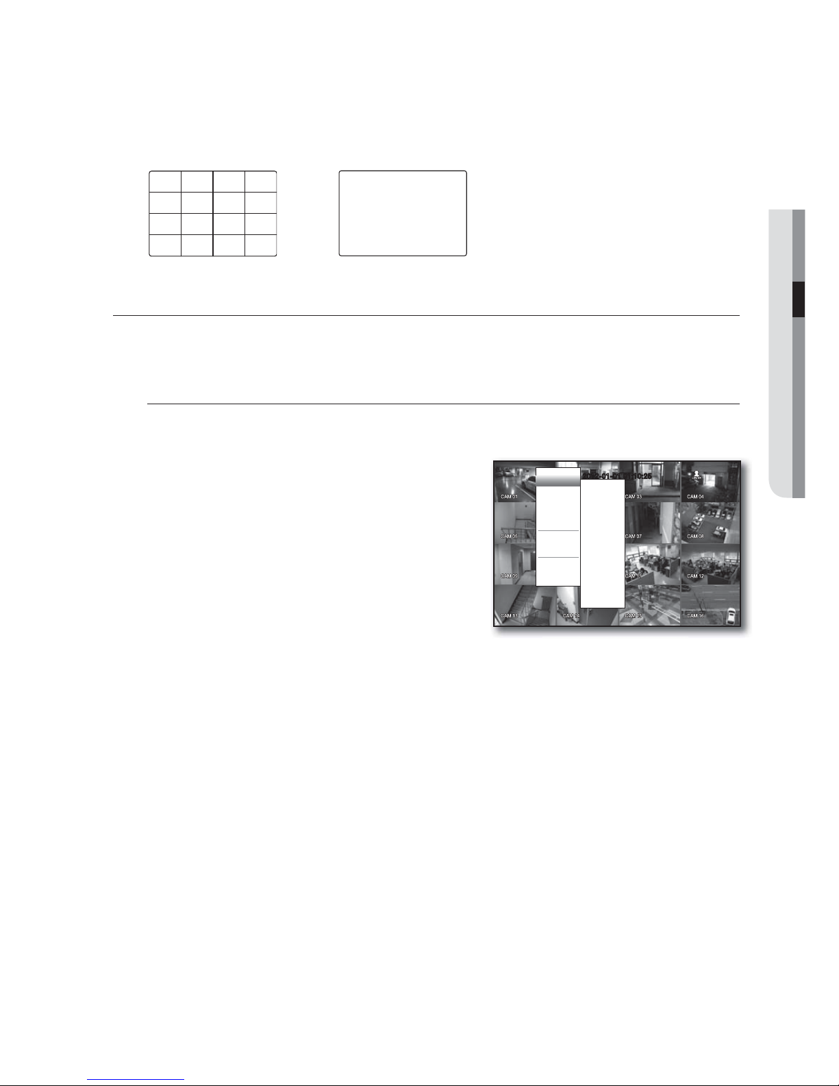
Switching to Single Mode
When in split mode, select and double-click a desired channel to switch to its Single mode.
Press the number corresponding to a desired channel the remote control to switch to its Single mode.
Refer to “Remote Control > Using the numeric buttons”. (Page 11)
Ex : If you click number 3 channel button or press the number 3 on the remote control.
SPOT OUT
The Spot Out monitoring is independent of the Live mode, which monitors a specific channel through the Spot Out
port.
Selecting a Spot Out mode
If an event occurs such as sensor, motion or alarm from the Spot Out port in connection with a monitor, you
can select a output screen mode.
1. In Live mode, right-click any area on the screen.
The Live menu appears.
2. Click <Spot Out>.
Supports the Spot output in Single screen with Auto
Sequence mode.
If the monitor is connected to the Spot port, the event that
occurred from the selected channel will be output on the
monitor.
For the Spot Out port of a model, refer to “Part Names and
Functions (Rear)”. (Page 10)
< Multichannel Live Menu >
2012-01-01 01:10:25
Auto Sequence
CH1
CH2
CH3
CH4
CH5
CH6
CH7
CH8
CH9
CH10
CH11
CH12
CH13
CH14
CH15
CH16
Scene Mode
Spot Out
Audio Off
Freeze
Stop Alarm
Record
Play
Search
Backup
Main Menu
Shutdown
Hide Launcher
Logout
CH15
CH11
CH16
CH12
CH7
CH3
CH8
CH4
CH13
CH9
CH14
CH10
CH5
CH1
CH6
CH2
CH3
26_ live
live
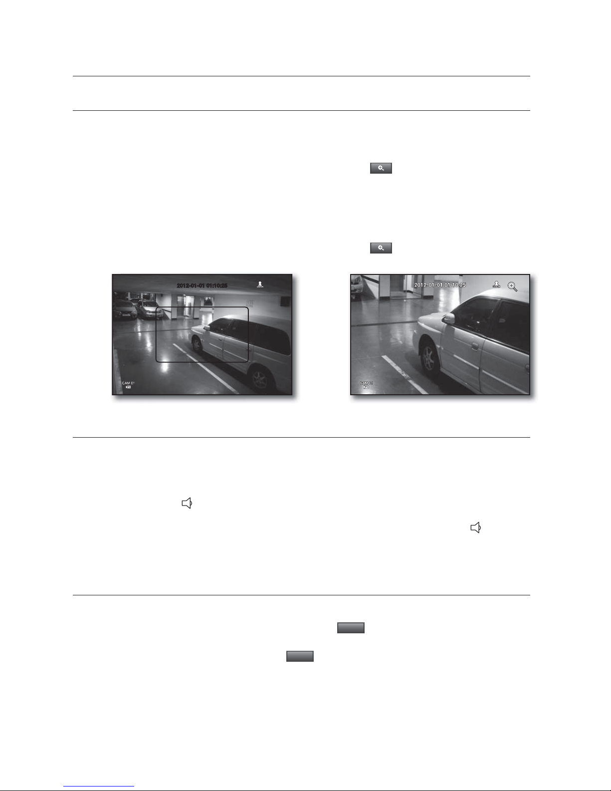
ZOOM
This is available only in Single Live mode. In Single mode, select a desired area and use the Zoom function to
enlarge it twice.
1. Select <Zoom In> in the right-click menu.
Press the [ZOOM] button on the remote control, or simply click < > in the launcher menu. The zoom
box appears.
2. Use the direction keys, or drag and drop to specify an area to enlarge.
3. Press the [ENTER] button, or double-click the selected area to enlarge it twice.
In the enlarged image, use the direction buttons (◄ ►) on the remote controlto move the enlarged area.
4. Press the [ZOOM] button on the remote control, or simply click < > in the launcher menu to release
the zoom.
AUDIO ON/OFF
In Live mode, you can selectively turn on/off the sound from each channel.
AUDIO ON/OFF in Single mode
Click the audio icon ( ) on the screen, or press the [AUDIO] button on the remote control to turn it on/off.
M
Only the channel where <AUDIO> is set to <ON> in “Device > Camera” displays the audio icon ( ) in Live mode
that you can use to turn the sound on/off.
FREEZE
This is available only in Live mode, this pauses playing the Live image temporarily.
1. Press the [FREEZE] button the remote control, or click <
Freeze
> in the launcher menu.
The playback of the image is stopped temporarily.
2. Press the [FREEZE] button again, or click <
Freeze
>.
This will release the freeze.
2012-01-01 01:10:252012-01-01 01:10:25
English _27
LIVE
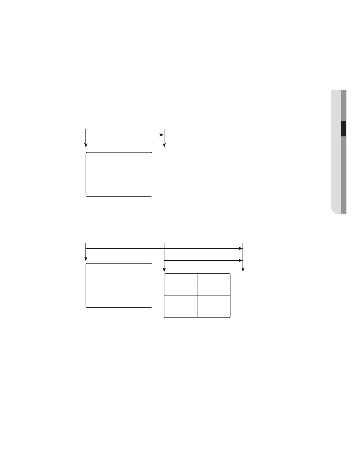
EVENT MONITORING
This will display the channel in sync with a specific event (Sensor/Motion/Video Loss) if it occurs.
In “Monitor > Event Display”, set the event monitoring to ON/OFF and specify the event display time. (Page 44)
• If multiple events occur simultaneously, the screen will switch to a split mode.
- 2~4 events : 4-split mode
- 5~9 events : 9-split mode
- 10~16 events : 16-split mode
• If the second event occurs within the set time of <Event Display>, the first event will last until the second
one is terminated. (Page 44)
Ex : If you set <Event Display> to 5 seconds, and only one event occurs in CH 1.
Ex : If you set <Event Display> to 5 seconds, and the second event occurs in CH 2 within the set time after the first
event occurred in CH 1.
M
Press the [ALARM] button to reset the alarm settings and to release the event mode.
If an alarm activates in the condition you have set the event record, and pre/post alarm times, the event record will
be performed.
This will also apply to the Spot Out monitor.
J
If such as motion events occur consecutively, and you stop the event alarm but another event occurs, it may not
work properly to switch the split mode or manipulate the menus.
CH1
Event occurrence 5 seconds
Stop alarm
CH1 CH2
CH1
Event occurrence 4 seconds 9 seconds
Stop alarm
28_ using the DVR
You can setup the system properties, devices, and options for recording, event,
backup and network.
SYSTEM SETUP
You can setup Date/Time/Language, Permission, System Properties and Log.
Date/Time/Language
You can check and setup the current Date/Time and time related properties, as well as the language used for
the interface on the screen.
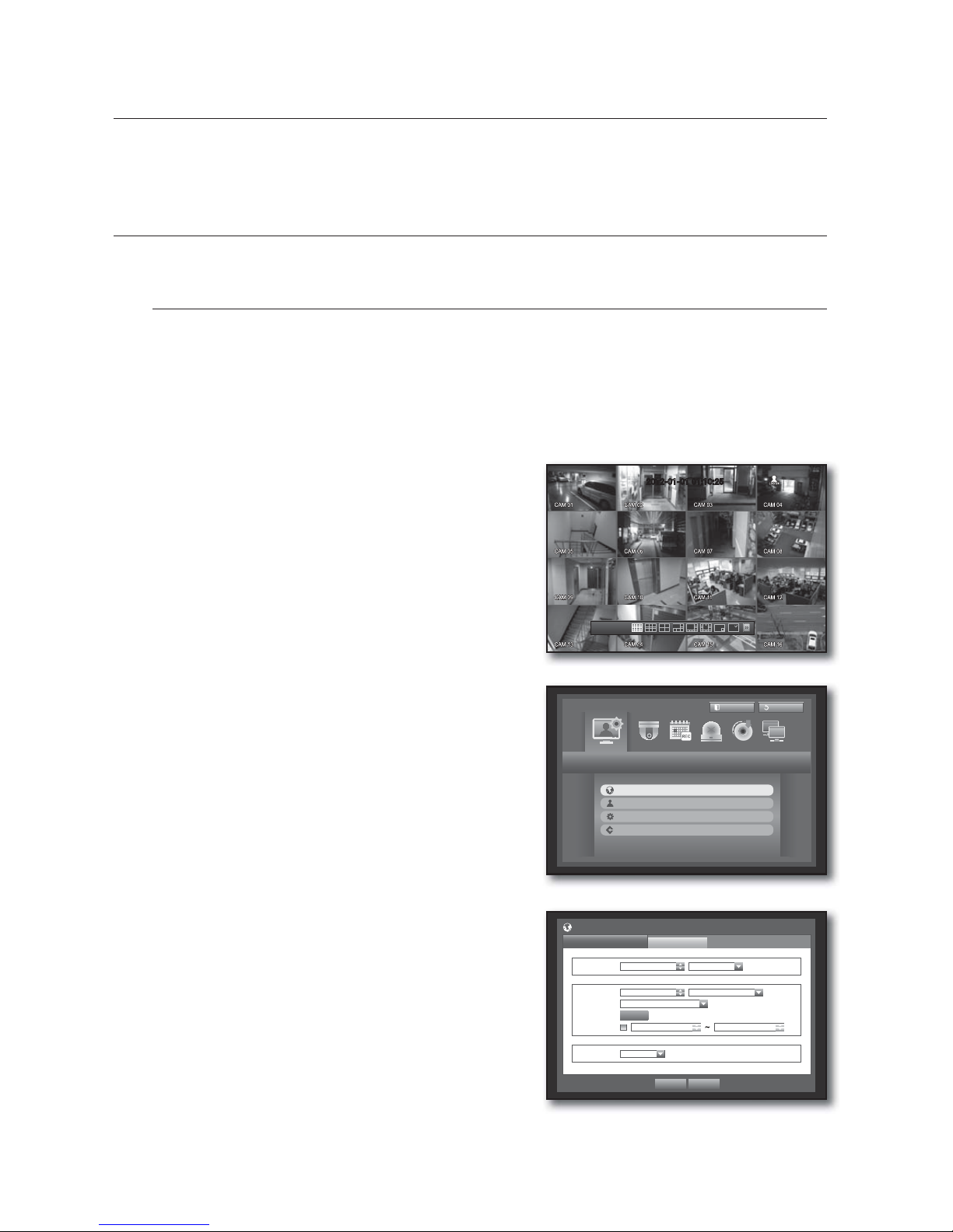
Setting the Date/Time/Language
Set the Date/Time/Language
Using the mouse may help make setup easier.
1. Press the [MENU] button on the remote control.
If not logged in, it prompts with login window.
Refer to “Login”. (Page 18)
2. Use the left/right buttons (
◄ ►
) to select the <System>.
System property setup menu is selected.
3. Use the up/down buttons (
) to select <Date/Time/
Language> and press the [ENTER] button.
4. Select <Date/Time/Language>.
A dialog to setup Date, Time and Language.
5. Use direction buttons (
◄ ►
) to select an item to set
and make your changes.
• Date : Sets the date that will appear on the screen.
You can select the date format.
• Time : Sets the time and its format that will appear on the
screen.
Select either one from <24 Hours, 12 Hours (AM/PM)>.
• Time Zone : Sets the time zone of your area based on the
Greenwich Mean Time (GMT).
GMT (Greenwich Mean Time) is standard World Time and the basis
of world time zone.
• Time Sync. : You can set the DVR’s current time
synchronized to a selected <Time Server> regularly if you select to use <Time Server>.
In this case, <Date/Time/Language> setup does not allow time adjustment.
using the DVR
System
Logout
Return
Date/Time/Language
Permission Management
System Management
Log Information
Date/Time/Language
Date/Time/Language
Holiday
Date
2012-01-01 YYYY-MM-DD
Time 08:14:24 24 Hours
Time Zone GMT
Time Sync.
Setup
DST
Dec First (Sun) 0 Dec First (Sun) 0
Language English
OK Cancel
2012-01-01 01:10:25
2012-01-01
01:10:25
English _29
USING THE DVR
- Time Server : Enter an IP or URL address of the time
server.
- Last Sync Time : Displays the most recent
synchronization time from the selected time server.
- Activate as Server : Set to <Use> to allow the DVR to act
as a Time Server for other DVRs.
• DST : Set up Daylight Saving Time with its period to make
the time earlier than the GMT of its time zone by 1 hour
during the set period.
• Language : Select your language. Sets the language for the
interface.
English, French, German, Spanish, Italian, Chinese, Russian, Korean, Polish, Japanese, Dutch, Portuguese,
Turkish, Czech, Danish, Swedish, Thai, Romanian, Serbian, Croatian, Hungarian and Greek are available.
6. When the Date/Time/Language setup is done, press <OK>.
M
You can also use numeric buttons on the remote control to enter values for Date, Time and other numeric fields.
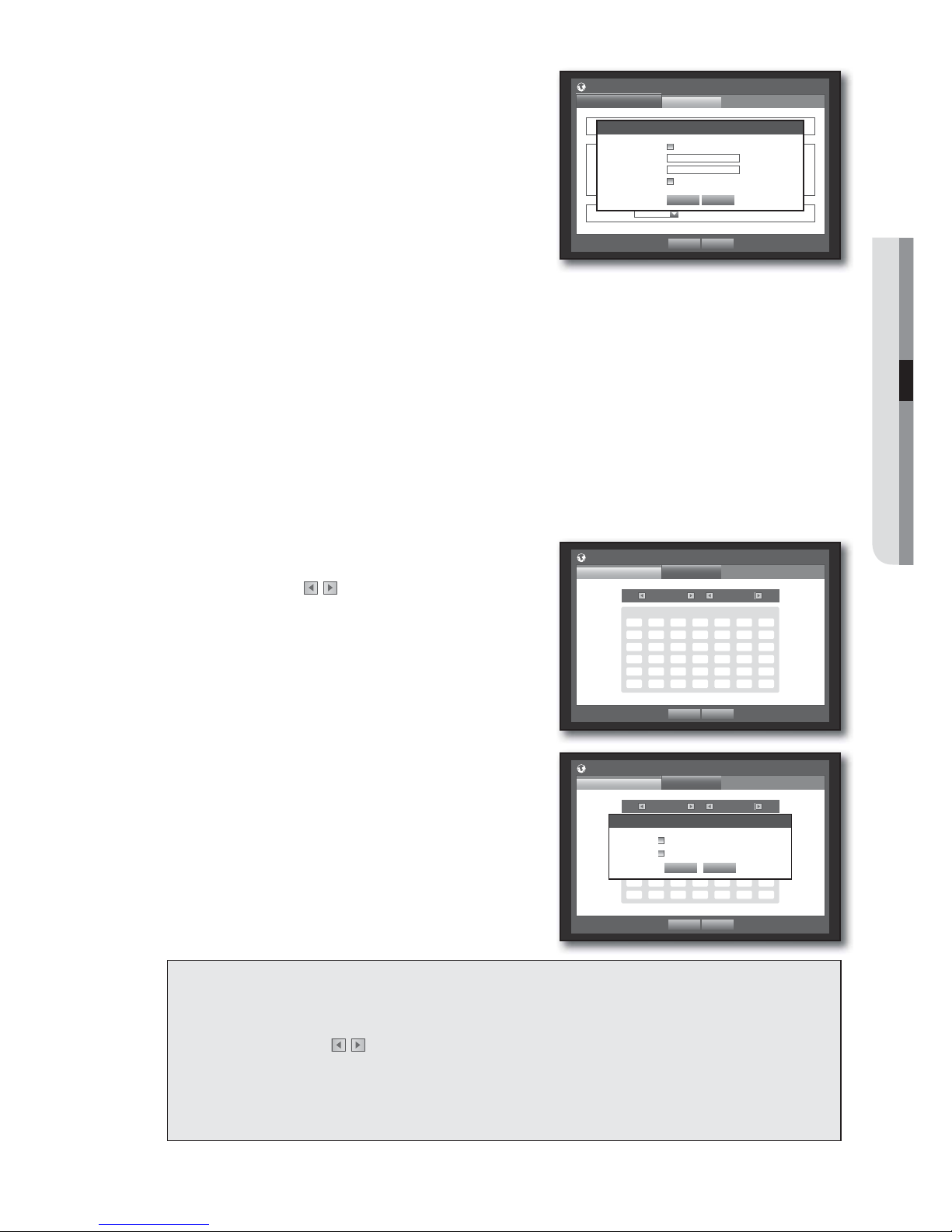
Setting Holiday
You can set specific dates to Holidays according to your preferences.
Holidays are applied to <Recording Schedule> and <Alarm Schedule> too.
Using the mouse may help make setup easier.
1. Use the up/down buttons () in <Date/Time/Language> window to select <Date/Time/Language>, and
press the [ENTER] button.
2. Select <Holiday>.
A calendar for Holiday setup appears.
3. Use the left/right <
> buttons to select year or month,
and press the [ENTER] button.
4. Use direction buttons (
◄ ►
) to select a desired date,
and press the [ENTER] button.
You will see the “Setting Holiday” screen.
Ex : Select January 9th and check on <1/9> only to make every
January 9th a holiday. Check both on <1/9> and <Jan 2nd
Mon> to make every January 9th and 2nd Monday of January
holidays.
5. When the Holiday setup is done, press <OK>.
Using the Calendar
Using the mouse may help make setup easier.
{
Select year and month.
Select the left/right < > key on the left/right side of year/month and press [ENTER] button to
adjust by 1 year/month.
|
Use direction buttons to select a date and press [ENTER] button.
A date with recorded data to be searched will appear in yellow in the System Log, Event Log, Time Search and Event
Search.
Date/Time/Language
Date/Time/Language
Holiday
Date
2012 -01-01 YYYY-MM-DD
Time 08:14:24 24 Hours
Time Zone GMT+08:00
Time Sync.
Setup Not Used
DST
Dec First (Sun) 0H Dec First (Sun) 0H
Language English
OK Cancel
Time Synchronization Setup
OK Cancel
Synchronization Use
Time Server 203.248.240.103
Last Sync Time Fail
Activate as Server Use
OK Cancel
Date/Time/Language
Date/Time/Language
Holiday
2012 Jan
Sun Mon Tue Wed Thu Fri Sat
1 2 3 4 5 6 7
8 9 10 11 12 13 14
15 16 17 18 19 20 21
22 23 24 25 26 27 28
29 30 31
OK Cancel
Date/Time/Language
Date/Time/Language
Holiday
2012 Jan
Sun Mon Tue Wed Thu Fri Sat
1 2 3 4 5 6 7
8 9 10 11 12 13 14
15 16 17 18 19 20 21
22 23 24 25 26 27 28
29 30 31
Setting Holiday
OK Cancel
1 / 9
Jan 2nd Mon
30_ using the DVR
using the DVR
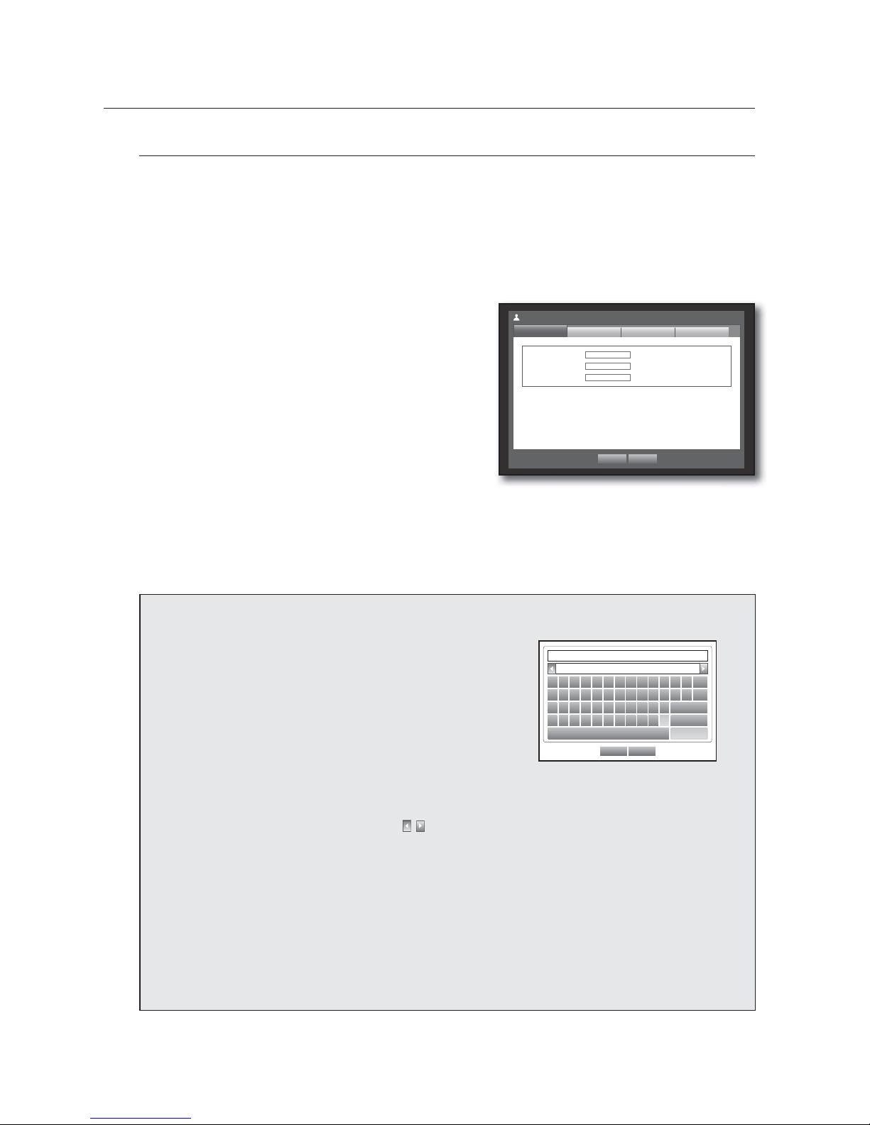
Permission Management
You can set permissions of each user over the DVR's specific function and settings.
Setting the Administrator
You can set and change Administrator’s ID and password.
The administrator can use and set all menu items and functions.
Using the mouse may help make setup easier.
1. Use the up/down buttons () in <System> window to
move to <Permission Management>, and press
[ENTER] button.
2. Select <Admin>.
A dialog for Admin ID and Password input appears.
3. Use direction buttons (
◄ ►
) to move to a desired
item, and set the ID and password.
M
By default, initial ID and password are set to “admin”, and
“4321”.
The default password can be exposed to a hacking thread so it is recommended to change the password after
installing the product.
Note that the security and other related issues caused by the unchanged password shall be responsible for the user.
4. When the administrator setup is done, press <OK>.
Using Virtual Keyboard
{
For alphanumeric inputs, the virtual keyboard window
appears.
|
Use direction buttons (
◄ ►
) to move to a desired
character, and press the [ENTER] button.
}
In the upper text input box of the virtual keyboard, there
displays a list of candidate words containing the selected
character.
~
Select a word from the list, or use the keyboard to enter the
whole word.
OK Cancel
` 1 2 3 4 5 6 7 8 9 0 - =
q w e r t y u i o p [ ] \
Del
a s d f g h j k l ; ‘
Caps Lock
z x c v b n m , . /
Shift
Space Ctrl
If there are many of candidate words, use < , > buttons to move between them forward and backward.
Select <OK>.
Entered word is applied.
For upper case letters, use <Caps Lock> button.
For special characters, use <Shift> button.
Using the virtual keyboard is the same to a normal keyboard use in your region.
You can type the ID with alphanumeric characters only.
For the password, use alphabets and special characters excluding <
\
> and <“>.
You can use number buttons on the remote control.
ID admin
New Password
************
Confi rm P/W
************
Permission Management
Admin
Group
OK Cancel
User Setup
 Loading...