

Samsung AVXCSH023CE, AVXWNH060CE, AVXCSH032CE, AVXCSH040CE, AVXC4H052CE Service Manual
...
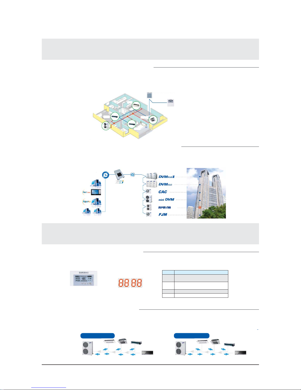
SYSTEM AIR CONDITIONER
INDOOR UNIT
AVXCSH023/032/040CE
AVXC4H052/072/100/110/145CE
AVXCMH032/040/052/060CE
AVXDSH020/032/040/052/072/100/110/145CE
AVXDUH100/110/145CE
AVXWVH020/032/040/052/060CE
AVXWNH020/032/040/052/060CE
ND023/032/0401HXCA
ND052/072/100/1454HXCA
ND032/040/052/060MHXCA
ND020/032/040/052/072/100/110/145LHXCA
ND100/110/145SHXCA
ND220/280HHXCE(CA)
ND020/032/040/052/060VHXCA
ND020/032/040/052/060NHXCA
ND052/072CHXCA
ND020/032/040/052/060QHXCA
ND052/072/100/110/1454HXCB
OUTDOOR UNIT
RVXVHT075/100/125FE
RD040/050MHXCA
RD075/100/125VHXFA
RD075/100/125VRXFA
AIR CONDITIONER CONTENTS
1. Precautions
2. Product Specifications
3. Disassembly and Reassembly
4. Troubleshooting
5. Exploded Views and Parts List
6. PCB Diagram and Parts List
7. Wiring Diagram
8. Schematic Diagram
9. Reference Sheet
Refer to the service manual in the GSPN(see the rear cover) for the more information.

Contents
1. Precautions
1-1 Precautions for the Service ························································································································· 1-1
1-2 Precautions for the Static Electricity and PL ························································································ 1-1
1-3 Precautions for the Safety ··························································································································· 1-2
1-4 Others ·································································································································································· 1-2
2. Product Specifications
2-1 The Feature of Product ································································································································· 2-1
2-1-1 Feature ··················································································································································· 2-1
2-1-2 Changes in comparison to basic model ··················································································· 2-22
2-2 Product Specifications ·································································································································· 2-24
2-2-1 Indoor Unit ··········································································································································· 2-24
2-2-2 Outdoor Unit ······································································································································· 2-47
2-3 Accessory and Option Specifications ····································································································· 2-50
2-3-1 Accessories ··········································································································································· 2-50
3. Disassembly and Reassembly
3-1 Indoor Unit ························································································································································ 3-2
3-2 Outdoor Unit ···················································································································································· 3-11
·························································································································································· 1-1
······························································································································ 2-1
············································································································ 3-1
4. Troubleshooting
4-1 Setting Option Setup Method ·················································································································· 4-1
4-1-1 PCB option code input method ·································································································· 4-1
4-1-2 Setting an indoor unit address and installation option ···················································· 4-11
4-1-3 Option Items ········································································································································ 4-17
4-2 What to check before diagnosis ··············································································································· 4-19
4-2-1 Lamp combination expression method display (cassette type indoor unit) ··········· 4-19
4-2-2
4-3 How to take measures for each symptom
(Model : RVXVHT075/100/125FE, RD075/100/125VHXFA) ···························································· 4-31
4-3-1 Outdoor unit operation flow ········································································································ 4-36
4-3-2 Indoor Unit ROOM sensor Error (Open/Short) ······································································ 4-40
4-3-3 Indoor unit EVAP IN sensor Error (Open/Short) ···································································· 4-41
4-3-4 Indoor EVAP OUT sensor Error (Open/Short) ········································································· 4-42
4-3-5 Indoor heat exchanger’s EVAP IN sensor dislocation error ·············································· 4-43
4-3-6 Indoor Heat Exchanger’s EVA OUT sensor dislocation error (Open/Short) ··············· 4-44
4-3-7
4-3-8 Operational error of indoor Unit’s Clean Fan (Open/Short) ············································· 4-46
Numeric type display(outdoor unit, Wired remote controller, wall-mount type etc.)
Simultaneous Indoor heat exchanger’s EVA IN, OUT sensor dislocation error (Open/Short)
·············································································································································· 4-1
··· 4-29
··· 4-45

Contents
4-3-9 Breakdown of EEV (2nd) ··················································································································· 4-47
nd
4-3-10 Problem with EEV closure (2
4-3-11
4-3-12 The operational error of Indoor Unit’s Fan Motor ······························································ 4-50
4-3-13 EEPROM error ···································································································································· 4-51
4-3-14 Option error of the Remote Controller for an Indoor Unit ············································ 4-52
4-3-15 Error due to confused use of Fahrenheit and Celsius ······················································ 4-53
4-3-16 Error due to incorrect Indoor Unit Power/Communication Cable Connection ···· 4-54
4-3-17 SPi Feedback Error ·························································································································· 4-55
4-3-18 Communication error between Indoor and Outdoor units during Tracking ········· 4-56
4-3-19
4-3-20 Communication error between Main and Sub Micoms of an Outdoor unit or
4-3-21 Outdoor Temperature Sensor error ························································································· 4-60
4-3-22 Outdoor Temperature dislocation error ················································································ 4-61
4-3-23 COND OUT Temperature Sensor error (Open/Short) ······················································· 4-62
4-3-24 Outdoor COND OUT Sensor dislocation error ···································································· 4-63
4-3-25 Discharge Temperature Sensor error for a digital Compressor (Open/Short) ······· 4-64
4-3-26
4-3-27 Compressor’s Discharge Temperature Sensor dislocation error ································· 4-66
4-3-28
4-3-29
4-3-30 SUMP Temperature Sensor error (Open/Short) ·································································· 4-69
4-3-31 High Pressure Temperature Sensor error (Open/Short) ·················································· 4-70
4-3-32 Low Ppressure Temperature Sensor error (Open/Short) ················································ 4-70
4-3-33 Oil Balance Valve Temp. Sensor error (Open/Short) ························································ 4-71
4-3-34 SUCTION Temperature Sensor error (Open/Short) ··························································· 4-72
4-3-35 Double pipe temperature sensor error ·················································································· 4-73
4-3-36 Main Cooling Sol Valve Open Error ·························································································· 4-74
4-3-37 EVI IN Temperature Sensor error (Open/Short) ·································································· 4-75
4-3-38 EVI OUT Temperature Sensor error (Open/Short) ······························································ 4-76
4-3-39
4-3-40
4-3-41 Protection Control by Sump Sensor Error ············································································· 4-79
4-3-42
4-3-43 3 Detection of phase negative voltage sequence, Phase fail ······································· 4-81
4-3-44
4-3-45
4-3-46 EVI EEV Open Error ························································································································· 4-84
: Detection of Floating Switch of Indoor Unit’s Drain Pump ·························· 4-49
Communication error between Indoor & Outdoor units after Completing Tracking
among Outdoor Units ··················································································································· 4-59
Discharge Temperature Sensor error for a fixed scroll Compressor (Open/Short)
:
Dislocation error of Compressor SUMP Temperature (oil temperature) Sensor
: Dislocation error of Suction Temperature Sensor ············································· 4-68
: Comp. Down due to a Protective Control of High pressure ························· 4-77
: Comp. Down due to a Protective Control of Low Pressure ·························· 4-77
: Comp. Down due to Discharge Temperature Sensor of a Compressor ··· 4-80
: Comp. Down due to compression rate control ················································· 4-82
:
Self-diagnosis of Oil valve(balance keeping valve) 1(open or closure
breakdown, sensor dislocation or defect)
) ·································································································· 4-48
··· 4-58
··· 4-65
··· 4-67
···························································· 4-83

Contents
4-3-47 , : Prohibition of the operation of Compressor due to
OoutdoorTemperature ·················································································· 4-85
4-3-48 High Pressure below the Average before Cooling (Unable to Restart) ···················· 4-86
4-3-49 Instantaneous Blackout ················································································································ 4-87
4-3-50 Error by High Temperature in an Outdoor Fan Motor ····················································· 4-87
4-3-51 RPM Error of an Outdoor Fan Motor ······················································································· 4-87
4-3-52 Over-Voltage Error of an Outdoor Fan Motor ····································································· 4-88
4-3-53 Counter-Rotation Error of an Outdoor Fan motor ···························································· 4-88
4-3-54
4-3-55
4-3-56 Liquid Compressor Protection Control ·················································································· 4-91
4-3-57 Breakdown of an EEV(1
4-3-58 Breakdown of an EEV closure(1
4-4 How to take measures for each symptom(Model : RD040/050MHXCA)
4-4-1 Indoor Unit ROOM sensor Error (Open/Short)
4-4-2 Indoor unit EVAP IN sensor Error (Open/Short)
4-4-3 Indoor EVAP OUT sensor Error (Open/Short)
4-4-4 Indoor Heat Exchanger’s EVAP IN sensor dislocation error
4-4-5 Indoor Heat Exchanger’s EVA OUT sensor dislocation error (Open/Short)
4-4-6
4-4-7
4-4-8
4-4-9
4-4-10
4-4-11
4-4-12 EEPROM error
4-4-13 Option error of the Remote Controller for an Indoor Unit
4-4-14 Error due to confused use of Fahrenheit and Celsius
4-4-15 Error due to incorrect Indoor Unit Power/Communication Cable Connection
4-4-16 Communication error between Indoor and Outdoor units during Tracking
4-4-17
4-4-18 Communication error between main PCB and inverter PCB during Tracking
4-4-19 Outdoor Temperature Sensor error
4-4-20 COND OUT Temperature Sensor error (Open/Short)
4-4-21
4-4-22 Discharge Temperature Sensor error (Open/Short)
4-4-23
4-4-24 High Pressure Temperature Sensor error (Open/Short)
4-4-25 Double pipe temperature sensor error(Open/Short)
4-4-26 OLP sensor error (Open/Short)
: Over-voltage error of Compressor ·········································································· 4-89
: Low-amperage error of Compressor ······································································ 4-90
st
) ············································································································· 4-92
st
) ····························································································· 4-93
································
·····································································
···································································
········································································
·············································
···············
:
Simultaneous Indoor Heat Exchanger’s EVA IN, OUT sensor dislocation error (Open/Short)
: Breakdown of EEV (2nd)
: Problem with EEV closure (2nd)
: Detection of Floating Switch of Indoor Unit’s Drain Pump
: The operational error of Indoor Unit’s Fan Motor
: Mixed operation Error
··································································································································
································································································
··················································································
····························
············································
·································································································
············································
·····················································
········
Communication error between Indoor & Outdoor units after Completing Tracking
························································································
······················································
: Outdoor COND OUT Sensor dislocation error
: Compressor’s Discharge Temperature Sensor dislocation error
································································································
···················································
·························································
················
·················································
······················································
······
····
····
···
4-94
4-97
4-98
4-99
4-100
4-101
4-102
4-103
4-104
4-105
4-106
4-107
4-108
4-109
4-109
4-109
4-110
4-111
4-112
4-113
4-114
4-115
4-116
4-117
4-118
4-119
4-120

Contents
4-4-27 : Freezing control causes comp. down
4-4-28
4-4-29
4-4-30
4-4-31
4-4-32
4-4-33
4-4-34
4-4-35
4-4-36
5. Exploded Views and Parts List
: High voltage protection compressor stopped
: Compressor down by low pressure sensor protection control
: Dischase temperature sensor error
, , :
Abnormal outside temperature halts operation of the compressor
: Current protection control causes comp. down
: OLP protection control caused comp. down
, : Electrical malfunctions of the outdoor machine
: EEV Off-malfunctions (1st)
: EEV Off inefficiently (1st)
·························································································
·····························································································
·········································································································· 5-1
···································································
··················································
··················
·······································································
···
···············································
·····················································
······························
4-121
4-122
4-123
4-124
4-125
4-125
4-126
4-127
4-128
4-128
5-1 Indoor Unit ························································································································································ 5-1
5-1-1 Slim 1 way cassette type ················································································································· 5-1
5-1-2 Mini 4 way cassette type ················································································································ 5-7
5-1-3 4 way cassette type ··························································································································· 5-11
5-1-4 Globel 4 way cassette type ············································································································ 5-17
5-1-5 Duct type(Slim I) ································································································································· 5-23
5-1-6 Duct type(Slim II) ······························································································································· 5-25
5-1-7 Duct type(Slim III) ······························································································································ 5-27
5-1-8 Duct type(MSP) ··································································································································· 5-29
5-1-9 Duct type(BIG) ····································································································································· 5-33
5-1-10 Wall-mounted type(Vivace) ········································································································ 5-35
5-1-11 Wall-mounted type(Neo Forte without EEV) ······································································· 5-39
5-1-12 Wall-mounted type(Neo Forte with EEV) ·············································································· 5-43
5-1-13 Ceiling type ········································································································································· 5-47
5-2 Outdoor Unit ···················································································································································· 5-51
5-2-1 RVXVHT075/100FE, RD075/100VHXFA ····················································································· 5-51
5-2-2 RVXVHT125FE, RD125VHXFA ········································································································ 5-55
5-2-3 RD075/100VRXFA ······························································································································· 5-59
5-2-4 RD125VRXFA ········································································································································ 5-63
5-2-5 RD040/050MHXCA ···························································································································· 5-67
6. PCB Diagram
6-1 Indoor Unit ························································································································································ 6-1
6-1-1 Slim 1 way cassette type ················································································································· 6-1
6-1-2 4 way cassette type ··························································································································· 6-3
6-1-3 Mini 4 way cassette type ················································································································ 6-4
6-1-4 Duct type(Slim) ··································································································································· 6-5
······················································································································································· 6-1

Contents
6-1-5 Duct type(MSP) ··································································································································· 6-9
6-1-6 Duct type(BIG) ····································································································································· 6-11
6-1-7 Wall-mounted type(Neo Forte without EEV) ········································································· 6-15
6-1-8 Wall-mounted type(Neo Forte with EEV) ················································································ 6-19
6-1-9 Wall-mounted type(Vivace) ··········································································································· 6-23
6-1-10 Ceiling type ········································································································································· 6-26
6-2 Outdoor Unit ···················································································································································· 6-27
6-2-1 RVXVHT075/100/125FE, RD075/100/125VHXFA ·································································· 6-27
6-2-2 RD040/050MHXCA ···························································································································· 6-33
7. Wiring Diagram
7-1 Indoor unit ························································································································································· 7-1
7-1-1 Slim 1 way cassette type ················································································································· 7-1
7-1-2 4 way cassette type ··························································································································· 7-2
7-1-3 Mini 4way cassette type ·················································································································· 7-3
7-1-4 Duct type(Slim I, II) ···························································································································· 7-4
7-1-5 Duct type(Slim III) ······························································································································ 7-5
7-1-6 Duct type(MSP) ··································································································································· 7-6
7-1-7 Duct type(BIG) ····································································································································· 7-7
7-1-8 Wall Mounted type(Vivace) ··········································································································· 7-8
7-1-9 Wall Mounted type(Neo Forte with EEV) ················································································· 7-9
7-1-10 Wall Mounted type(Neo Forte without EEV) ······································································· 7-10
7-1-11 Distributor kit ···································································································································· 7-11
7-1-12 Ceiling type ········································································································································· 7-12
7-2 Outdoor Unit ···················································································································································· 7-13
8. Schematic Diagram
8-1 Indoor Unit ························································································································································ 8-1
8-1-1 Slim 1 way cassette type ················································································································· 8-1
8-1-2 4 way cassette type ··························································································································· 8-2
8-1-3 Mini 4 way cassette type ················································································································ 8-3
8-1-4 Duct type ··············································································································································· 8-4
8-1-5 Duct type(BIG) ····································································································································· 8-5
8-1-6 Wall-mounted type(Neo Forte/Vivace) ····················································································· 8-7
8-1-7 Wall-mounted type(Neo Forte with EEV) ················································································ 8-8
8-1-8 Ceiling type ··········································································································································· 8-9
8-2 Outdoor Unit ···················································································································································· 8-10
8-2-1 RVXVHT075/100/125FE, RD075/100/125VHXFA ·································································· 8-10
8-2-2 RD040/050MHXCA ···························································································································· 8-15
················································································································································ 7-1
······································································································································ 8-1

Contents
9. Reference Sheet
9-1 Index for Model Name ·································································································································· 9-1
9-1-1 Indoor Unit ··········································································································································· 9-1
9-1-2 Outdoor Unit ······································································································································· 9-3
9-2 Refrigerant Circuit Diagram ························································································································ 9-5
9-2-1 Cycle Operation Mode ····················································································································· 9-5
··············································································································································· 9-1

1. Precautions
1-1 Precautions for the Service
OUse the standard parts when replacing the electric parts.
– Confirm the model name, rated voltage, rated current of the electric parts.
ORepair the disconnection of HARNESS securely when repairing the break down.
– If there is any connection error, it causes an abnormal noise and incorrect operation.
OIn case that you assemble or disassemble the products with laying it on the side, do work on the work cloth.
– If not, the exterior of products can be scratched.
ORemove dust and foreign materials from harness, connection part, and inspection part thoroughly when repairing the
break down.
– It protects the danger of fire such as tracking and short.
OTighten tightly the service valve of outdoor unit and the cap of charging valve with a monkey spanner.
OCheck the assembly status of parts after repairing the break down.
– It should be same as the status before repairing.
1-2 Precautions for the Static Electricity and PL
OAs the PCB power terminal has a weakness for the static electricity, pay attention to it during the repair and measurement.
– Work with insulation gloves during the repair and measurement of PCB.
OCheck the distance between the product and the other electronic appliances such as TV, video, and audio.
It should be over 6.6ft.
– If not, it causes a bad picture quality or a noise.
ORepairing the products by consumer should be strictly prohibited.
– There is a danger of electric shock or fire due to incorrect disassembly.
Samsung Electronics 1-1

1-3 Precautions for the Safety
ODo not pull any electric wires and do not touch an auxiliary power switch with a wet hand.
– There is a danger of electric shock or fire.
OIn case any wire or power plug has been damaged, replace it to eliminate any possible danger.
ODo not bend the power cord by force and do not put any heavy object on the power cord.
– There is a danger of electric shock or fire.
ODo not use multi socket.
– There is a danger of electric shock or fire.
OGround the product if necessary.
– Be sure to ground the product if there is any danger of electric leakage due to water or moisture.
OBe sure to turn off the auxiliary power switch or pull out the power plug during replacement or repair of electric parts.
– There is a danger of electric shock.
OIn case the product will not be in use for a long time, the battery of remote control should be kept separately.
– Leakage of inside fluid can cause break down of remote control.
The installation must be done by the manufacturer or its service agent or a similar qualified person in order to avoid a hazard.
O
– Installation by an unqualified person may cause a water leakage, electric shock or fire and so on.
O
The electric work must be done by service agent or similarly qualified persons according to national wiring regulations and use
only rated cable.
– If the capacity of the power cable is insufficient or electric work is not properly completed, electric shock or fire may occur.
O
Use only rated parts and tools.
– If you don’t use the rated parts and tools, it can cause trouble with the air conditioner and bring about injury.
O
If any gas or impurities except R410A refrigerant come into the refrigerant pipe, serious problem may occur and it may cause
injury.
O
Leak test must be done using only Nitrogen(NO2)gas.
O
R410A refrigerant is used for DVM PLUS ,,,, SUPER FJM air conditioner.
– When using R410A, moisture or foreign substances may affect to the capacity and reliability of the product.Safety precautions
must be taken when installing the refrigerant pipe.
– The design pressure of the unit is 4.1MPa. Select appropriate material and thickness according to the regulations.
– R410A is a quasi-azeotrope of two refrigerants.
Make sure to charge liquid one when adding refrigerant.
If you charge gaseous refrigerant, it may affect the capacity and reliability of the product as a result of change formation of the
refrigerant.
O
Connect only the indoor units fit on R410A refrigerant. Check whether the indoor units can be connected with the product’s
catalogue. (When incorrect indoor units are connected, they cannot operate normally.)
1-4 Others
OWhen installing, make sure there is no leakage. When recovering the refrigerant, ground the compressor first before removing the
connection pipe. If the refrigerant pipe is not properly connected and the compressor works with the service valve open, the pipe
inhales the air and it makes the pressure inside of the refrigerant cycle abnormally high. It may cause explosion and injury.
1-2 Samsung Electronics
2. Product Specifications
2-1 The Feature of Product
2-1-1 Feature
2-1-1-1 RVXVHT075/100/125FE, RD075/100/125VHXFA, RD075/100/125VRXFA
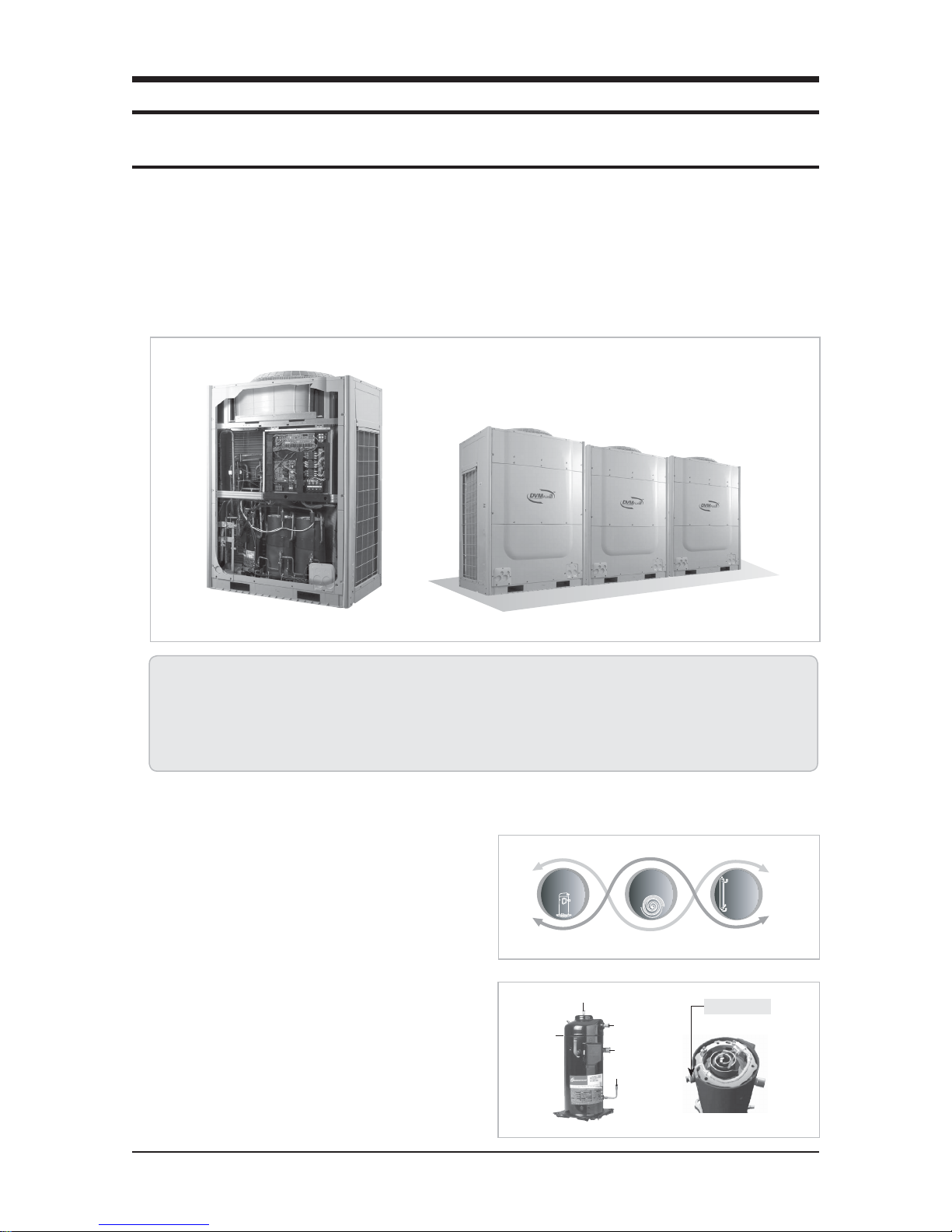
1. Introduction
DVM PLUS III is a module multi-system air conditioner that has the world’s largest capacity(7.5~37.5HP) with the application of a
DVI (Digital Vapor Injection) compressor, and can connect up to a maximum of 49 indoor units.
• The highest COP levels in the industry
• The smallest installation space requirement in the world
• The highest heating capacity and COP in low temperature condition (14°F/-10°C)
• Possible to connect up to 49 indoor units
• Digital unit module
2.
New technology of DVM PLUS III
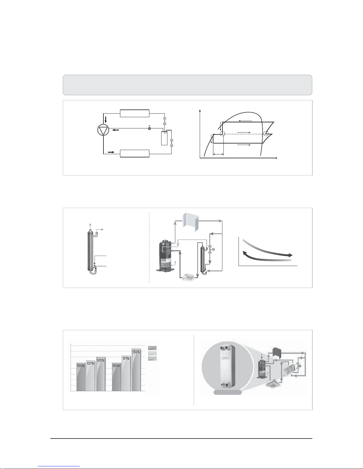
Q Digital hybrid system
DHS (Digital Hybrid System) is a brand new concept system
composed of DVI (Digital Vapor Injection) compressor, vapor
injection technology and turbo intercooler. These 3 factors
together provide highly efficient performance.
1) DVI compressor
Efficient and reliable DVI (Digital Vapor Injection) compressor
coupled with vapor injection technology has been applied to
improve cooling and heating performance and energy efficiency.
Compressor
Vapor
injection
port
DVI
PWM valve
Vapor
Injection
Discharge port
Suction port
Oil port
Turbo
Intercooler
Gas inlet
Samsung Electronics 2-1
Product Specifications
2) Vapor injection technology
Improved cooling and heating performance and COP by a new technology of two stage compression. As injecting optimized
mid-range pressure refrigerant, this technology achieved the high heating performance and COP under the lowest temperature,
which leads the industry.
• Increase refrigerant flow rates with a new vapor injection technology.
• Improved sub-cooling necessary for long piping installation while increasing cooling and heating performance and COP.
More mass flow passing Indoor unit
Evaporator (ID)
DVI compressor
Vapor injection
Condenser (OD)
Mo
Mi
Mo + Mi
Solenoid Valve
2nd
EEV
Flash tank
1st
EEV
1st Expansion
2nd
Expansion
Vapor injection reduces the liquid enthalpy in flash tank,
facilitating heat exchanger to absorb heat more.
increases heating capacity.
Mo + Mi
Mi
Vapor injection
Mo
Enthalpy (kJ/kg)
Injection
point
3) Turbo intercooler (RVXVH075/100/125FE, RD075/100/125VHXFA Only)
Turbo intercooler (Shell & tube type) improves cooling and heating COP and secures reliable operation of installation with long
piping [200m(656ft)].
Subcooling liquid refrigerant
Low temperature gas
refrigerant
Low temp. liquid
refrigerant
Saturated liquid
refrigerant
Temperature
High
Low
4) Plate type intercooler (RD075/100/125VRXFA Only)
The plate type intercooler is the new concept intercooler technology which is more advanced than the existing double layered
pipe type and Shell & Tube type heat exchanger. The plate type intercooler increases heat exchange efficiency by 30% and
provides stable performance with long piping and vertical piping.
Double layered pipe
Shell & Tube
Plate type
Turbo
Inter-
Cooler
DVI
Compressor
EER Heat transfer efficiency
Efficiency Rate
Plate type
Structure Diagram
2-2 Samsung Electronics
Product Specifications
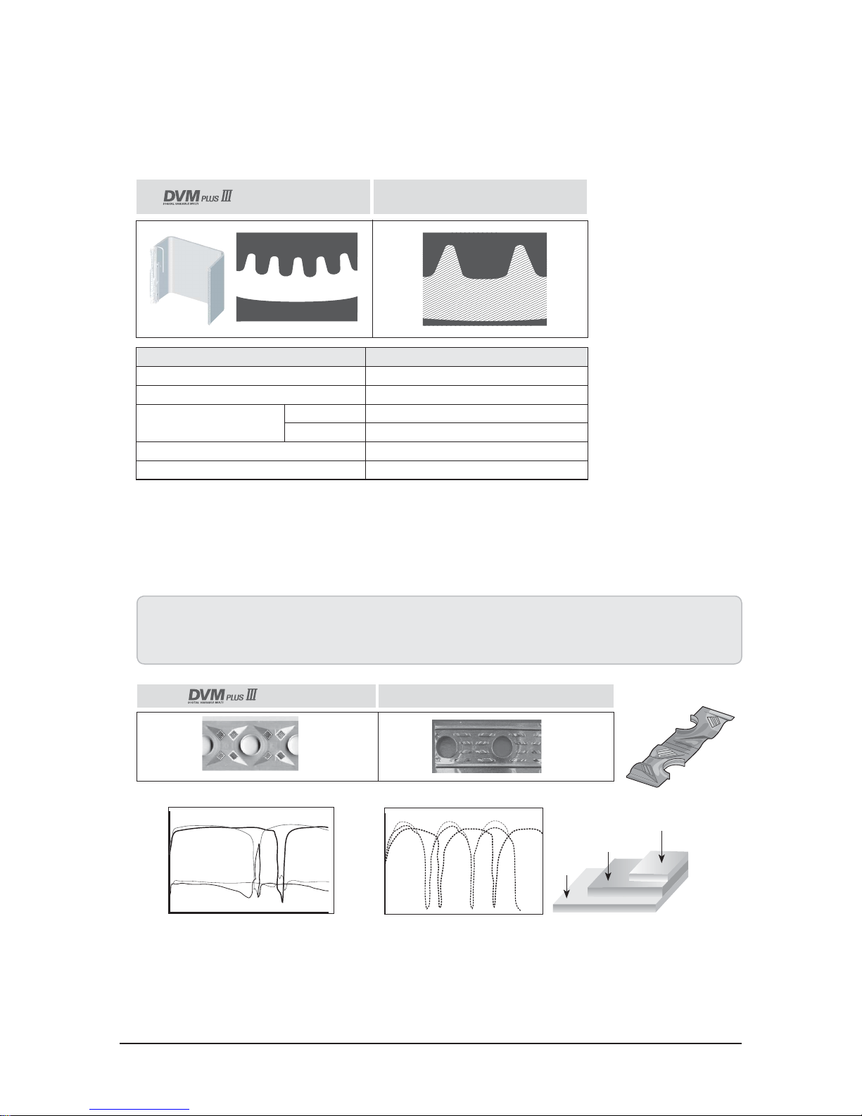
Q High efficiency Ø0.32 heat exchanger
Efficient Ø0.32 grooved tube reduced pressure loss while increasing heat exchange rates to improve COP. Grooved shape is designed
to be high and slim to increase heat transfer performance inside the tube.
New grooved shape
(High and slim)
Company A
Item Improved heat exchanger
Diameter(inch)
Heat transfer surface area
Pressure loss in heat
exchanger
Evaporation
Condensation
Inside heat transfer performance
Ø0.28
14.1%
10.3%
30.8%
o
19%
Ø0.32
n
p
p
n
Pressure resistance same
Q New G-fin
Highly efficient new G-fin increased heat transfer performance, reinforced corrosion resistance, and increased operating duration in
frost condition.
• Heat transfer performance improved by 13% compared to the conventional fin, even with the equivalent pressure loss.
• Epoxy acrylic coating reinforced corrosion resistance.
• 1.4 times longer heating operation in frost condition thanks to new G-fin.
(New G-fin)
60
50
40
30
20
10
0
-10
-20
Eva. Cond., temperature (°C)
-30
030
Time (min.)
5000
4000
3000
2000
1000
Capacity, Power output (W)
60
Conventional model (Louver fin)
0
030
60 90 120
Time (min.)
Anti corrosive layer
Epoxy acrylic
Raw aluminum
material
92μm
Hydrophilic layer
Acrylic resin + surfactant
1.0μm
2.0μm
Samsung Electronics 2-3
Product Specifications
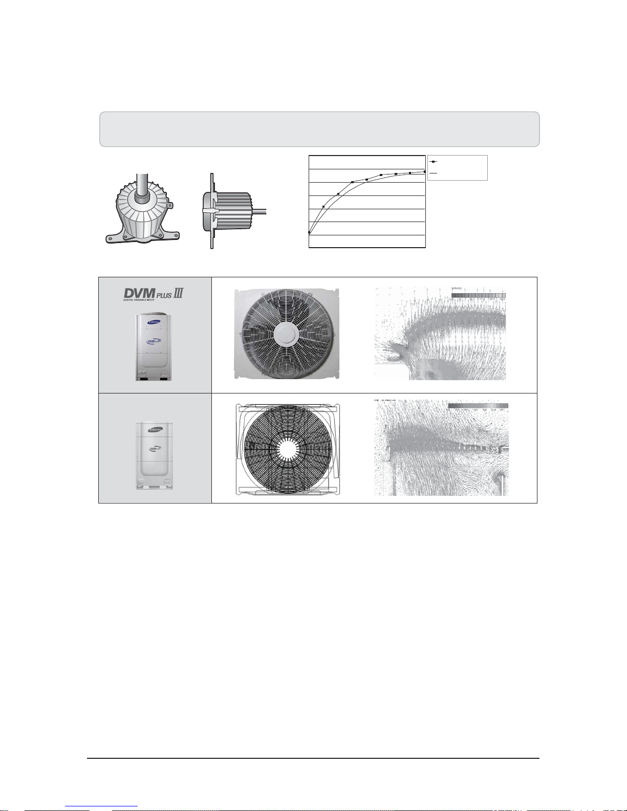
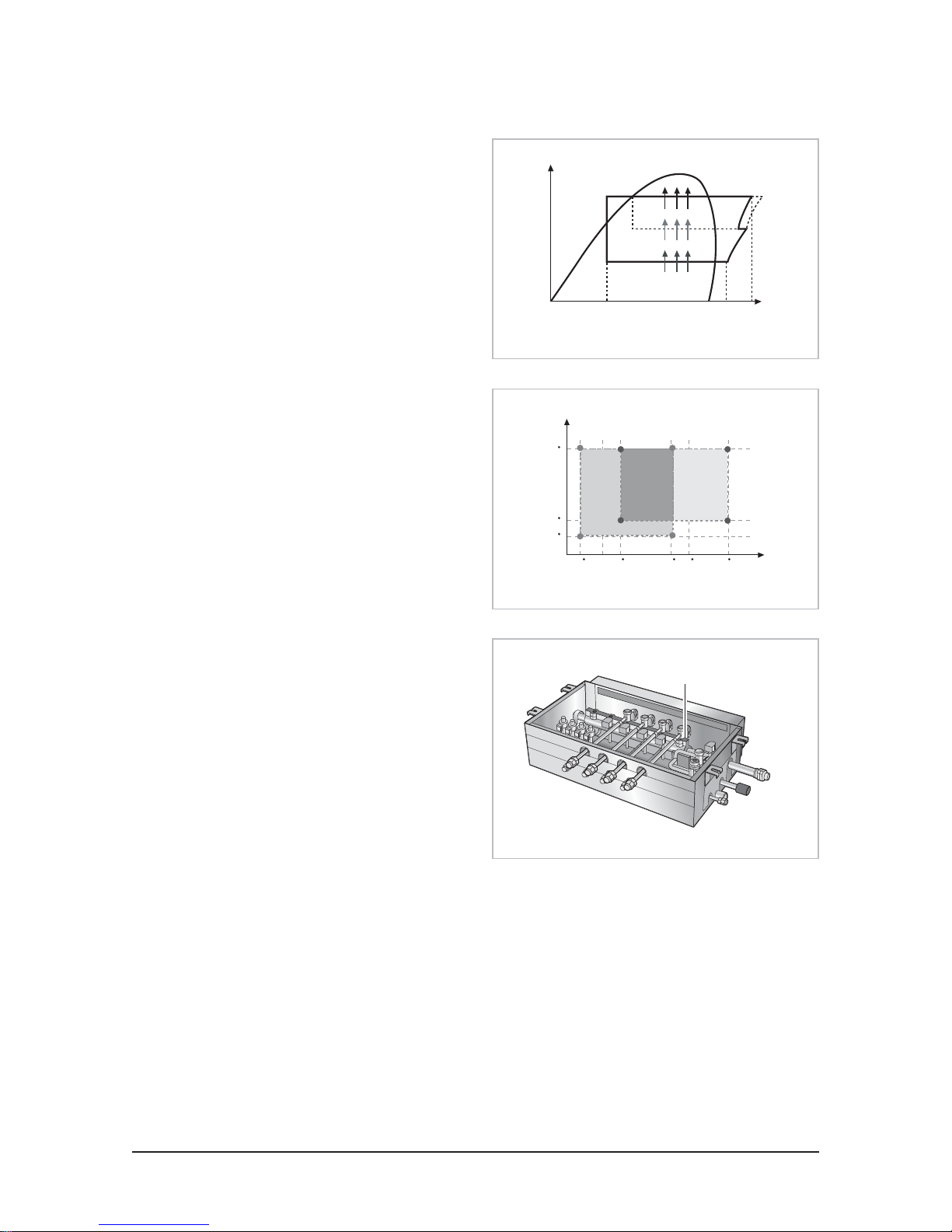
Q Newly designed fan guard
Fan guard has been optimized to improve air volume and reduce noise and vibration.
• BLDC motor, which is 2.7% more efficient than the competitors has been applied.
• High static pressure propeller fan and the optimum Bell mouth figuration for high external static pressure. (8mmAq)
Conventional model
100
90
80
70
60
Efficiency
50
40
30
200 300 400 500 600 700 800 900
RPM
DVM PLUS III
Company A
1000
2-4 Samsung Electronics
Product Specifications
Q Upgraded control solutions
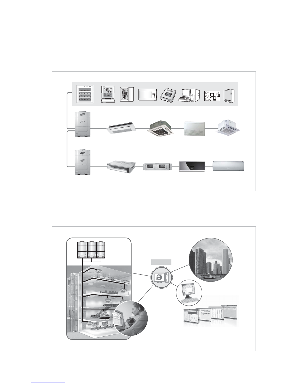
1) Easy management system
A wide range of control system is provided to support various needs and applications such as individual or central control and
automated building management.
2) Enhanced remote analysis
System managers, installers or service engineers can monitor the whole air-conditioning system through the internet, analyzing
the operation and providing service promptly.
Internet
Samsung Electronics 2-5
Product Specifications
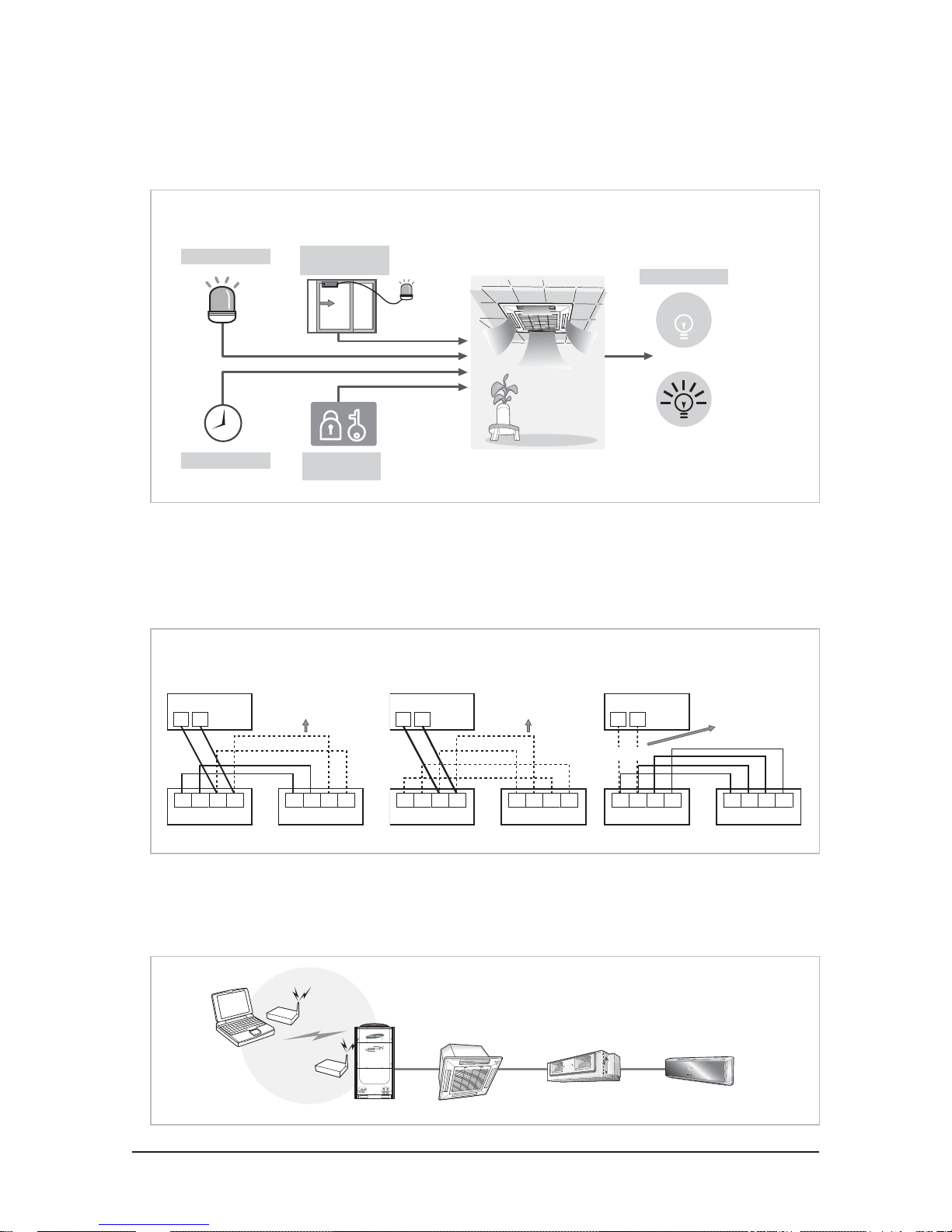
3) Simple contact control
Contact interface makes it possible to connect mechanical contacts to indoor units directly, allowing individual and group control
as well as malfunction monitoring of the indoor units.
Z
Direct ON/OFF indoor unit control
Emergent control
Schedule control
Window
synchronization
Key holder
synchronization
Operation state
Normal
Faulty
4) Wrong wiring protection
Non-polarity communication ensures Normal Operation of air-conditioning system even in case of wrong communication wiring.
Furthermore, power protection mechanism protects indoor units from blowing out under a crossed connection between power and
communication wires, resulting in enhancing system safety and robustness.
Z
Z
Automatic recovery for incorrect
Protection against wrong power line connection
communication wiring
Outdoor unit
F1 F2
L N F1 F2
Indoor unit 1
Non-Polarility
Wrong wiring
Wrong wiring
L N F1 F2
Indoor unit 1
Outdoor unit
F1 F2
L N F1 F2
Indoor unit 1
Wrong wiring
Wrong wiring
Wrong wiring
Wrong wiring
Protection
L N F1 F2
Indoor unit 1
Outdoor unit
F1 F2
Wrong wiring
L N F1 F2
Indoor unit 1
Protection
L N F1 F2
Indoor unit 1
5) Wireless test run tool
Zigbee wireless test run tool provides installers with easy and convenient control and monitoring of the outdoor unit and 49 indoor
units without bothersome wiring.
2-6 Samsung Electronics
Product Specifications
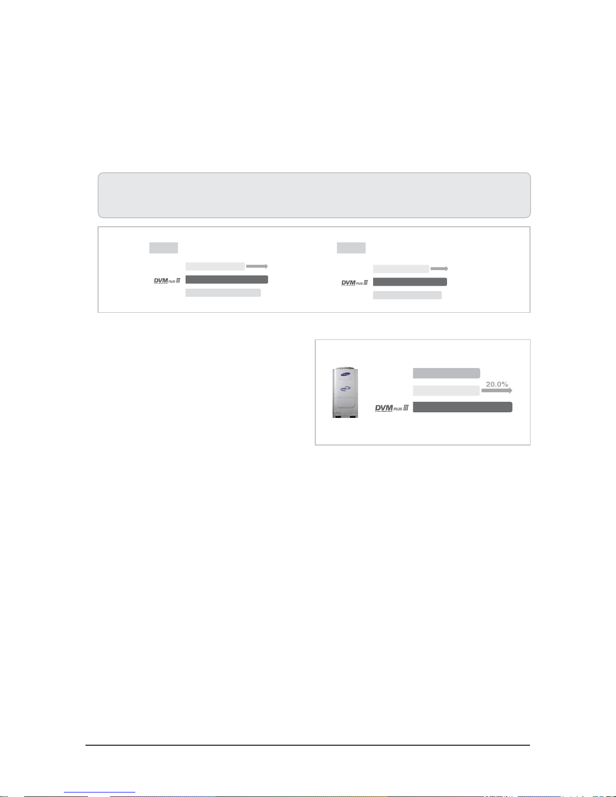
3. Main features of DVM PLUS III, DVM PLUS III HR
T High Performance and Efficiency
Q High COP
High efficiency DVM PLUS III has improved average cooling and heating COP compared to conventional products and achieved the
world’s top class energy efficiency.
• DHS(Digital Hybrid System) technology increased refrigerant flow rate and evaporation enthalpy difference.
• Wide Ø0.32 Grooved tube and new G-fin increased heat exchange efficiency.
• The best BLDC motor in the industry and optimum fan guard design increased efficiency.
17.5HP7.5HP
&RQYHQWLRQDO&RQYHQWLRQDO
&RPSDQ\$&RPSDQ\$
Q Improved heating performance
Vapor injection technology has improved heating performance
by 20% at a low ambient temperature of (14ºF/-10ºC).
&RQYHQWLRQDO&RQYHQWLRQDO
&RPSDQ\$&RPSDQ\$
10HP
Company ACompany A
ConventionalConventional
21kW
21kW
25kW
Samsung Electronics 2-7
Product Specifications
T Simple and Easy Installation
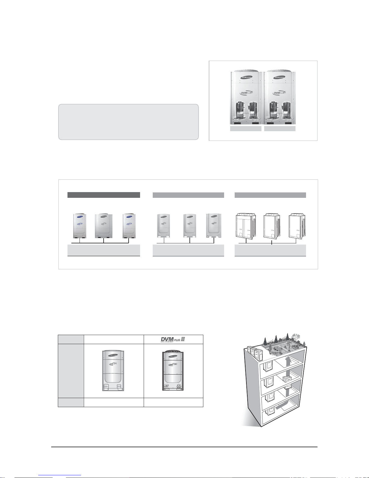
Q Digital unit module
Digital unit module combination enables the system to alternate
compressor operation to prolong each compressor’s life cycle and
improves COP with part loads.
DVI
FVI
Scroll
Scroll
• Control the compressor capacity precisely.
• Ensure long life cycle by alternating operation of the DVI compressors.
• Improve COP using multiple heat exchangers of outdoor units at part
loads.
A unit B unit
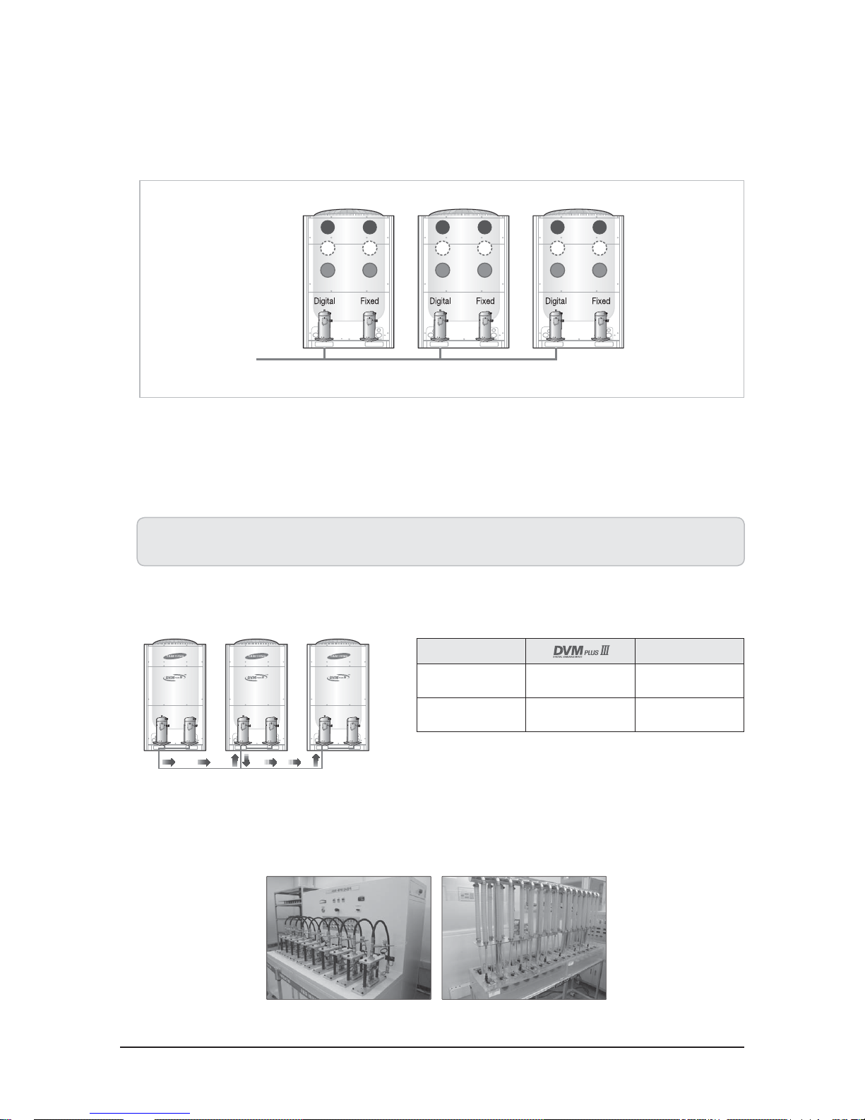
Q Free installation
DVM PLUS III provides the degree of freedom from priority of capacity when installing outdoor units in module.
DVI
Scroll
Scroll
FVI
7.5HP
(Digital unit)
DVM PLUS III
12.5HP
(Digital unit)
Any priority is OK.
10HP
(Digital unit)
Conventional model
7.5HP
(Fixed unit)
A digital outdoor unit with the largest
10HP
(Fixed unit)
capacity should come last.
(Digital unit)
12.5HP
An outdoor unit with the largest capacity
Company A
14HP 10HP
>
should come first.
8HP
>
Q Small size and light weight
To facilitate the convenience and mobility of module installation, DVM PLUS III is the best compact air conditioner in the world
with its small size and weight. It reduces the burden of weight and minimizes the required installation space (it can be installed in
the rooftop), ensuring a more spacious place for relaxation, parking lots, or additional offices, for instance.
Z
Rooftop space (Garden)
Item
Conventional model
Design
Weight
250kg(551lbs) (100%) 240kg(529lbs) (96%)
2-8 Samsung Electronics
Product Specifications
Q Rapid installation
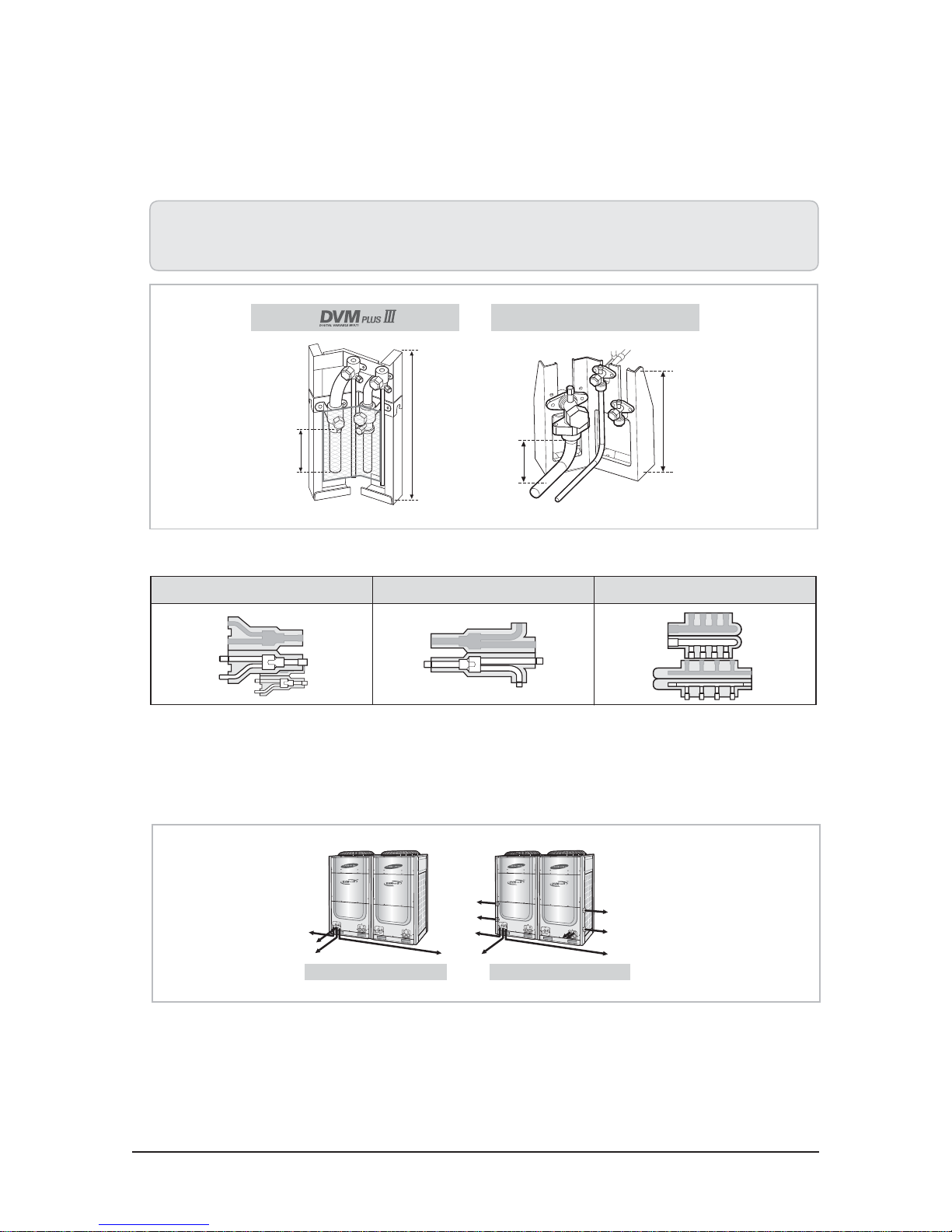
DVM PLUS III supports more convenient and rapid installation work through the improvement of service valve structure and the
provision of branch joints.
• Improved the location of service valve and welding points for aiding piping connection work
• Modified the plate into open structure type for keeping interference out during welding work
• The application of OTS (One Touch Solution) valve that makes it easy to connect pipes and to open or shut valves.
DVM PLUS Ⅱ
423mm(16.65inch)
120mm(4.72inch)
50mm(1.97inch)
260mm(10.24inch)
Ô Y, Header, Outdoor joints allow easy piping expansion and reduction with insulations to facilitate the installation.
Y-joint Outdoor joint Header joint
Q Free piping & wiring directions
DVM PLUS III is easy to install as its piping can be connected from front, right, left and bottom side.
Wiring hole (Conduits) adds convenience as it allows power and communication lines to be connected in various ways and directions.
Samsung Electronics 2-9
Free piping connection Free wiring connection
Product Specifications
Q The world’s longest piping length
DVM PLUS III has an actual piping length of 656ft, with the maximum
piping length of 147.6ft from the first branch joint to the farthest
indoor unit, thereby providing convenience and flexibility for installation for commercial buildings.
Level differences
between indoor &
outdoor unit : 164ft
• The longest piping length : 721.8ft (Equivalent)
• Total piping length: 3280.8ft
• From the first branch joint to the farthest indoor unit : 295.3ft
- Upsize all pipes between branch joints. (liquid&gas)
Level difference between
indoor units : 49.2ft
Q Automatic piping length recognition
With automatic piping length recognition, installation can be carried out without extra PCB setup.
P
The longest pipe length
: 721.8ft (Equivalent)
The first branch
joint to the farthest
indoor unit : 147.6ft
(1 size up : 295.3ft)
∆P
pressure according to
pressure drop of piping
(
∆P
Q High external static pressure
To respond to a range of various installation environments, DVM PLUS
III is designed to be used even in external static pressure of 8 mmAq.
∆P{
Corrected target
compensation)
h
Indoor’s low pressure
(Eva. inlet temperature
of indoor units)
Outdoor unit’s
low pressure
2-10 Samsung Electronics
Product Specifications
T Easy Maintenance
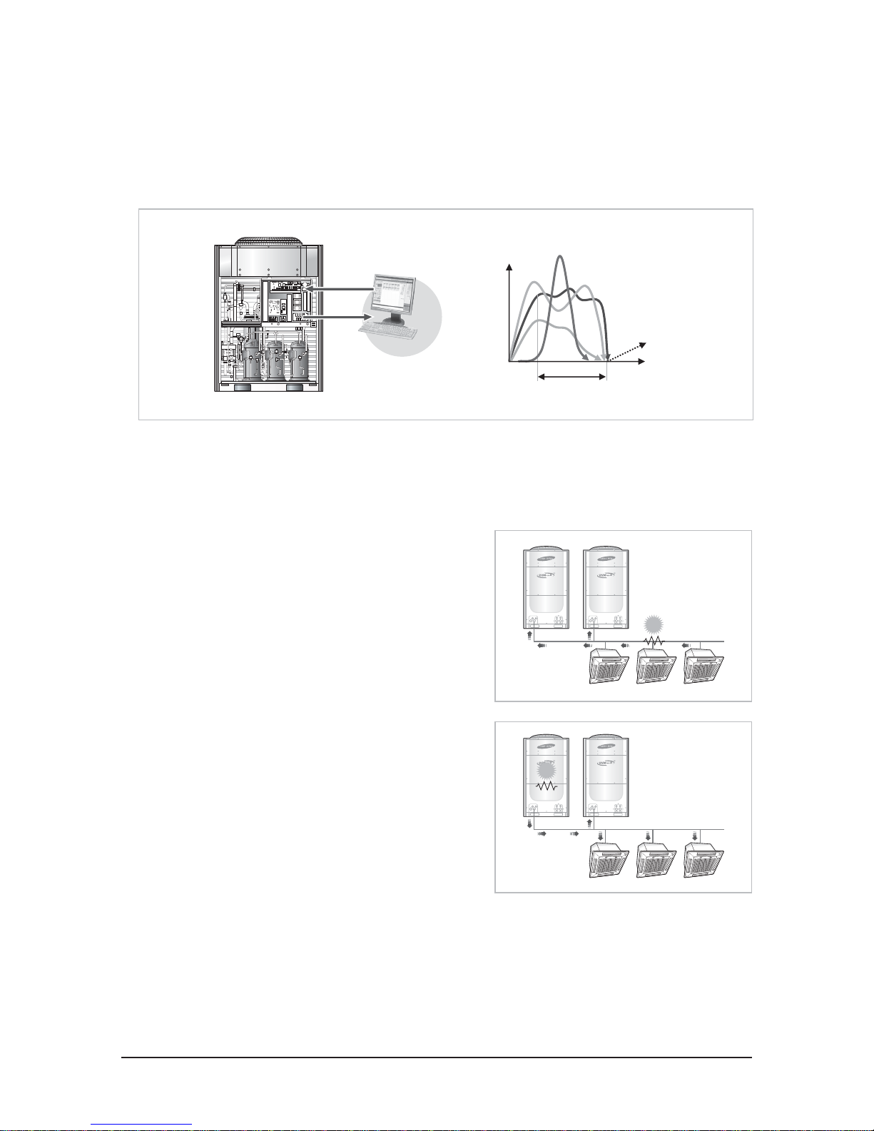
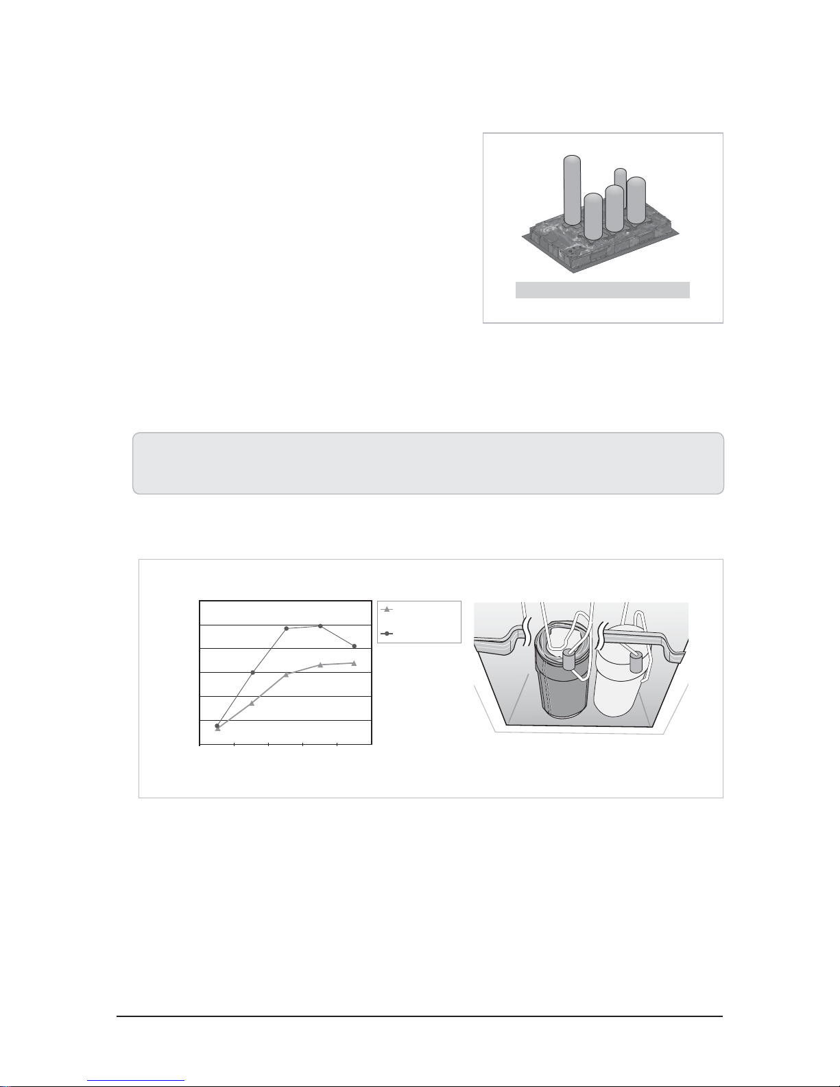
Q Auto data backup in PCB
In case of problems in product, operation information of last 20 mins is stored before system shut down. Therefore, DVM PLUS III can
be diagnosed rapidly and serviced.
High pressure
Data
SNET 1+
Data storing
Q Refrigerant pump-down and pump-out
DVM PLUS III provides several functions to facilitate the replacements of product, additional installation and maintenance without
much effort.
Fan motor RPM
Current
System
stop
Time
Z
Refrigerant pump-down function
In case of moving outdoor units, maintenance of pipes between
indoor units, between outdoor units and indoor units, it is possible
that recover refrigerant into outdoor units.
Z
Refrigerant pump-out function
In case of maintenance of outdoor units, it is possible that recover
refrigerant into indoor or pipes.
Breakdown
Breakdown
Samsung Electronics 2-11
Product Specifications
T High Reliability
Q Optimum control and high reliability of DVI scroll compressor
1) DVI scroll compressor
As DVM PLUS III employs a DVI scroll compressor, it can adjust not only the compressor capacity linearly in accordance with
indoor loads, but at minimum load. Therefore it is superior to Inverter system in creating a pleasant indoor environment and
energy saving.
DVI
DVI
compressor
DVI
compressor
compressor
FVI
compressor
Inverter
compressor
Company A
2) Dual compliances
Through rigorous tests such as High load and liquid
flood back, DVI compressor is evaluated as reliable as it
can operate under any conditions.
°F
°C
170
Condensing temperature
°F
°C
Evaporating temperature
As DVI compressor is mechanically simple in structure, it has strong durability, and flexibility in radial and axial directions while being
strong against debris, liquid flood back, leakage of refrigerant inside the scroll, and internal overheating. In particular, it is very strong
against partial abrasion and compressor burn out by internal overheating compared with inverter compressor that employs tip seal
techniques.
Z
Radial compliance
Z
Axial compliance
Floating seal
Debris
2-12 Samsung Electronics
Lower scroll
(Orbiting)
Upper scroll
(Fixed)
Product Specifications
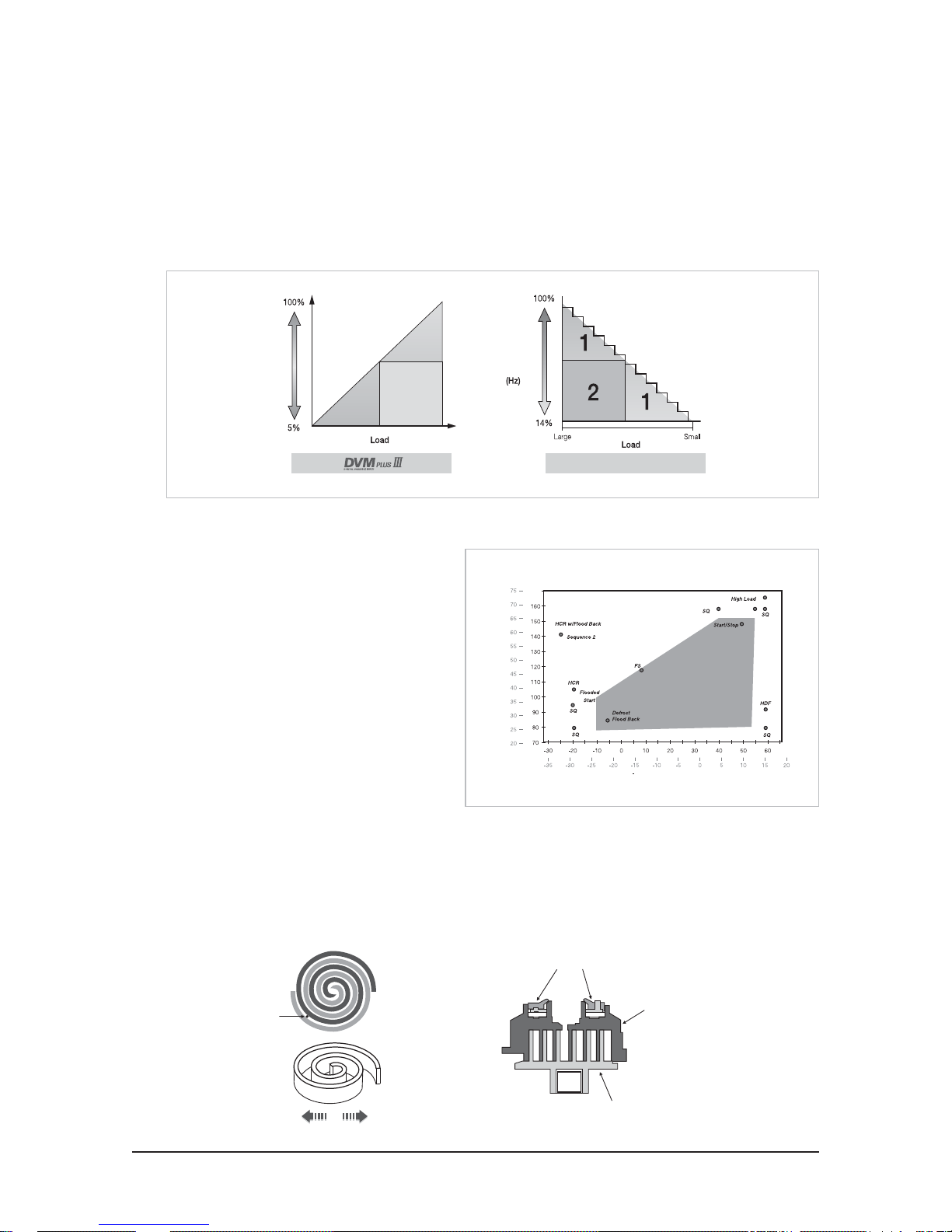
Q Compressor operating pattern
Digital unit’s module installation secures reliability of long life cycle with sequential activation of compressors and improves part load
efficiency as it is possible to use bigger outdoor units to take care of part load.
Q Oil balancing and recovery technology
In terms of oil recovery that is the most important operation in module system air conditioner’s reliability,
DVM PLUS III :
• Achieves continuous cooling or heating during oil recovery operation.
• Allows level difference between outdoor unit module.
Ô DVM PLUS III’s oil recovery has much higher reliability as internal and external oil balancing take place simultaneously.
Z
Oil balancing
Z
Oil recovery
Company A
Oil recovery during
cooling operation
Oil recovery during
heating operation
Cooling operation Cooling operation
Heating operation Cooling operation
Q Acceleration life cycle test
All parts fitted to DVM PLUS III ensure reliability for life cycle through ALT (Acceleration Life cycle Test ).
Samsung Electronics 2-13
Product Specifications
Q Robust design
DVM PLUS III ensures product reliability through robust design against all
potential defects that can occur in the process of production, distribution
and customers’ usage environment.
Robust design through CAE
T Sound Quality
Q Sound quality
DVM PLUS III improves the problem of noise not only at the low sound level, but also at the actual sound quality level by:
• Developing a sound insulation material for compressor
• Improving fan guard air flow
• Adopting Ø0.32 heat exchanger
Ô In particular, it enhances sound quality as it improves compressor noise by 4dB(A) by employing new material with better
acoustic absorptivity.
1.200
1.000
0.800
0.600
0.400
Acoustic absorptivity
0.200
0.000
250 500 1000 2000 4000
Frequency (Hz)
Conventional
material
New material
2-14 Samsung Electronics
T Environment Friendly
Q Small refrigerant charge amount
With consideration of environment, DVM PLUS III is less charged compared to competitor’s products.
of (10HP) Company A (10HP)
Refrigerant volume 7.5kg(16.5lbs) 8.4kg(18.5lbs)
% 89 100
Q Refrigerant leakage prevention
To prevent refrigerant leakage, we provide how to diagnose any refrigerant leakage in operation. Also,
changing service valves from flange type to brazed type further prevents refrigerant leakage.
Product Specifications
Q RoHS compliance
RoHS restriction only applies to small or large household appliances, IT equipment, lightings, power train, toys, leisure or sports
equipment, and vending machines.
Samsung expands the RoHS restriction into its entire range of products based on its own environmental policies.
Q Lead-free
DVM PLUS III is an environment friendly product that prevents pollution problems caused by the use of lead, by applying lead-free
indoor and outdoor PCBs.
Samsung Electronics 2-15
Product Specifications
4. DVM PLUS III HR
1) Versatile application
As DVM PLUS III HR allows a simultaneous cooling and heating operation with one system, the product makes it possible for a wide
range of applications.
• Great for places where simultaneous cooling and heating operation is required such as hotels, nursing homes, conference rooms,
etc.
• For seasonal air-conditioning which may need a simultaneous cooling and heating operation.
• In case of medium or large office, DVM PLUS III HR satisfies cooling and heating operation simultaneously for the requirements of
interior and perimeter zone.
Z
Simultaneously cooling and heating for individual rooms
Heating
Cooling
Heating
Z
Simultaneously cooling and heating for each zone
Perimeter Zone : Heating Interior Zone : Cooling
MCU (Mode Change Unit)
Cooling
Cooling
Heating
2-16 Samsung Electronics
DVM PLUS III HR
2) High COP
P
As DVM PLUS III HR utilizes the retrieved energy from indoor
cooling operation for heating, which has a high energy
efficiency and is further enhanced by our Vapor Injection
technology.
3) Wide operation range
DVM PLUS III HR can carry out a simultaneous cooling and
heating operation within a wide range of temperatures.
h
3
Indoor
temp.
30 C
Simultaneous
operation
zone
18 C
16 C
Heating
-20 C -10 C 24 C 30 C 43 C
Product Specifications
Q3
Q2
Q1
h2h
1
h
Cooling
Outdoor
temp.
4) New MCU
The MCU for DVM PLUS III HR has a double-tube heat
exchanger for securing high subcooling effect by the MCU
itself, thus improving the reliability of the long piping and
cooling and heating performance.
MCU subcooling heat exchanger
Samsung Electronics 2-17
Product Specifications
Feature(Cont.)
2-1-1-2 RD040/050MHXCA
Summarize
Overview
POWER SAVING
Samsung patented compressor
Samsung has been researching and developing compressors since the 70's.
It has developed power saving compressors for more than thirty years.
The SUPER FJM compressor adopts a double-rotor BLDC compressor with permanent magnets made by Samsung. Electricity for the
compressor rotor is obtained from a neodium-iron-boron permanent magnetic material (boron magnet can attract iron material weighing
1000 times its own weight.) It strengthens the rotary moment of the compressor to maximize the entire efficiency of the compressor.
SUPER FJM is an all-in-one type product integrating the control R&D and Samsung patented compressor.
The air conditioning system uses the latest single tube in parallel connection and both the indoor and
outdoor machines use independent electronic expansion valves to control the amount of coolant.
You can connect a maximum of nine indoor machines to one outdoor machine.
SUPER FJM considers the trend in air conditioner use. It optimizes the energy efficiency
of loads ranging from partial to full. It achieves an excellent energy effect for the users
of the air conditioner.
BLDC electricity
“Permanent magnet,” strong magnetic rotor
Double rotor compression cylinder
Nd-Fe-B Neodium-Iron-Boron magnet
SAMSUNG's double-rotor compressor has the upper and lower rotors designed symmetrically.
The double rotor in symmetry can remove vibrations caused by the eccentric design of the cylinder.
2 rotors balancing the rotary moment
Permanent magnet rotor
Eccentric design
Nd-Fe-B Neodium-Iron-Boron magnet
Centered symmetry
Upper cylinder
Lower rotor
Upper rotor
Lower cylinder
High efficiency heat exchanger
SUPER FJM uses new multiple-teeth screw pipes with a diameter of 8 mm to improve the heat exchangeability of the pipe by 30.8%.
The water-friendly aluminum foil in the heat exchanger uses the G-fin patent design to improve the efficiency of heat exchange by 13%.
Multiple-teeth screw pipes
General screw pipes
DC fan electricity
The SUPER FJM outdoor machine uses DC fan electricity. The rotational speed of electricity is 100 RPM to 1050 RPM with step-free control.
The electrical efficiency is improved by about
33% compared to AC electricity.
2-18 Samsung Electronics
Efficiency
Speed (RPM)
Product Specifications
Excellent energy efficiency
All the SUPER FJM series is superior to class 1 energy efficiency, the power saving standard for multiple connection (heat pump) machines.
Its IPLV(C), the comprehensive energy efficiency is 4.94.
Lower energy consumption
Middle
Higher energy consumption
FRESHNESS AND HEALTH
Environment friendliness
SUPER FJM uses the environment-friendly coolant, R410A and all of its parts are in strict compliance with the EU environment guidelines (RoHS).
It controls toxic materials and prevents damage to the atmosphere. It does not spread any toxic materials indoors.
Strong heater
SUPER FJM adopts Samsung's high performance double-rotor compressor. Compared to other products, its heating effect at -10°C is about 20% higher.
à SUPER FJM's excellent energy efficiency
World's number one class
Energy efficiency
SUPER FJM
Comprehensive energy efficiency
SUPER FJM optimizes the aspects of environment friendliness, air control, toxic
material control, low temperature heaters and noise. It guarantees a refreshing
and healthy environment for the user.
Cadmium
Lead
Brominated flame retardant
Poly brom penyl
With smart
control
Hexa chromium
mercury
Heating performance (kW)
Heating performance
improved 20%
External temperature(°C)
SUPER FJM measurement
Other product measurement
Other product measurement
Outside temperature rises about 7°C
Inside temperature rises about 3°C
The air conditioning capacity increases about 0.8HP
Deep level anti-bacteria
All of the SUPER FJM indoor heat exchanger aluminum foil is processed with special anti-bacteria paint to prevent the growth of bacteria
in the humid inner area of the air conditioner and maintain clean indoor air.
Basic materials for the aluminum foil
Anti-corrosion layer
(resin, anti-corrosion materials)
Water friendly layer
(Silicon+water-friendly material
+anti-corrosions)
Indoor machine heat exchanger
Aluminum foil pin
Ticks in the blankets
Sofa ticks
Carpet ticks
Pet's ticks
Threatens the indoor air environment.
Samsung Electronics 2-19
Product Specifications
Quiet operation of the indoor machine
SUPER FJM's indoor machine has a minimum noise level of 21 decibels. Even in the late, quiet night, you can hardly hear any noise.
Quiet night
SUPER FJM's outdoor machine can be set to quiet nighttime operation mode. The outdoor machine executes quiet operation (sleeping mode)
after six hours. After 12 hours, it returns to the previous mode automatically.
Hearing test room Library room Office room Convention hall Crowded streets
Environment load
change curves
Max temperature
Temperature change curve
Decibels
Noise change curve
(sleeping mode)
SIMPLE DESIGN AND INSTALLATION
Long pipe
The SUPER FJM indoor/outdoor machine's pipe length is a max. of 70 meters. The max. drop height between the indoor and the outdoor
machines is 30 meters. (If the outdoor machine is located below the indoor machine, it is 25 meters). The max. pipe length after installation of the
first branch pipe is 40 meters.
After 6 hours
1 hour of quiet operation
Start Stop
The SUPER FJM design supports simple installation. The outdoor and indoor
machines use a copper pipe and a branch pipe string in parallel connection.
They are provided with electricity independently.
Bedroom
Bedroom
Max outdoor/indoor drop heights 30m
Max actual pipe length 70m
Max drop heights between the indoor machines 15m
(Caution: The max. pipe length for the 3HP model is 45 meters.
The max. indoor/outdoor drop height is 15 meters and the max. drop heights
between the indoor machines is 7.5 meters.
The max. pipe length after installation of the first branch pipe is 30 meters.)
Bedroom
Kitchen
Livingroom
Bedroom
Limitations of the operational current classes
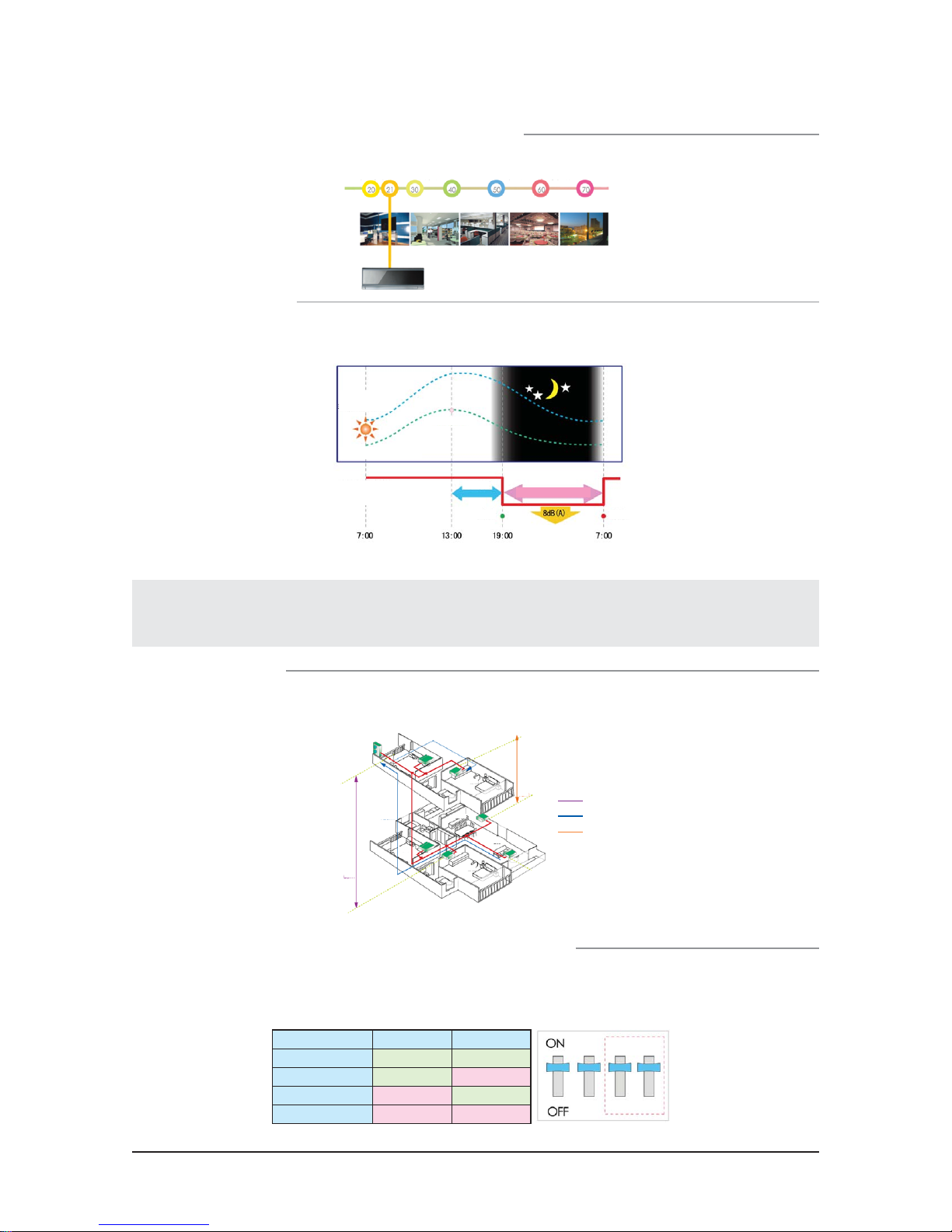
SUPER FJM's indoor/outdoor machine control circuit board uses four types of current limits mode. It can be efficiently installed in an area with
a shortage of electrical stability. If it is to be remodeled for an old building that does not meet the electricity capacity standard, first install an air
conditioner for testing. Then set the current after expanding the electricity capacity.
Current limit mode DIP button DIP button
Mode 1 ON ON
Mode 2 ON OFF
Mode 3 OFF ON
Mode 4 OFF OFF
2-20 Samsung Electronics
Product Specifications
PROHIBITION
Independent smart central control
Independent controllers are installed in each indoor machine of SUPER FJM. Using the central controller, it can control all the indoor machines at
home. When leaving home, use the central controller installed in the living room to turn off all the air conditioners. You can prevent unnecessary
power consumption caused by the air conditioner running with no one at home.
Smart group control for multiple households
SUPER FJM supports group controls in conjunction with Samsung's other commercial air conditioners. It achieves a wide range of smart control
including individual metering for each household, computer monitoring and network monitoring.
Ethernet
SUPER FJM with smart control uses the smart network control method for management and
support simple controls.
ON/OFF central controller
Bedroom
Kitchen
Livingroom
Bedroom
Connection
Functional central controller
SPEEDY TROUBLESHOOTING
that support speedy troubleshooting.
Self diagnosis of malfunctions
SUPER FJM is designed to perform perfect smart self diagnosis functions
The SUPER FJM indoor/outdoor machines has an LED monitor where you can quickly diagnose the operational variables and repair them
Control parts Malfunction codes
LED display of the control panel
of the outdoor machine
Codes Causes for malfunction
Communication failures between the indoor
E101
machine and the outdoor machine
Bad power connection between the indoor and
E460
the outdoor machines
E467 Bad operation of the compressor
E466 Inadequate voltage supply
Auto recovery of the coolant
SUPER FJM is designed to support the saving function that recovers the coolant automatically for the user. Depending on which outdoor or
indoor machine is being repaired, it decides which machine to recover the coolant from. This way, the amount of coolant can be saved.
Repaired indoor machine Repaired outdoor machine
Samsung Electronics 2-21
 Loading...