

Samsung RD060PHXEA, RD070PHXEA, RD080PHXEA, RD110PHXEA, RD140PHXEA Installation Manual
...
INSTALLATION
MANUAL
Outdoor Unit
RD060PHXEA
RD070PHXEA
RD080PHXEA
RD110PHXEA
RD140PHXEA
RD160PHXEA
DB98-00000A(1)SE F I DP
Air to Water Heat pump
ESPAÑOLFRANÇAISITALIANOPORTUGUÊSDEUTSCH ENGLISH

E-2
Contents
SAFETY PRECAUTIONS
. . . . . . . . . . . . . . . . . . . . . . . . . . . . . . . . . . . . . . . . . . . . . . . . . . . . . . . . . . . . . . . . . . . . . . . .
3
PRODUCT SPECIFICATION
. . . . . . . . . . . . . . . . . . . . . . . . . . . . . . . . . . . . . . . . . . . . . . . . . . . . . . . . . . . . . . . . . . . . . .
6
LOCATING THE UNITS
. . . . . . . . . . . . . . . . . . . . . . . . . . . . . . . . . . . . . . . . . . . . . . . . . . . . . . . . . . . . . . . . . . . . . . . . .
8
INSTALLING THE REFRIGERANT PIPE WORK
. . . . . . . . . . . . . . . . . . . . . . . . . . . . . . . . . . . . . . . . . . . . . . . . . . .
16
ELECTRICAL CONNECTIONS
. . . . . . . . . . . . . . . . . . . . . . . . . . . . . . . . . . . . . . . . . . . . . . . . . . . . . . . . . . . . . . . . . .
28
SETTING THE OPTION SWITCH AND FUNCTION OF THE KEYS
. . . . . . . . . . . . . . . . . . . . . . . . . . . . . . . . . . .
35
PUMP DOWN PROCEDURE
. . . . . . . . . . . . . . . . . . . . . . . . . . . . . . . . . . . . . . . . . . . . . . . . . . . . . . . . . . . . . . . . . .
38
COMPLETING THE INSTALLATION
. . . . . . . . . . . . . . . . . . . . . . . . . . . . . . . . . . . . . . . . . . . . . . . . . . . . . . . . . . . . .
41
FINAL CHECKS AND TRIAL OPERATION
. . . . . . . . . . . . . . . . . . . . . . . . . . . . . . . . . . . . . . . . . . . . . . . . . . . . . . .
42
TROUBLESHOOTING
. . . . . . . . . . . . . . . . . . . . . . . . . . . . . . . . . . . . . . . . . . . . . . . . . . . . . . . . . . . . . . . . . . . . . . . . .
43
E-3
ENGLISH
Safety Precautions
R410A refrigerant is used for Air to Water Heat pump.
-
When using R410A, moisture or foreign substances may affect to the capacity and reliability of the
product. Safety precautions must be taken when installing the refrigerant pipe.
- The design pressure of the unit is 4.1MPa (41.8 kgf/cm²).
Select appropriate material and thickness according to the regulations.
- R410A is a quasi-azeotrope of two refrigerants.
Make sure to charge liquid one when adding refrigerant.
If you charge gaseous refrigerant, it may affect the capacity and reliability of the
product as a result of change formation of the refrigerant.
Connect only the indoor units fit on R410A refrigerant. Check whether the indoor units
can be connected with the product’s catalogue.
(When incorrect indoor units are connected, they cannot operate normally.)
When installing, use tools and materials for R410A only. If you use tools and materials for R22,
there is potential risk of bursting, injury, electric shock and fire because the pressure
of R410A is higher than the pressure of R22(conventional).
You must install the product by qualified installer. If you install the product on your own or by unqualified
person, Samsung is not responsible for any damages which may occur due to incorrect installation.
Make sure to read the following safety precautions carefully before installation.
Make sure to observe the cautions specified in this manual.
Conduct a test run of the unit after installation and then explain all system functions to the owner.
Follow IEC (International Electrotechnical Commission) standards for the power input and
ISO (International Standards Organization) standards for input current.
WARNING
Hazards or unsafe practices that may result in severe personal
injury or death.
Installation must be carried out by a qualified installer. Do not attempt to repair, move, modify or
reinstall the unit on your own since such act may cause fire, electric shock or water leakage.
Install the unit in a place where it is strong enough to hold the product weight. When installed in place
where it is not strong enough to withhold the product weight, the unit could fall and cause injury.
The unit should be installed in accordance with the National Electrical regulations. Check if the
voltage and the frequency of the main power supply are those required for the unit to be installed
and check the connection. Do not share the power outlet with other appliances. Incomplete
connection, defective insulation or exceeding the permissible current may cause electric shock or fire.
Use the specified wires to connect the indoor and outdoor units securely and attach the wires
firmly to the terminal block connecting sections so that the pressure is not applied to the sections.
Inappropriate connection and fixing could cause fire.
WARNING
Hazards or unsafe practices that may result in severe personal injury or death.
CAUTION
Hazards or unsafe practices that may result in minor personal injury or property damage.

E-4
Attach the electrical cover to the indoor and outdoor unit securely without any gaps. If there are
any gaps, there is potential risk of fire or electric shock due to dust or water.
Make sure to use the part provided or specified parts for the installation work. The use of defective
parts could cause an injury or leakage of water due to a fire, an electric shock, the unit falling, etc.
Make sure that the refrigerant gas does not leak after completing the installation. If the refrigerant
gas of the indoor unit leaks and comes into contact with the fan heater, space heater or stove,
harmful gas will be generated.
Ensure that the national safety code requirements have been followed for the main supply circuit.
Ensure that a proper ground wire is in place. Do not connect the ground to a gas pipe, water pipe,
lightning rod or telephone grounding. Defective grounding could cause electric shock.
Do not install the unit in a place with direct sunlight, dangerous substances or where it is exposed
to inflammable gas leakage to prevent explosion, fire or personal injury.
Perform the installation securely referring to the installation manual. Incomplete installation could
cause personal injury due to fire, electric shock and water leakage or from the unit falling.
Check first the following situations before starting the operation during the installation.
- The pipe must be properly connected and make sure there is no leakage.
- Service valves must be open. If compressor is operated with the service valve closed, excessive
pressure may damage parts of the compressor.
If leakage occurs on any of the connection, air inflow may also cause excessive pressure that could
lead to explosion.
Stop the compressor before disconnecting the refrigerant pipe for pump-down operation. If you
disconnect the refrigerant pipe while compressor is operating with service valve open, air inflow will
cause excessive pressure in the refrigerant cycle that could lead to explosion and personal injury.
Do not assemble the power cord on your own, use two cables together to extend the cable length
or tangle the cable. Bad connection, isolation and over voltage may cause fire or electric shock.
Make sure to turn off the main power when setting up the indoor unit electrical circuit or power
cords. There is a risk of electric shock.
Make sure that proper circuit breaker and safety switches are installed. Install a ground leakage
breaker depending on the installation place (where it is humid). If not, it may cause electric shock.
Do not install the unit by yourself (owners). Incorrect installation of the unit could cause injury due to
fire, electric shock and water leakage or from the unit falling. Consult a dealer or a qualified installer.
Use the unit on a single outlet circuit. Do not share the power outlet with other appliances. Obtain
the consent by a qualified installer before connecting the unit to the power supply system. An all
pole disconnection from the power supply must be incorporated in the fixed wiring with a contact
opening of >3mm.
Manufacturer is not responsible for accidents due to incorrect installation.
When you install the Air to water heat pump in a small room, you consider a proper ventilation to
prevent a leakage level within the maximum permissible limit.
- In that case, you may die from suffocation by some possibility.
Fix the outdoor unit securely to prepare against strong wind or earthquake.
- If the outdoor unit is not properly fixed, it turns over and accidents may occur.
If any gas or impurities except R410A refrigerant come into the refrigerant pipe, serious problem
may occur and it may cause injury.
Install the cables with supplied cables firmly. Fix them securely so that external force is not exerted
to the terminal board.
- If the connection or fixing is incomplete, it can cause trouble with a heat generation, electric
shock or fire and so on.
Safety Precautions
(Continued)

E-5
ENGLISH
CAUTION
Hazards or unsafe practices that may result in minor personal injury or
property damage.
Perform the drainage/piping work securely according to the installation manual. If not, water could
drop from the unit and household goods could get wet and damaged.
Fasten a flare nut with a torque wrench as specified in this installation manual. When fastened too
tight, a flare nut may break after a long period of time and cause refrigerant leakage.
Wear thick gloves during the installation process. If not, personal injury may occur due to the
Air to water heat pump parts.
Be careful not to touch the outdoor unit inlet or aluminum pins. You may get personal injury.
Do not install the outdoor unit in a place where animals could live. If an animal get contact with
the electric parts, damage or fire may occur. In addition ask the customer to maintain a clean
installation place around it.
After completing the installation run the trial operation. If no error occurs, explain to the customer
how to use and clean the Air to water heat pump according to the user’s manual. In addition give
the installation manual and the user’s manual to the customer.
Check the unit for damage that may have taken place during transportation and do not install or
use damaged equipment.
All of the manufacturing and packaging material used for your new appliance are compatible with
the environment and can be recycled.
Dispose of the packaging material in accordance with the local requirements.
This product is an air conditioning system and contains a coolant that must be recovered and
disposed of in an appropriate way by qualified personnel. At the end of the life cycle, take it to a
proper recycling or disposal center or return it to the dealer so that it can be disposed correctly.
Do not connect the heater to the outdoor unit and do not install remodeled duct as you please.
- The capacity of the Air to water heat pump may reduce, electric shock or fire may occur and it
has a chance of occurrence of and accident like electric shock or fire.
Make sure that the condensed water dripping from the drain hose runs out properly and insulate
the drain pipe so that frost does not generate.
- Household goods may get wet if the drain pipe is not properly installed.
Install the power cable and communication cable of the indoor and outdoor unit at least 1.5m
away from electric appliances.
- Noise may hear depending on the electric wave though the cables are installed away from
electric appliances.
Install the indoor unit away from lighting apparatus using the ballast.
- If you use the wireless Remote controller, it may not operate normally.
E-6
Product Specification
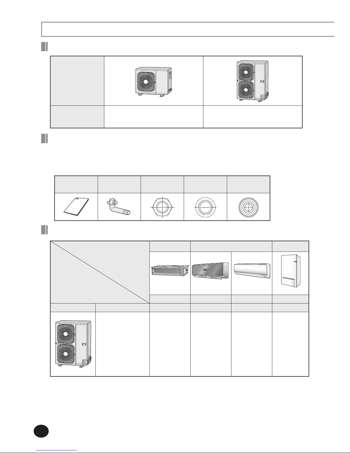
Shape of the outdoor unit
Shape
Model Name
RD060PHXEA
RD070PHXEA
RD080PHXEA
RD110PHXEA
RD140PHXEA
RD160PHXEA
Keep supplied accessories until the installation is finished.
Hand the installation manual over to the customer after finishing installation.
The quantities are indicated in parentheses.
Accessories
Installation
manual (1)
Drain plug (2) Fastener-nut(1)
Rubber-cover
wire(2)
Drain cap (1)
Product compatibility
Duct Line RAC Line A2W Line
Slim Duct Vivace Neo-Forte Hydro Unit
2.2~5.6kW 2.2~7.1kW 2.2~7.1kW
8/16kW
Classification
Features
Slim Duct Premium RAC RAC Hydro Unit
- Heat pump for
heating and hot water
system [ Eco Heating
Full System]
- Outdoor unit :
6/7/8/11/14/16 kW
-
Long pipe reliability : 75m
- Eurovent LCP, NF
PAC registration
NH022LHXEA
NH028LHXEA
NH036LHXEA
NH045LHXEA
NH056LHXEA
NH022VHXEA
NH028VHXEA
NH036VHXEA
NH056VHXEA
NH071VHXEA
NH022NHXEA
NH028NHXEA
NH036NHXEA
NH056NHXEA
NH071NHXEA
NH080PHXEA
NH160PHXEA
Indoor unit
Outdoor unit
RDPHXEA and NHHXEA products are applicable for EHS_GEN2 products only.
They are not compatible with CAC, DVM and FJM products.
A2W:Air to Water
A2A:Air to Air
E-7
ENGLISH
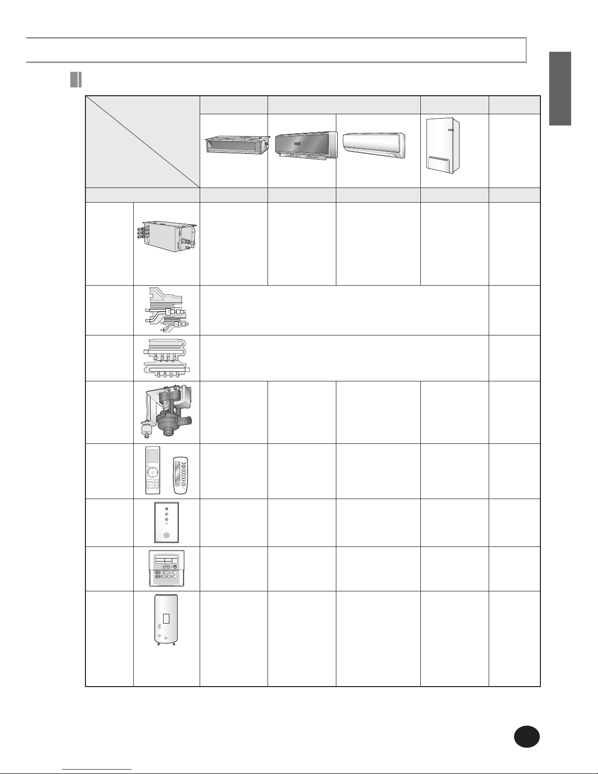
Subsidiary materials compatibility
Subsidiary materials are compatible with CAC, DVM and FJM products.
Install distribution kit for 1, 2 or 3 rooms on the ceiling or outdoor area.
A2W:Air to Water
A2A:Air to Air
Duct Wall mounted Air to Water unit Remark
Slim Duct Vivace Neo-Forte Hydro Unit
Capacity 2.2~5.6kW 2.2~7.1kW 2.2~7.1kW 8/16kW
EEV Kit
EEV kit for 2/3 room
-
MXD-A13K116B
MXD-A13K200B
MXD-A16K200B
MXD-A13K216B
MXD-A13K300B
MXD-A16K231B
MXD-A16K300B
≤3.6kW 1room + ≥5.6kW 1room
≤3.6kW x 2room
≥5.6kW x 2room
≤3.6kW 2room + ≥5.6kW 1room
≤3.6kW x 3room
≤3.6kW 1room + ≥5.6kW 2room
≥5.6kW 3room
- Requisite
Y-joint
MXJ-YA1509K
(≤15.0kW and below)
Requisite
Header-
joint
MXJ-HA2512K
(Below 46.4 kW)
Option
Drain Pump MDP-E075SEE
- -
- Option
Wireless
remote
controller
MR-BH01
Included Included
- Option
Remote
controller
receive kit
MRK-A00 - -
- Option
Wired
remote
controller
MWR-TH01 - -
Included Option
Domestic
Hot
Water tank
DHW tank
(200/300L,
200/300S)
-
- -
NH300WHXES
NH300WHXEA
NH200WHXES
NH200WHXEA
Option
Indoor unit
Subsidiary materials
E-8
Locating the Units
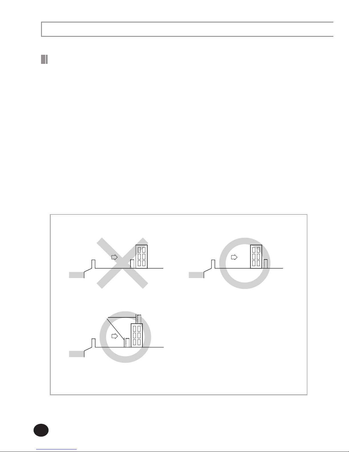
Deciding on Where to Install the Outdoor Unit
- Install the outdoor unit in a place (such as near buildings etc.) where it can be prevented
from sea breeze which can damage the outdoor unit.
- If you cannot avoid installing the outdoor unit by the seashore, construct a protection wall
around to block the sea breeze.
- Install the outdoor unit in a place where water can drain smoothly.
Protection wall should be constructed with a solid
material such as concrete to block the sea breeze
and the height and the width of the wall should be
1.5 times larger than the size of the outdoor unit.
Also, secure over 700mm between the protection
wall and the outdoor unit for exhausted air to
ventilate.
Sea
Sea
breeze
Outdoor
unit
Sea
Sea
breeze
Outdoor
unit
Sea
Sea
breeze
Outdoor
unit
Protection wall
If you cannot find a place satisfying above conditions, please contact manufacturer. Make sure to
clean the sea water and the dust on the outdoor unit heat exchanger.
Decide the installation location regarding the following condition and obtain the user’s approval.
The outdoor unit must not be placed on its side or upside down, as the compressor lubrication oil
will run into the cooling circuit and seriously damage the unit.
Choose a location that is dry and sunny, but not exposed to direct sunlight or strong winds.
Do not block any passageways or thoroughfares.
Choose a location where the noise of the Air to water heat pump when running and the
discharged air do not disturb any neighbours.
Choose a position that enables the pipes and cables to be easily connected to the indoor unit.
Install the outdoor unit on a flat, stable surface that can support its weight and does not generate
any unnecessary noise and vibration.
Position the outdoor unit so that the air flow is directed towards the open area.
Place the outdoor unit where there are no plants and animals because they may cause
malfunction of outdoor unit.
Maintain sufficient clearance around the outdoor unit, especially from a radio, computer, stereo
system, etc.
When installing the outdoor unit near seashore, make sure it is not directly exposed to sea breeze.
If you can not find a adequate place without direct see breeze, make sure to apply anti-corrosion
coating on the heat exchanger.
E-9
ENGLISH
Do not install the Air to Water Heat pump in following places.
- The place where there is mineral oil or arsenic acid.
There is a chance that parts may get damaged due to burned resin.
The capacity of the heat exchanger may reduce or the Air to Water Heat pump may be out of order.
-
The place where corrosive gas such as sulfurous acid gas generates from the vent pipe or air outlet
The copper pipe or connection pipe may corrode and refrigerant may leak.
- The place where there is a danger of existing combustible gas, carbon fiber or flammable dust.
The place where thinner or gasoline is handled.
Do not install the outdoor unit in a snowy and cold area (low temperature and high humidity
area - where the temperature is below -7°C and humidity is higher than 85%) because
according to operation condition (defrost, etc.), ice may be formed in the drain route.
If the ice is accumulated, it may cause critical damage to the product.
ex) lakeside of cold area in winter time, seashore, alpine region and etc.
Avoid a place that may disturb your neighbor. Noise may occur from the outdoor unit and the
discharged air may run into the neighborhood.
(Be careful of the operation time in a residential area.)
Install the outdoor unit on a hard and even area that can support its weight.
Choose a flat place that rainwater does not settle or leak.
Choose a place avoiding strong winds.
Maintain sufficient space for repairs and service.
Choose a place where you can easily connect the pipes and cables to the indoor unit.
Make sure that the condensed water dripping from the drain hose runs out properly and safely.
If you install the outdoor unit by the sea or a spa, concern about corrosion.
Build a support where may have a heavy snow so that the air intake is not blocked by snow.
Install a protective safety fence to eliminate the possibility of falling.
You have just purchased Air to Water Heat pump and it has been installed by your
installation specialist.
This device must be installed according to the national electrical rules.
With an outdoor unit having net weight upper than 60kg, we suggest do not install it
suspended on wall, but considering floor standing one.
E-10
Locating the Units
(Continued)
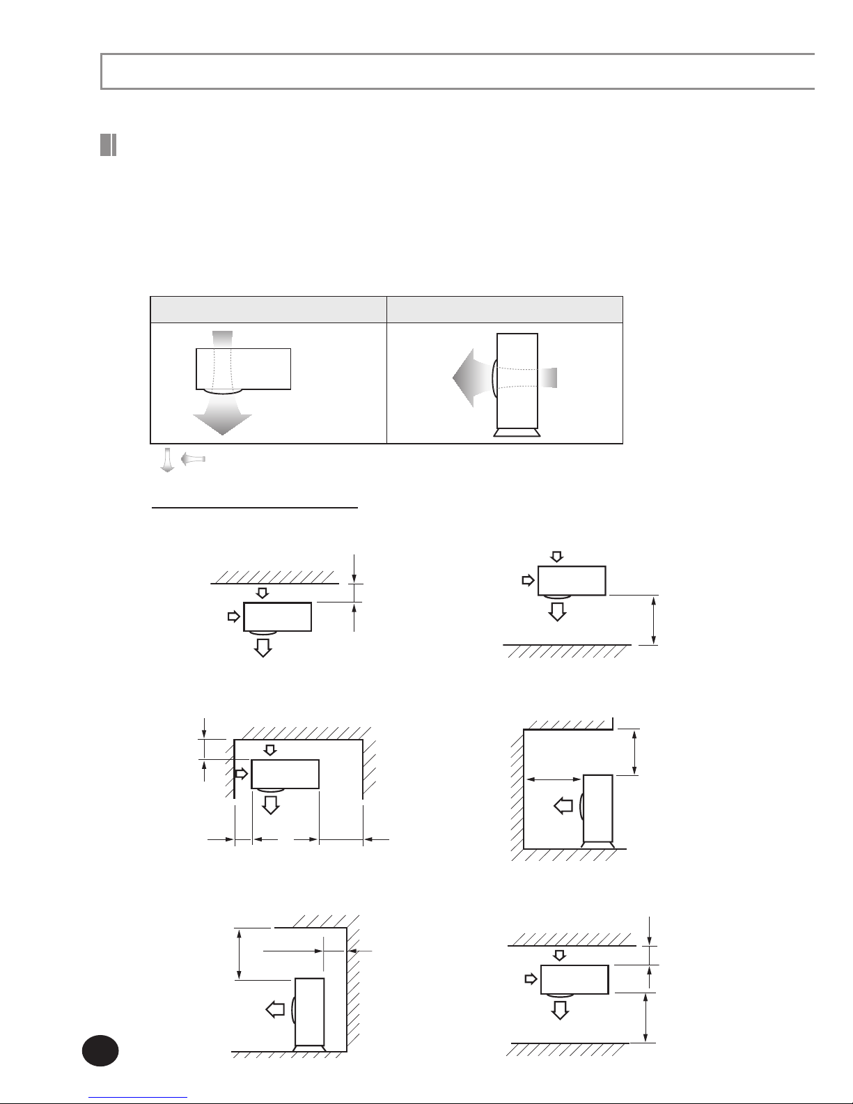
Space Requirements for Outdoor Unit
Observe the clearances and dimensions as seen below when installing the outdoor unit.
If you install several outdoor units simultaneously, observe the space for ventilation and
free airflow.
If the space for ventilation is insufficient, the Air to water heat pump may be inefficient.
SAMSUNG logo is attached on the front side of the outdoor unit.
Figure Description
Top view
Side view
Front side:
Air outlet
Back side:
Air intake
Back side: Air intake
Front side: Air outlet
, Air flow direction.
When installing 1 outdoor unit
300 or more
When the air outlet is opposite the wall
1500 or more
When the air outlet is toward the wall
(Unit : mm)
300 or more
150 or more
600 or more
When 3 sides of the outdoor unit
are blocked by the wall
The upper part of the outdoor unit
and the air outlet is toward the wall
1500 or more
2000 or more
1500 or more 300 or more
When the walls are blocking front and
the rear side of the outdoor unit
500 or more
300 or more
The upper part of the outdoor unit and
the air outlet is opposite the wall
E-11
ENGLISH
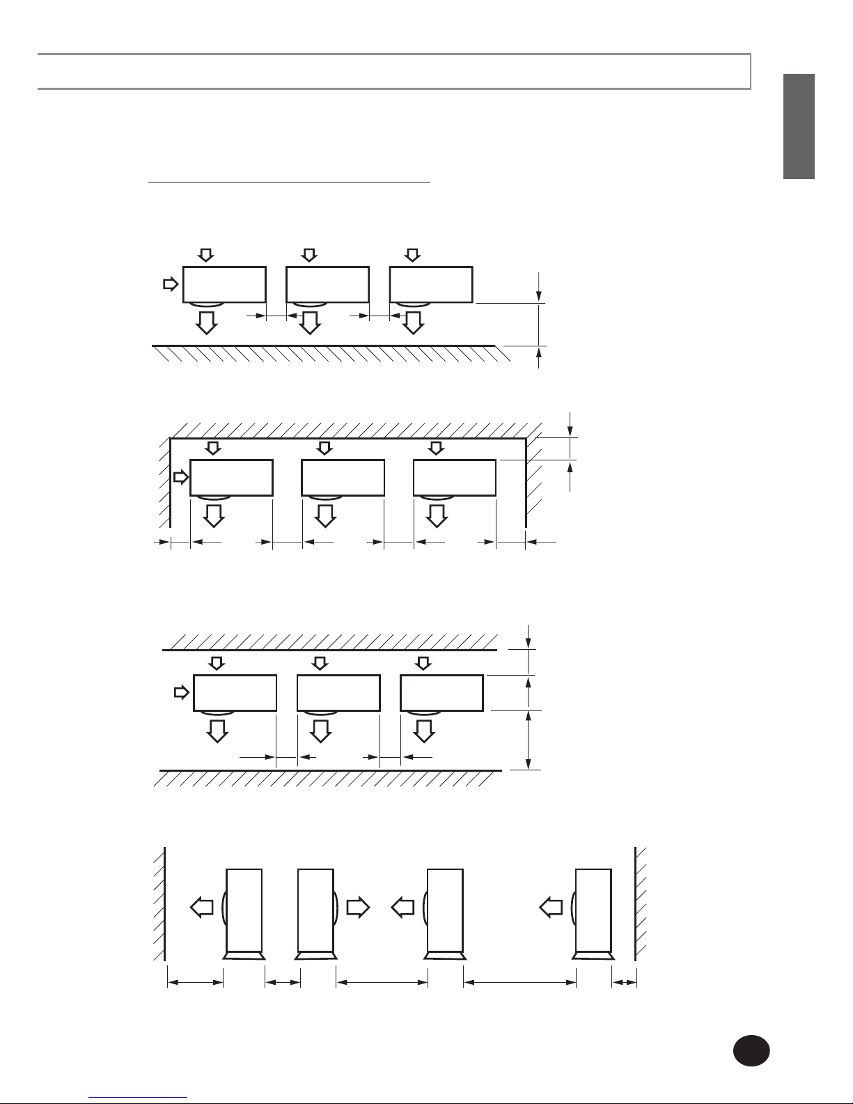
When installing more than 1 outdoor unit
300 or more
300 or more
1500 or more 600 or more 3000 or more 300 or more3000 or more
600 or more 600 or more
300 or more1500 or more
600 or more 600 or more
600 or more
When 3 sides of the outdoor unit are blocked by the wall
When the walls are blocking front and the rear side of the outdoor units
When front and rear side of the outdoor unit is toward the wall
When the air outlet is toward the wall
(Unit : mm)
1500 or more
600 or more 600 or more
E-12
Locating the Units
(Continued)
Selecting Outdoor Unit Combination
Install the Hydro unit only for R410A.
Outdoor unit Heating capacity (kW)
Maximum of connected
indoor units
Total capacity of connected
indoor units (kW)
RD060PHXEA 6.0 3 3.0~6.0
RD070PHXEA 7.0
4 3.5~7.0
RD080PHXEA 8.0
5 4.0~8.0
RD110PHXEA 11.0
5 6.0~11.0
RD140PHXEA 14.0
5 6.4~14.0
RD0160PHXEA 16.0
5 7.2~16.0
You may connect indoor units within 100% of the outdoor unit capacity.
Smallest indoor unit(2.2kW) was used to calculate ‘Maximum of connected indoor units’.
Connect maximum 5 indoor units to the selected outdoor unit.
Total capacity of connected indoor units must be within 130% of the outdoor unit capacity.
If all indoor units operate simultaneously when total capacity of indoor units exceeds 100% of the
outdoor unit, actual capacity of each indoor unit may be reduced a little as compared with its rated
capacity.
General Tools
Vacuum Pump(Backward flowing prevention) Manifold Gauge
Stud Finder Torque Wrench Pipe Cutter
Reamer Pipe Bender Spirit Level
Screw Driver Spanner Drill
L Wrench Measuring Tape
Tools for test operations
Thermometer Resistance Meter
Electroscope
Tools Required for Installation
Moving the Outdoor Unit
Select the moving route.
Secure the strength of the carrying path to resist against the weight of the outdoor unit.
Do not slant the product more than 30˚ when carrying it. (Do not lay the product down sideways.)
The surface of the heat exchanger is sharp. Be careful not to be get injury while moving.
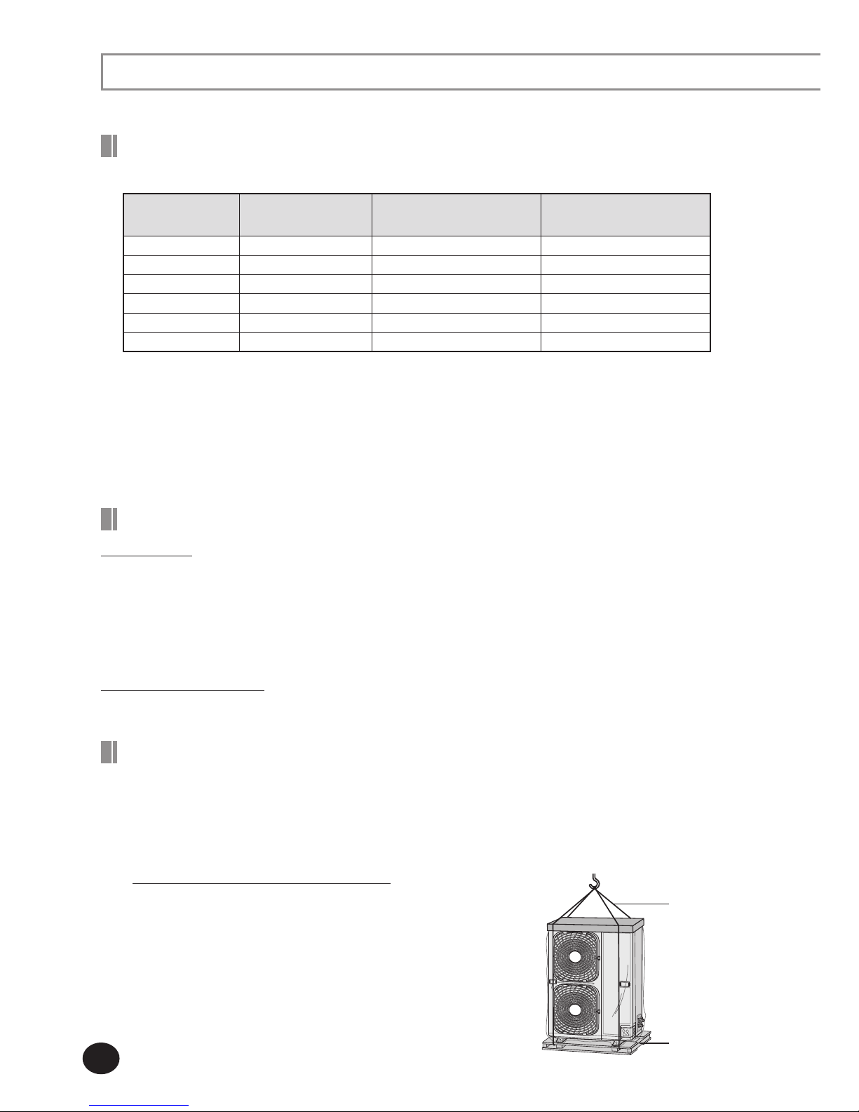
Wire rope/straps
Wood palette
When moving with a crane or straps
In case of placing the outdoor unit on a high ground
such as rooftop
- Fasten the wire rope as seen in the picture.
- Move the product with its package on, to prevent any
damages caused by the rope.
E-13
ENGLISH
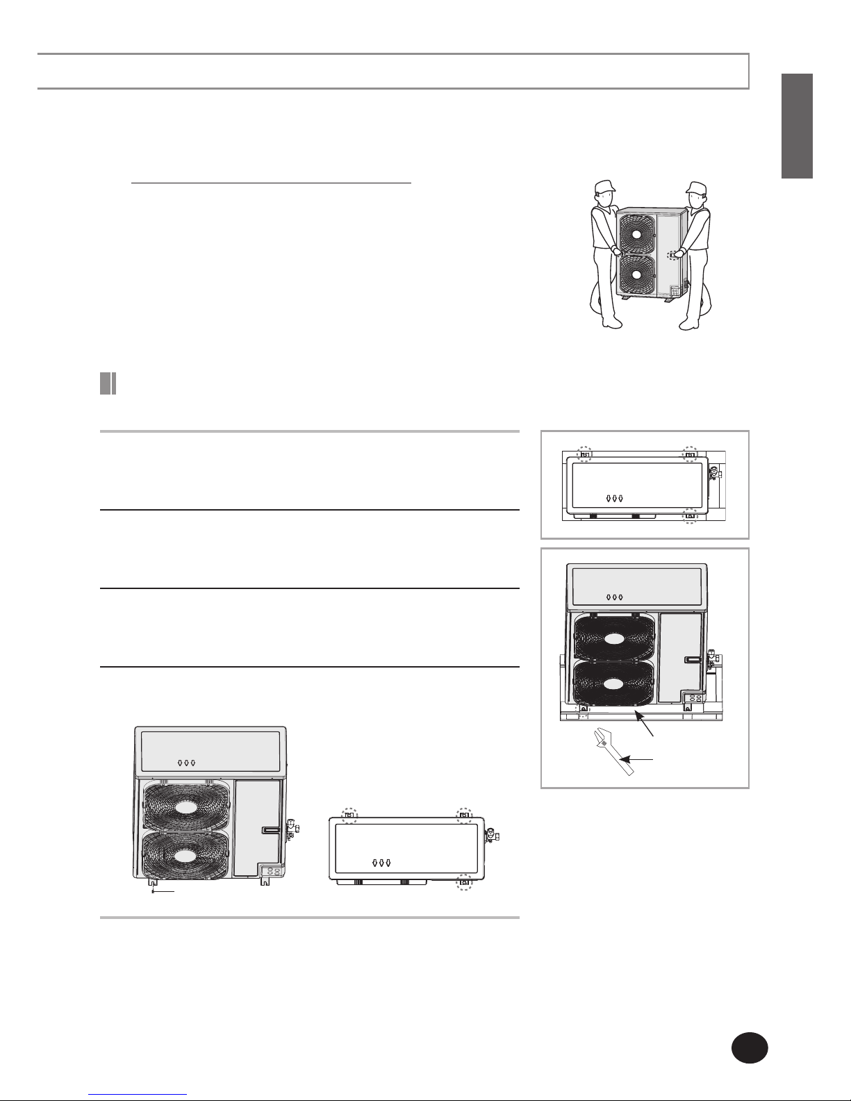
When the moving distance of the product is close enough for
installation personnel to carry.
- 2 people should move the product using the carry handle as
shown in the picture.
- Be careful not to damage the heat exchanger.
- Be careful not to get injured by the sharp edge of the
heat exchanger.
When moving by installation personnel
1
Disassemble the three screws (with an electric driver) which
fixes wood palette.
2
Disassemble the bottom-left screw with monkey spanner.
Do not remove guard fan.
3
After removing the wood palette, move the outdoor unit to
the installation place.
4
Fasten the bottom-left screw with monkey spanner first, and
then fasten the other three anchor bolts.
Screw
Disassembling the Leg Base and Wood Palette /
Fastening the Anchor Bolt
Monkey spanner
Wood palette
E-14
Locating the Units
(Continued)
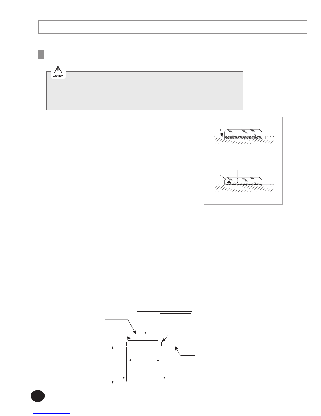
Installing the Outdoor Unit
Install the outdoor unit higher than 150mm from the base
surface and install the drain hole to connect the pipe to the
drainage.
If forward fan outdoor unit is installed where has average
fallen snow 150mm over, outward duct should be attached
to the outdoor unit.
The concrete foundation should be 1.5 times larger than
bottom of the outdoor unit.
When heating, condensed water may be generated.
Pay attention to waterproof and drainage of the
concrete foundation where the outdoor unit is installed.
(An ice road may form on the base surface in winter.)
Make up for wire mash or steel bar so that the
outdoor unit is not damaged or broken when installing
concrete foundation.
When installing the outdoor units in same place simultaneously, install the H beam inside
concrete foundation. (When installing a number of outdoor unit, you can install it on the
concrete foundation.)
Install the H beam(150mm x 150mm x t10 : basic specification) to jut out from the concrete foundation.
After installing the H beam, apply corrosion protection.
Install a square pad(t=20mm or more) to prevent vibration of the outdoor unit delivering to the base
surface when installing the concrete for the outdoor unit.
Place the outdoor unit on the H beam and fix it with the bolt, nut and washer.
Do not install the outdoor unit on a wood palette.
Fix the outdoor unit completely to the base surface with anchor bolts.
The manufacturer is not responsible for the damage occurred by not
keeping standard of the installation.
< When installing on the ground >
Drain hole
150 or more
< When installing on the roof >
Install the outdoor unit
horizontally on
the ground
150 or more
Base mount construction
(Unit : mm)
Outdoor unit
Anchor bolt
Nut, Spring
washer
H beam
Square pad
A+10~20mm or more
A
20mm
75mm
 Loading...