

SAMSUNG RCD-M70 service manual
RADIO CASSETTE RECORDER
CD PLAYER
RCD-M70
SERVICE
Manual
RADIO CASSETTE RECORDER CD PLAYER
CONTENTS
1. Alignment and Adjustments
2. Disassembly and Reassembly
3. Exploded Views and Parts List
4. Electrical Parts List
5. Block Diagrams
6. PCB Diagrams
7. Wiring Diagram
8. Schematic Diagrams

ELECTRONICS
© Samsung Electronics Co.,Ltd. JAN 2001
Printed in Korea
Code no. AH68-20202L

2-1
2. Disassembly and Reassembly
2-1 Front Cabinet
1. Remove the Lid battery of A
2. Remove 9 screws of
! of its rear part
3. Remove 3 screws of @ of its rear part
4. Remove Front/Top Cabinet of B
Fig 2-1
1. Remove Top Cabinet of C to topward.
2-2 Top Cabinet
Samsung Electronics
Fig 2-2
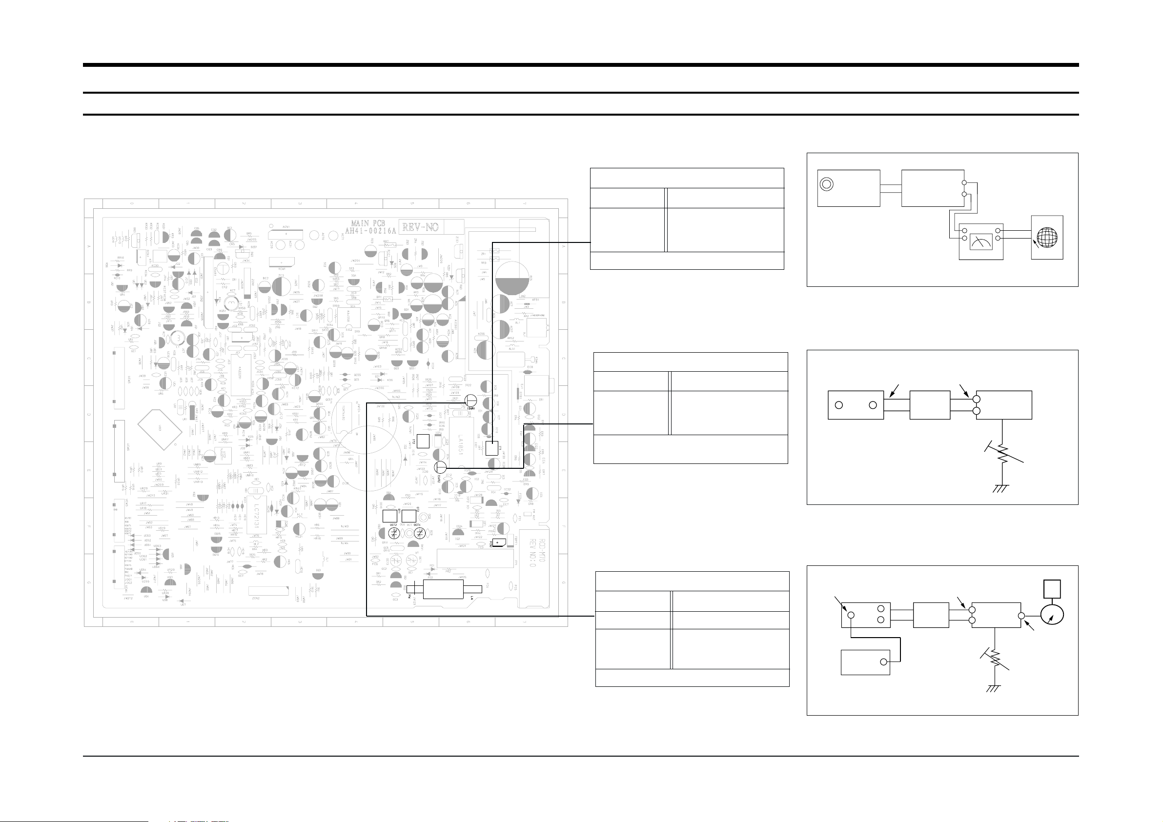
1. Alignment and Adjustments
1-1 Tuner
Samsung Electronics 1-1
FM THD Adjustment
Minimum Distortion (Figure 1-1)
SSG FREQ.
Adjustment
point
(IT1)
98 MHz
FM DETECTOR COIL
FM Stereo Adjustment
L-CH/R-CH : Maximum(Figure 1-3)
SSG FREQ.
Frequency
Adjustment
point
(ISVR1)
98MHz
98MHz
SEMI-VR(5KΩ)
FM Search Level Adjustment
Adjust ISVR2 so that “TUNED” of LCD
is lighted (Figure 1-2)
Figure1-2 FM Auto Search Level Adjustment
Figure1-3 FM Stereo Separation Adjustment
Figure1-1 IF CENTER and THD Adjustment
SSG FREQ.
Adjustment
point
(ISVR2)
98 MHz
BEACON
SENSITIVITY
SEMI-VR(50KΩ)
FM SSG
FM
SSG
75Ω
Dummy
5KΩ
Stereo
Modulator
(Pilot 10%)
OUT
Oscilloscope
FM antenna
SET
Speaker
Terminal
EXT
GND
VTVM
GND
26 dB
FM SSG
Output
GND
Speaker
Terminal
FM
Antenna
Terminal
Distortion Meter
Input
SET
Input
output
Oscilloscope
FM IN
FM Antenna
SET
50 kΩ
FREQ:1KHz
MOD : 40KHz DEV
1-2 Samsung Electronics
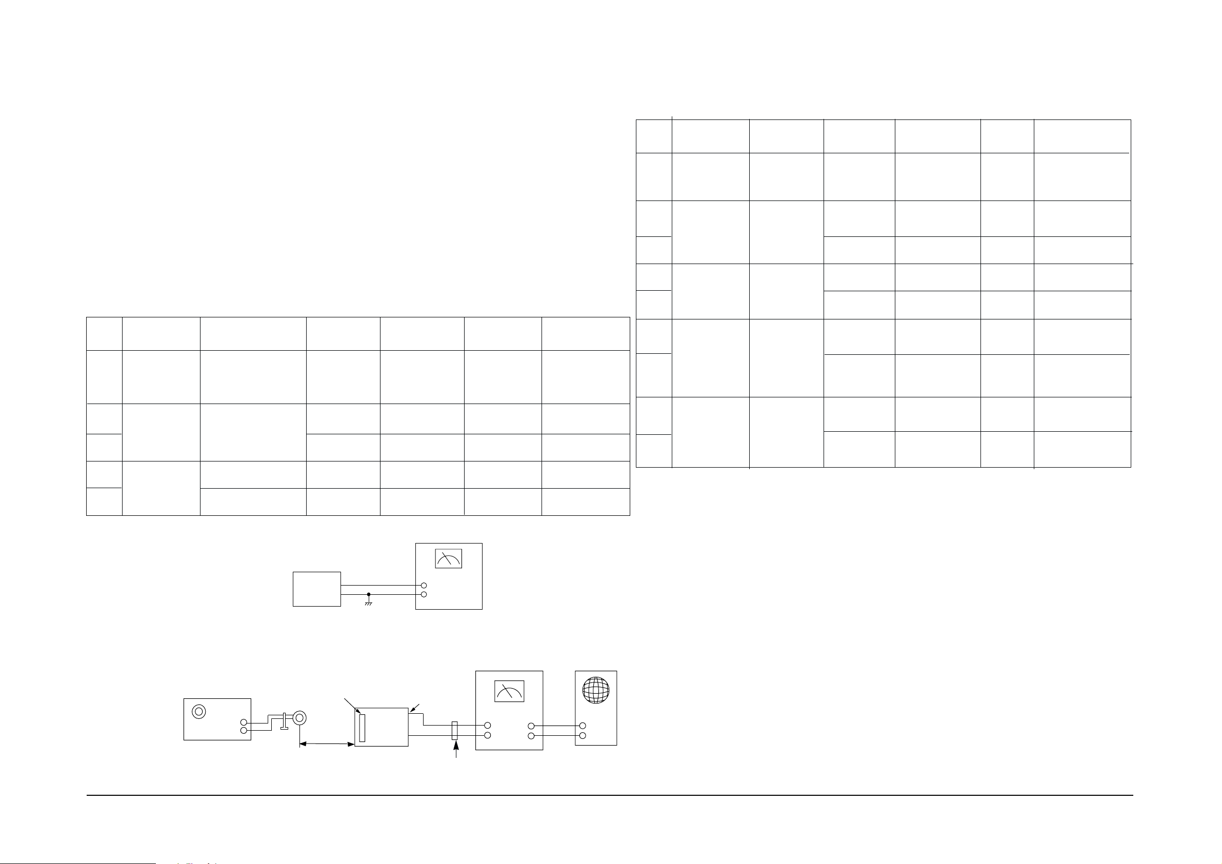
1-1-1 Test Equipment
1-1-2 Pre-Adjustment
1-1-3 AM Adjustment
1. AM Standard Signal Generator (S.S.G) : 400Hz, 30% MOD
2. Oscilloscope
3. VTVM
4. Frequency counter
5. Loop antenna
6. Dummy load (3Ω)
7. DC voltmeter
1. Check the source voltage
2. Press TUNER/BAND to select the AM(MW) function.
3. Set the EQ/S.BASS control to OFF position.
4. Set the volume control to approximaterly 50mw
Intermediate
frequency (IF)
adjustment
AM frequency
coverage
adjustment
AM tracking
adjustment
Figure 1-4
Connect DC voltmeter to AM
VT(OR10) and GND
1
2
4
5
3
Figure 1-5
Figure 1-5
450 KHz
594 KHz
Figure 1-4
SET
60 cm
AM Signal
Generator
Test Loop
Antenna
Speaker
Terminal
VTVM
IN
OUT
GND
Oscilloscope
AM-ANT
Figure 1-5
SET
AM VT(OR10)
GND
Input
DC Voltmeter
594 KHz
MW-ANT
-
-- -
OCT2
1611KHz
-
-
522 KHz
522 KHz
IT 2
OT 1
1.0V
Maximum output
Maximum output
4.6V
Non Adjust
Remark
FREQ. Setting
Adjust. PointSSG.FREQ.Item
Step
Connection
Alignment and Adjustments
Dummy Load(3Ω)
1-1-4 MW/LW
Intermediate
frequency (IF)
adjustment
MW frequency
coverage
adjustment
MW tracking
adjustment
Fig 1-4
1
2
4
5
3
Fig 1-5
594 KHz
594 KHz
MW ANT
COIL
-
OCT2
-
-
LW ANT
COIL
OT1
1.0V(LOW)
Maximum output
Maximum output
Remark
FREQ. Setting
Adjust.
Point
SSG.FREQ.
Item
Step
Connection
522 KHz
4.6V(HIGH)
1611 KHz
1404 KHz
NON Adjust
6
Fig 1-4
-
144 KHz
OT2
0.7V(LOW)
-
290 KHz
OCT4
3.1V(HIGH)
LW frequency
coverage
adjustment
7
9
8
LW tracking
adjustment
Fig 1-5
170KHz
170 KHz
270KHz
-
-
Fig 1-5
450 KHz 522 KHz
IT2
Maximum output
NON Adjust

Samsung Electronics 1-3
1-2 Cassette Deck
Alignment and Adjustments
1-2-1. Recording BIAS adjustment
1) Connect frequency counter to KC433 (See Fig.1-6)and press the Record button.
2) Adjust KT431 (BIAS OSC COIL) until frequency counter reads 50KHz.
1-2-2. Tape AZIMUTH adjustment
1) Connect the equipments as per Fig.1-8 to adjust the tape azimuth with
test tape (recorded at 6.3KHz : MTT-113N)
2) Play the test tape after inserting in DECK.
3) Adjust the azimuth ajustment screw of left side of record/play head for maximum
output and for the same channel phase. (see Fig.1-7)
1-2-3. Tape speed adjustment
1) Connect the equipments as shown in Fig.1-8 adjust the tape speed with
test tape (recorded at 3KHz : MTT-111N)
Fig.1-6 Recording bias adjustment
Fig.1-8
Fig.1-7 Azimuth speed adjustment
50KHz
FREQUENCY
COUNTER
PRE/REC PART
KC433
Adjustment
Adjustment screw
R/P head
UNIT
UNDER TEST
VTVM
OSCILLOSCOPE
FREQUENCY
COUNTER
3000Hz

Samsung Electronics
3-1
3.Exploded Views and Parts List
3-1 Cassette Deck Exploded View and Parts List
No. Code No. Description Specification Remarks
AH59-20005X DECK-CASSETTE YN21ZSW-77
1 AH81-11037D R.F PULLEY ASS’Y 8521-200090-300
2 AH81-11154D BELT SUB 6600-090014-001
3 AH81-11037H CAM GEAR 6021-200802-001
4 AH81-11037J S REEL ASS’Y 8521-200080-300
5 AH81-11037K T REEL ASS’Y 8521-200070-300
6 AH81-11154E BELT MAIN 6600-090020-001
7 AH81-11150W R/P HEAD TC-951
8 AH81-11150X ERASE HEAD TC-230AN
9 AH81-11037Q MOTOR EG530YD2BH
3-1-1 AUTO STOP(OPTION)
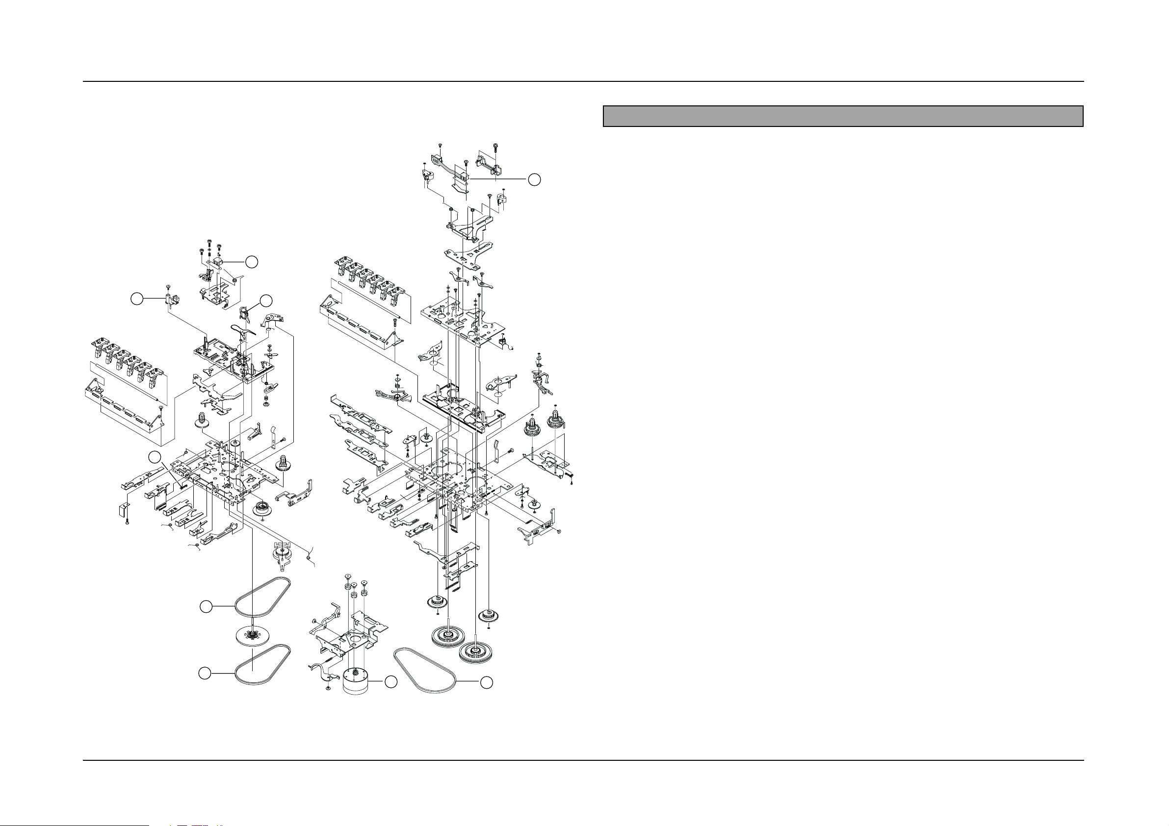
3-2 Samsung Electronics
3-1-2 AUTO REVERSE(OPTION)
1
3
4
5
6
7
8
9
2
No. Code No. Description Specification Remarks
1
2
3
4
5
6
7
8
9
AH59-20006V
AH81-10005W
AH81-10005Z
AH81-10006C
AH81-10006R
AH81-11037Q
AH81-10022E
AH81-10022H
AH81-10022T
AH81-10023W
TAPE DECK ASS’Y
LEAF SWITCH
PINCH ROLLER ARM ASS’Y
RF BLET
MAIN BELT
MOTOR
R/P HEAD
P/B HEAD
E-HEAD
MAIN BELT
YN921ZSW-50
MSW-1541T
1921-04-301
1921-07-03
1821-12-173
EG530YD2B
MS15R-AA2N1
MR359-KF243
PHK380-MS16A
1821-17-03
 Loading...