

Samsung NS100HHXEH, RC125DHXEH, RC100DHXEH, NS125HHXEH, NS140HHXEH Service Manual
...
SYSTEM AIR CONDITIONER
AIR CONDITIONER CONTENTS
Refer to the service manual in the GSPN(see the rear cover) for the more information.
1. Precautions
2. Product Specifications
3. Disassembly and Reassembly
4. Troubleshooting
5. Exploded Views and Parts List
6. PCB Diagram and Parts List
7. Wiring Diagram
8. Schematic Diagram
9. Reference Sheet
Basic : NS140HHXEA/RC140DHXEA
Model :
NS100HHXEH RC100DHXEH
NS125HHXEH RC125DHXEH
NS140HHXEH RC140DHXEH
NS155HHXEH RC155DHXEH
NS180HHXEH RC180DHXGH
Model Code :
NS100HHXEH/XSA RC100DHXEH/XSA
NS125HHXEH/XSA RC125DHXEH/XSA
NS140HHXEH/XSA RC140DHXEH/XSA
NS155HHXEH/XSA RC155DHXEH/XSA
NS180HHXEH/XSA RC180DHXGH/XSA
NS100HHXEH
NS125HHXEH
NS140HHXEH
NS155HHXEH
RC100DHXEH
RC125DHXEH
RC140DHXEH
RC155DHXEH
RC180DHXGH
NS180HHXEH

2 Samsung Electronics
Contents
1. Precautions . . . . . . . . . . . . . . . . . . . . . . . . . . . . . . . . . . . . . . . . . . . . . . . . . . . . . . . . . . . . . . . . . . . . . . . . . . .1-1
1-1 Installing the air conditioner . . . . . . . . . . . . . . . . . . . . . . . . . . . . . . . . . . . . . . . . . . . . . . . . . . . . . . . . . . . . . . 1-1
1-2 Power supply and circuit breaker . . . . . . . . . . . . . . . . . . . . . . . . . . . . . . . . . . . . . . . . . . . . . . . . . . . . . . . . . . 1-1
1-3 During operation . . . . . . . . . . . . . . . . . . . . . . . . . . . . . . . . . . . . . . . . . . . . . . . . . . . . . . . . . . . . . . . . . . . . . . . . . 1-2
1-4 Disposing of the unit . . . . . . . . . . . . . . . . . . . . . . . . . . . . . . . . . . . . . . . . . . . . . . . . . . . . . . . . . . . . . . . . . . . . . . 1-2
1-5 Others . . . . . . . . . . . . . . . . . . . . . . . . . . . . . . . . . . . . . . . . . . . . . . . . . . . . . . . . . . . . . . . . . . . . . . . . . . . . . . . . . . . . 1-2
2. Product Specifi cations . . . . . . . . . . . . . . . . . . . . . . . . . . . . . . . . . . . . . . . . . . . . . . . . . . . . . . . . . . . . . . . . . 2-1
2-1 The Feature of Product . . . . . . . . . . . . . . . . . . . . . . . . . . . . . . . . . . . . . . . . . . . . . . . . . . . . . . . . . . . . . . . . . . . . 2-1
2-2. Product Specifi cations . . . . . . . . . . . . . . . . . . . . . . . . . . . . . . . . . . . . . . . . . . . . . . . . . . . . . . . . . . . . . . . . . . . . 2-2
2-3 Accessory and Specifi cations . . . . . . . . . . . . . . . . . . . . . . . . . . . . . . . . . . . . . . . . . . . . . . . . . . . . . . . . . . . . . . 2-5
3. Disassembly and Reassembly . . . . . . . . . . . . . . . . . . . . . . . . . . . . . . . . . . . . . . . . . . . . . . . . . . . . . . . . . . 3-1
3-1 Indoor Unit . . . . . . . . . . . . . . . . . . . . . . . . . . . . . . . . . . . . . . . . . . . . . . . . . . . . . . . . . . . . . . . . . . . . . . . . . . . . . . . 3-2
4. Troubleshooting . . . . . . . . . . . . . . . . . . . . . . . . . . . . . . . . . . . . . . . . . . . . . . . . . . . . . . . . . . . . . . . . . . . . . . 4-1
4-1 Setting an indoor unit address and installation option . . . . . . . . . . . . . . . . . . . . . . . . . . . . . . . . . . . . . 4-1
4-2 Option code Setting . . . . . . . . . . . . . . . . . . . . . . . . . . . . . . . . . . . . . . . . . . . . . . . . . . . . . . . . . . . . . . . . . . . . . . 4-4
4-3 Indoor Display Error and Check Method . . . . . . . . . . . . . . . . . . . . . . . . . . . . . . . . . . . . . . . . . . . . . . . . . . . 4-5
4-4 Outdoor Display Error and Check Method . . . . . . . . . . . . . . . . . . . . . . . . . . . . . . . . . . . . . . . . . . . . . . . . . . 4-7
4-5 Items to be checked fi rst . . . . . . . . . . . . . . . . . . . . . . . . . . . . . . . . . . . . . . . . . . . . . . . . . . . . . . . . . . . . . . . . . 4-10
4-6 Fault Diagnosis by Symptom . . . . . . . . . . . . . . . . . . . . . . . . . . . . . . . . . . . . . . . . . . . . . . . . . . . . . . . . . . . . . 4-11
5. Exploded Views and Parts List . . . . . . . . . . . . . . . . . . . . . . . . . . . . . . . . . . . . . . . . . . . . . . . . . . . . . . . . . .5-1
5-1 Indoor Unit . . . . . . . . . . . . . . . . . . . . . . . . . . . . . . . . . . . . . . . . . . . . . . . . . . . . . . . . . . . . . . . . . . . . . . . . . . . . . . . 5-1
5-2 Outdoor Unit . . . . . . . . . . . . . . . . . . . . . . . . . . . . . . . . . . . . . . . . . . . . . . . . . . . . . . . . . . . . . . . . . . . . . . . . . . . . . 5-6
5-3 ASS'Y CONTROL OUT . . . . . . . . . . . . . . . . . . . . . . . . . . . . . . . . . . . . . . . . . . . . . . . . . . . . . . . . . . . . . . . . . . . . . 5-10
6. PCB Diagram and Parts List . . . . . . . . . . . . . . . . . . . . . . . . . . . . . . . . . . . . . . . . . . . . . . . . . . . . . . . . . . . .6-1
6-1 Indoor Unit PCB (NS100/125/140/155HHXEH) . . . . . . . . . . . . . . . . . . . . . . . . . . . . . . . . . . . . . . . . . . . . . . 6-1
6-2 Outdoor Unit PCB . . . . . . . . . . . . . . . . . . . . . . . . . . . . . . . . . . . . . . . . . . . . . . . . . . . . . . . . . . . . . . . . . . . . . . . . . 6-4
7.Wiring Diagram . . . . . . . . . . . . . . . . . . . . . . . . . . . . . . . . . . . . . . . . . . . . . . . . . . . . . . . . . . . . . . . . . . . . . . . . 7-1
8.Schematic Diagram . . . . . . . . . . . . . . . . . . . . . . . . . . . . . . . . . . . . . . . . . . . . . . . . . . . . . . . . . . . . . . . . . . . . 8-1
8-1 INDOOR UNIT . . . . . . . . . . . . . . . . . . . . . . . . . . . . . . . . . . . . . . . . . . . . . . . . . . . . . . . . . . . . . . . . . . . . . . . . . . . . . 8-1
8-2 OUTDOOR UNIT . . . . . . . . . . . . . . . . . . . . . . . . . . . . . . . . . . . . . . . . . . . . . . . . . . . . . . . . . . . . . . . . . . . . . . . . . . . 8-5
9. Preference Sheet . . . . . . . . . . . . . . . . . . . . . . . . . . . . . . . . . . . . . . . . . . . . . . . . . . . . . . . . . . . . . . . . . . . . . . 9-1
9-1 Refrigerating Cycle Diagram . . . . . . . . . . . . . . . . . . . . . . . . . . . . . . . . . . . . . . . . . . . . . . . . . . . . . . . . . . . . . . . 9-1
9-2 Index of Model Name . . . . . . . . . . . . . . . . . . . . . . . . . . . . . . . . . . . . . . . . . . . . . . . . . . . . . . . . . . . . . . . . . . . . . 9-2
9-3 Pressure Graph . . . . . . . . . . . . . . . . . . . . . . . . . . . . . . . . . . . . . . . . . . . . . . . . . . . . . . . . . . . . . . . . . . . . . . . . . . . 9-3
Samsung Electronics 1-1
1. Precautions
1-1 Installing the air conditioner
Users should not install the air conditioner by themselves.
Ask the dealer or authorized company to install the air conditioner
except the window-type air conditioner in U.S.A and Canada.
If you don’t install the air conditioner properly, it may cause a fire, a
water leakage or an electric shock.
You must install the air conditioner according to the national wiring
regulations and safety regulations.
Install the indoor unit higher than 2.5m from the floor to avoid the
injury caused by the operation of the fan. (except the window-type
air conditioner)
The manufacturer is not responsible for any accidents or injury caused
by an incorrect installation.
When installing the built-in type air conditioner, keep all electric
cables such as the power cable and the connection cord in pipes,
ducts, or cable channels to protect them from the danger of impact
or any other incidents.
1-2 Power supply and circuit breaker
If the power cord of the air conditioner is damaged, it must be replaced
by the manufacturer or a qualified person in order to avoid a hazard.
The air conditioner must be plugged into an independent circuit if appli-
cable or connect the power cable to the auxiliary circuit breaker.
An all pole disconnection from the power supply must be incorpo-
rated in the fixed wiring with a contact opening of >3mm.
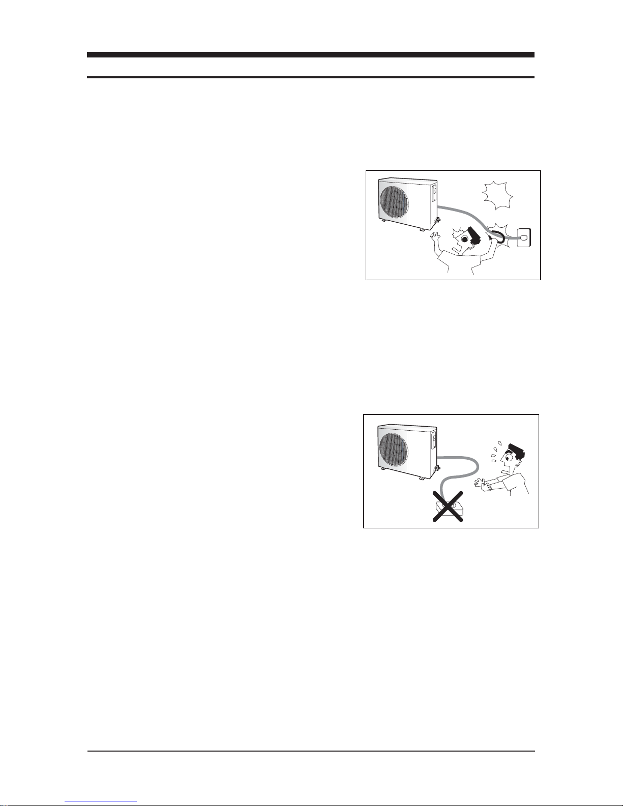
Do not extend an electric cord to the air conditioner.
The air conditioner must be plugged in after you complete the installa-
tion.
suoregnad
Avoid Dangerous Contact
No Tapping and No Extension Cords
1-2 Samsung Electronics
1-4 Disposing of the unit
Before throwing out the air conditioner, remove the batteries from the remote control.
When you dispose of the air conditioner, consult your dealer. If pipes are removed incorrectly, refrigerant may blow out and cause
air pollution. When it contacts with your skin, it can cause skin injury.
The package of the air conditioner should be recycled or disposed of properly for environmental reasons.
1-5 Others
Never store or load the air conditioner upside down or sideways to prevent the damage to the compressor.
Young children or infirm persons should be always supervised when they use the air conditioner.
Max current is measured according to IEC standard for safety.
Current is measured according to ISO standard for energy efficiency.
1-3 During operation
Do not repair the air conditioner at your discretion.
It is recommended to contact a service center directly.
Never spill any kind of liquid on the air conditioner.
If this happens, turn off the air conditioner and contact an authorized ser-
vice center.
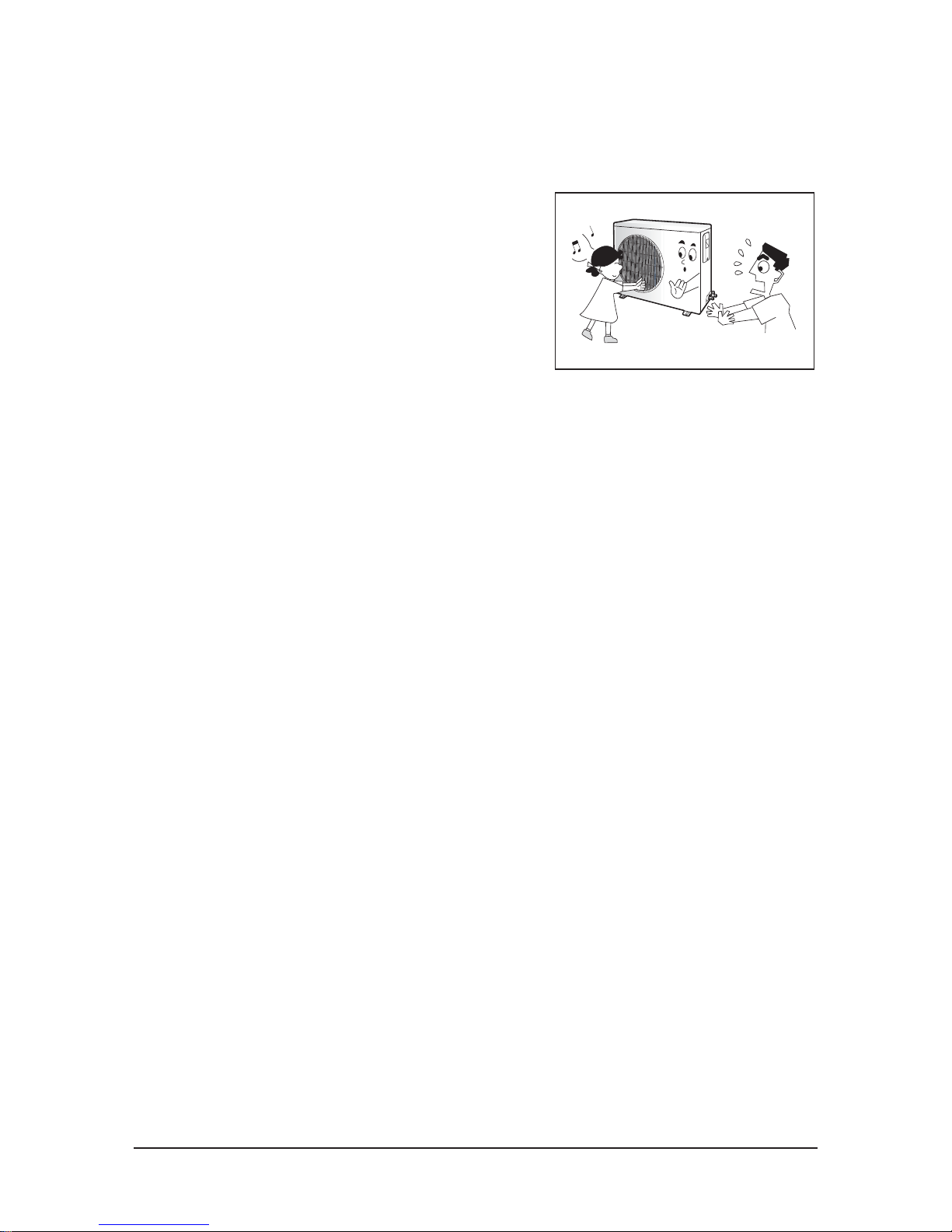
Do not insert anything between the airflow blades to prevent damage
of the inner fan and consequent injury. Keep children away from the air
conditioner.
Do not place any obstacles in front of the air conditioner.
Do not spray any kind of liquid into the indoor unit. If this happens, turn
off the air conditioner and contact a service center.
Make sure that the air conditioner is well ventilated at all times:
Do not place a cloth or other materials over it.
Remove the batteries if you don’t use the remote control for a long time.
(If applicable)
Use the remote control within 7 meters from the indoor unit.
(If applicable)
No children Nearby

Samsung Electronics 2-1
2. Product Specifications
2-1 The Feature of Product
Built-in Cassette Type
After installed, the air conditioner can be harmonized with a room interior.
High Performance & Energy Saving
With the advanced BLDC inverter technology, it makes a room cool with highly energy saving and arises the efficiency of air
conditioner.
Long Piping(Length & Height)
It can give the benefit to the installers and aries the reliability of the air conditioner.
Long Ambient Operation(In Low Temperature)
It can arise the reliability and the capacity of the air conditioner, especially operated in low temperature.
Eco-friendly Product(Lead-Free, RoHS, WEEE)

2-2 Samsung Electronics
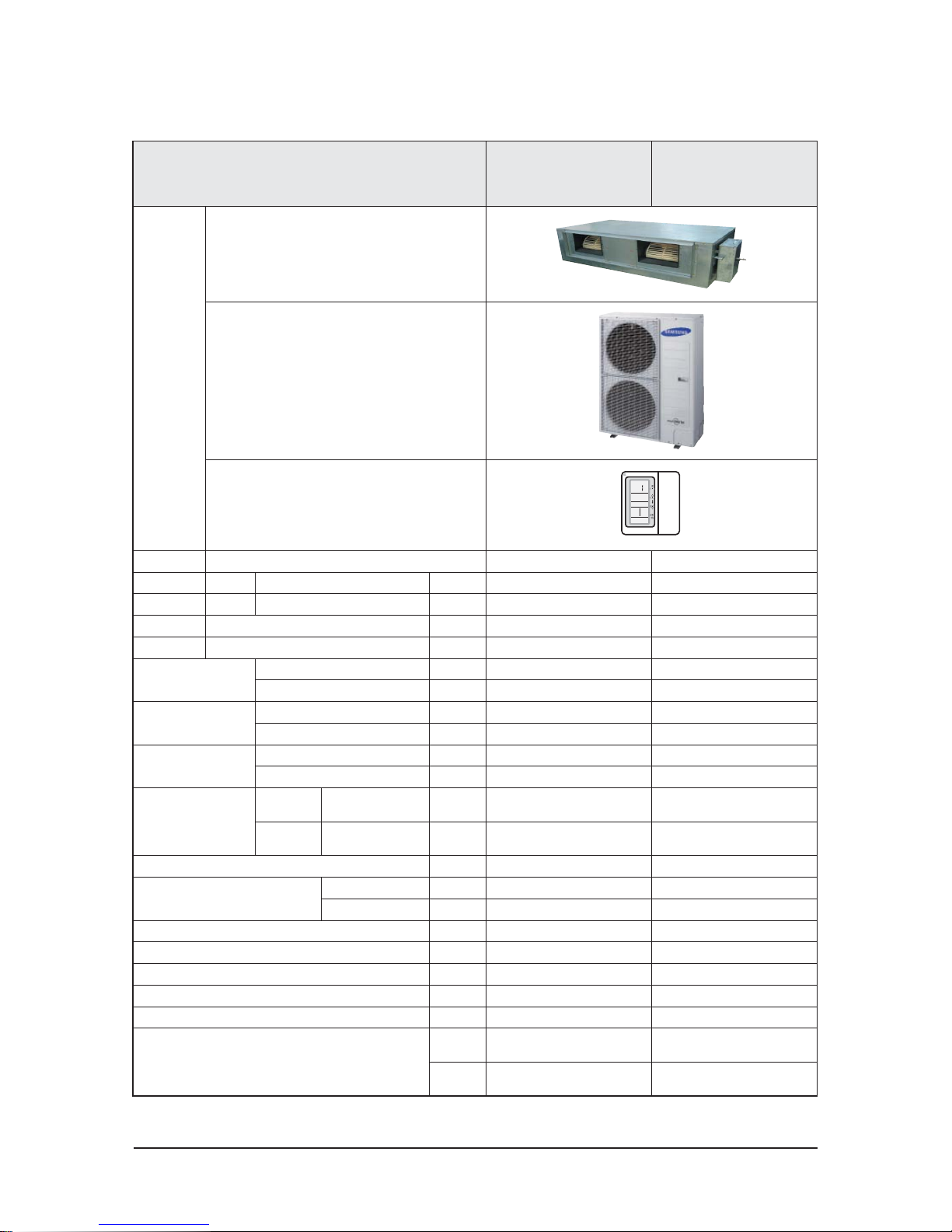
2-2. Product Specifications
ITEM
NS100HHXEH/XSA
RC100DHXEH/XSA
NS125HHXEH/XSA
RC125DHXEH/XSA
IMAGE
Indoor Unit
Outdoor Unit
Remote Controller
Power Product 1Φ, 220-240V/50Hz 1Φ, 220-240V/50Hz
Indoor unit Product L x H x D mm 1200 X 650 X 360 1200 X 650 X 360
Outdoor unit Product L x H x D mm 940 x 1,210 x 330 940 x 1,210 x 330
Indoor unit Product kg(Net) 62.0 65.0
Outdoor unit Product kg(Net) 88.0 88.0
Capacity
Cooling(STD) W 10,000 12,500
Heating(STD) W 11,200 14,000
Power consumption
Cooling(STD) W 2,700 3,850
Heating(STD) W 2,870 3,780
Operation current
Cooling(STD) A 12.2 17.0
Heating(STD) A 12.9 16.5
Noise
(Cooling/Heating)
Indoor
unit
In case of strongest
air blow
dB 53/53 55/55
Outdoor
unit
In case of strongest
air blow
dB 58/60 59/61
Refrigerant g 3,400 3,400
Connecting Pipe
Liquid mm 9.52 9.52
Gas mm 19.05 19.05
Additional Refrigerant(g/m) g/m 50 50
Standard m 7.5 7.5
Extension length(Total) m 75 75
Extension length(Elevation) m 30 30
Air flow rate at 150Pa liter/s 600 750
Option Code
Product Op-
tion
011014-15624F-276470-370000 011034-156123-277D8C-370000
Installation
Option
020000-100000-200000-300000 020000-100000-200000-300000
Samsung Electronics 2-3
ITEM
NS140HHXEH/XSA
RC140DHXEH/XSA
NS155HHXEH/XSA
RC155DHXEH/XSA
IMAGE
Indoor Unit
Outdoor Unit
Remote Controller
Power Product 1Φ, 220-240V/50Hz 1Φ, 220-240V~/50Hz
Indoor unit Product L x H x D mm 1200 X 650 X 360 1200 X 650 X 360
Outdoor unit Product L x H x D mm 940 x 1420 x 330 940 x 1420 x 330
Indoor unit Product kg(Net) 65.0 65.0
Outdoor unit Product kg(Net) 99.0 99.0
Capacity
Cooling(STD) W 14,000 15,500
Heating(STD) W 16,000 17,000
Power consumption
Cooling(STD) W 4,310 4,770
Heating(STD) W 4,320 4,720
Operation current
Cooling(STD) A 19.0 21.5
Heating(STD) A 19.0 21.0
Noise
(Cooling/Heating)
Indoor
unit
In case of strongest
air blow
dB 56/56 56/56
Outdoor
unit
In case of strongest
air blow
dB 63/63 63/63
Refrigerant g 4,400 4,400
Connecting Pipe
Liquid mm 9.52 9.52
Gas mm 19.05 19.05
Additional Refrigerant(g/m) g/m 50 50
Standard m 7.5 7.5
Extension length(Total) m 75 75
Extension length(Elevation) m 30 30
Air flow rate at 150Pa liter/s 800 840
Option Code
Product Op-
tion
011034-116189-278CA0-370000 011034-116189-279BAA-370000
Installation
Option
020000-100000-200000-300000 020000-100000-200000-300000
Product Specifications (cont.)

2-4 Samsung Electronics
ITEM
NS180HHXEH/XSA
RC180DHXGH/XSA
IMAGE
Indoor Unit
Outdoor Unit
Remote Controller
Power Product 3Φ, 380~415V/50Hz
Indoor unit Product L x H x D mm
1240*470*1040
Outdoor unit Product L x H x D mm
940*1420*330
Indoor unit Product kg(Net)
95.0
Outdoor unit Product kg(Net)
101.0
Capacity
Cooling(STD) W
17,500
Heating(STD) W
21,000
Power consumption
Cooling(STD) W
5,470
Heating(STD) W
6,000
Operation current
Cooling(STD) A
9.1
Heating(STD) A
9.9
Noise
(Cooling/Heating)
Indoor
unit
In case of strongest
air blow
dB
56/56
Outdoor
unit
In case of strongest
air blow
dB
65/65
Refrigerant g
4,800
Connecting Pipe
Liquid mm 9.52
Gas mm
19.05
Additional Refrigerant(g/m) g/m 50
Standard m
7.5
Extension length(Total) m 75
Extension length(Elevation) m 30
Air flow rate at 150Pa liter/s 1,050
Option Code
Product Op-
tion
011074-1660C6-27B4D2-370000
Installation
Option
020000-100000-200000-300000
Product Specifications (cont.)
Samsung Electronics 2-5
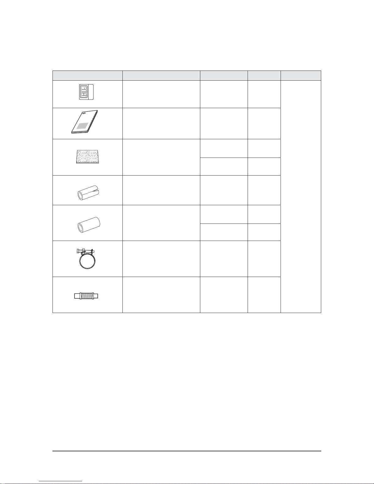
2-3 Accessory and Specifications
■ NS100HHXEH/XSA, NS125HHXEH/XSA, NS140HHXEH/XSA, NS155HHXEH/XSA
Item Descriptions Code-No. Q'TY Remark
Wired remote controller DB97-15070D
1
Indoor
Unit
User&install Manual DB98-33882A
1
Insulation
DB62-03439N
1
DB62-03440N
1
Insu Pipe Joint Out DB62-03439J
2
Insu Pipe Joint In
DB72-00143D
1
DB72-00143E
1
Ass'y Holder Drain Pipe DB90-02064A
1
Ass'y Drain Hose Joint DB94-00758B
1
O
W
N
ER
'
S
I
N
ST
R
U
C
T
I
O
N
S
M
A
N
U
A
L
D
E
I
N
STR
U
C
C
I
O
N
E
S
I
S
T
R
U
Z
I
O
N
I
PER
L
'
U
SO
M
A
N
U
A
L
D
E
I
N
STR
U
‚
Í
E
S
M
A
N
U
EL
D
'
U
TI
L
I
S
A
T
I
O
N
G
EB
R
A
U
C
H
S
A
N
W
E
I
S
U
N
G
S
p
l
ut
-ty
p
e
R
o
om
A
i
r
C
o
n
d
i
t
i
on
e
r
A
i
r
e
a
c
o
n
di
c
i
o
n
a
d
o
d
om
Žs
t
i
c
o
s
i
s
te
m
a
S
pl
i
t
C
on
d
i
z
i
o
na
to
r
e
d
'
a
r
i
a
p
e
r
a
m
b
i
e
n
t
i
a
d
u
n
i
t
ˆ
S
e
p
a
r
a
te
A
p
a
r
e
l
h
o
d
e
a
r
c
o
n
d
i
c
i
o
n
a
d
o
ti
p
o
S
p
l
i
t
C
l
i
m
a
ti
s
e
u
r
d
e
t
y
pe
s
Žp
a
r
Ž
G
e
te
i
l
te
r
a
u
m
k
l
i
m
a
a
n
l
a
g
e
2-6 Samsung Electronics
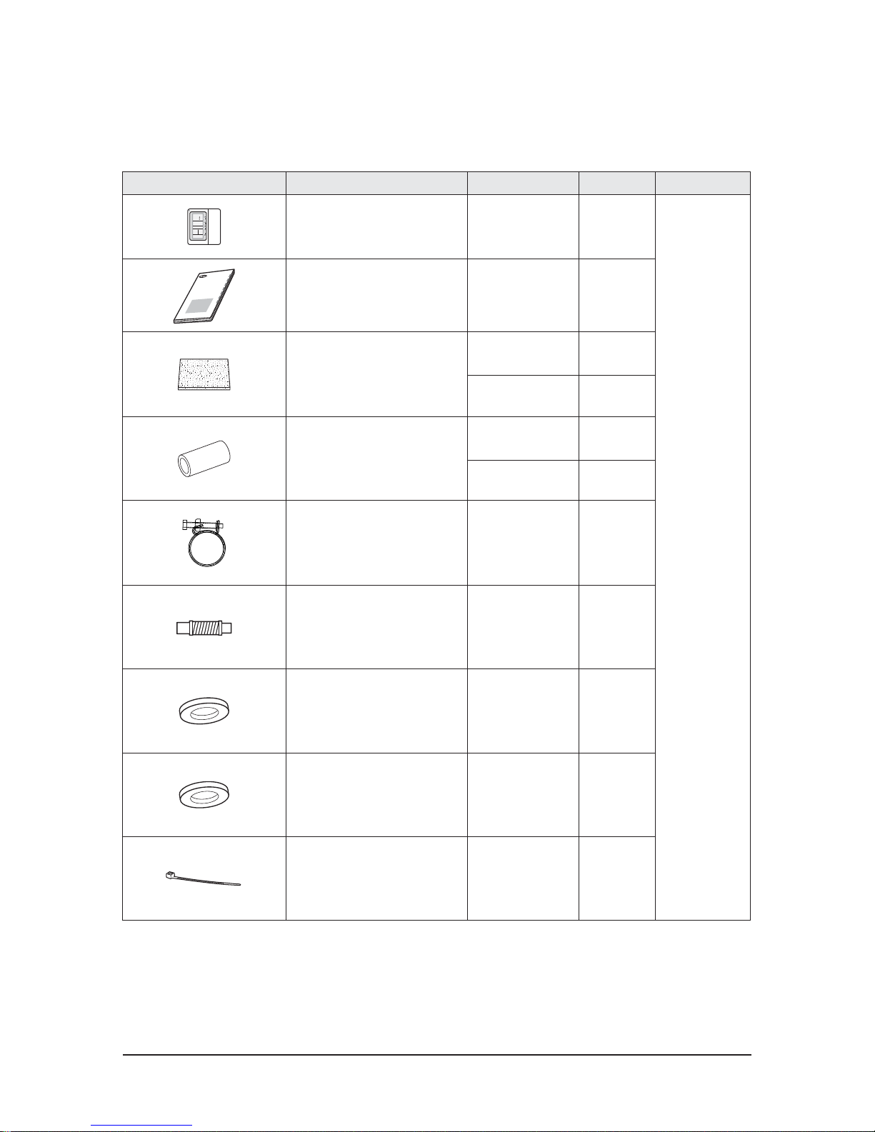
Accessory and Specifications (cont.)
■ NS180HHXEH/XSA
Item Descriptions Code-No. Q'TY Remark
Wired remote controller DB97-15070D
1
Indoor
Unit
O
W
N
ER
'
S
I
N
ST
R
U
C
T
I
O
N
S
M
A
N
U
A
L
D
E
I
N
STR
U
C
C
I
O
N
E
S
I
S
T
R
U
Z
I
O
N
I
P
ER
L
'
U
SO
M
A
N
U
A
L
D
E
I
N
STR
U
‚
Í
ES
M
A
N
U
EL D
'
U
T
I
L
I
S
A
T
I
O
N
G
EB
R
A
U
C
H
S
A
N
W
E
I
SU
N
G
S
p
l
u
t
-
t
y
p
e
R
o
om
A
i
r
C
on
di
ti
o
ne
r
A
i
r
e
a
c
o
n
di
c
i
o
n
a
d
o
d
o
m
Ž
s
ti
c
o
s
i
s
te
m
a
S
pl
i
t
C
on
d
i
z
i
o
n
a
to
r
e
d
'
a
r
i
a
pe
r
a
m
b
i
e
nti
a
d
u
n
i
tˆ
S
e
p
a
r
a
te
A
p
a
r
e
l
h
o
d
e
a
r
c
o
n
d
i
c
i
o
na
d
o
t
i
p
o
S
p
l
i
t
C
l
i
m
a
ti
s
e
u
r
d
e
t
y
p
e
s
Ž
p
a
r
Ž
G
e
te
i
l
te
r
a
u
m
k
l
i
m
a
a
n
l
a
g
e
User&install Manual DB98-33920A
1
Insulation
DB72-00109H
1
DB72-00109G
2
Insu Pipe Joint In
DB72-00143G
2
DB72-00143H
1
Ass'y Holder Drain Pipe DB90-02064A
2
Ass'y Drain Hose Joint DB94-00758A
1
Washer DB81-00667A
8
Grommet Hanger DB63-00237A
4
Cable Tie DB65-10088C
4

Samsung Electronics 2-7
Accessory and Specifications (cont.)
Item Description Code No. Q’ty Remark
Cap Drain DB63-10355C 3
Essential Offer (Out-
door Unit)
Drain Plug DB67-00806A 1
Rubber Leg DB73-20134A 4
2-8 Samsung Electronics
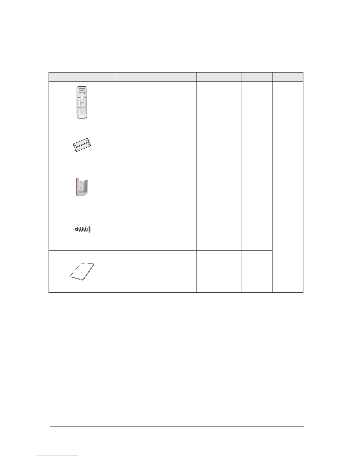
Item Descriptions Code-No. Q'TY Remark
Wireless remote controller
DB93-11115N 1
Optional
Batteries for remote controller
(specifi cation: "AAA" type)
DB47-90024A 2
Remote controller holder
DB61-04899A 1
M4×16 screw
6002-000581 2
User’s manual
DB98-33129A 1
Accessory and Specifications (cont.)
■ Wireless remote controller (MR-DH00) [Code No. : DB97-17546B]

Samsung Electronics 2-9
Item Descriptions Code-No. Q'TY Remark
Central controller
DB93-03425N 1
Optional
Cable tie
DB65-10088B 2
Cable clamp
DB65-10074E 5
M4 X 16 Screw
6002-000474 7
User’s manual
DB98-33437A 1
Installation guide
DB98-33434A 1
Accessory and Specifications (cont.)
■ Central controller (MCM-A202D) [Code No. : DB97-18602B]
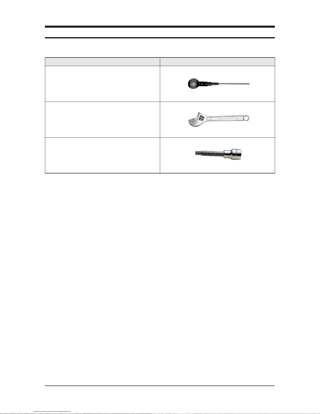
Samsung Electronics 3-1
Item Remarks
+SCREW DRIVER
Adjustable Wrench
(8mm, 10mm, 13mm)
M6, M8 Hex Wrench
■ Necessary Tools
3. Disassembly and Reassembly
3-2 Samsung Electronics
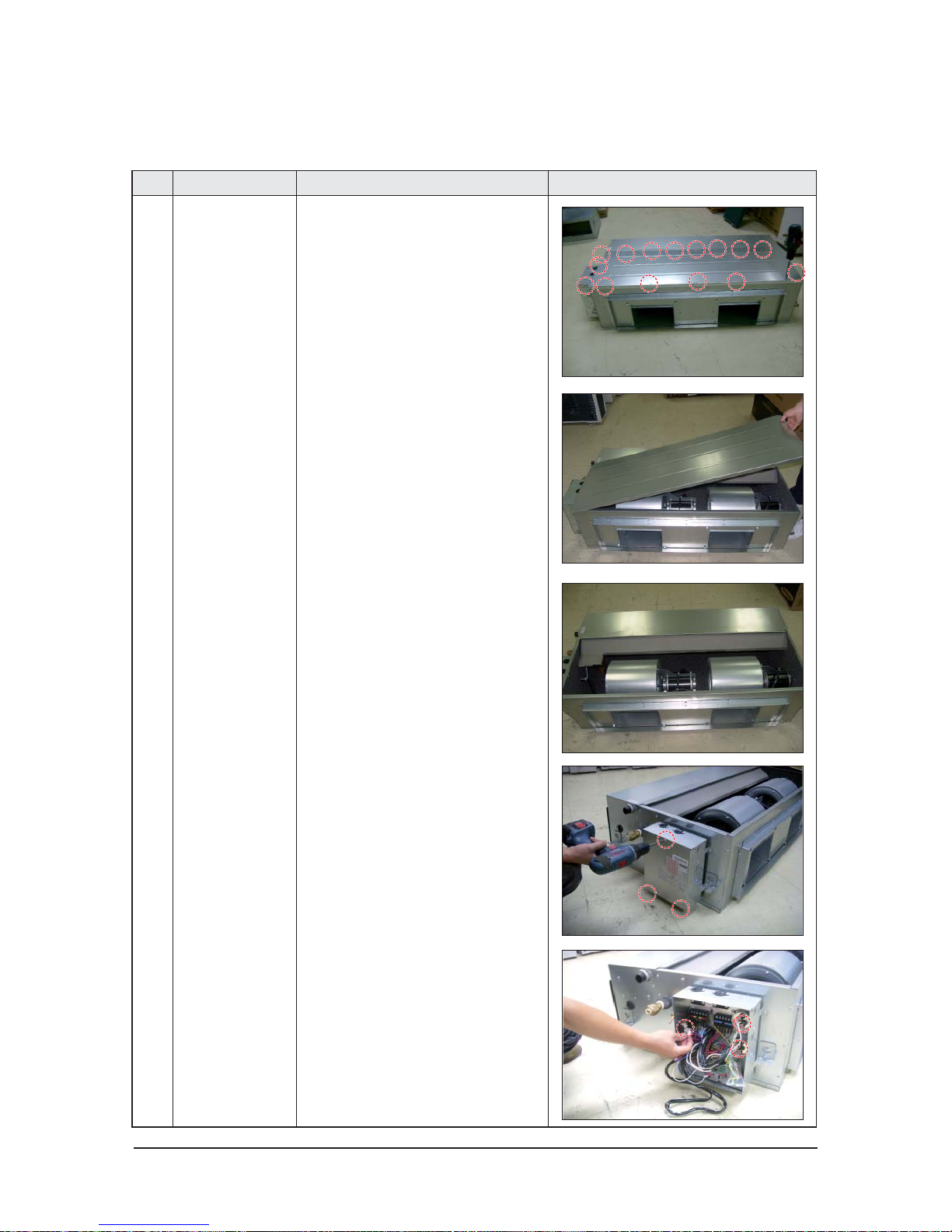
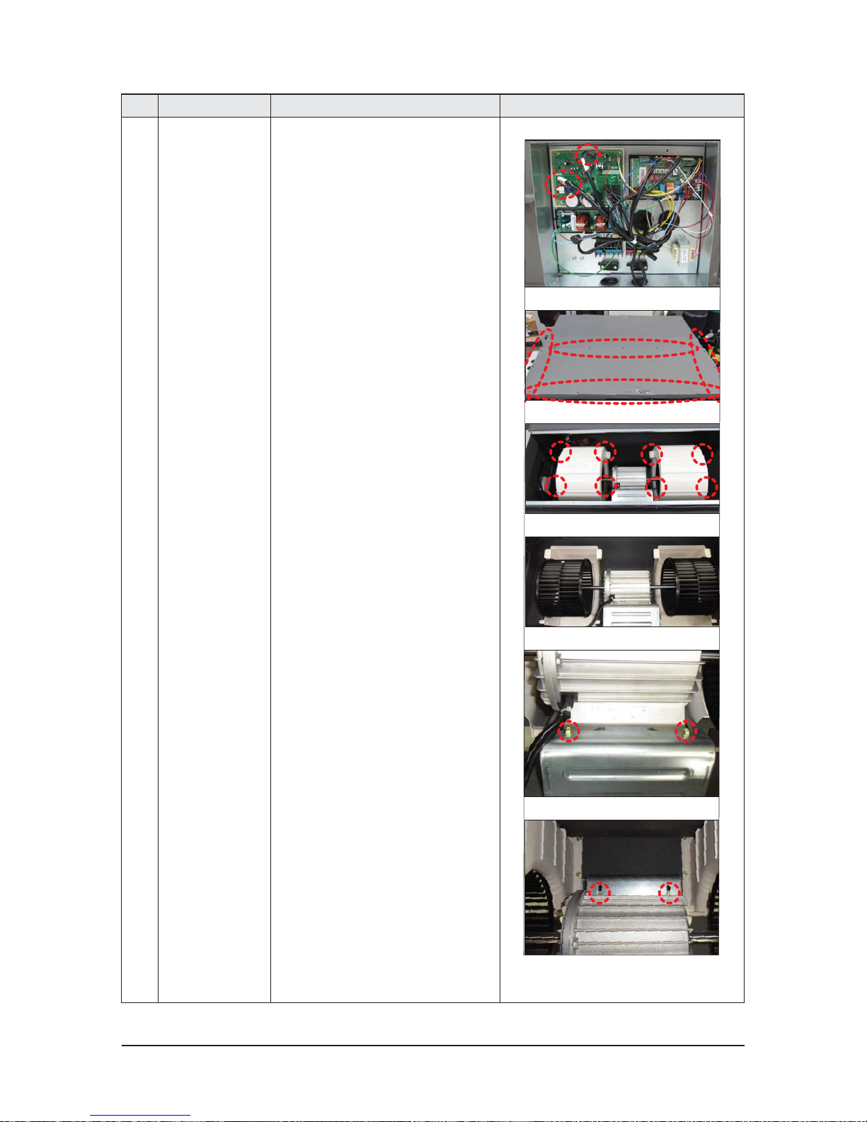
No Parts Procedure Remark
1 ASSY BLOWER 1) Loosen 17 screws of the Cabinet Top.
2) Remove the Cabinet Top.
3) Loosen 3 screws of the cover control.
4) Separate the moter connectors from assy
control in.
3-1 Indoor Unit
■ NS100HHXEH/XSA, NS125HHXEH/XSA, NS140HHXEH/XSA, NS155HHXEH/XSA
Samsung Electronics 3-3
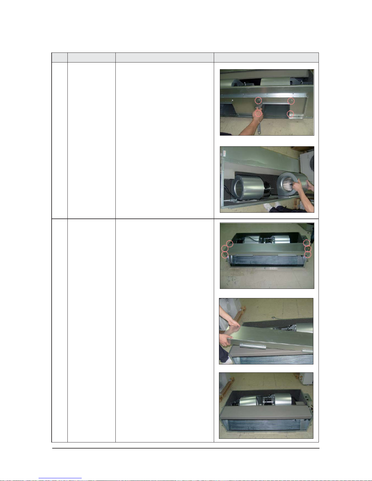
No Parts Procedure Remark
5) Loosen 8 screws from both sides of the
Cabinet Front.
6) Remove 2 assy blower parts from the
Indoor Unit.
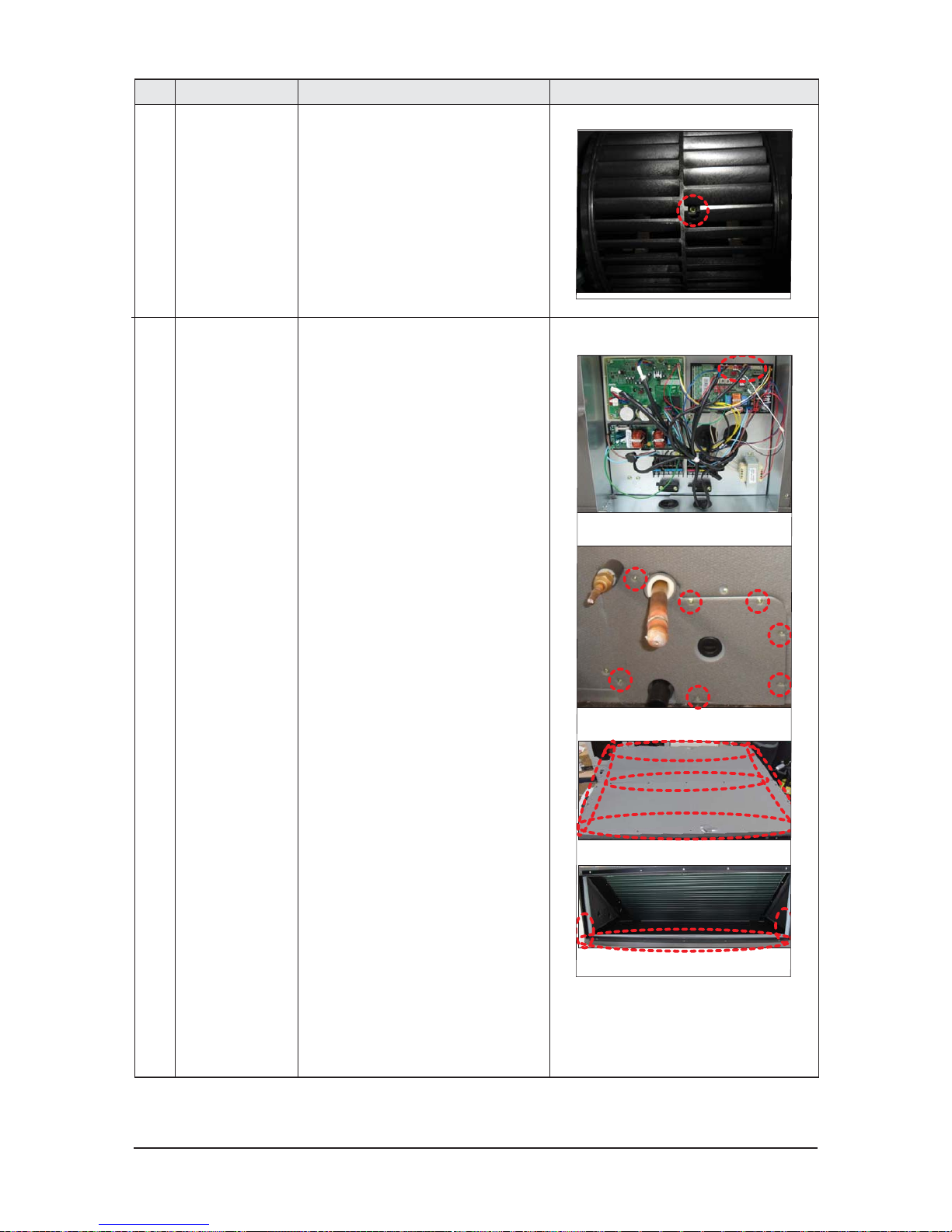
2 ASSY DRAIN PAN 1) Loosen 6 screws of the cabinet pan.
2) Remove the the cabinet pan.
3-4 Samsung Electronics
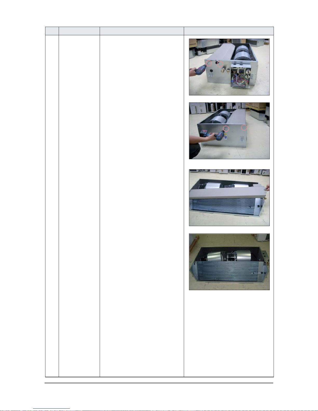
No Parts Procedure Remark
2) Loosen 2 screws of Cabinet Right.
3) Loosen 2 screws of Cabinet Left.
4) Remove the drain pan from the Indoor Unit
.
Samsung Electronics 3-5
No Parts Procedure Remark
3 ASSY EVAP 1) Loosen 2 screws of Cabinet Right.
2) Loosen 2 screws of Cabinet Left.
3) Loosen 2 screws of Cabinet Left.
4) Disassemble Sensor on the Evap Unit.
5) Remove the assy Evap unit.

3-6 Samsung Electronics
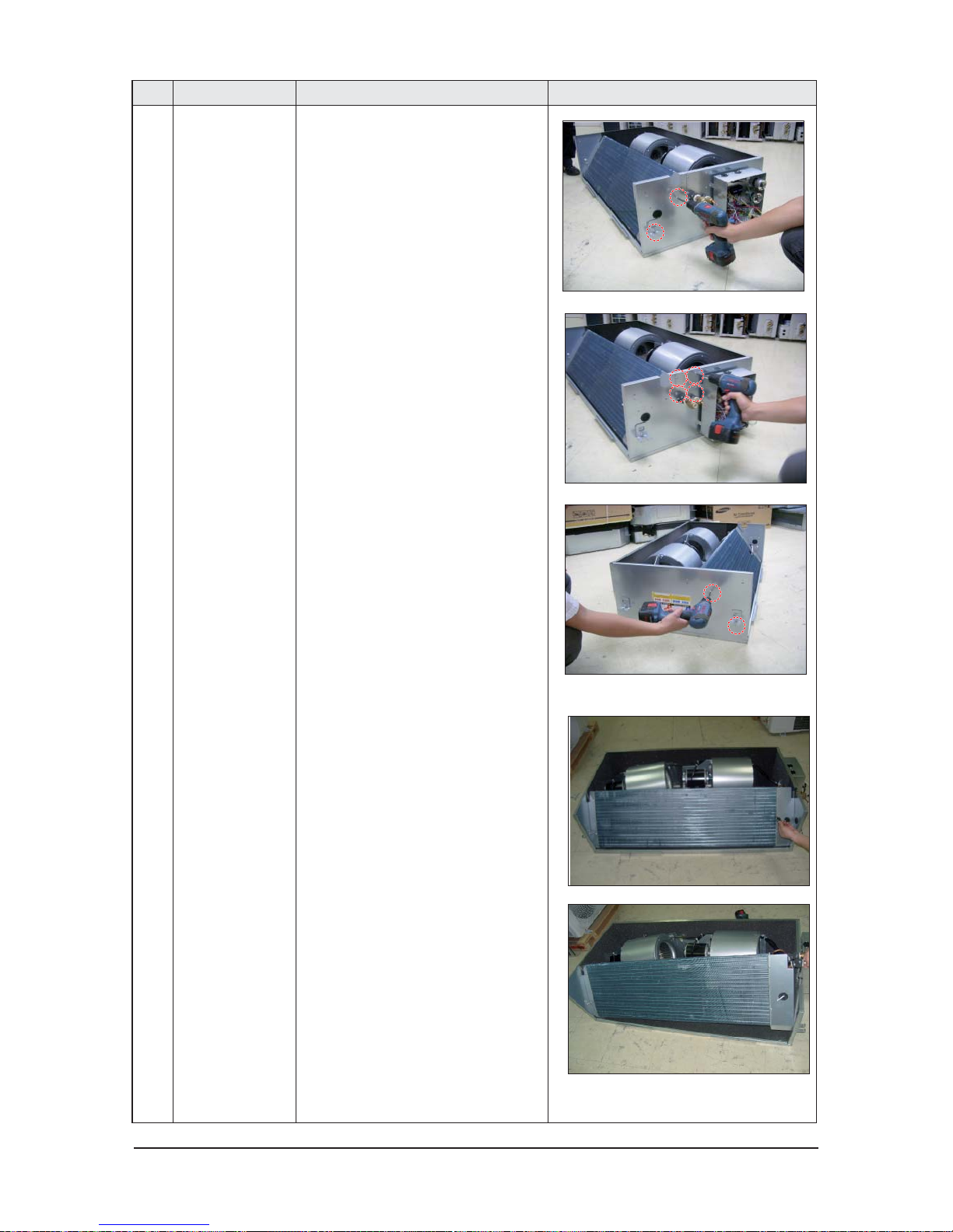
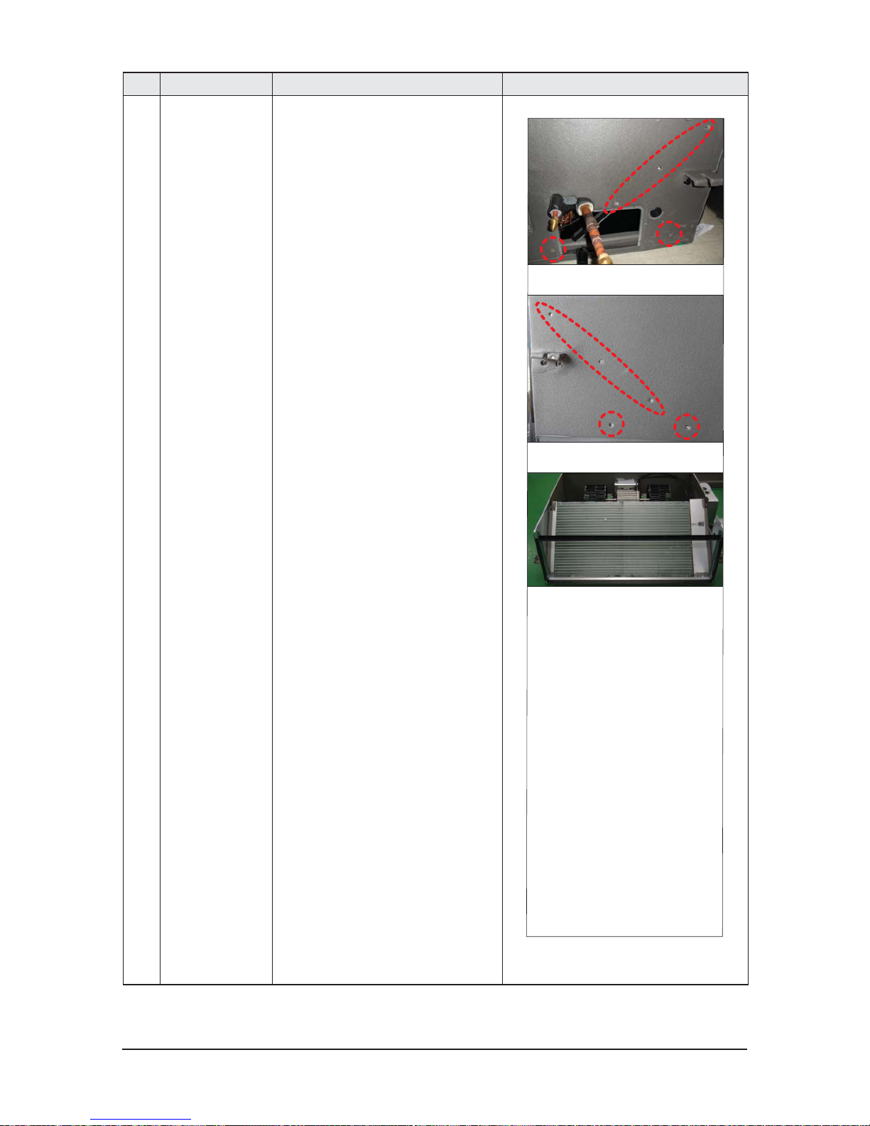
No Parts Procedure Remark
4 ASSY CONTROL IN 1) Separate the all connectors from assy con-
trol in.
2) Loosen 4 screws of Assy control in and
Remove the assy control in.
Samsung Electronics 3-7
■ NS180HHXEH/XSA
No Parts Procedure Remark
1 MOTOR
&
BLOWER
1) Detach the motor connectors from the PCB.
2) Unscew 16 screws and detach CabinetBase Blower. (Use+Screw Driver)
3) Unscrew 8 screws and detach Case-Blower.
(Use +Screw Driver)
4) Unscrew 4 bolts and separate Motor &
blower from Bracket-Motor.
(Use +Screw Driver)
3-8 Samsung Electronics
No Parts Procedure Remark
2 EVAPORATOR & DRAIN-
PAN
5) Unscrew bolt and Separate Blower from
the motor. (Use +Screw Driver)
1) Detach EEV and Sensor connectors from
the PCB. (Use +Screw Driver)
2) Unscrew 8 screws and Detach Cover-Pipe.
(Use +Screw Driver)
3) Unscrew 31 screws and detach CabinetBase Blower andCabinet-Base Drain.
(Use +Screw Driver)
Samsung Electronics 3-9
No Parts Procedure Remark
4) Unscrew 10 screws and detach Drain-Pan
from the indoor unit. (Use +Screw Driver)
5) Separate Evaporator from the indoor unit.
3-10 Samsung Electronics
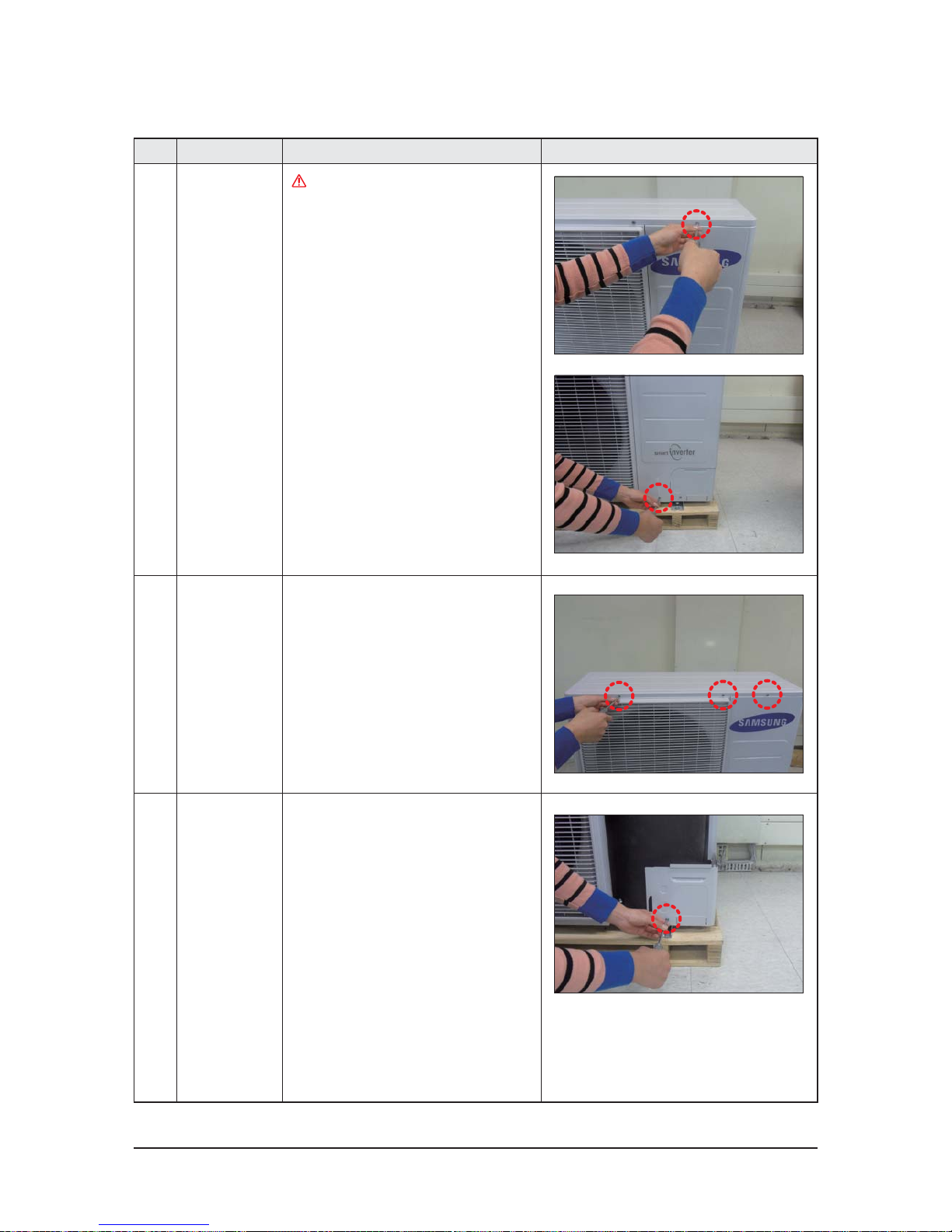
No Parts Procedure Remark
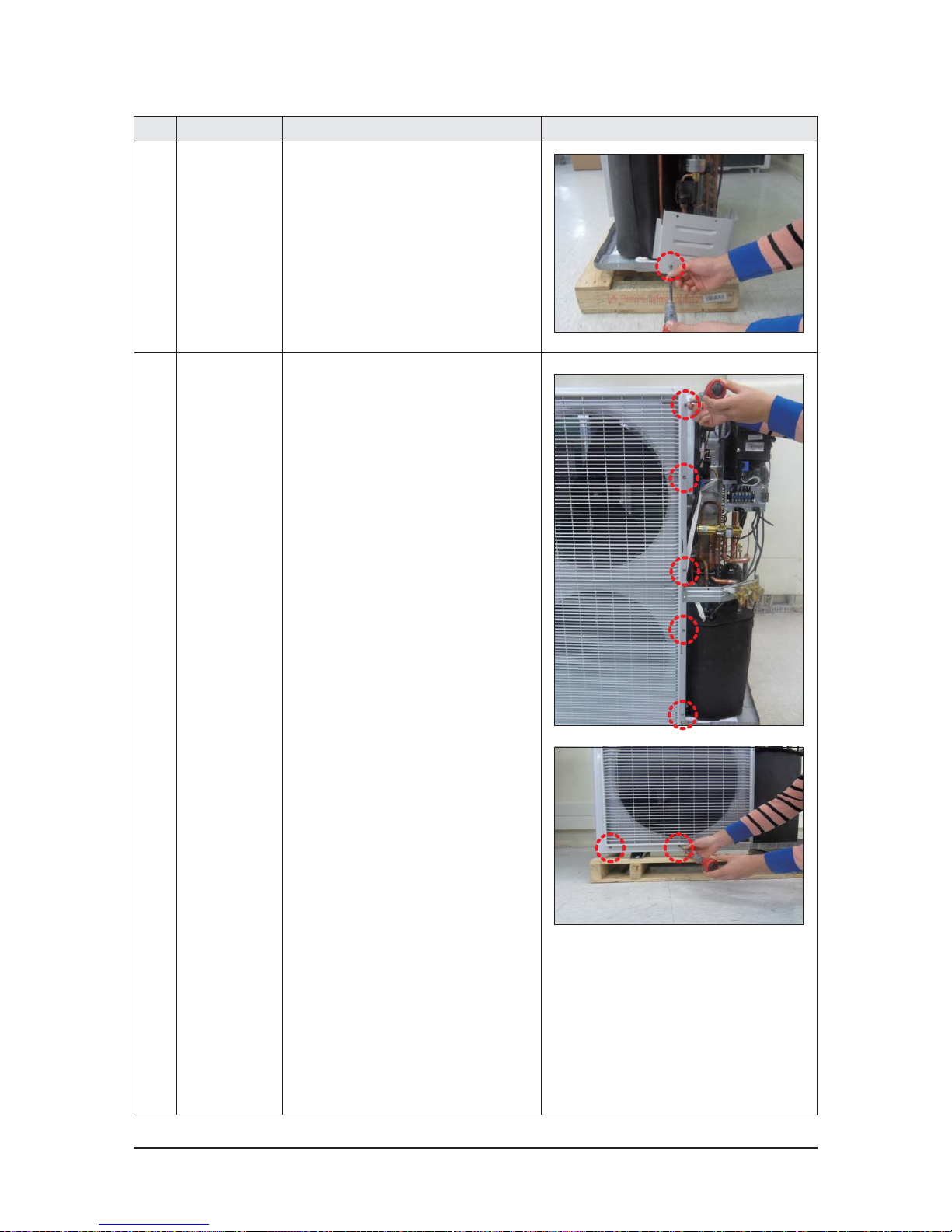
1 Cabi Front RH
You must turn off the Power before
disassembly.
1) Unscrew and remove 2 mounting screw
in the Cabinet Front RH.
(Use +Screw Driver)
2 Cabi Top 1) Unscrew and remove 9 screws
on each side of the Cabinet-Top.
(Use +Screw Driver)
3 Cabi Install Front 1) Unscrew and remove 1 screw
in the Cabinet-Install Front.
(Use +Screw Driver)
3-2 OUTDOOR UNIT

Samsung Electronics 3-11
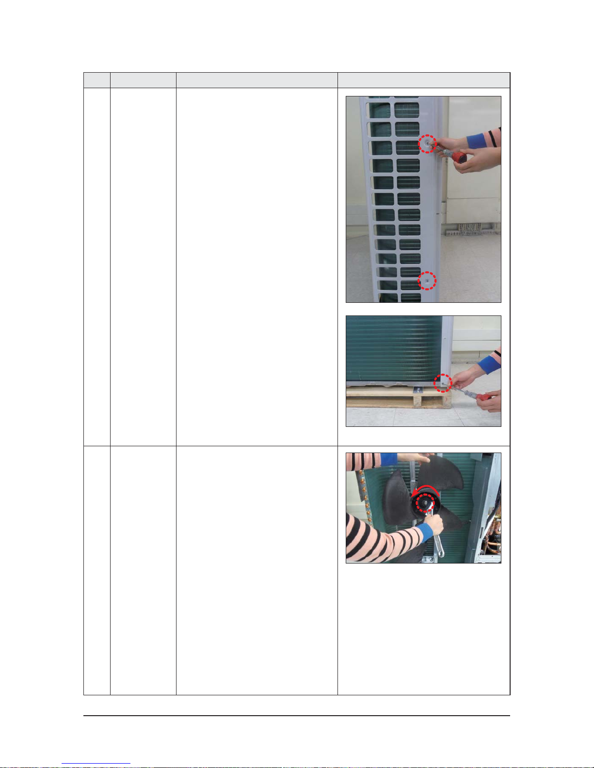
No Parts Procedure Remark
4 Guard Cond 1) Pull the sensor from Guard Cond.
2) Unscrew and remove 4 screws
in the Guard Cond.
(Use +Screw Driver)
5 Cabi Back RH 1) Pull the sensor from Cabi Back RH.
2) Unscrew and remove 4 screws
on each side of the Cabinet Back RH.
(Use +Screw Driver)
3-12 Samsung Electronics
No Parts Procedure Remark
6 Cabi Install Back 1) Unscrew and remove 1 screw
in the Cabinet-Install Back.
(Use +Screw Driver)
7 Cabi Front LF 1) Unscrew and remove 10 screws
in the Cabinet-Front LF.
(Use +Screw Driver)
Samsung Electronics 3-13
No Parts Procedure Remark
8 Fan 1) Turn 2 mounting nuts as shown in the
picture and remove it. (Use Adjustable
Wrench)
3-14 Samsung Electronics
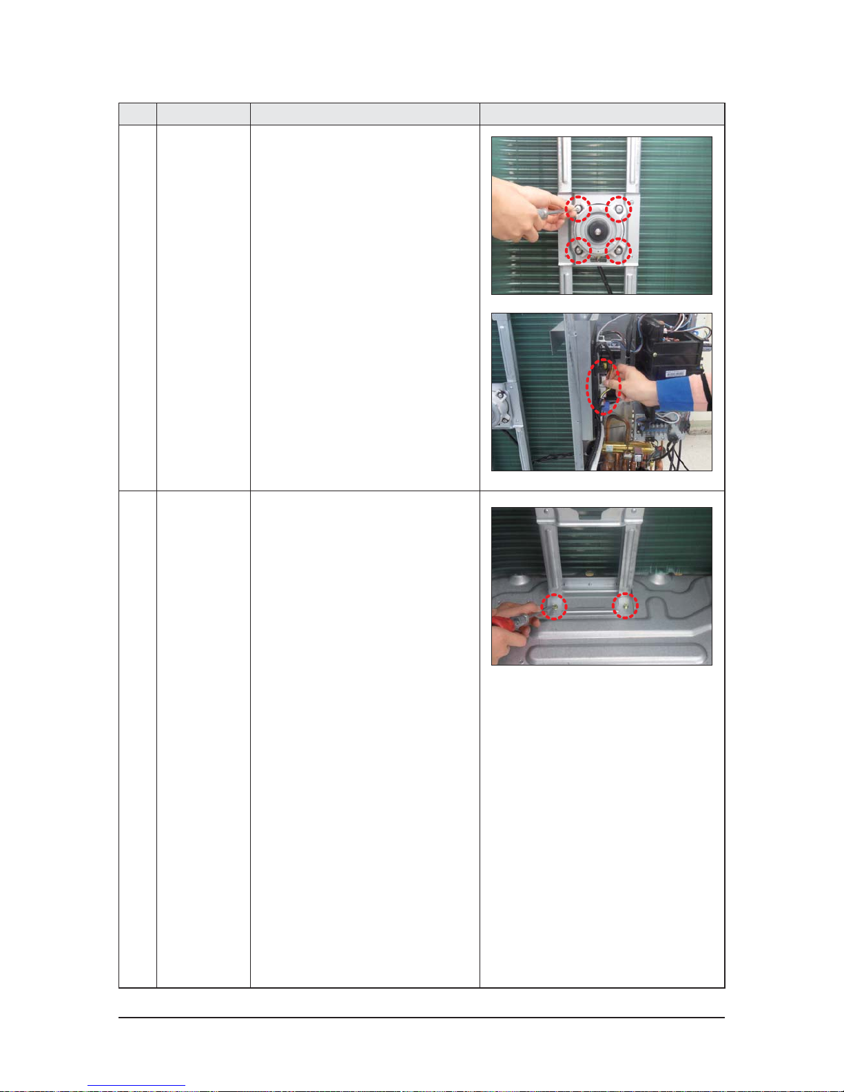
No Parts Procedure Remark
9 Motor 1) Separate the Fan Propeller.
2) Unscrew and remove the 8 Motor mounting
screws. (Use +Screw Driver)
3) Disconnect the Motor wire From
Ass'y Control Out.
10 Bracket Motor 1) Unscrew and remove 2 mounting screws
in Bracket Motor. (Use +Screw Driver)
Samsung Electronics 3-15
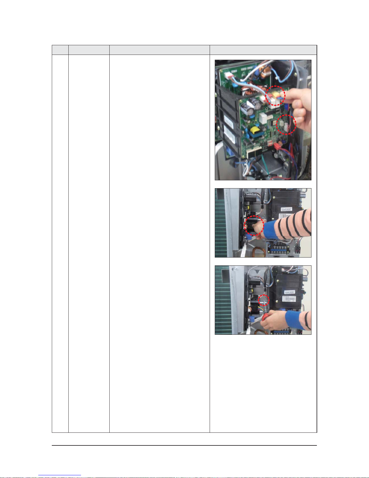
No Parts Procedure Remark
11 Control Out 1) Disconnect 4 Connecters From
Ass'y Control Out.
2) Unscrew and remove 1 mounting screw
in Control Out. (Use +Screw Driver)
3) Separate Ass'y Control Out.
3-16 Samsung Electronics
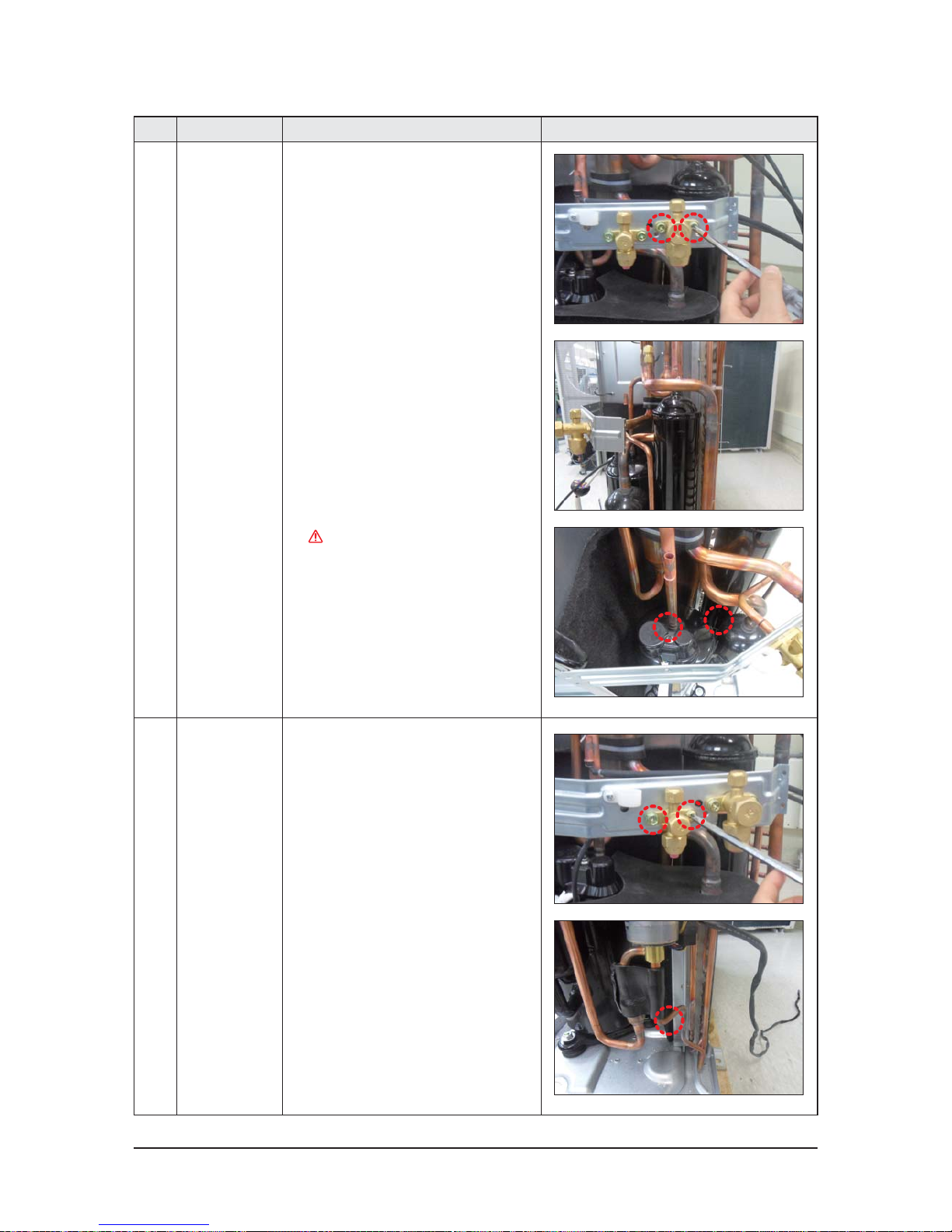
No Parts Procedure Remark
12 Ass'y 4way Valve 1) Purge the Coolant fi rst.
2) Unscrew and remove 2 mounting screws
in Service Valve. (Use +Screw Driver)
3) Separate the pipe from the Entrance/Exit
using a welder.
When removing the compressor,
Heat Exchanger, and Pipe, purge the
Coolant inside the Compressor
completely and remove the pipe
with a welding fl ame.
13 Ass;y EEV Valve 1) Unscrew and remove 2 mounting screws
in Service Valve. (Use +Screw Driver)
2) Separate the pipe from the Entrance/Exit
using a welder.
Samsung Electronics 3-17
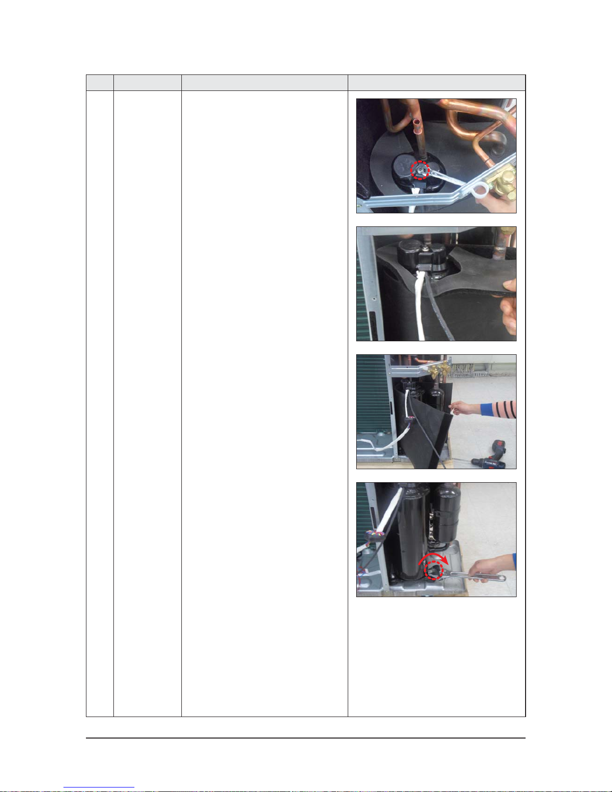
No Parts Procedure Remark
14 Compressor 1) Unscrew and remove 1 mounting nut
in Cover Terminal. (Use Adjustable Wrench)
2) Separate the Compressor Felt Sound.
3) As shown in the picture, unscrew and
remove 3 mounting screws from the
bottom. (Use Adjustable Wrench)
 Loading...