

Samsung NS100SSXEA, NS100SDXEA, NS090SSXEX, NS100SSXEX, NS125SDXEA Service Manual
...
Refer to the service manual in the GSPN(see the rear cover) for the more information.
AIR CONDITIONER CONTENTS
SYSTEM AIR CONDITIONER
Model : NS100SSXEA
NS090SDXEA
NS090SSXEA
NS090SSXEX
NS100SSXEX
NS100SDXEA
NS125SDXEA
NS140SDXEA
RC100SHXEA
RC090SHXEA
RC090DHXEA
RC100DHXEA
RC100DHXGA
RC125DHXEB
RC125DHXGA
RC140DHXEB
RC140DHXGA
INDOOR UNIT OUTDOOR UNIT
1. Precautions
2. Product Specifications
3. Disassembly and Reassembly
4. Troubleshooting
5. Exploded Views and Parts List
6. PCB Diagram
7. Wiring Diagram
8. Schematic Diagram
9. Reference Sheet
NS090SDXEA, NS100SSXEA
NS090SSXEA, NS090SSXEX, NS100SSXEX
NS100SDXEA
NS125SDXEA
NS140SDXEA
RC090DHXEA
RC090SHXEA
RC100SHXEA
RC100DHXEA
RC100DHXGA
RC125DHXEB
RC125DHXGA
RC140DHXEB
RC140DHXGA
NS100SSXEA_E_33623A(1)_co.indd 1 2011-04-08 �� 10:52:44

Contents
11. Precautions
.... ... .... ... .... .... ... .... ... .... ... .... ... .... ... .... ... .... ... .... .... ... .... ... .... ... .... ... .... ... .... ... .... ... .... .... ... .... .
1-1
1-1 Precautions for the Service
... ... .... ... .... ... .... .... ... .... ... .... ... .... ... .... ... .... ... .... ... .... .... ... .... ... .... ... .... ... .... .
1-1
1-2 Precautions related to static electricity and PL
... ... .... .... ... .... ... .... ... .... ... .... ... .... ... .... ... .... .... ... .... ..
1-1
1-3 Precautions related to product safety
.. .... ... .... ... .... ... .... ... .... ... .... ... .... .... ... .... ... .... ... .... ... .... ... .... ... .
1-2
1-4 Other precautions
. ... .... ... .... .... ... .... ... .... ... .... ... .... ... .... ... .... ... .... .... ... .... ... .... ... .... ... .... ... .... ... .... ... .... .... .
1-2
12. Product Specifications
.... ... .... ... .... ... .... ... .... .... ... .... ... .... ... .... ... .... ... .... ... .... ... .... .... ... .... ... .... ... .... .
2-1
2-1 The Feature of Product
.... ... .... ... .... ... .... ... .... ... .... .... ... .... ... .... ... .... ... .... ... .... ... .... ... .... .... ... .... ... .... ... ....
2-1
2-2 Product Specifications
.... ... .... ... .... ... .... ... .... ... .... ... .... ... .... .... ... .... ... .... ... .... ... .... ... .... ... .... ... .... .... ... .... .
2-2
2-3 Specifications of optional items
... .... ... .... ... .... .... ... .... ... .... ... .... ... .... ... .... ... .... ... .... .... ... .... ... .... ... .... ...
2-6
2-3-1 Accessories
.... ... .... ... .... ... .... ... .... ... .... ... .... ... .... .... ... .... ... .... ... .... ... .... ... .... ... .... ... .... .... ... .... ... .... ...
2-6
13. Disassembly and Reassembly
. ... .... ... .... ... .... ... .... ... .... .... ... .... ... .... ... .... ... .... ... .... ... .... ... .... .... ..
3-1
3-1 Indoor Unit
.. .... ... .... ... .... ... .... ... .... .... ... .... ... .... ... .... ... .... ... .... ... .... ... .... .... ... .... ... .... ... .... ... .... ... .... ... .... ... .
3-2
3-2 Outdoor Unit
.. ... .... ... .... ... .... ... .... .... ... .... ... .... ... .... ... .... ... .... ... .... ... .... .... ... .... ... .... ... .... ... .... ... .... ... .... ... .
3-7
14. Troubleshooting
... ... .... ... .... ... .... ... .... .... ... .... ... .... ... .... ... .... ... .... ... .... ... .... .... ... .... ... .... ... .... ... .... ... .... .
4-1
4-1 Indoor Display Error and Check Method
... ... .... ... .... ... .... ... .... ... .... .... ... .... ... .... ... .... ... .... ... .... ... .... .
4-1
4-1-1 Wired Remocon Error Display(COM2)
... .... ... .... ... .... .... ... .... ... .... ... .... ... .... ... .... ... .... ... .... .... ..
4-2
4-2 Outdoor LED Error Display and Check Method
.. .... ... .... ... .... ... .... .... ... .... ... .... ... .... ... .... ... .... ... .... ..
4-3
4-3 Setting Option Setup Method
... ... .... ... .... ... .... ... .... .... ... .... ... .... ... .... ... .... ... .... ... .... ... .... .... ... .... ... .... ..
4-4
4-3-1 Type A(Setting Option)
.. .... ... .... .... ... .... ... .... ... .... ... .... ... .... ... .... ... .... .... ... .... ... .... ... .... ... .... ... ....
4-4
4-3-2 Type B(Setting Option Setup Method)
. ... .... ... .... ... .... .... ... .... ... .... ... .... ... .... ... .... ... .... ... .... ....
4-6
4-3-3 Option code for each model
... .... .... ... .... ... .... ... .... ... .... ... .... ... .... ... .... .... ... .... ... .... ... .... ... .... ... .
4-16
4-4 Items to be checked first
.. .... ... .... ... .... .... ... .... ... .... ... .... ... .... ... .... ... .... ... .... .... ... .... ... .... ... .... ... .... ... .... .
4-17
4-5 Fault Diagnosis by Symptom
.. .... ... .... ... .... ... .... .... ... .... ... .... ... .... ... .... ... .... ... .... ... .... .... ... .... ... .... ... .... .
4-18
4-5-1 No Power(completely dead) - Initial diagnosis
... ... .... ... .... ... .... .... ... .... ... .... ... .... ... .... ... .... ..
4-18
4-5-2 The Outdoor unit Power Supply error
... ... .... ... .... .... ... .... ... .... ... .... ... .... ... .... ... .... ... .... .... ... ...
4-19
4-5-3 The Outdoor unit Fan error
... ... .... ... .... ... .... ... .... ... .... ... .... .... ... .... ... .... ... .... ... .... ... .... ... .... ... ....
4-20
4-5-4 Total current trip error
... ... .... ... .... ... .... ... .... .... ... .... ... .... ... .... ... .... ... .... ... .... ... .... .... ... .... ... .... ... ..
4-21
4-5-5 In case of heating at the cooling mode or cooling at the heating mode
.... ... .... ... .... ..
4-22
4-5-6 Outdoor temperature sensor error
.... ... .... ... .... ... .... ... .... .... ... .... ... .... ... .... ... .... ... .... ... .... ... ....
4-24
4-5-7 Discharge temperature sensor error
.. .... ... .... ... .... ... .... ... .... ... .... .... ... .... ... .... ... .... ... .... ... .... ..
4-25
4-5-8 Coil temperature sensor error
... .... ... .... ... .... .... ... .... ... .... ... .... ... .... ... .... ... .... ... .... .... ... .... ... .... ..
4-26
4-5-9 Fan error
... .... ... .... ... .... ... .... ... .... ... .... ... .... ... .... .... ... .... ... .... ... .... ... .... ... .... ... .... ... .... .... ... .... ... .... ... .
4-27
4-5-10 DC-Link voltage sensor error
.. .... .... ... .... ... .... ... .... ... .... ... .... ... .... ... .... .... ... .... ... .... ... .... ... .... ..
4-28
4-5-11 O.C.(Over Current) error
... ... .... ... .... ... .... ... .... .... ... .... ... .... ... .... ... .... ... .... ... .... ... .... .... ... .... ... ....
4-29
NS090SDXEA_E_SM_33623A(1)_1.indd 1 2011-04-08 �� 10:54:25

Contents
4-5-12 Communication error
. ... .... ... .... ... .... ... .... .... ... .... ... .... ... .... ... .... ... .... ... .... ... .... .... ... .... ... .... ... ...
4-30
4-5-13 Compressor start error
.... ... .... ... .... ... .... ... .... ... .... ... .... ... .... .... ... .... ... .... ... .... ... .... ... .... ... .... ... ..
4-31
4-5-14 Compressor lock error
... ... .... .... ... .... ... .... ... .... ... .... ... .... ... .... ... .... .... ... .... ... .... ... .... ... .... ... .... ...
4-32
4-5-15 DC Link Over voltage/ Low voltage error
... .... ... .... ... .... .... ... .... ... .... ... .... ... .... ... .... ... .... ... ..
4-33
4-6 PCB Inspection Method
.... ... .... .... ... .... ... .... ... .... ... .... ... .... ... .... ... .... .... ... .... ... .... ... .... ... .... ... .... ... .... ... ..
4-34
4-6-1 Pre-inspection Notices
... .... ... .... ... .... ... .... ... .... .... ... .... ... .... ... .... ... .... ... .... ... .... ... .... .... ... .... ... .... .
4-34
4-6-2 Inspection Procedure
... ... .... ... .... ... .... ... .... ... .... ... .... ... .... .... ... .... ... .... ... .... ... .... ... .... ... .... ... .... ...
4-34
4-6-3 Indoor Detailed Inspection Procedure
.. .... ... .... ... .... ... .... .... ... .... ... .... ... .... ... .... ... .... ... .... ... ...
4-34
4-6-4 Outdoor Detailed Inspection Procedure
.. ... .... ... .... ... .... ... .... .... ... .... ... .... ... .... ... .... ... .... ... ...
4-35
4-7 Main Part Inspection Method
.. .... ... .... ... .... ... .... ... .... ... .... .... ... .... ... .... ... .... ... .... ... .... ... .... ... .... .... ... ....
4-36
15. Exploded Views and Parts List
.. .... ... .... ... .... ... .... ... .... ... .... ... .... ... .... .... ... .... ... .... ... .... ... .... ... ...
5-1
5-1 Indoor Unit
.... ... .... ... .... ... .... ... .... .... ... .... ... .... ... .... ... .... ... .... ... .... ... .... .... ... .... ... .... ... .... ... .... ... .... ... .... ... ...
5-1
5-2 Outdoor Unit
. .... ... .... ... .... ... .... ... .... .... ... .... ... .... ... .... ... .... ... .... ... .... ... .... .... ... .... ... .... ... .... ... .... ... .... ... .... .
5-7
5-3 Ass'y Control Out
.. ... .... ... .... .... ... .... ... .... ... .... ... .... ... .... ... .... ... .... .... ... .... ... .... ... .... ... .... ... .... ... .... ... .... ....
5-11
16. PCB Diagram
.... ... .... ... .... ... .... .... ... .... ... .... ... .... ... .... ... .... ... .... ... .... .... ... .... ... .... ... .... ... .... ... .... ... .... ... .... ..
6-1
6-1 PCB Diagram
.. .... ... .... ... .... ... .... ... .... ... .... ... .... .... ... .... ... .... ... .... ... .... ... .... ... .... ... .... .... ... .... ... .... ... .... ... .... .
6-1
6-1-1 Indoor Unit
.. ... .... ... .... ... .... ... .... ... .... .... ... .... ... .... ... .... ... .... ... .... ... .... ... .... .... ... .... ... .... ... .... ... .... ... .
6-1
6-1-2 Outdoor Unit PCB
.. .... ... .... .... ... .... ... .... ... .... ... .... ... .... ... .... ... .... .... ... .... ... .... ... .... ... .... ... .... ... .... ...
6-3
17. Wiring Diagram
... ... .... ... .... .... ... .... ... .... ... .... ... .... ... .... ... .... ... .... .... ... .... ... .... ... .... ... .... ... .... ... .... ... .... ...
7-1
6-1 Indoor Unit
.... ... .... ... .... ... .... ... .... .... ... .... ... .... ... .... ... .... ... .... ... .... ... .... .... ... .... ... .... ... .... ... .... ... .... ... .... ... ...
7-1
6-1 Outdoor Unit
. .... ... .... ... .... ... .... ... .... .... ... .... ... .... ... .... ... .... ... .... ... .... ... .... .... ... .... ... .... ... .... ... .... ... .... ... .... .
7-2
18. Schematic Diagram
.... ... .... ... .... .... ... .... ... .... ... .... ... .... ... .... ... .... ... .... .... ... .... ... .... ... .... ... .... ... .... ... .... .
8-1
8-1 Indoor Unit
.... ... .... ... .... ... .... ... .... .... ... .... ... .... ... .... ... .... ... .... ... .... ... .... .... ... .... ... .... ... .... ... .... ... .... ... .... ... ...
8-1
8-1-1 MAIN PCB
.... .... ... .... ... .... ... .... ... .... ... .... ... .... ... .... .... ... .... ... .... ... .... ... .... ... .... ... .... ... .... .... ... .... ... .... .
8-1
8-1-2 Outdoor Unit PCB
.. .... ... .... .... ... .... ... .... ... .... ... .... ... .... ... .... ... .... .... ... .... ... .... ... .... ... .... ... .... ... .... ...
8-2
1
9. Reference Sheet
.... ... .... ... .... ... .... ... .... .... ... .... ... .... ... .... ... .... ... .... ... .... ... .... .... ... .... ... .... ... .... ... .... ... .... ..
9-1
9-1 Index for Model Name
... .... ... .... .... ... .... ... .... ... .... ... .... ... .... ... .... ... .... .... ... .... ... .... ... .... ... .... ... .... ... .... ... ..
9-1
9-2 Refrigerating Cycle Diagram
.. .... ... .... ... .... ... .... .... ... .... ... .... ... .... ... .... ... .... ... .... ... .... .... ... .... ... .... ... .... ...
9-3
9-3 Pressure Graph
.... .... ... .... ... .... ... .... ... .... ... .... ... .... ... .... .... ... .... ... .... ... .... ... .... ... .... ... .... ... .... .... ... .... ... .... ...
9-4
NS090SDXEA_E_SM_33623A(1)_1.indd 2 2011-04-08 �� 10:54:25

Samsung Electronics 1-1
1. Precautions
1-1 Precautions for the Service
Use the standard parts when replacing the electric parts.
– Confirm the model name, rated voltage, rated current of the electric parts.
When repairing the equipment, connection of the harness parts must be firm and solid.
– A loose connection may cause noise or other malfunction.
When assembling and disassembling the equipment while it is laid down, lay it on soft cloth.
– Otherwise it may scratch the back of the exterior of the product.
Remove dust or dirt completely from the housing block, wiring block and service parts during repair.
– This helps prevent the danger of fire caused by tracking or short circuit.
Fasten the valve caps of service valves and charging valves of outdoor unit as much as possible using adjustable wrenches.
Check the status of the components’ assembly after repair service.
– The status must be the same as before the repair service.
1-2 Precautions related to static electricity and PL
The PCB power supply block is susceptible to static electricity. Therefore, care must be taken during repair or measuring
while the power is on.
– Wear insulation gloves for PCB repair or measuring.
Check whether the installation location is at least two meters away from other electronic products such as TV, video, or
audio.
– Otherwise, the video quality might be degraded or noise might be generated.
Do not let end users repair the products themselves.
– Unauthorized disassembly might cause electric shock or fire.
NS090SDXEA_E_SM_33623A(1)_1.indd 1 2011-04-08 �� 10:54:26

1-2 Samsung Electronics
1-3 Precautions related to product safety
Do not pull the power cord and do not touch the power plug or aux power switch with wet hands.
– It might cause electric shock or fire.
A damaged power line or power plug must be replaced to prevent danger.
Do not bend the power cable with excessive force, and do not place a heavy weight on the case as it might damage the
cable.
– It might cause electric shock or fire.
Do not use multiple electric outlets.
– This might cause electric shock or fire.
Connect the ground terminal when necessary.
– You must connect the ground terminal if you determine that there is a danger of electric leakage due to moisture or water.
Unplug the power cable or turn off the auxiliary power switch for electric part replacement and repair service.
– Otherwise it might cause electric shock.
Instruct end users to separate the batteries from the remote controllers and store them separately when the product is not
used for long time.
– Otherwise leakage from the dry cell may cause problems with the remote controller.
1-4 Other precautions
The pipes should have no leaks during installation, and the compressor must be stopped before removing connecting
pipes for pump down work. Operating the compressor while the service valve is open and coolant pipe is not properly
connected may cause explosion or injury due to abnormal high pressure created inside the coolant cycle as the air can be
absorbed through the pipe.
Pump Down work procedure (When uninstalling the product)
– Turn on the air conditioner, select cooling operation, and run the compressor for more than three minutes.
– Release the high pressure and low pressure valve caps.
– Close the high pressure valve completely using an L-wrench
– After about two minutes, close the low pressure valve completely.
– Stop running the air conditioner.
– Separate the connecting pipe.
NS090SDXEA_E_SM_33623A(1)_1.indd 2 2011-04-08 �� 10:54:26

Samsung Electronics 2-1
2. Product Specifications
2-1 The Feature of Product
Built-in Cassette Type
After installed, the air conditioner can be harmonized with a room interior.
High Performance & Energy Saving
With the advanced BLDC inverter technology, it makes a room cool with highly energy saving and arises the efficiency of
air conditioner.
Long Piping(Length & Height)
It can give the benefit to the installers and aries the reliability of the air conditioner.
Long Ambient Operation(In Low Temperature)
It can arise the reliability and the capacity of the air conditioner, especially operated in low temperature.
Eco-friendly Product(Lead-Free, RoHS, WEEE)
NS090SDXEA_E_SM_33623A(1)_1.indd 1 2011-04-08 �� 10:54:26
2-2 Samsung Electronics
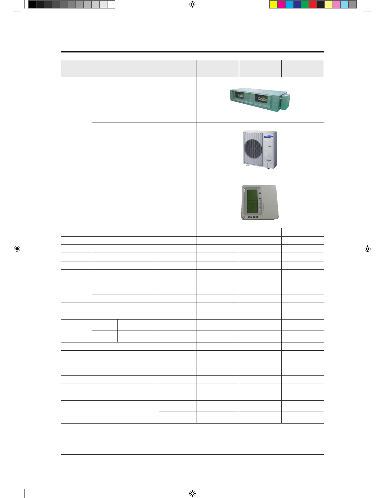
ITEM
NS090SDXEA
/RC090DHXEA
NS090SSXEA
NS090SSXEX
/RC090SHXEA
NS100SSXEA
NS100SSXEX
/RC100SHXEA
IMAGE
Indoor Unit
Outdoor Unit
Remote Controller
Power Product 1Φ, 220~240V/50Hz 1Φ, 220~240V/50Hz 1Φ, 220~240V/50Hz
Indoor L x H x D mm 1150x480x320 1150x480x260 1150x480x260
Outdoor L x H x D mm 940x330x998 940x330x998 940x330x998
Indoor Product kg(Net) 39.0 34.0 34.0
Outdoor Product kg(Net) 72.0 72.0 72.0
Capacity
Cooling(STD) W 9000 9000 10000
Heating(STD) W 10000 9500 11200
Power
Consumption
Cooling(STD) W 2800 3200 3560
Heating(STD) W 2770 2780 3720
Operation
current
Cooling(STD) A 13.0 14.0 16.0
Heating(STD) A 12.5 13.0 15.0
Noise
(Cooling/
Heating)
Indoor unit
In case of strongest air
blow
A 48/49 49/50 49/50
Outdoor unit
In case of strongest air
blow
A 58/60 59/62 59/62
Refrigerant g 3000 2500 2500
Connecting Pipe
Liquid mm 9.52 9.52 9.52
Gas mm 15.88 15.88 15.88
Additional Refrigernat g/m 50 50 50
Standard m 5 5 5
Extension length(Total) m 50 50 50
Extension length(Elevation) m 30 30 30
Option Code
Product Option
011044-156299275A64-350000
011044-156293275A64-370000
011044-156293276470-370000
Installation Option
020000-100000-
200000-300000
020000-100000-
200000-300000
020000-100000-
200000-300000
2-2 Product Specifications
NS090SDXEA_E_SM_33623A(1)_1.indd 2 2011-04-08 �� 10:54:26
Samsung Electronics 2-3
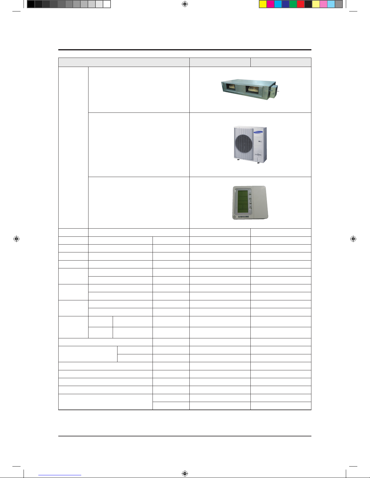
ITEM NS100SDXEA/RC100DHXEA NS100SDXEA/RC100DHXGA
IMAGE
Indoor Unit
Outdoor Unit
Remote Controller
Power Product 1Φ, 220~240V/50Hz 3Φ, 380~415V/50Hz
Indoor L x H x D mm 1200x650x360 1200x650x360
Outdoor L x H x D mm 940x330x998 940x330x998
Indoor Product kg(Net) 55.0 55.0
Outdoor Product kg(Net) 72.0 81.0
Capacity
Cooling(STD) Btu or W 10000 10000
Heating(STD) Btu or W 11200 11200
Power
Consumption
Cooling(STD) W 3120 3120
Heating(STD) W 3100 3100
Operation
current
Cooling(STD) A 13.8 5.0
Heating(STD) A 13.5 5.0
Noise
(Cooling/
Heating)
Indoor unit
In case of strongest air
blow
dB 49/50 49/50
Outdoor unit
In case of strongest air
blow
dB 59/63 59/63
Refrigerant g 3000 3100
Connecting Pipe
Liquid mm 9.52 9.52
Gas mm 15.88 15.88
Additional Refrigernat g/m 50 50
Standard m 5 5
Extension length(Total) m 50 50
Extension length(Elevation) m 30 30
Option Code
Product Option 011044-1560E8-276470-370000 011044-1560E8-276470-370000
Installation Option 020000-100000-200000-300000 020000-100000-200000-300000
Product Specifications (cont.)
NS090SDXEA_E_SM_33623A(1)_1.indd 3 2011-04-08 �� 10:54:27
2-4 Samsung Electronics
Product Specifications (cont.)
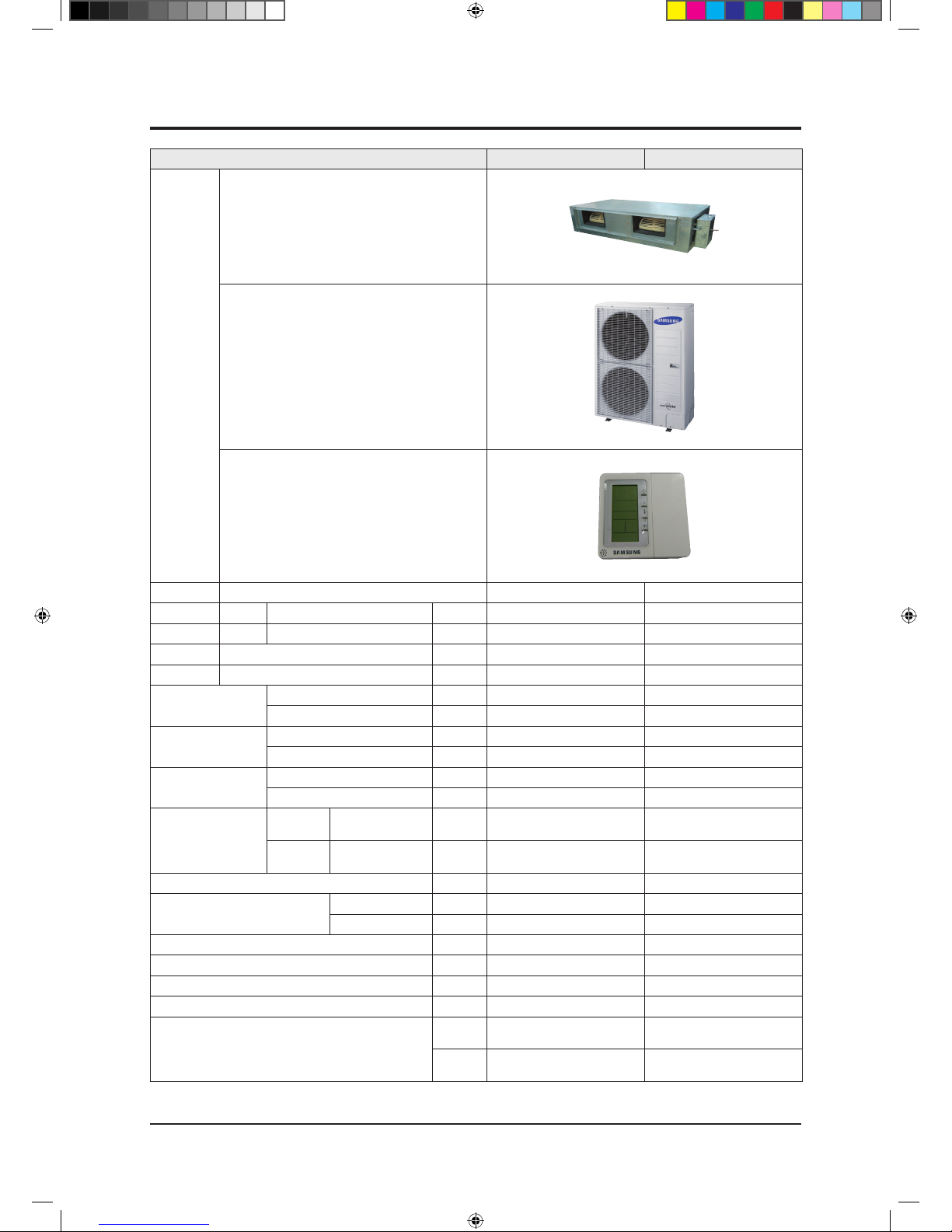
ITEM NS125SDXEA/RC125DHXEB NS125SDXEA/RC125DHXGA
IMAGE
Indoor Unit
Outdoor Unit
Remote Controller
Power Product 1Φ, 220~240V/50Hz 3Φ, 380~415V/50Hz
Indoor unit Product L x H x D mm 1200x650x360 1200x650x360
Outdoor unit Product L x H x D mm 940x330x1210 940x330x1210
Indoor unit Product kg(Net) 55.0 55.0
Outdoor unit Product kg(Net) 88.0 91.0
Capacity
Cooling(STD) Btu or W 12500 12500
Heating(STD) Btu or W 14000 14000
Power consumption
Cooling(STD) W 3890 3890
Heating(STD) W 3880 3880
Operation current
Cooling(STD) A 17.8 6.0
Heating(STD) A 17.8 6.0
Noise
(Cooling/Heating)
Indoor
unit
In case of strongest
air blow
dB 50/51 50/51
Outdoor
unit
In case of strongest
air blow
dB 59/61 59/61
Refrigerant g 2900 2900
Connecting Pipe
Liquid mm 9.52 9.52
Gas mm 15.88 15.88
Additional Refrigerant(g/m) g/m 50 50
Standard m 5 5
Extension length(Total) m 75 75
Extension length(Elevation) m 30 30
Option Code
Product
Option
011044-1570F8-277D8C-370000 011044-1570F8-277D8C-370000
Installation
Option
020000-100000-200000-300000 020000-100000-200000-300000
NS090SDXEA_E_SM_33623A(1)_1.indd 4 2011-04-08 �� 10:54:29

Samsung Electronics 2-5
ITEM NS140SDXEA/RC140DHXEB NS140SDXEA/RC140DHXGA
IMAGE
Indoor Unit
Outdoor Unit
Remote Controller
Power Product 1Φ, 220~240V/50Hz 3Φ, 380~415V/50Hz
Indoor unit Product L x H x D mm 1200x650x360 1200x650x360
Outdoor unit Product L x H x D mm 940x330x1210 940x330x1210
Indoor unit Product kg(Net) 55.0 55.0
Outdoor unit Product kg(Net) 88.0 91.0
Capacity
Cooling(STD) Btu or W 14000 14000
Heating(STD) Btu or W 16000 16000
Power consumption
Cooling(STD) W 4650 4650
Heating(STD) W 4430 4430
Operation current
Cooling(STD) A 21.3 7.2
Heating(STD) A 20.3 6.9
Noise
(Cooling/Heating)
Indoor
unit
In case of strongest
air blow
dB 50/51 50/51
Outdoor
unit
In case of strongest
air blow
dB 60/62 60/62
Refrigerant g 3400 3400
Connecting Pipe
Liquid mm 9.52 9.52
Gas mm 15.88 15.88
Additional Refrigerant(g/m) g/m 50 50
Standard m 5 5
Extension length(Total) m 75 75
Extension length(Elevation) m 30 30
Option Code
Product
Option
011044-167208-278CA0-370000 011044-167208-278CA0-370000
Installation
Option
020000-100000-200000-300000 020000-100000-200000-300000
Product Specifications (cont.)
NS090SDXEA_E_SM_33623A(1)_1.indd 5 2011-04-08 �� 10:54:31
2-6 Samsung Electronics
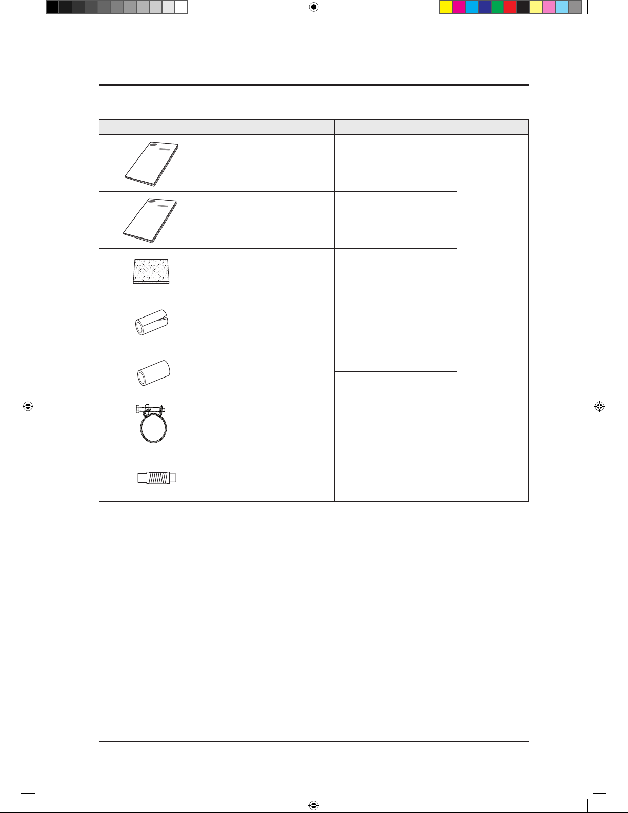
Item Description Code No. Q’ty Remark
User’s manual DB98-28944A 1
Essential Offer
Installation manual DB98-28943A 5
Insulation
DB62-03439J 1
DB62-03439H 1
Insulation Drain In DB62-03440H 1
Insulation Install Inlet
DB72-00143E 1
DB72-00143G 1
Ass'y Holder Drain Pipe DB90-02064A 1
Ass'y Drain Hose Joint DB94-00758A 1
2-3 Specifications of optional items
2-3-1 Accessories
NS090SDXEA_E_SM_33623A(1)_1.indd 6 2011-04-08 �� 10:54:32
Samsung Electronics 2-7
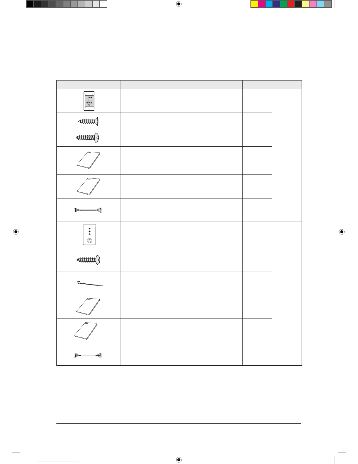
Product Specifications
Item Descriptions Code-No. Q'TY Remark
Receiver & display unit
DB93-00449A
(MRK-B00)
1
Concealed type
STS 2S-2x10 Tapped Screw - 4
2S-4x12 Tapped Screw - 2
User’s manual DB98-05160A 1
Installation manual DB98-05186A 1
Wire kit
DB39-00223A
(MRW-10A)
1
Receiver & display unit
DB93-01066A
(MRK-A00)
1
Standard type
M4x12 Tapped Screw - 7
Cable-tie - 2
User’s manual DB98-04184A 1
Installation manual DB98-04189A 1
Wire kit
DB39-00223A
(MRW-10A)
1
Accessories (cont.)
■ Receiver & display unit & Wire kit
NS090SDXEA_E_SM_33623A(1)_1.indd 7 2011-04-08 �� 10:54:33
2-8 Samsung Electronics
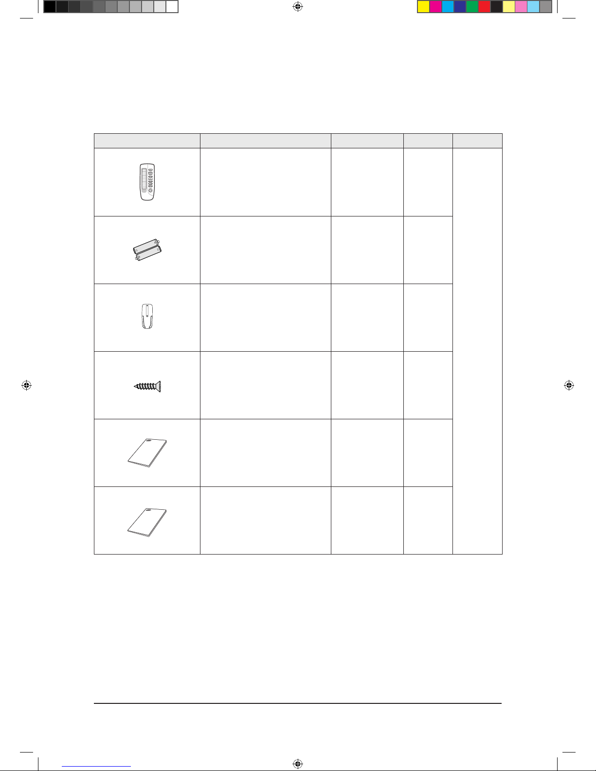
Product Specifications
Item Descriptions Code-No. Q'TY Remark
Wireless remote controller
DB93-00251G
(ARH-401)
1
Optional
Batteries for remote controller
(specification: "AAA" type)
DB47-90024A 2
Remote controller holder DB61-00204A 1
STS 2S-2x10 Tapped Screw 6002-000581 2
User’s manual DB98-05156A 1
Installation manual DB98-05184A 1
Accessories (cont.)
■ Wireless Remote controller
NS090SDXEA_E_SM_33623A(1)_1.indd 8 2011-04-08 �� 10:54:34
Samsung Electronics 2-9
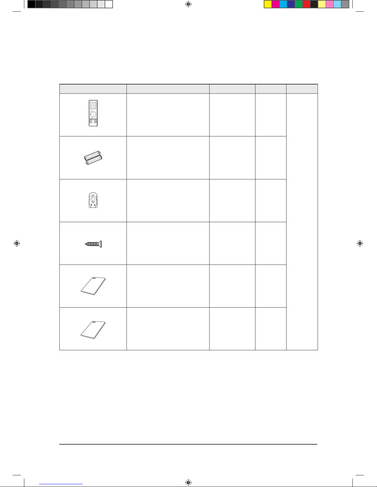
Product Specifications
Accessories (cont.)
■ Wireless Remote Controlle
Item Descriptions Code-No. Q'TY Remark
Wireless remote controller
DB93-04858C
(MR-BH01)
1
Optional
Batteries for remote controller
(specification: "AAA" type)
DB47-90024A 2
Remote controller holder DB61-03147A 1
STS 2S-2x10 Tapped Screw 6002-000581 2
User’s manual DB98-27999A 1
Installation manual DB98-27997A 1
NS090SDXEA_E_SM_33623A(1)_1.indd 9 2011-04-08 �� 10:54:34
2-10 Samsung Electronics
Product Specifications
Accessories (cont.)
■ Wireless remote controller
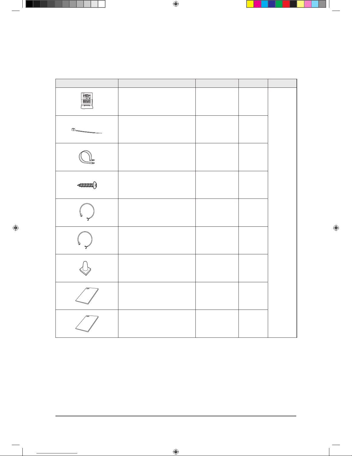
Item Descriptions Code-No. Q'TY Remark
Wired remote controller
DB97-14333C
(MWR-WH02)
1
Optional
Cable tie DB65-10088B 2
Cable clamp DB65-10074E 5
M4×16 Tapped Screw 6002-000474 7
Indoor unit power drawing cable DB39-00221A 1
Communication cable of thewired remote
controller
DB39-00933A 1
Wire joint DB39-90020A 1
User’s manual DB98-25179A 1
Installation manual DB98-25180A 1
NS090SDXEA_E_SM_33623A(1)_1.indd 10 2011-04-08 �� 10:54:35
Samsung Electronics 2-11
Product Specifications
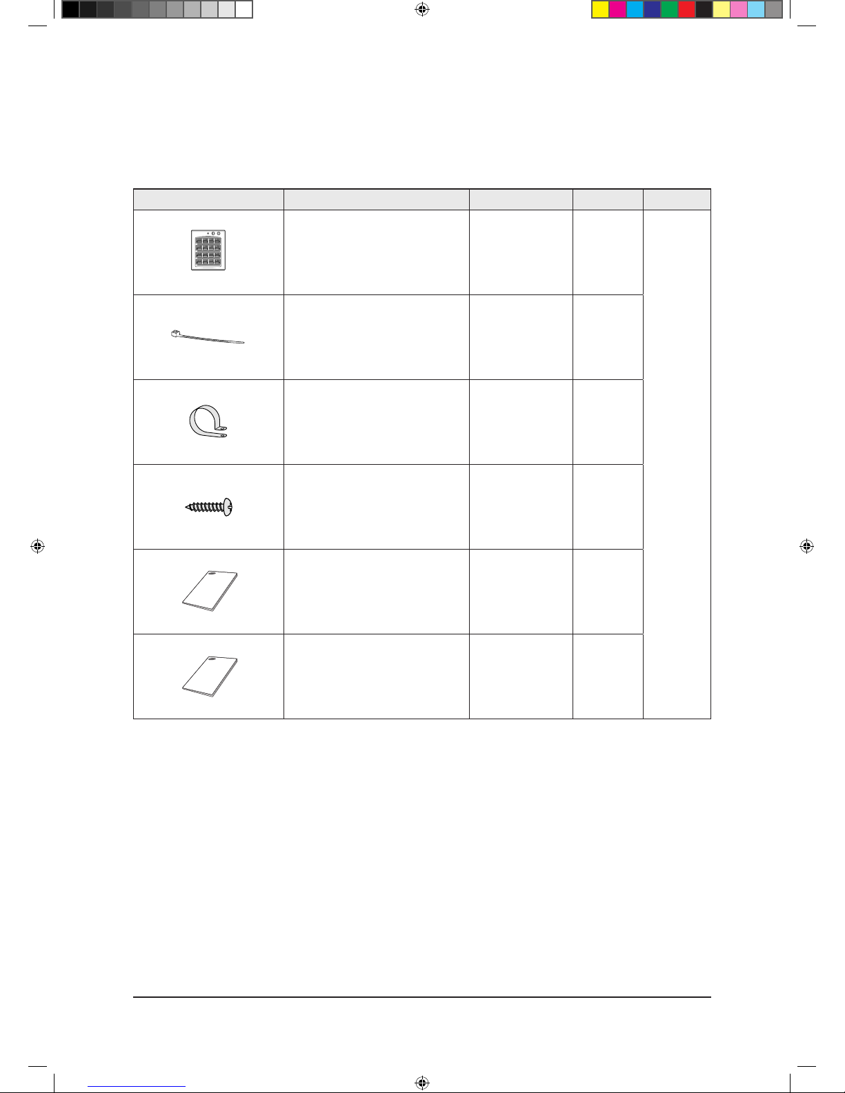
Accessories (cont.)
■ Centralized controller
Item Descriptions Code-No. Q'TY Remark
Centralized controller
DB93-03425C
(MCM-A202)
1
Optional
Cable tie DB65-10088B 2
Cable clamp DB65-10074E 5
M4x16 Tapped Screw 6002-000474 7
User’s manual DB98-12721A 1
Installation manual DB98-25773A 1
NS090SDXEA_E_SM_33623A(1)_1.indd 11 2011-04-08 �� 10:54:36
2-12 Samsung Electronics
Product Specifications
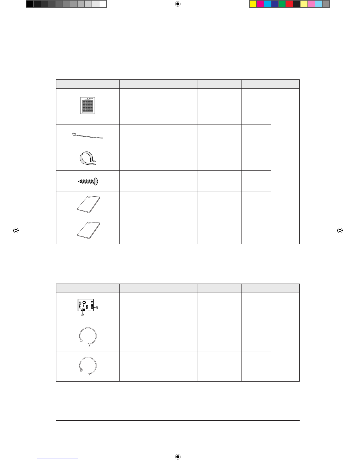
Accessories (cont.)
■ Function controller
Item Descriptions Code-No. Q'TY Remark
Function controller
DB97-01077A
(MCM-A100)
1
Optional
Cable tie DB65-10088B 2
Cable clamp DB65-10074E 6
M4x16 Tapped Screw 6002-000474 7
User’s manual DB98-27317A 1
Installation manual DB98-27315A 1
■ Transmitter
Item Descriptions Code-No. Q'TY Remark
Transmitter
DB97-00647P
(MIM-B04A)
1
Optional
Transmitter power cable DB39-00378D 1
Transmitter communication cable DB39-00253D 1
NS090SDXEA_E_SM_33623A(1)_1.indd 12 2011-04-08 �� 10:54:36
Samsung Electronics 2-13
Product Specifications
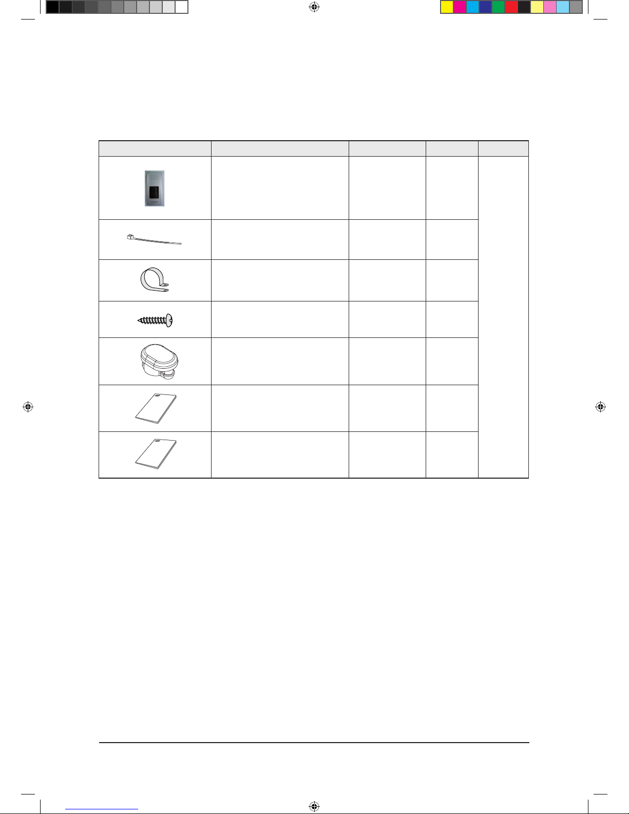
Accessories (cont.)
■ DMS(Date Management Server)
Item Descriptions Code-No. Q'TY Remark
DMS
DB93-03709B
(MIM-D00)
1
Optional
Cable tie DB65-10088B 2
Cable clamp DB65-10074D 2
M4x16 Tapped Screw 6002-000474 5
Bottom hook DB73-00320A 4
User’s manual DB98-27317A 1
Installation manual DB98-27315A 1
NS090SDXEA_E_SM_33623A(1)_1.indd 13 2011-04-08 �� 10:54:36
3-1 Samsung Electronics
Item Remarks
+SCREW DRIVER
Adjustable Wrench
(8mm, 10mm, 13mm)
Necessary Tools
3. Disassembly and Reassembly
NS090SDXEA_E_SM_33623A(1)_1.indd 1 2011-04-08 �� 10:54:36
Operating Instructions and Installation
Samsung Electronics 3-2
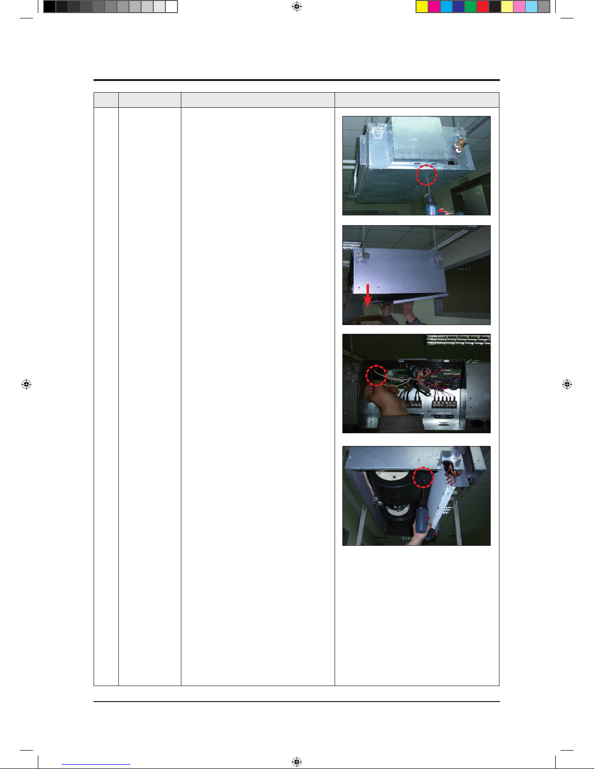
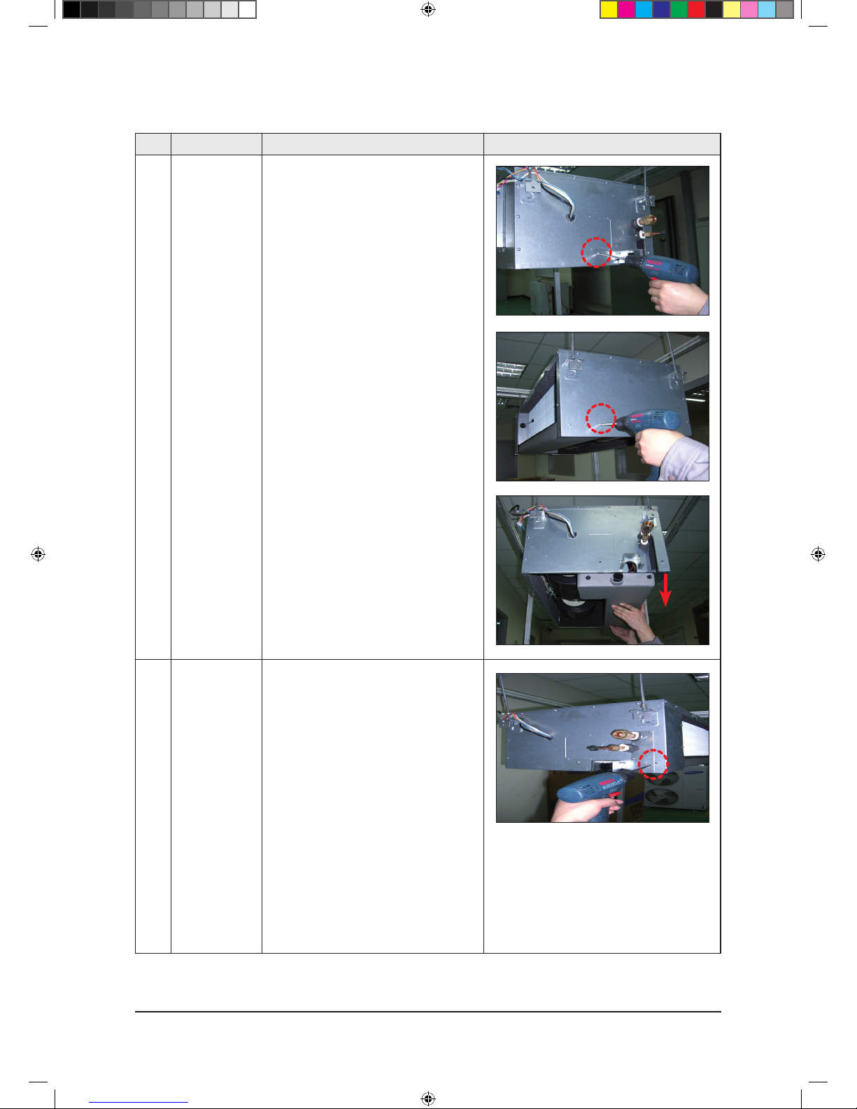
No Parts Procedure Remark
1 Blower & Motor 1) After disassembling 16 places indicating
screws, detach Ass'y Cabi Bottom Blower.
(Use +Screw Driver)
2) Detach from Ass'y Control In the capacitor
connection wire between the Motor Fan and
housing connector.
3) After disassembling 2 places indicating screws,
detach the 2 Fan Case. (Use +Screw Driver)
3-1 Indoor unit
NS090SDXEA_E_SM_33623A(1)_1.indd 2 2011-04-08 �� 10:54:37
3-3 Samsung Electronics
Disassembly and Reassembly
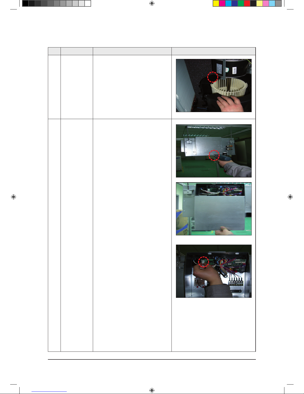
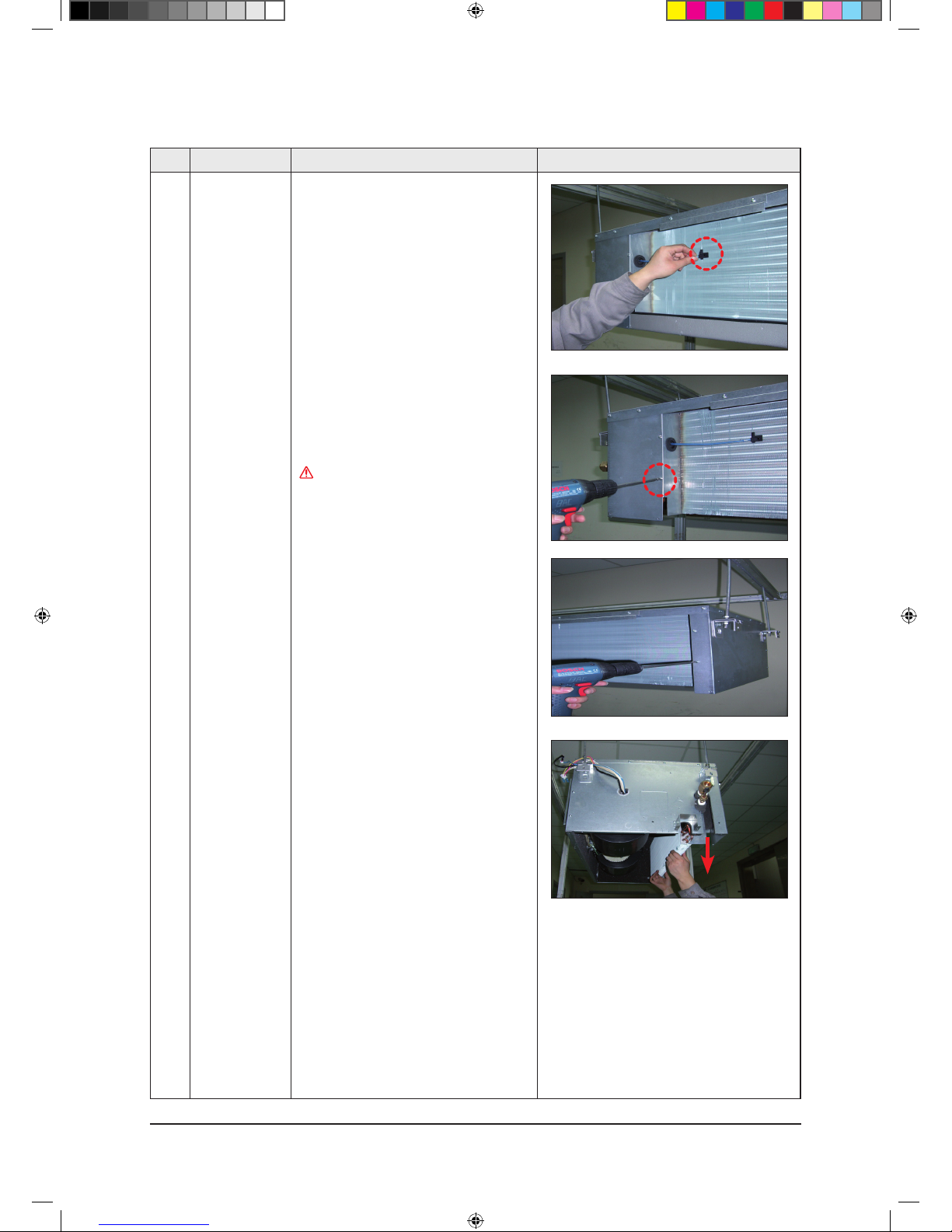
No Parts Procedure Remark
4) After disassembling 2 places indicating
screws, detach Fan Motor and Blower
from the set.
2 Control In 1) After disassembling 1 Indicating screw, detach
the Cover control. (Use +Screw Driver)
2) Detach the Motor-Fan and Sensor Connector
from the PCB.
NS090SDXEA_E_SM_33623A(1)_1.indd 3 2011-04-08 �� 10:54:38
Samsung Electronics 3-4
Disassembly and Reassembly
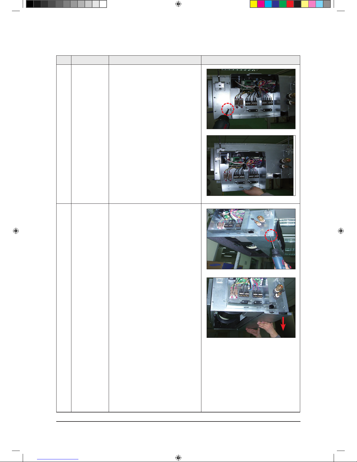
No Parts Procedure Remark
3) Disassemble 4 indicating screws and detach
Control In from the set.
3 Drain Pan Work is possible when Disassembling the Ass'y
Cabi Bottom Blower.
1) Disassemble 7 indicating screws and detach
Ass'y Cabi Bottom Drain..
NS090SDXEA_E_SM_33623A(1)_1.indd 4 2011-04-08 �� 10:54:39
3-5 Samsung Electronics
Disassembly and Reassembly
No Parts Procedure Remark
1) Disassemble 4 indicating screws and detach
the Drain Pan. (Use +Screw Driver)
(2 screws each at left and right side).
4 Evap Work is possible when Disassembling the Ass'y
Drain Pan.
1) Disassemble 5 indicating screws to detach
Cover Pipe. (Use +Screw Driver)
NS090SDXEA_E_SM_33623A(1)_1.indd 5 2011-04-08 �� 10:54:40
Samsung Electronics 3-6
Disassembly and Reassembly
No Parts Procedure Remark
2) Disassemble Sensor on the Evap.
3) Disassemble 4 indicating screws which are in
the near of Hanger Plate to detach the Evap.
(Use +Screw Driver)
(2 screws each at left and right side)
It needs 2 peoples..
NS090SDXEA_E_SM_33623A(1)_1.indd 6 2011-04-08 �� 10:54:41
3-7 Samsung Electronics
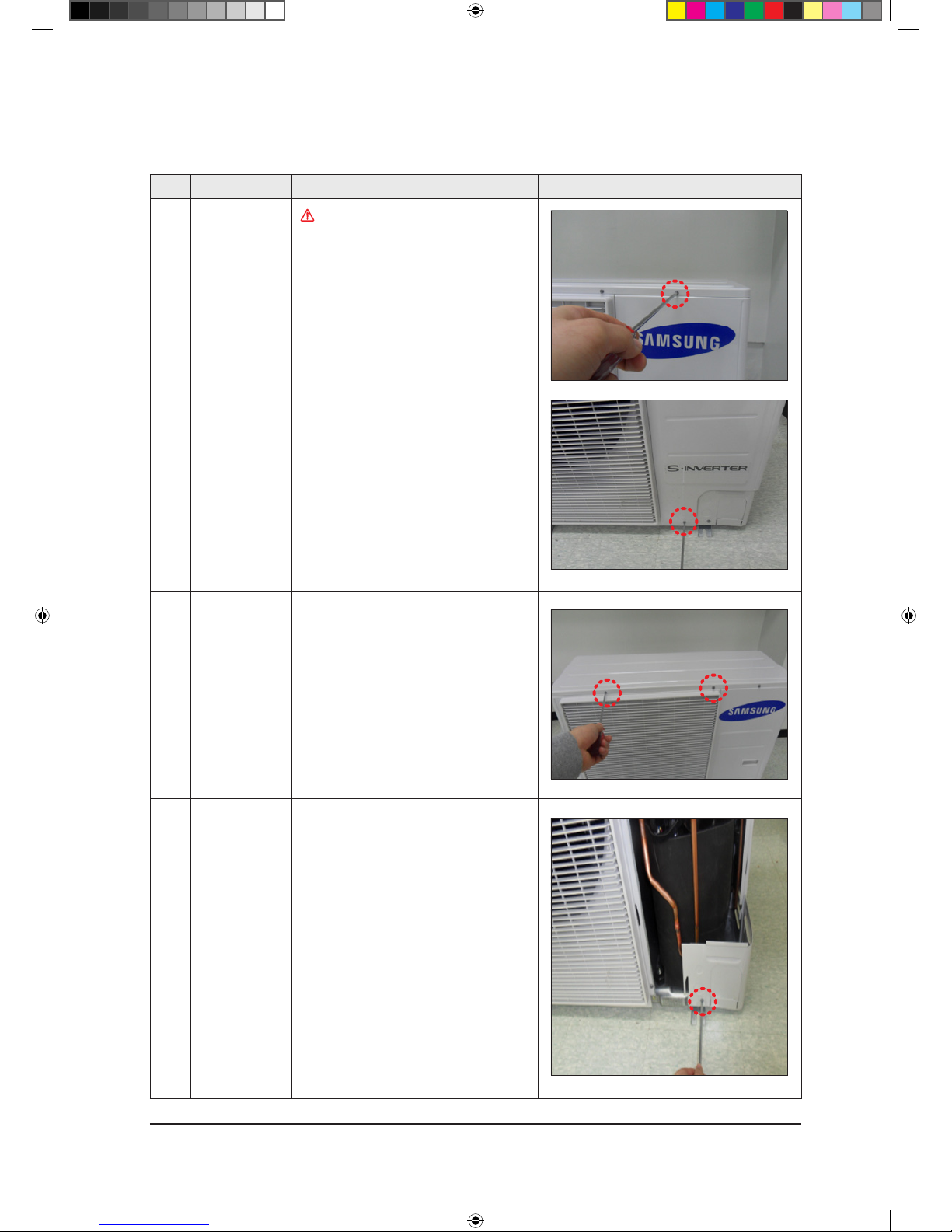
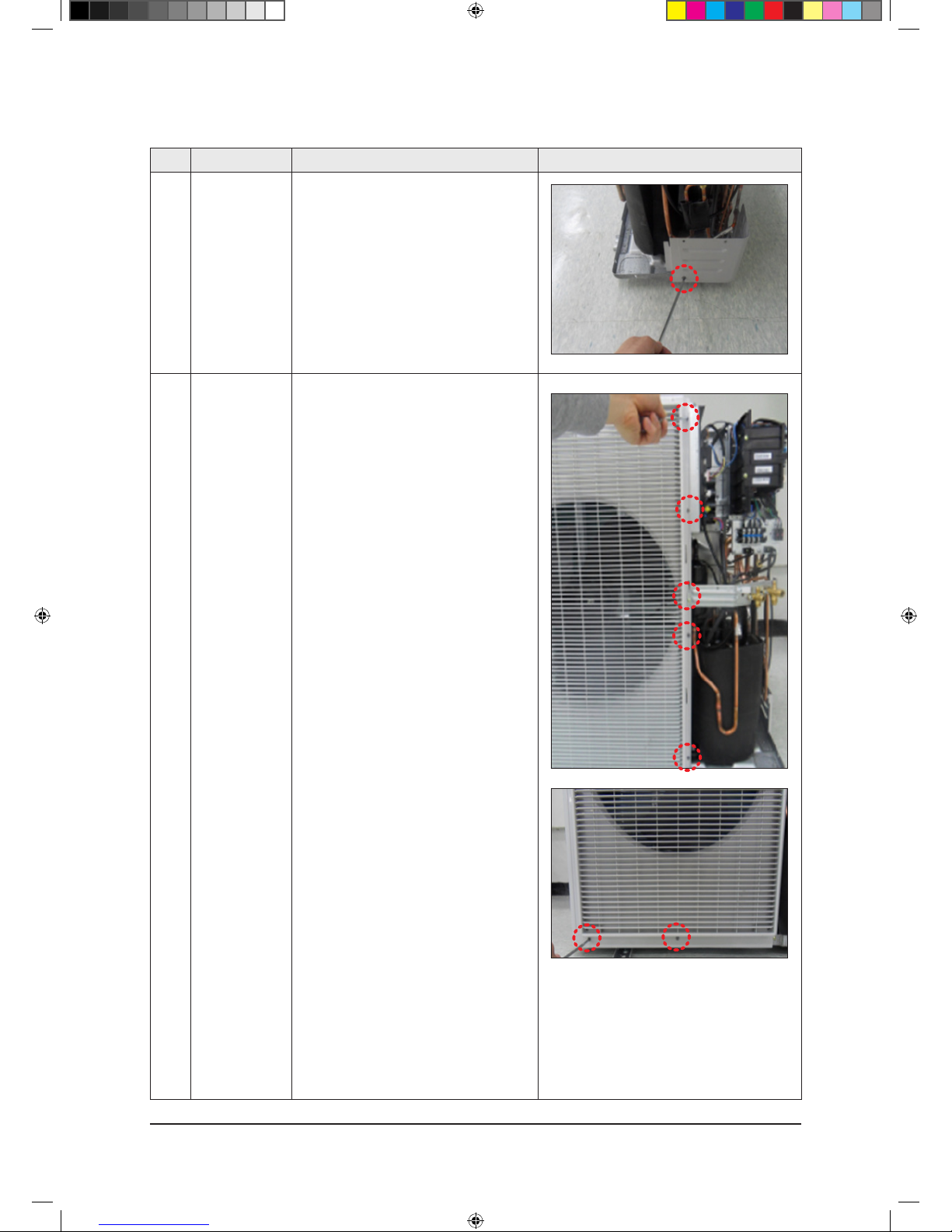
No Parts Procedure Remark
1 Cabi Front RH
You must turn off the Power before
disassembly.
1) Unscrew and remove two mounting screw
in the Cabinet Front RH. (Use +Screw Driver)
2 Cabi Top 1) Unscrew and remove 9 screws
on each side of the Cabinet-Top.
(Use +Screw Driver)
3 Cabi Install Front 1) Unscrew and remove 1 screw
in the Cabinet-Install Front.
(Use +Screw Driver)
RC090DH*/RC090SH*/RC100DH*/RC100SH
*
3-2 Outdoor Unit
NS090SDXEA_E_SM_33623A(1)_1.indd 7 2011-04-08 �� 10:54:41
Samsung Electronics 3-8
Disassembly and Reassembly
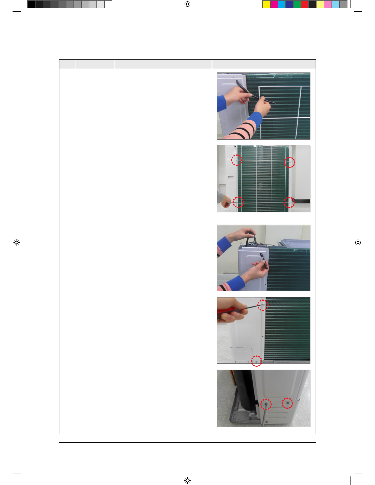
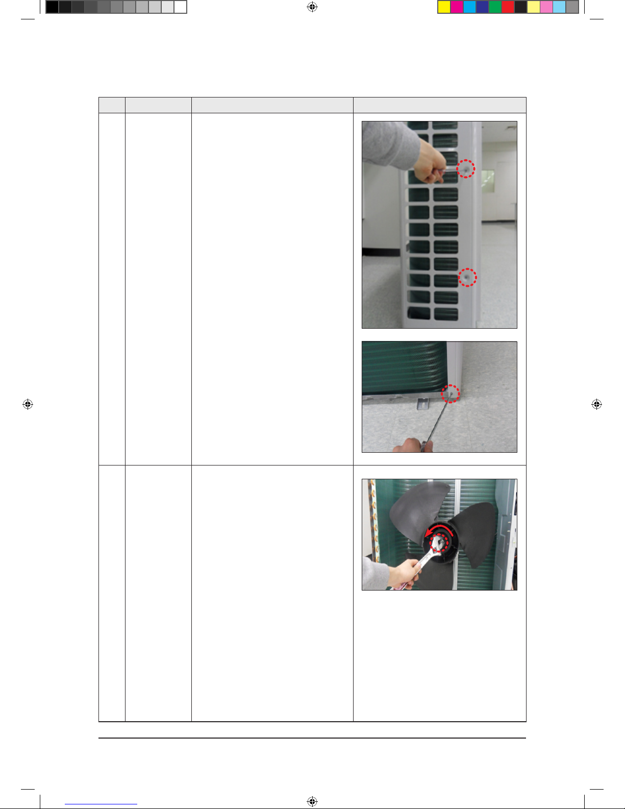
No Parts Procedure Remark
4 Guard Cond 1) Pull the sensor from Guard Cond.
2) Unscrew and remove 4 screws
in the Guard Cond.
(Use +Screw Driver)
5 Cabi Back RH 1) Pull the sensor from Cabi Back RH.
2) Unscrew and remove 4 screws
on each side of the Cabinet Back RH.
(Use +Screw Driver)
NS090SDXEA_E_SM_33623A(1)_1.indd 8 2011-04-08 �� 10:54:42
3-9 Samsung Electronics
Disassembly and Reassembly
No Parts Procedure Remark
6 Cabi Install Back 1) Unscrew and remove 1 screw
in the Cabinet-Install Back.
(Use +Screw Driver)
7 Cabi Front LF 1) Unscrew and remove 10 screws
in the Cabinet-Front LF.
(Use +Screw Driver)
NS090SDXEA_E_SM_33623A(1)_1.indd 9 2011-04-08 �� 10:54:42
Samsung Electronics 3-10
Disassembly and Reassembly
No Parts Procedure Remark
8 Fan 1) Turn 2 mounting nuts as shown in the
picture and remove it. (Use Adjustable
Wrench)
NS090SDXEA_E_SM_33623A(1)_1.indd 10 2011-04-08 �� 10:54:42
3-11 Samsung Electronics
Disassembly and Reassembly
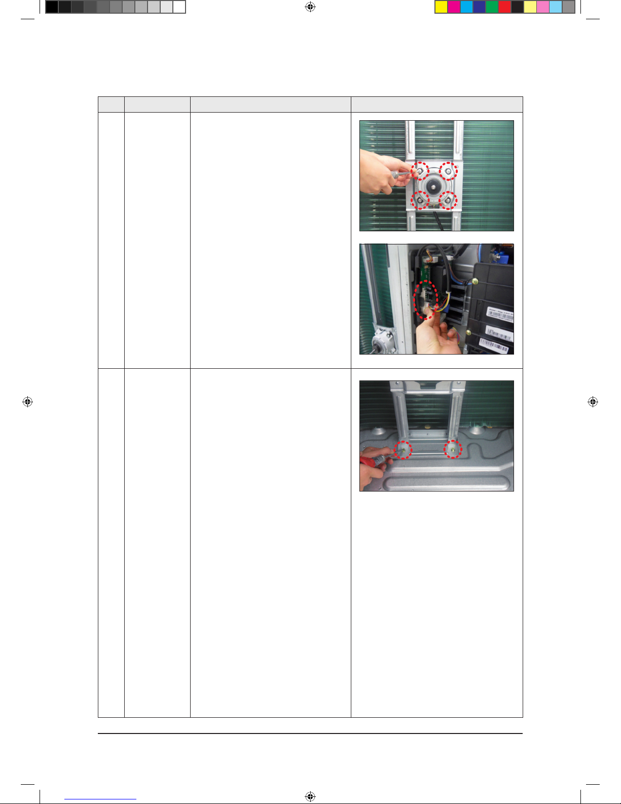
No Parts Procedure Remark
9 Motor 1) Separate the Fan Propeller.
2) Unscrew and remove the 8 Motor mounting
screws. (Use +Screw Driver)
3) Disconnect the Motor wire From
Ass'y Control Out.
10 Bracket Motor 1) Unscrew and remove 2 mounting screws
in Bracket Motor. (Use +Screw Driver)
NS090SDXEA_E_SM_33623A(1)_1.indd 11 2011-04-08 �� 10:54:43
Samsung Electronics 3-12
Disassembly and Reassembly
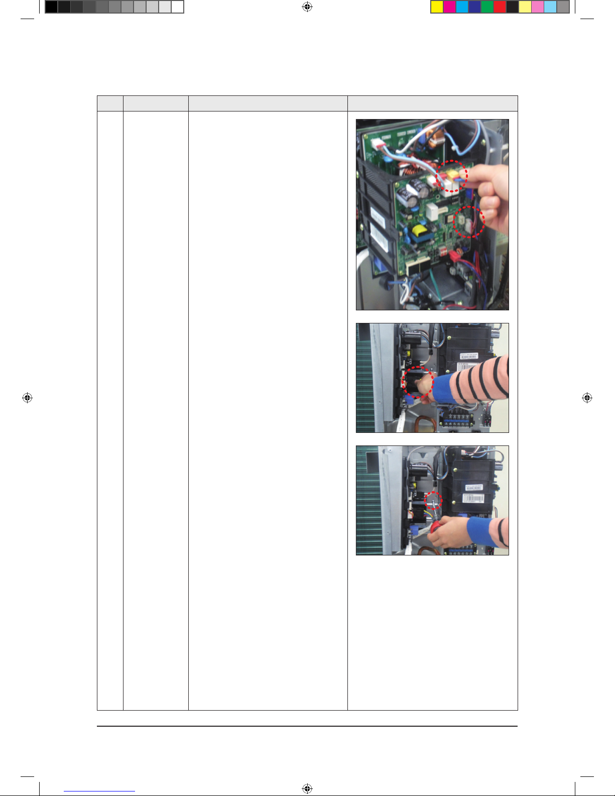
No Parts Procedure Remark
11 Control Out 1) Disconnect 4 Connecters From
Ass'y Control Out.
2) Unscrew and remove 1 mounting screw
in Control Out. (Use +Screw Driver)
3) Separate Ass'y Control Out.
NS090SDXEA_E_SM_33623A(1)_1.indd 12 2011-04-08 �� 10:54:44
 Loading...