

Samsung AC090FCASEH, AC090FCADEH, AC100FCADEH, AC100FCASEH, RC090SHXEA Installation Manual
...
ACFCADEH/ACFCADGH
ACFCAPEH/ACFCAPGH
ACFCAFEH/ACFCASEH
RCDHXE/RCDHXG
RCPHXEA/RCPHXGA
RCZHXEA/RCSHXEA
ACHCAPKH/ACHCAPNH
ACHCADKH/ACHCADNH
ACJXADH/ACJXADEH1
Air Conditioner
installation manual
ENITESPTFR
imagine the possibilities
Thank you for purchasing this Samsung product.
DE
EL
DB98-32793A-25
Contents
Safety precautions ..........................................................................................................3
Preparation for outdoor unit installation.....................................................................................5
Deciding on where to install the outdoor unit ...............................................................................6
Outdoor unit installation ..................................................................................................10
Connecting the cable .....................................................................................................11
Connecting the refrigerant pipe . . . . . . . . . . . . . . . . . . . . . . . . . . . . . . . . . . . . . . . . . . . . . . . . . . . . . . . . . . . . . . . . . . . . . . . . . . . . . . . . . . . . . . . . . . . 21
Adding refrigerant (R-410A) ...............................................................................................22
Installing DPM ............................................................................................................25
Connecting up and removing air in the circuit .............................................................................26
Cutting/Flaring the pipes.................................................................................................. 28
Performing leak tests...................................................................................................... 29
Connecting the drain hose to the outdoor unit ............................................................................29
Refrigerant pipe work .....................................................................................................30
Using stop valve ..........................................................................................................32
Interface module Installation (Optional) ...................................................................................33
Pump down Procedure....................................................................................................34
Checking correct grounding............................................................................................... 35
Testing operations ........................................................................................................36
COMMISSION DELEGATED REGULATION (EU) No 626/2011
Troubleshooting ..........................................................................................................61
i)...............................................................................................................
39
Correct Disposal of This Product
(Waste Electrical & Electronic Equipment)
(Applicable in countries with separate collection systems)
This marking on the product, accessories or literature indicates that the product and its electronic accessories (e.g.
charger, headset, USB cable) should not be disposed of with other household waste at the end of their working life. To
prevent possible harm to the environment or human health from uncontrolled waste disposal, please separate these
items from other types of waste and recycle them responsibly to promote the sustainable reuse of material resources.
Household users should contact either the retailer where they purchased this product, or their local government oce,
for details of where and how they can take these items for environmentally safe recycling.
Business users should contact their supplier and check the terms and conditions of the purchase contract. This product
and its electronic accessories should not be mixed with other commercial wastes for disposal.
2

Safety precautions
Carefully follow the precautions listed below because they are essential to guarantee the safety of the equipment.
• Always disconnect the air conditioner from the power supply before servicing it or
WARNING
General information
Carefully read the content of this manual before installing the air conditioner and store the manual in a safe place in order
to be able to use it as reference after installation.
For maximum safety, installers should always carefully read the following warnings.
Store the operation and installation manual in a safe location and remember to hand it over to the new owner if the air
conditioner is sold or transferred.
This manual explains how to install an indoor unit with a split system with two SAMSUNG units. The use of other types
of units with dierent control systems may damage the units and invalidate the warranty. The manufacturer shall not be
responsible for damages arising from the use of non compliant units.
The manufacturer shall not be responsible for damage originating from unauthorized changes or the improper
connection of electric and requirements set forth in the “Operating limits” table, included in the manual, shall
immediately invalidate the warranty.
The air conditioner should be used only for the applications for which it has been designed: the indoor unit is not suitable
to be installed in areas used for laundry.
Do not use the units if damaged. If problems occur, switch the unit o and disconnect it from the power supply.
In order to prevent electric shocks, res or injuries, always stop the unit, disable the protection switch and contact
SAMSUNG’s technical support if the unit produces smoke, if the power cable is hot or damaged or if the unit is very noisy.
Always remember to inspect the unit, electric connections, refrigerant tubes and protections regularly. These operations
should be performed by qualied personnel only.
The unit contains moving parts, which should always be kept out of the reach of children.
Do not attempt to repair, move, alter or reinstall the unit. If performed by unauthorized personnel, these operations may
cause electric shocks or res.
Do not place containers with liquids or other objects on the unit.
All the materials used for the manufacture and packaging of the air conditioner are recyclable.
The packing material and exhaust batteries of the remote controller(optional) must be disposed of in accordance with
current laws.
The air conditioner contains a refrigerant that has to be disposed of as special waste. At the end of its life cycle, the air
conditioner must be disposed of in authorized centers or returned to the retailer so that it can be disposed of correctly
and safely.
This appliance is not intended for use by persons (including children) with reduced physical, sensory or mental
capabilities, or lack of experience and knowledge, unless they have been given supervision or instruction concerning use
of the appliance by a person responsible for their safety. Children should be supervised to ensure that they do not play
with the appliance.
For use in Europe : This appliance can be used by children aged from 8 years and above and persons with reduced
physical, sensory or mental capabilities or lack of experience and knowledge if they have been given supervision or
instruction concerning use of the appliance in a safe way and understand the hazards involved. Children shall not play
with the appliance. Cleaning and user maintenance shall not be made by children without supervision.
accessing its internal components.
• Verify that installation and testing operations are performed by qualied personnel.
• Verify that the air conditioner is not installed in an easily accessible area.
ENGLISH
3

Safety precautions
Installing the unit
IMPORTANT: When installing the unit, always remember to connect rst the refrigerant tubes, then the electrical lines.
Upon receipt, inspect the product to verify that it has not been damaged during transport. If the product appears
damaged, DO NOT INSTALL it and immediately report the damage to the carrier or retailer (if the installer or the
authorized technician has collected the material from the retailer.)
After completing the installation, always carry out a functional test and provide the instructions on how to operate the air
conditioner to the user.
Do not use the air conditioner in environments with hazardous substances or close to equipment that release free ames
to avoid the occurrence of res, explosions or injuries.
Our units should be installed in compliance with the spaces shown in the installation manual, to ensure accessibility from
both sides and allow repairs or maintenance operations to be carried out. The unit’s components should be accessible
and easy to disassemble without endangering people and objects.
For this reason, when provisions of the installation manual are not complied with, the cost required to access and repair
the units (in SAFETY CONDITIONS, as set out in prevailing regulations) with harnesses, ladders, scaolding or any other
elevation system will NOT be considered part of the warranty and will be charged to the end customer.
Power supply line, fuse or circuit breaker
Always make sure that the power supply is compliant with current safety standards. Always install the air conditioner in
compliance with current local safety standards.
Always verify that a suitable grounding connection is available.
Verify that the voltage and frequency of the power supply comply with the specications and that the installed power is
sucient to ensure the operation of any other domestic appliance connected to the same electric lines.
Always verify that the cut-o and protection switches are suitably dimensioned.
Verify that the air conditioner is connected to the power supply in accordance with the instructions provided in the
wiring diagram included in the manual.
Always verify that electric connections (cable entry, section of leads, protections…) are compliant with the electric
specications and with the instructions provided in the wiring scheme. Always verify that all connections comply with
the standards applicable to the installation of air conditioners.
Devices disconnected from the power supply should be completely disconnected in the condition of overvoltage
category.
Always disassemble the electric lines before the refrigerant tubes.
4
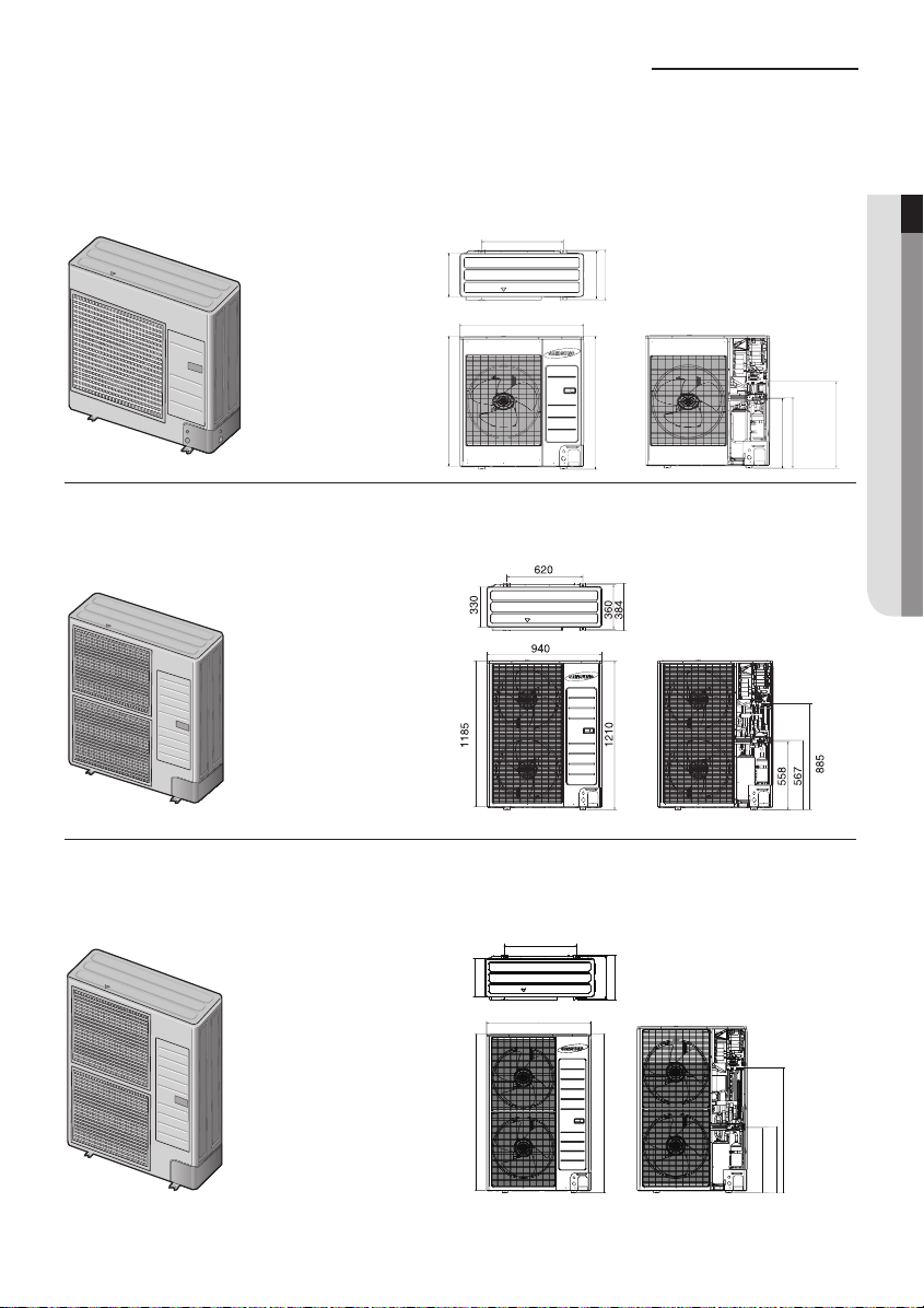
Preparation for outdoor unit installation
The air conditioner uses R-410A refrigerant.
A Type
Heat pump
AC090FCAEH/AC100FCADH/AC100FCASEH/RC090HXEA/RC100DHXA/RC100SHXEA/AC071HCAPKH/
AC090HCADH/AC100HCADH/AC120HCADH/AC100JXADH/AC120JXADH/AC100JXADEH1
620
384
330
940
360
998
(Unit : mm)
537
528
ENGLISH
675
B Type
Heat pump
C Type
Heat pump
AC100FCAPH/RC100DHXEH/RC100PHXA/RC100DHXEG/RC125HX/RC125DHXEG/RC140DHXEB/RC140DHXGA/
AC090HCAPKH/AC140HCADH/AC140JXADH
AC100FCAFH/RC100ZHXEA/RC140PHXA/RC140DHXEH/RC140DHXEG/RC155DHXEH/RC155DHXEG/RC180DHXGH/
RC180DHXGG/AC100HCAPH/AC120HCAPH/AC140HCAPH
620
330
940
1395
360
1420
384
1095
558
567
5
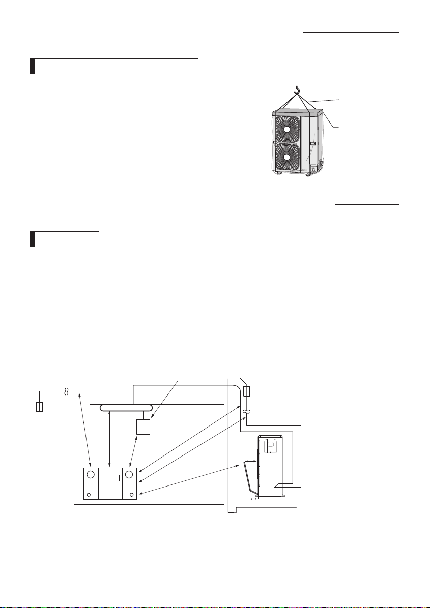
Preparation for outdoor unit installation
Moving the Outdoor Unit by Wire Rope
Fasten the outdoor unit by two 8m or longer wire ropes as shown at the
gure. To prevent from damage or scratches, insert a piece of cloth between
the outdoor unit and rope, then move the unit.
The appearance of the unit may be dierent from the picture depending
on the model.
Wire rope
Plate protection
cloth
Deciding on where to install the outdoor unit
Outdoor Unit
The outdoor unit must not be placed on its side or upside down, as the compressor lubrication oil will run into the cooling
circuit and seriously damage the unit.
Choose a location that is dry and sunny, but not exposed to direct sunlight or strong winds.
Do not block any passageways or thoroughfares.
Choose a location where the noise of the air conditioner when running and the discharged air do not disturb any
neighbours.
Choose a position that enables the pipes and cables to be easily connected to the indoor unit.
Install the outdoor unit on a at, stable surface that can support its weight and does not generate any unnecessary noise
and vibration.
Position the outdoor unit so that the air ow is directed towards the open area.
Maintain sucient clearance around the outdoor unit, especially from a radio, computer, stereo system, etc.
Indoor Unit
Control
Fuse
Fuse
1m or more
1.5m or more
If the outdoor unit is installed at a height, ensure that its base is rmly xed in position.
Make sure that the water dripping from the drain hose runs away correctly and safely.
1m or more
Stereo
1.5m or more
1.5m or more
1.5m or more
Outdoor Unit
300mm
200mm
6
Air Guide Duct
(This product is not
provided by Samsung)
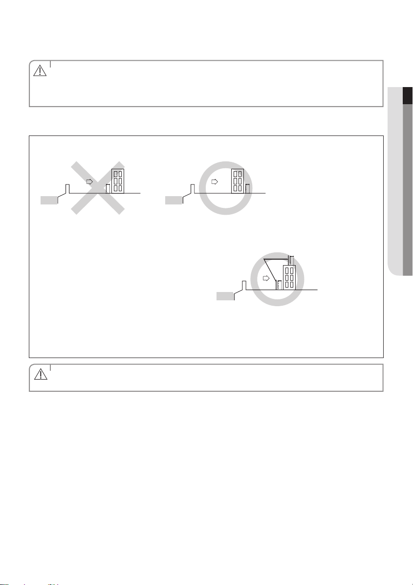
When you install the outdoor unit at wayside, you should install it above 2m height or make sure that the heat from the
outdoor unit shouldn't be in direct contact with passersby. (The ground for application :The revision of regulation for
facility in building by the law of the Ministry of Construction and Transportation.
• You have just purchased a system air conditioner and it has been installed by your installation specialist.
• This device must be installed according to the national electrical rules.
CAUTION
• With an outdoor unit having net weight upper than 60kg, we suggest do not install it suspended on wall, but
considering oor standing one.
When installing the outdoor unit near seashore, make sure it is not directly exposed to sea breeze. If you can not nd a
adequate place without direct see breeze, protection wall should be constructed.
- Install the outdoor unit in a place (such as near buildings etc.) where it can be prevented from sea breeze which can
damage the outdoor unit.
Outdoor unit
Sea breeze Sea breeze
Outdoor unit
ENGLISH
Sea
Sea
- If you cannot avoid installing the outdoor unit by the seashore, construct a protection wall around to block the sea
breeze.
• Protection wall should be constructed with a solid
material such as concrete to block the sea breeze
and the height and the width of the wall should be
1.5 times larger than the size of the outdoor unit.
Protection wall
Sea breeze
Outdoor unit
Also, secure over 700mm between the protection
wall and the outdoor unit for exhausted air to
Sea
ventilate.
- Install the outdoor unit in a place where water can drain smoothly.
• If you cannot nd a place satisfying above conditions, please contact manufacturer. Make sure to clean the sea water
and the dust on the outdoor unit heat exchanger and spread corrosion inhibitor on heat exchanger. (At least one time
per one year.)
• Depending on the condition of power supply, unstable power or voltage may cause malfunction of the parts or
control system. (At the ship or places using power supply from electric generator, etc).
CAUTION
7
Deciding on where to install the outdoor unit
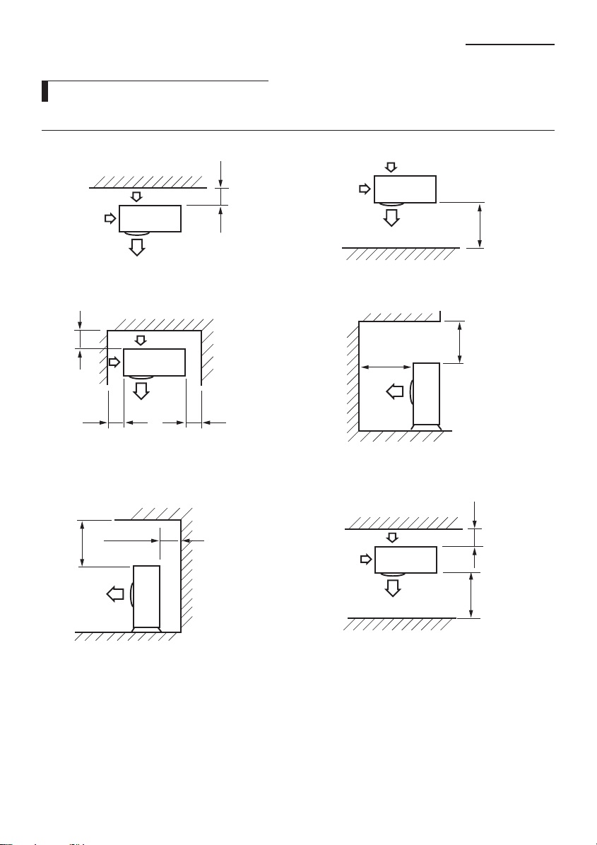
Space Requirements for Outdoor Unit
When installing 1 outdoor unit
300 or more
When the air outlet is opposite the wall When the air outlet is towards the wall
(Unit : mm)
1500 or more
300 or more
300 or more
When 3 sides of the outdoor unit are blocked by the wall The upper part of the outdoor unit and the air outlet is
300 or more
600 or more
The upper part of the outdoor unit and the air outlet is
opposite the wall
600 or more
towards the wall
When front and rear side of the outdoor unit is towards
the wall
2000 or more
1500 or more
300 or more1500 or more
8
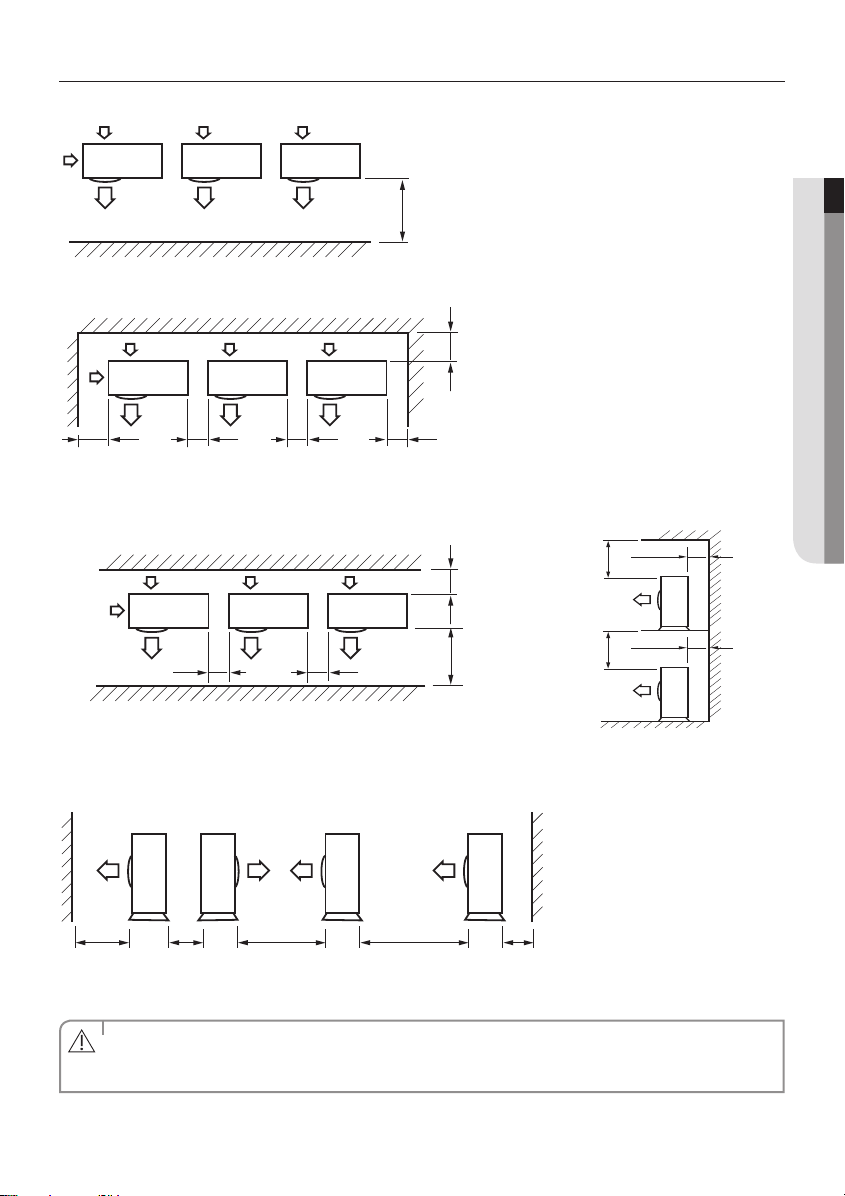
When installing more than 1 outdoor unit
When the air outlet is towards the wall
300 or more 600 or more 600 or more 600 or more
When 3 sides of the outdoor unit are blocked by the wall
(Unit : mm)
ENGLISH
1500 or more
300 or more
300 or more
500 or more
300 or more
500 or more
600 or more
300 or more1500 or more
600 or more
When front and rear side of the outdoor unit is towards the wall The upper part of the outdoor unit and
the air outlet is towards the wall
1500 or more 600 or more 3000 or more 300 or more3000 or more
When front and rear side of the outdoor unit is towards the wall
• The units must be installed according to distances declared, in order to permit accessibility from each side, either
to guarantee correct operation of maintenance or repairing products.
CAUTION
The unit’s parts must be reachable and removable completely under safety condition (for people or things).
9
Outdoor unit installation
620
940
330
360
384
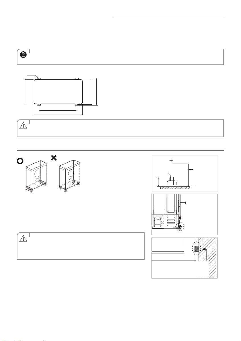
The outdoor unit must be installed on a rigid and stable base to avoid any increase in the noise level and vibration, particularly if the outdoor unit is
to be installed in a location exposed to strong winds or at a height, the unit must be xed to an appropriate support(wall or ground).
Fix the outdoor unit with anchor bolts.
• The anchor bolt must be 20mm or higher from the base surface.
NOTE
Anchor bolt hole
(Unit : mm)
• Make a drain outlet around the base for outdoor unit drainage.
CAUTION
• If the outdoor unit is installed on the roof, you have to check the ceiling strength and waterproof the unit.
Outdoor Unit Support
Outdoor
Unit
Anchor bolt
20mm
OUTDOOR UNIT INSTALLED ON THE WALL BY RACK
Ensure the wall will be able to suspend the weight of rack and outdoor
unit ;
Install the rack close to the column as much as possible ;
Install proper grommet in order to reduce noise and residual vibration
transferred by outdoor unit towards wall.
When installing air guide duct
• Check and make sure that screws do not damage the copper
CAUTION
pipe.
• Secure air guide duct on guard fan.
Soft rubber designed to cut o
vibration from rack to wall.
(not supplied with product)
Outdoor
Unit
Support
Base Surface
Designed to
cut o residual
vibration from
outdoor unit to
rack.
(not supplied with
product)
10
Connecting the cable
Two electronic cables must be connected to the outdoor unit.
The connection cord between indoor unit and outdoor unit.
The power cable between outdoor unit and auxiliary circuit breaker.
Specially for Russian and European market, before installation, the supply authority should be consulted to determine the
supply system impendance to ensure compliance.
• During the unit installation make rst refrigerant connections and then electrical connections. If unit is
uninstalled rst disconnect electrical cables, then refrigerant connections.
CAUTION
• Connect the air conditioner to grounding system before performing the electrical connection.
• When installing the unit, you shouldn't use inter connection wire.
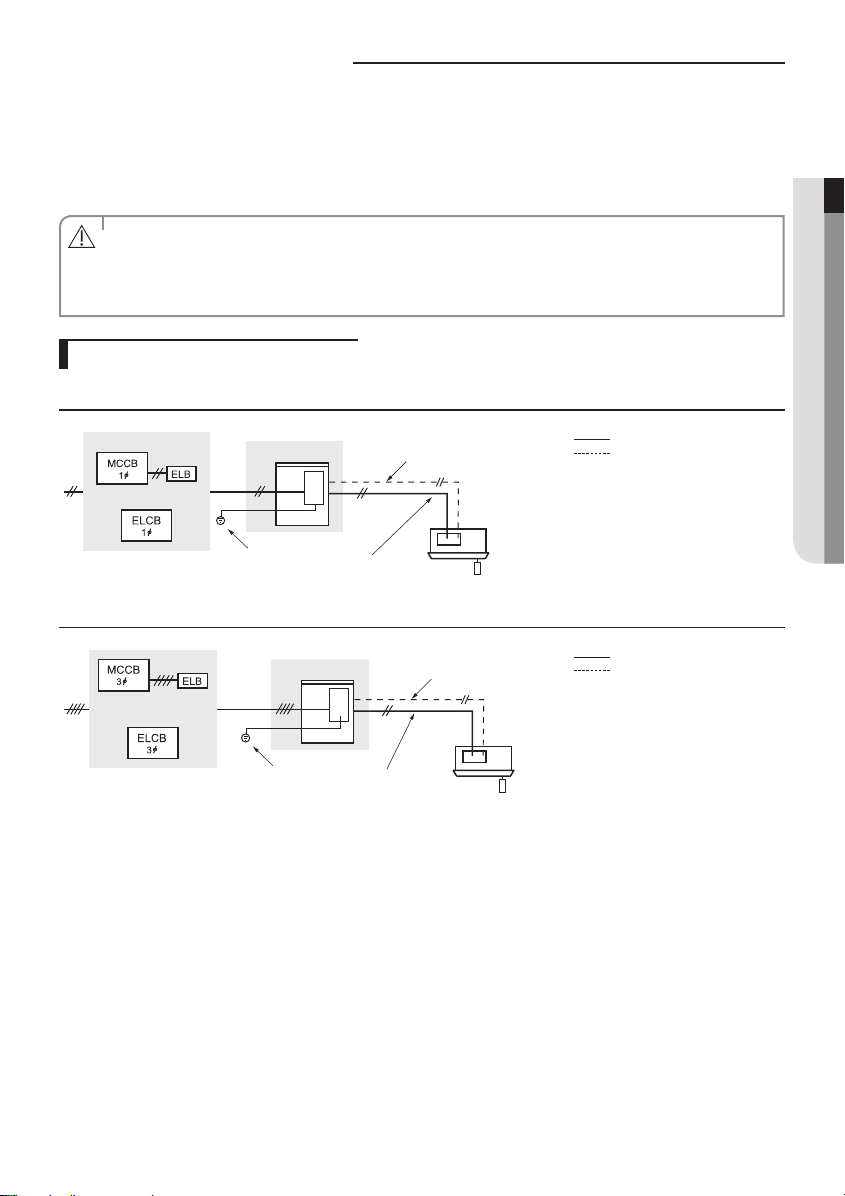
Example of Air Conditioner System
When using ELCB for 1 phase
ENGLISH
Outdoor Unit
OR
Grounding
Communication cable
Indoor Unit
Power cable
Power cable
Communication cable
When using ELCB for 3 phase 4 wires
Outdoor Unit
OR
Grounding
Communication cable
Indoor Unit
Power cable
If an outdoor unit is installed in a place in danger of an electric leak or submergence, you must install the ELCB.
Power cable
Communication cable
11
Connecting the cable
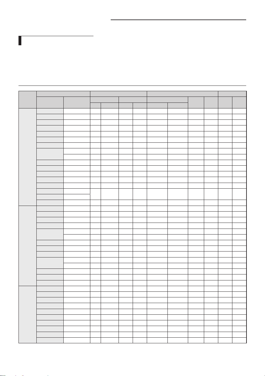
Power Cable Specications
The power cable is not supplied with air conditioner.
- Select the power supply cable in accordance with relevant local and national regulations.
- Wire size must comply with the applicable local and national code.
- Specications for local wiring power cord and branch wiring are in compliance with local cord.
Single Phase
Type of
outdoor
unit
AC090FCADEH AC090FB4DEH 50 220-240 198 264 24 24 0.7 24.7 24.7 30.0
AC090FCAPEH AC090FB4PEH 50 220-240 198 264 24 24 1.0 25.0 25.0 30.0
AC090FCASEH AC090FBMSEH 50 220-240 198 264 22 22 1.5 23.5 23.5 27.5
AC100FCADEH AC100FB4DEH 50 220-240 198 264 24 24 0.7 24.7 24.7 30.0
AC100FCASEH AC100FBMSEH 50 220-240 198 264 22 22 1.5 25.0 25.0 30.0
A
AC071HCAPKH AC071HBMPKH 50/60 220-240 198 264 24 24 2.7 26.7 26.7 30.0
AC120HCADKH AC120HBMDKH 50/60 220-240 198 264 24 24 2.7 26.7 26.7 30.0
AC100HCADKH AC100HBMDKH 50/60 220-240 198 264 24 24 2.7 26.7 26.7 30.0
AC090HCADKH AC090HBMDKH 50/60 220-240 198 264 24 24 2.7 26.7 26.7 30.0
AC100JXADEH AC100JNCDEH
AC100JXADEH1 AC100JNCDEH1
AC120JXADEH AC120JNCDEH 50 220-240 198 264 24 24 2.7 26.7 26.7 30.0
AC100FCAPEH AC100FB4PEH 50 220-240 198 264 24 24 1.0 25.0 25.0 30.0
B
AC090HCAPKH AC090HBMPKH 50/60 220-240 198 264 24 24 2.7 26.7 26.7 30.0
AC140HCADKH AC140HBMDKH 50/60 220-240 198 264 24 24 2.7 26.7 26.7 30.0
AC140JXADEH AC140JNCDEH 50 220-240 198 264 24 24 2.7 26.7 26.7 30.0
AC100FCAFEH AC100FB4FEH 50 220-240 198 264 24 24 1.0 25.0 25.0 30.0
C
AC140HCAPKH AC140HBMPKH 50/60 220-240 198 264 32 32 2.7 34.7 34.7 40.0
AC120HCAPKH AC120HBMPKH 50/60 220-240 198 264 32 32 2.7 34.7 34.7 40.0
AC100HCAPKH AC100HBMPKH 50/60 220-240 198 264 32 32 2.7 34.7 34.7 40.0
Model Outdoor Units Input Current [A] Power Supply
Outdoor Unit Indoor Unit
RC090PHXEA NS0904PXEA 50 220-240 198 264 24 24 1.0 25.0 25.0 30.0
RC090SHXEA NS090SSXEA 50 220-240 198 264 22 22 1.5 23.5 23.5 27.5
RC100DHXEA
RC100SHXEA NS100SSXEA 50 220-240 198 264 22 22 1.5 23.5 23.5 27.5
RC100PHXEA NS1004PXEA 50 220-240 198 264 24 24 1.0 25.0 25.0 30.0
RC100DHXEH NS100HHXEH 50 220-240 198 264 24 24 2.0 26.0 26.0 30.0
RC100DHXEG NS100HHXEG 50 220-240 198 264 24 24 2.0 26.0 26.0 30.0
RC125DHXEB
RC125PHXEA NS1254PXEA 50 220-240 198 264 24 24 1.0 25.0 25.0 30.0
RC125DHXEH NS125HHXEH 50 220-240 198 264 24 24 2.8 26.8 26.8 30.0
RC125DHXEG NS125HHXEG 50 220-240 198 264 24 24 2.8 26.8 26.8 30.0
RC140DHXEB
RC140PHXEA NS1404PXEA 50 220-240
RC100ZHXEA NS1004ZXEA 50 220-240 198 264 24 24 1.0 25.0 25.0 30.0
RC140DHXEH NS140HHXEH 50 220-240 198 264 32 32 3.5 35.5 35.5 40.0
RC140DHXEG NS140HHXEG 50 220-240 198 264 32 32 3.5 35.5 35.5 40.0
RC155DHXEH NS155HHXEH 50 220-240 198 264 32 32 4.6 36.6 36.6 40.3
RC155DHXEG NS155HHXEG 50 220-240 198 264 32 32 4.6 36.6 36.6 40.3
NS1004DXEA 50 220-240 198 264 24 24 0.7 24.7 24.7 30.0
NS100SDXEA 50 220-240 198 264 24 24 1.5 25.5 25.5 30.0
NS1254DXEA 50 220-240 198 264 24 24 1.0 25.0 25.0 30.0
NS125SDXEA 50 220-240 198 264 24 24 2.0 26.0 26.0 30.0
NS1404DXEA 50 220-240 198 264 24 24 1.0 25.0 25.0 30.0
NS140SDXEA 50 220-240 198 264 24 24 2.0 26.0 26.0 30.0
Rated Voltage Range Outdoor (Down_Amp)
Hz Volts Min. Max. Cooling Heating
50 220-240 198 264 22 22 2.7 24.7 24.7 30.0
198 264 32 32 1.0 33.0 33.0 40.0
Indoor Total MCA MFA
12
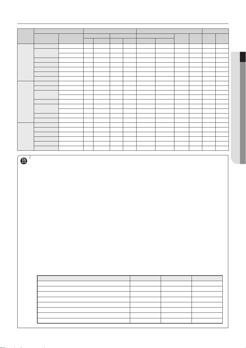
3 Phase
Type of
outdoor
unit
AC100FCADGH AC100FB4DEH 50 380-415 342 456.5 12 12 0.7 12.7 12.7 15.0
AC120HCADNH AC120HBMDKH 50/60 380-415 342 418 12 12 2.7 14.7 14.7 16.2
A
AC100HCADNH AC100HBMDKH 50/60 380-415 342 418 12 12 2.7 14.7 14.7 16.2
AC090HCADNH AC090HBMDKH 50/60 380-415 342 418 12 12 2.7 14.7 14.7 16.2
AC100JXADGH AC100JNCDEH 50 380-415 342 418 12 12 2.7 14.7 14.7 16.2
AC120JXADGH AC120JNCDEH 50 380-415 342 418 12 12 2.7 14.7 14.7 16.2
AC100FCAPGH AC100FB4PEH 50 380-415 342 456.5 12 12 1.0 13.0 13.0 15.0
B
AC140HCADNH AC140HBMDKH 50/60 380-415 342 418 12 12 2.7 14.7 14.7 16.2
AC140JXADGH AC140JNCDEH 50 380-415 342 418 12 12 2.7 14.7 14.7 16.2
C
AC140HCAPNH AC140HBMPKH 50/60 380-415 342 418 12 12 2.7 14.7 14.7 16.2
AC120HCAPNH AC120HBMPKH 50/60 380-415 342 418 12 12 2.7 14.7 14.7 16.2
AC100HCAPNH AC100HBMPKH 50/60 380-415 342 418 12 12 2.7 14.7 14.7 16.2
Model Outdoor Units Input Current [A] Power Supply
Outdoor Unit Indoor Unit
RC100DHXGA
RC100PHXGA NS1004PXEA 50 380-415 342 456.5 12 12 1.0 13.0 13.0 15.0
RC125DHXGA
RC125PHXGA NS1254PXEA 50 380-415 342 456.5 12 12 1.0 13.0 13.0 15.0
RC140DHXGA
RC140PHXGA NS1404PXEA 50 380-415 342 456.5 12 12 1.0 13.0 13.0 15.0
RC180DHXGH NS180HHXEH 50 380-415 342 456.5 12 12 2.9 14.9 14.9 16.4
RC180DHXGG NS180HHXEG 50 380-415 342 456.5 12 12 2.9 14.9 14.9 16.4
NS1004DXEA 50 380-415 342 456.5 12 12 0.7 12.7 12.7 15.0
NS100SDXEA 50 380-415 342 456.5 12 12 1.5 13.5 13.5 15.0
NS1254DXEA 50 380-415 342 456.5 12 12 1.0 13.0 13.0 15.0
NS125SDXEA 50 380-415 342 456.5 12 12 2.0 14.0 14.0 15.4
NS1404DXEA 50 380-415 342 456.5 12 12 1.0 13.0 13.0 15.0
NS140SDXEA 50 380-415 342 456.5 12 12 2.0 14.0 14.0 15.4
Rated Voltage Range Outdoor (Down_Amp)
Hz Volts Min. Max. Cooling Heating
Indoor Total MCA MFA
1. Voltage range
Units are suitable for use on electrical systems where voltage supplied to unit terminal is not below or above
NOTE
listed range limits
2. Maximum allowable voltage variation between phases is 2%.
3. Wire size & type must comply with the applicable local and national code.
Wire size : Based on the value of MCA.
Wire type : 60245 IEC57(IEC) or H05RN-F(CENELEC) grade or more.
4. MFA is used to select the circuit breaker and the ground fault circuit interrupter (earth leakage circuit breaker).
5. MCA represents maximum input current.
MFA represents capacity which may accept MCA
Abbreviations
MCA : Min. Circuit Amps. (A)
MFA : Max. Fuse Amps. (A)
6. This equipment complies with IEC 61000-3-12 provided that the short-circuit power Ssc is greater than or
equal to Ssc(*2) at the interface point between the user’s supply and the public system. It is the responsibility
of the installer or user of the equipment to ensure, by consultation with the distribution network operator if
necessary, that the equipment is connected only to a supply with a short-circuit power Ssc greater than or
equal to Ssc(*2).
[Ssc (*2)]
Model Ssc[MVA] Model Ssc[MVA]
AC140HCAPKH 2.715 AC090HCADKH 2.954
AC140HCAPNH 2.074 AC090HCADNH 2.075
AC140HCADKH, AC140JXADEH 2.996 AC120HCAPKH 3.02
AC140HCADNH, AC140JXADGH 2.064 AC120HCAPNH 2.083
AC120HCADKH, AC120JXADEH 3.365 AC100HCAPKH 3.439
AC120HCADNH, AC120JXADEH 2.086 AC100HCAPNH 2.076
AC100HCADKH, AC100JXADEH, AC100JXADEH1 3.157 AC090HCAPKH 3.299
AC100HCADNH, AC100JXADGH 2.075 AC071HCAPKH 3.329
ENGLISH
13
Connecting the cable
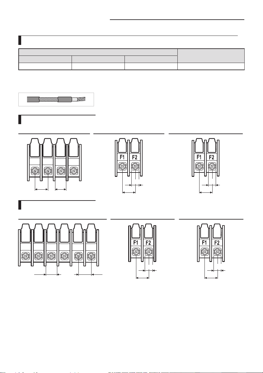
Between Indoor unit and Outdoor unit Connection Cable Specications(Common in use)
Power supply
Power supply Max/Min(V)
1Φ, 220-240V, 50Hz ±10%
Power supply cords of parts of appliances for outdoor use shall not be lighter than polychloroprene sheathed exible
cord. (Code designation IEC:60245 IEC 57 / CENELEC: H05RN-F or IEC:60245 IEC 66 / CENELEC: H07RN-F)
When installing the indoor unit in a computer room or net work room, use the
double shielded (Tape aluminum / polyester braid + copper ) cable of FROHH2R
type.
Indoor Power Cable
2.5mm² , 3wires
Communation Cable
0.75~1.5mm², 2wires
1-phase terminal block spec
AC power : M5 screw Communication : M4 screw Communication : M3 screw
1(L) 2(N)
15
L
N
12
10.1
11.4
6.7
9.7
3-phase terminal block spec
AC power : M4 screw Communication : M4 screw Communication : M3 screw
1(L) 2(N)
L1(R)
L2(S)
9.95 11.55
14
L3(T)
N
10.1
11.4
6.7
9.7

Wiring Diagram of Power Cable
ELB
MCCB
MCCB
1(L) 2(N)
N
L
N
L3(T)
1(L) 2(N)
L2(S)
L1(R)
When using ELB for 1 phase and 3 phase
Power Supply
Electrical
component box
1 phase
Communication cable
3 phase
ENGLISH
Cable tie
Indoor Power
Cable clamp
Main power cable
Indoor Unit
The appearance of the unit may be
dierent from the picture depending on
Cable tie
Cable clamp
the model.
Communication cable
Connection
cord
3 Phase 4 Wires power
cable (AC 380V)
• You should connect the power cable into the power cable terminal and fasten it with a clamp.
• The unbalanced power must be maintained within 2% of supply rating.
CAUTION
- If the power is unbalanced greatly, it may shorten the life of the condenser. If the unbalanced power is
exceeded over 4% of supply rating, the indoor unit is protected, stopped and the error mode indicates.
• To protect the product from water and possible shock, you should keep the power cable and the connection
cord of the indoor and outdoor units within ducts. (with appropriate IP rating and material selection for your
application)
• Ensure that main supply connection is made through a switch that disconnects all poles, with contact gap of a
least 3 mm.
• Devices disconnected from the power supply should be completely disconnected in the condition of
overvoltage category.
• Keep distances of 50mm or more between power cable and communication cable.
15
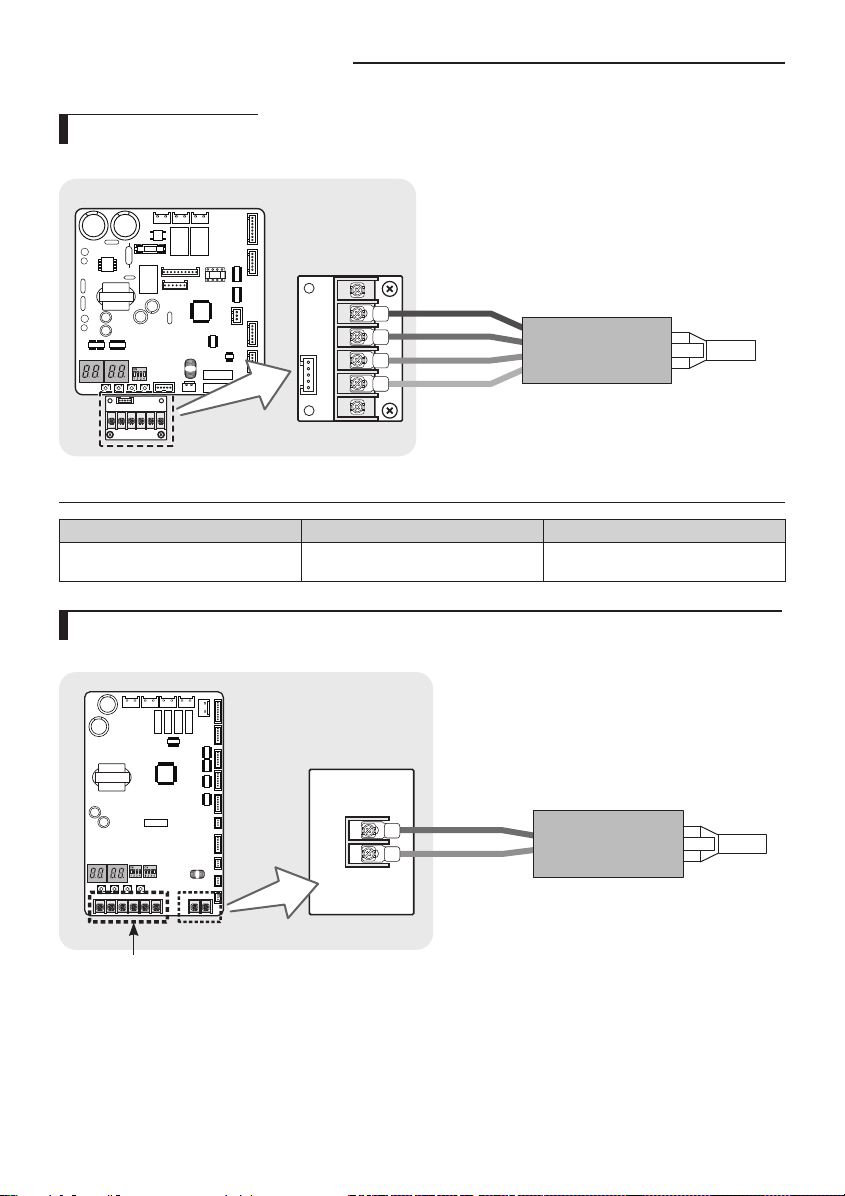
Connecting the cable
DRED wiring diagram
Outdoor unit
ASSY Control out
DRED SUB PBA
COMMON
DRM3
DRM2
DRM1
DRED Controller
Cable specication
Model Power cable Interconnection cable
RC100/125/140/155DHXEG, RC180DHXGG DRED Connected Wire
2, 0.75mm
(Only for reference)
2
H05RN-F (60245 IEC57)
Silence mode controller wiring diagram (ACHCAH/ACJXADH/AC100JXADEH1)
Outdoor unit
Silence Mode Controller
ASSY Control out
European models are not applied.
(ACHCAH/ACJXADH/AC100JXADEH1)
16

Wiring Diagram of Connection Cord
1 phase 3 phase
1(L) 2(N)
Indoor Unit
1(L)
2(N)
L1(R)
L2(S)
(AC 380V)
Outdoor Unit
L3(T)
N
Cable tie
Cable clamp
Indoor Power
Main power cable
1(L)
2(N)
1(L) 2(N)
Indoor Unit
L
N
Cable tie
Cable clamp
Outdoor Unit
F2
F1
Communication
cable
Indoor Power
3 Phase 4 Wires power cable
• Lay the electrical wiring so that the front cover does not rise up when doing wiring work and attach the
NOTE
front cover securely.
• Ground wire for the indoor unit and outdoor unit connection cable must be clamped to a soft copper
tin-plated eyelet terminal with M4 screw hole(NOT SUPPLIED WITH UNIT ACCESSORIES).
Connecting the Power Terminal
Connect the cables to the terminal board using the compressed ring terminal.
Cover a solderless ring terminal and a connector part of the power cable and then connect it.
Silver solder
F2
F1
F2F1
Communication
cable
ENGLISH
Nominal
dimensions
for cable
[mm2(inch2)]
(0.006/ 0.009)
Nominal
dimensions
Standard
for screw
dimension
[mm(inch)]
[mm(inch)]
4(3/8) 9.5(3/8)
4/6
8(3/16) 15(9/16) 9 (3/8)
10(0.01) 8(3/16) 15(9/16)
16(0.02) 8(3/16) 16(10/16)
8(3/16) 12(1/2)
25(0.03)
8(3/16) 16.5(10/16)
B D d1 E F L d2 t
Allowance
[mm(inch)]
±0.2
(±0.007)
±0.2
(±0.007)
±0.2
(±0.007)
±0.3
(±0.011)
Standard
dimension
[mm(inch)]
5.6(1/4)
7.1(1/4)
9(3/8)
11.5(7/16)
Allowance
[mm(inch)]
+0.3(+0.011)
-0.2(-0.007)
+0.3(+0.011)
-0.2(-0.007)
+0.3(+0.011)
-0.2(-0.007)
+0.5(+0.019)
-0.2(-0.007)
Standard
dimension
[mm(inch)]
3.4(1/8)
4.5(3/16)
5.8(1/4)
7.7(5/16)
Allowance
[mm(inch)]
±0.2
(±0.007)
±0.2
(±0.007)
±0.2
(±0.007)
±0.2
(±0.007)
Min.
[mm
(inch)]
6 (1/4)
7.9
(5/16)
9.5
(5/16)
11
(3/8)
Min.
Max.
[mm
[mm
(inch)]
(inch)]
5
20 (3/4) 4.3 (3/16)
(3/16)
28.5
(1-1/8)
30
9 (3/8)
(1-3/16)
13
33
(1/2)
(1-5/16)
15
(5/8)
34
(1-3/8)
13
(1/2)
Standard
dimension
[mm(inch)]
8.4 (1-3/16)
8.4 (1-3/16)
8.4 (1-3/16)
8.4 (1-3/16)
8.4 (1-3/16)
Allowance
[mm(inch)]
+0.2 (+0.007)
0(0)
+0.4 (+0.015)
0(0)
+0.4 (+0.015)
0(0)
+0.4
(+0.015) 0(0)
+0.4 (+0.015)
0(0)
(inch)]
(0.03)
(0.05)
Min.
[mm
0.9
1.15
(0.04)
1.45
1.7
(0.06)
17
Connecting the cable
Nominal
dimensions
for cable
[mm2(inch2)]
35(0.05)
50(0.07) 8(3/16) 22(7/8)
70(0.10) 8(3/16) 24(1)
Nominal
dimensions
for screw
[mm(inch)]
8(3/16) 16(10/16)
8(3/16) 22(7/8)
B D d1 E F L d2 t
Standard
dimension
[mm(inch)]
Allowance
[mm(inch)]
±0.3
(±0.011)
±0.3
(±0.011)
±0.4
(±0.015)
Standard
dimension
[mm(inch)]
13.3(1/2)
13.5(1/2)
17.5(11/16)
Allowance
[mm(inch)]
+0.5(+0.019)
-0.2(-0.007)
+0.5(+0.019)
-0.2(-0.007)
+0.5(+0.019)
-0.4(-0.015)
Standard
dimension
[mm(inch)]
9.4(3/8)
11.4(7/16)
13.3(1/2)
Allowance
[mm(inch)]
±0.2
(±0.007)
±0.3
(±0.011)
±0.4
(±0.015)
Min.
[mm
(inch)]
12.5
(1/2)
17.5
(11/16)
18.5
(3/4)
Min.
Max.
[mm
[mm
(inch)]
(inch)]
13
(1/2)
(1-1/2)
13
43 (1-
(1/2)
11/16)
14
50 (2) 8.4 (1-3/16)
(9/16)
20
51 (2) 8.4 (1-3/16)
(3/4)
38
Standard
dimension
[mm(inch)]
8.4 (1-3/16)
8.4 (1-3/16)
+0.4 (+0.015)
+ 0.4(+0.015)
+ 0.4(+0.015)
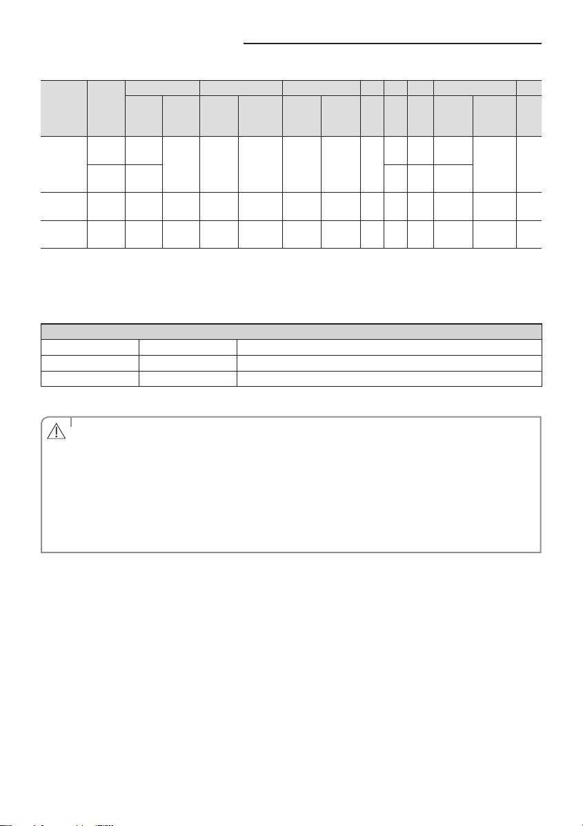
Connect the rated cables only.
Connect using a driver which is able to apply the rated torque to the screws.
If the terminal is loose, re may occur caused by arc. If the terminal is connected too rmly, the terminal may be
damaged.
Tightening Torque (kgf • cm)
M3
M4
M5
5.0~7.5 Communication : F1, F2
12.0~18.0 3phase AC power : 1(L), 2(N), L1(R), L2(S), L3(T), N
20.0~30.0 1phase AC power : 1(L), 2(N), L, N
1N · m = 10 kgf · cm
• When connecting cables, you can connect the cables to the electrical part or connect them through the holes
below depending on the spot.
CAUTION
• Run transmission wiring between the indoor and outdoor units through a conduit to protect against
external forces, and feed the conduit through the wall together with rergerant piping.
• Remove all burrs at the edge of the knock-out hole and secure the cable to the outdoor knock-out using lining
and bushing with an electrical insulation such as rubber and so on.
• Must keep the cable in a protection tube.
• Keep distances of 50mm or more between power cable and communication cable.
• When the cables are connected through the hole, remove the Plate bottom.
Allowance
[mm(inch)]
0(0)
0(0)
0(0)
Min.
[mm
(inch)]
1.8
(0.07)
1.8
(0.07)
2.0
(0.078)
18
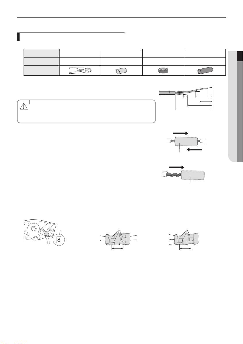
How to connect your extended power cables
1. Prepare the following tools.
Tools Crimping pliers Connection sleeve (mm) Insulation tape Contraction tube (mm)
Spec MH-14 20xØ6.5(HxOD) Width 19mm 70xØ8.0(LxOD)
Shape
ENGLISH
2. As shown in the gure, peel o the shields from the rubber and wire of the
power cable.
- Peel o 20 mm of the wire shields of the tube.
• After peeling o the tube wire, you must insert a contraction tube.
CAUTION
• For information about the power cable specications for indoor and
outdoor units, refer to the installation manual.
Power cable
202020
60
120
180
(Unit: mm)
3. Insert both sides of core wire of the power cable into the connection sleeve.
Method 1
Push the core wire into the sleeve from both sides.
Connection sleeve
Method 2
Twist the wire cores together and push it into the sleeve.
Connection sleeve
4. Using a crimping tool, compress the two points and ip it over and compress another two points in the same location.
- The compression dimension should be 8.0.
- After compressing it, pull both sides of the wire to make sure it is rmly pressed.
Compression
dimension
Method 1
Compress it 4 times.
Method 2
Compress it 4 times.
5 mm
5 mm
19
Connecting the cable
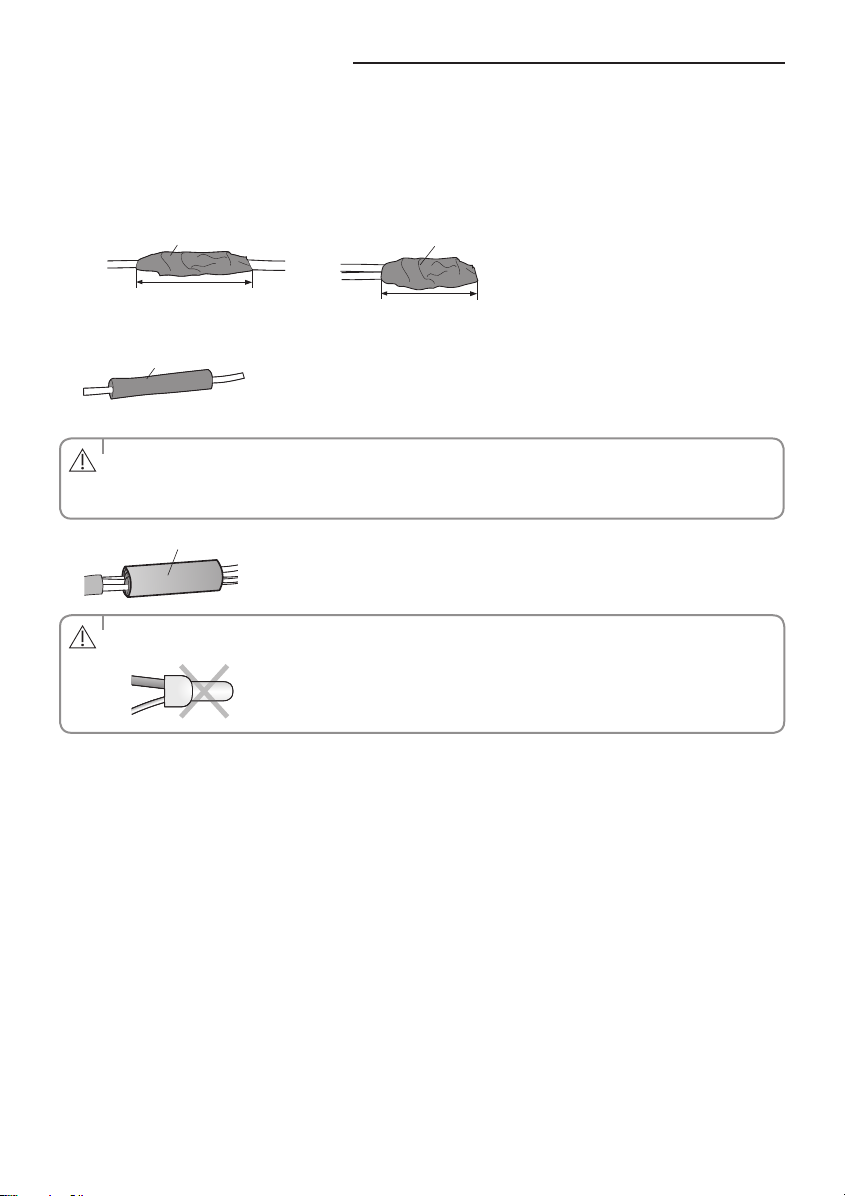
5. Wrap it with the insulation tape twice or more and position your contraction tube in the middle of the insulation tape.
A total of three or more layers of insulation is required.
Method 1
Insulation tape
Method 2
Insulation tape
40 mm
6. Apply heat to the contraction tube to contract it.
Contraction tube
7. After tube contraction work is completed, wrap it with the insulation tape to nish.
• Make sure that the connection parts are not exposed to outside.
CAUTION
• Be sure to use insulation tape and a contraction tube made of approved reinforced insulating materials that have
the same level of withstand voltage with the power cable. (Comply with the local regulations on extensions.)
Insulation tape
• In case of extending the electric wire, please DO NOT use a round-shaped Pressing socket.
WARNING
- Incomplete wire connections can cause electric shock or a re.
35 mm
20
 Loading...