

Samsung RB1955SWRB1955SH, RB1955SW, RB1955SH, RB1955VQ, RB2155SW Service Manual
...
RB1955SW
RB1955SH
RB1955VQ
RB2155SW
RB2155SH
RB2155BB
Model:
Bottom-Mounted Freezer
SAMSUNG Home Appliance Service

2
IMPORTANT SAFETY NOTICE
The service guide is for service men with adequate backgrounds of
electrical, electronic, and mechanical experience. Any attempt to repair a
major appliance may result in personal injury and property damage. The
manufacturer or dealer cannot be responsible for the interpretation of this
informatio
n.
SAMSUNG ELECTRONICS AMERICA, INC.
Technical Service Guide
Copyright ⓒ2004
All rights reserved. This service guide may not be reproduced in whole or in
part in any form without written per mission from the SAMSUNG ELECTRONICS
Company.
WARNING

3
Contents
1. Installation
······································
4
2. Nomenclature
····································
4
3. Product Specifications
·······························
5
4. Electrical part specifications & standard
·····················
5
5. Warranty information
································
7
6. Interior Views and Dimensions
···························
8
7. Refrigeration Cycle and Cool Air Circulation Route
···············
10
8. Mechanical Disassembly
······························
12
9. Operation Function
·································
19
10.
Circuit Descriptions
································
26
11. Diagnostics
·····································
34
12. Illustrated Parts Catalog
·····························
48
13. Safety instruction on services
··························
56
●
Appendix ⅠⅠ(Reference for circuit diagnostics)
·················
57
●
Appendix ⅡⅡ(Circuit diagram)
···························
61

4
1. INSTALLATION
2. NOMENCLATURE
1) T o pr otect refrigerator in movement
Use padded hand truck from side only.
2) Remove all protective tape and pad fr om the refrigerators.
Connect power cord. Adjust the clearance between the doors.
3) Temperature contr ols ar d preset in the factory for
recommended settings.
The refrigerator should runs smoothly and lower the
temperature gradually.
4) Once the refrigerator temperature is sufficiently low
It is recommended to store foods in the refrigerator .
It takes a fe w hours to reach the preset temperatures .
2004 Models
R
B
19
55
SW
/
XAA
Product ; R - REFRIGERATOR
Capacity ; CU. FT
B - BOTTOM MOUNTED FREEZER (BMF)
OPTION ; 55-NO DISPENSER 77-DISPENSER
COLOR ; SW-SNOW WHITE SH-STAINLESS PLATINUM
VQ-BISQUE GLOSSY BB-BLACK
Buyer code
Label Location

5
3. PRODUCT SPECIFICATIONS
4. ELECTRICAL PART SPECIFICATIONS & STANDARD
MK172C-L2U
115V
60HZ
RSCR
R134a
Freol α-10c(Ester), 265cc
Split Fin & Tube Type
Split Fin & Tube Type
Forced & Natural Convection Type
Molecular Sieve XH-9
ID0.82
X
L3000
BSBN(Brass screw)
AC125V 1.4A(SSD-6D)
Condenser
Dryer
Capillary tube
Earth screw
Door switch
Model
Starting type
Refrigerant
Oil Charge
Freezer
Refrigerator
Evaporator
Compressor
RB1955SW/SH/VQ RB2155SW/SH/BB
BMF 2 Door
Electronic control
CYCLO-PENTANE
CYCLO-PENTANE
A.B.S
A.B.S
227
241
32.3X28.3X69.9 32.3X30.3X69.9
Model
Type
Temperature control
Total
Freezer
Refrigerator
Net Capacity
(ft
3
)
Cabinet insulation
Door insulation
Cabinet
Door
Liner
Foam
Net weight(Ib)
Net dimension
(W
XDX
H)
18.7
5.9
12.8
20.4
6.5
13.9
STANDARD
ITEM
Model
Rated Voltage
Frequency
RB1955SW/SH/VQ RB2155SW/SH/BB
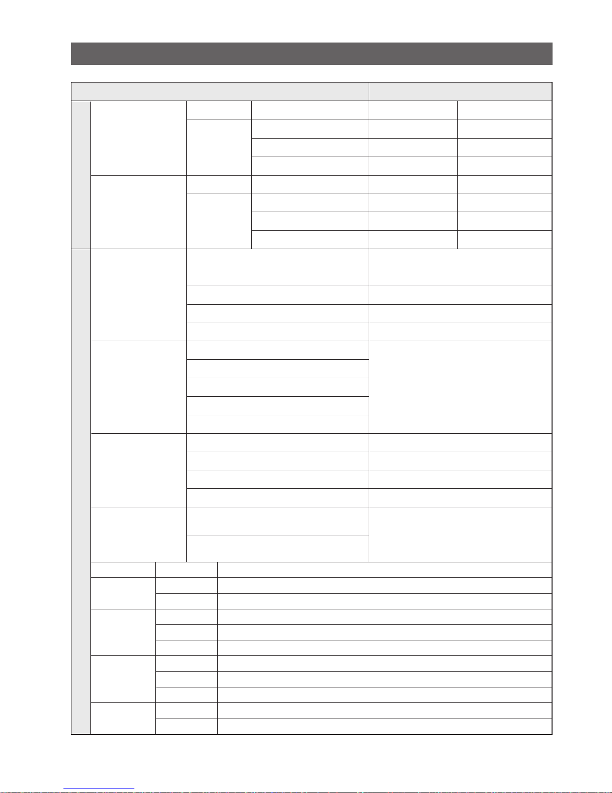
ELECTRICAL PART SPECIFICATIONS & STANDARD
6
RSCR 250VAC, 12㎌
4TM437RHBYY-53
130±5
69±9
J531Q33E100M200-2
10±20%
IS3210-SNP6D
IS3208-SNP6H
IS3208-SCH6A
ITEM STANDARD
Min. 12hrs, Max. 22Hrs
Min. 6hrs, Max. 11Hrs
10±2min
4hr
±
10min
THERMISTOR (502AT), SPEC:5.0K
Ω
AT 77
℉
Freezer
Type
F-Sensor
Type
R-Sensor
ON(℉)
–12.0℉
0℉
10℉
ON(℉)
36℉
42℉
48℉
Temperature Selection
–14℉
–2℉
8℉
Temperature Selection
34℉
40℉
46℉
OFF(℉)
–16.0℉
–4℉
6℉
OFF(℉)
32℉
38℉
44℉
Refrigerator
Defrosting
Sensor
Heater
Fuse
First Defrost Cycle
(Concurrent Defrost of F and R)
Defrost Cycle(FRE)
Defrost Cycle(REF)
Pause Time
Freezer-Sensor
Refrigerator-Sensor
FRE Evap-Sensor
REF Evap-Sensor
Ambient TEMP-Sensor
Defrost Heater(FRE)
Drain Heater(FRE)
Defrost Heater(REF)
Drain Heater(REF)
TemperatureElectrical parts
242W
52W
120W
38W
AC250V 10A 77±5˚C
Thermal-Fuse for preventing
overheating of Freezer Defrost-Heater
Thermal-Fuse for preventing
overheating of Freezer Defrost-Heater
110V-130V/15W
110V-130/30W
Capacitor
Over-Load
Protector
STARTING-
RELA Y
MOT OR-F AN
LAMP
RUNNING
MODEL
TEMP. ON
TEMP. OFF
MODEL
OPERATION
FRE.
REF.
CIRCUIT
FRE
(INCANDESCENT)
REF
(INCANDESCENT)

5. WARRANTY INFORMATION
7

8
• Deli drawer
Pull it out to disassemble.
•
Door Bin
Push it up and slide it out
to disassemble.
• Glass Shelf
Pull it out until its stop
Tilt down and slide it out.
• Ice trays
• Vegetable Drawer
• Gallon Bin
Light
• Freezer Drawer
•
•
•
•
•
•
•
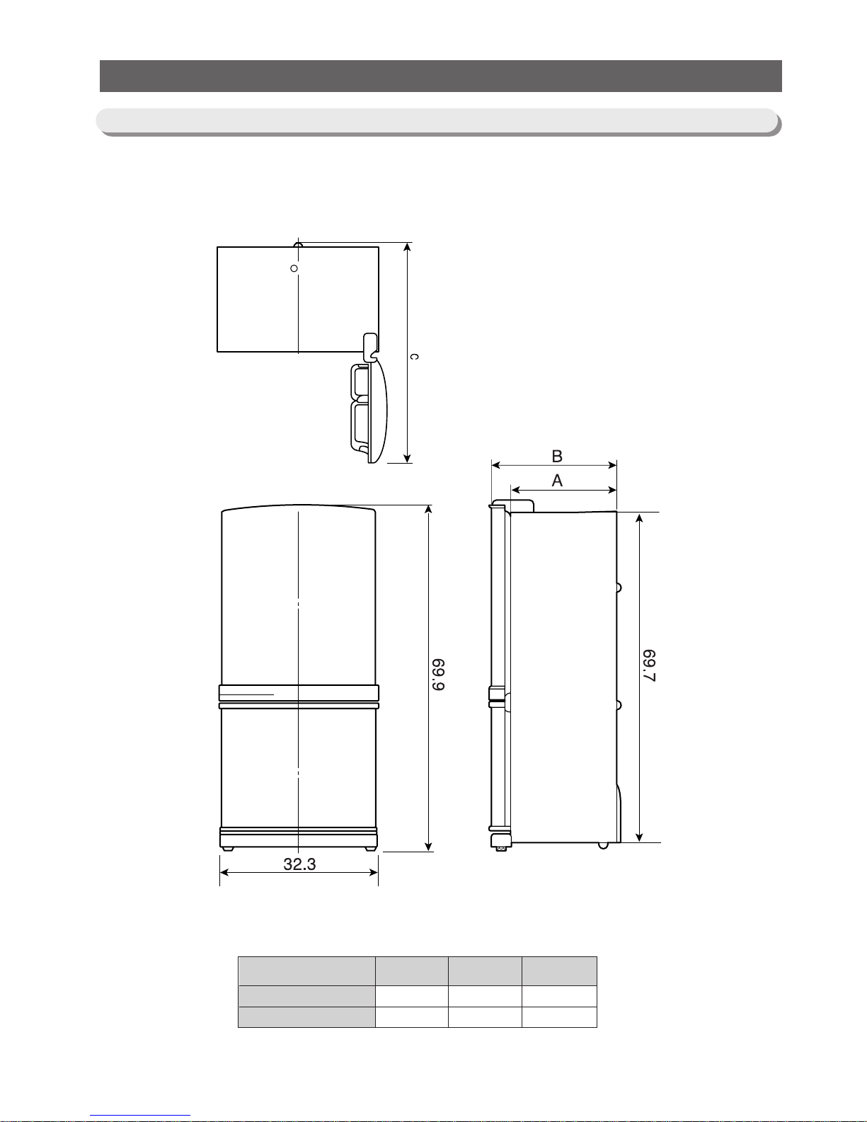
6. Interior Views and Dimensions
6-1) Shelves and Bins
9
Interior Views and Dimensions
MODEL
RB1955
RB2155
A
24.3
26.3
B
28.3
30.3
C
57.8
59.8
6-2) Dimensions of Refrigerator (Inches)

10
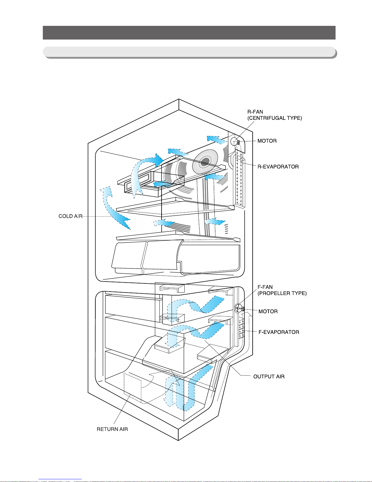
7. Refrigeration Cycle and Cool Air Circulation Route
Compressor → Sub condenser → Cluster pipe → Hot pipe → Dryer → Capillary tube
→ R-Evaporator → F-Evaporator → Accumulator → Suction pipe → Compressor
7-1) Refrigerant Route in Refrigeration cycle
11
Refrigeration Cycle and Cool Air Circulation Route
7-2) Cool Air Circulation

12
8.
Mechanical Disassembly
Refrigerator Disassembly
Control Panel ········································ 13
Refrigerator Light
······································ 14
Freezer Light
········································ 14
Evaporator Cover in the Refrigerator
·························· 15
Evaporator Cover in the Freezer
····························· 16
Evaporator in the Freezer
································· 17
Evaporator in the Refrigerator
······························ 17
Machine Compartment & Electric Box
··························18

13
Mechanical Disassembly
1. Remove the screws.
2. Pull out the control panel.
3. Disconnect the wire connector.
Control Panel

14
Mechanical Disassembly
1. Remove the screw.
2. Remove the lamp cover by unlocking the tabs
and pulling the cover down.
3. Replace the lightbulb by turning it counterclockwise.
4. After replacing the bulb, reattach the cover
and the screw it again.
5. Plug the power cord in and check the lamp by
pressing the R-door switch.
Always unplug the power cord before replacing the refrigerator lamp.
There is the danger of electric shock.
1. Remove the cover by pressing the bottom tab.
2. Replace the lightbulb by turning it counter-clock
wise.
3. Reattach the cover and check the lamp by
pressing door switch.
Warning
Refrigerator Light
Freezer Light

15
Mechanical Disassembly
1. Remove all shelves and drawers from the
refrigerator.
2. Pull out the screw caps with a small flat-blade
screwdriver.
3. Remove 6 Phillps screws from the cover.
4. Unlock the 2 tabs with a flat-blade screwdriver
on each side of the bottom cover.
5. Remove the evaporator cover by pulling out
from the bottom of the evaporator cover.
Evaporator Cover in the Refrigerator
6. Disconnect the wire connector.
■Ductwork of the evaporator fan assembly.

16
6. Remove 2 screws from the rear cover of the
freezer evaporator and unlock the tabs to
remove it.
Mechanical Disassembly
1.
Remove all drawers from the freezer.
2. Remove screws (2) from the support rail.
3. Pull down the holder of the support rail and
disconnect the wire connector to remove it.
4. Unlock the tabs around the evaporator cover
from the buttom.
5. Disconnect wire connector from the top-left
corner.
2 screws
①
①
②
③
②
Evaporator Cover in Freezer

Mechanical Disassembly
17
Evaporator in Freezer
Accumulator
Thermistor
Thermal
Fuse
Evaporator is located in the bottom of freezer to
produce cold air driven across the evaporator coils.
1. Take off the ductwork in Freezer.
2. Disconnect the wire connector (Heater,
Bimental, and Thermistor).
3. Desolder the inlet and outlet tubes.
4. Remove the evaporator.
5. Take the same steps to seal the system as
mentioned earlier.
Evaporator is located in the bottom of refrigerator.
1. Take off the ductwork in refrigerator.
2. Disconnect the wire connector.(Heater and
Thermistor)
3. Desolder the capillary tube and the suction line
from the evaporator.
4. Remove the evaporator.
5. With a file, score the capillary tube just
upstream of the soldered point. Break off the
soldered section to help prevent solder from
plugging the tube during soldering.
6. Place a new evaporator and braze the suction
and capillary tube to evaporator using silver
solder.
7. Install a replacement dryer.
8. Evacuate and recharge the system using
reasonable procedures.
Evaporator in Refrigerator
Thermal
Fuse
Thermistor

18
1. Unplug the power cord.
5. Electric box assembly
Make sure the power cord is
unplugged before replacing any
electric components.
Mechanical Disassembly
2. Remove the screws of the compartment cover.
Slide it up and take out from the refrigerator.
3. Mechine compartment assembly
Machine Compartment &&Electric Box
Warning
4. Disassemble the electric box cover after
removing the screws with a Phillips screwdriver.

9. Operation Function
19
9-1) Digital Panel ···································20
9-2) Temperature Control Function
·························20
9-3) Power Freeze and Power cool Functions
··················· 20
9-4) Sound Function
································· 21
9-5) Defrost Function
································· 21
9-6) Forced Operation Function
··························· 22
9-7) Power failure compensating Function
····················· 23
9-8) Exhibition Function
······························· 23
9-9) Self - Diagnostics Function
··························· 23
9-10) Component Load Operation Function.
···················· 24
9-11) C-Fan Motor Delay function
·························· 25
 Loading...