

WF-R1061/YLP
R861/YLP
SERVICE
Manual
WF-R1061
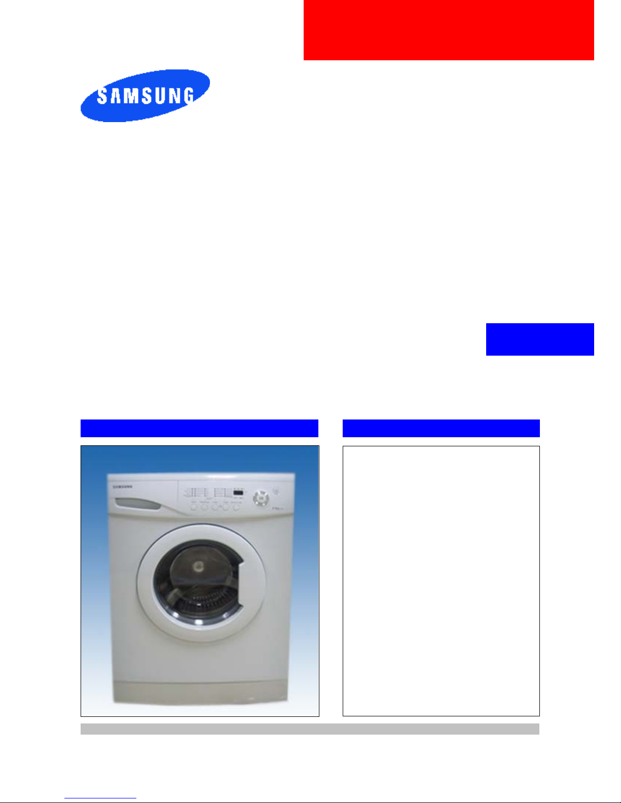
THE FEATURE OF PRODUCT
1. Delay start
2. Coloureds
3. Hand wash
4. Prewash
5. Quick wash
Refer to the service manual in the itself (http://itself.sec.samsung.co.kr/) for the more information.
BASIC MODEL
WF-F1061
WASHING MACHINE

CONTENTS
1. PRECAUTIONS
1-1. SAFE PRECAUTIONS .......................................................................................................................................... 1
1-2. PRECAUTIONS UPON INSTALLATION ................................................................................................................ 2
2. THE FEATURE OF PRODUCT
2-1. SPECIFICATIONS .................................................................................................................................................. 5
2-2. OVERVIEW OF THE WASHING MACHINE .......................................................................................................... 6
2-3. THE COMPARATIVE SPECIFICATIONS OF PRODUCT ...................................................................................... 7
3. PRODUCT SPECIFICATIONS
3-1. OVERVIEW OF THE CONTROL PANEL ............................................................................................................... 8
3-2. PROGRAMME CHART .......................................................................................................................................... 9
3-3. MAIN FUNCTION ................................................................................................................................................. 11
3-4. TECHNICAL POINT .............................................................................................................................................13
3-5. DESIGNATION OF MAIN COMPONENTS .......................................................................................................... 16
4. ALIGNMENT AND ADJUSTMENTS
4-1. GENERAL ERROR FUNCTION ........................................................................................................................... 19
4-2. TEST MODE ......................................................................................................................................................... 21
5. ASSEMBLY AND DISASSEMBLY
5-1. TOOLS FOR DISASSEMBLY AND ASSEMBLY .................................................................................................. 22
5-2. ASSEMBLY AND DISASSEMBLY ........................................................................................................................23
6. TROUBLE DIAGNOSIS5
6-1. TROUBLE DIAGNOSIS ........................................................................................................................................ 32
6-2. PROBLEM CHECKING AND METHOD OF PCB ................................................................................................. 34
6-3. DETAILED DIAGNOSIS ....................................................................................................................................... 40
7. EXPLODED VIEWS AND PARTS LIST
7-1. EXPLODED VIEWS OF TOP(FRONT) ................................................................................................................ 41
7-2. EXPLODED VIEWS OF TUB ............................................................................................................................... 42
7-3. EXPLODED VIEWS OF CASE ............................................................................................................................ 43
7-4. PARTS LIST ......................................................................................................................................................... 44

CONTENTS
8. BLOCK DIAGRAM ...................................................................................................................................47
9. WIRING DIAGRAM
9-1. PCB ASSY’ LAYOUT ............................................................................................................................................ 48
9-2.CONNECTOR & RELAY TERMINALS DESCRIPTION (MAIN PCB) .................................................................... 49
10. SCHEMATIC-DIAGRAM
10-1. EMZ (WF-R1061) ............................................................................................................................................... 50
11. PCB CIRCUIT DIAGRAM
11-1. PCB CIRCUIT DIAGRAM ................................................................................................................................... 51
12. CIRCUIT DESCRIPTION
12-1. OVERALL SYSTEM ........................................................................................................................................... 52
12-2. AC INPUT & POWER CIRCUIT ......................................................................................................................... 53
12-3. DRIVING SYSTEM CIRCUIT ............................................................................................................................ 54
12-4. MOTOR CIRCUIT .............................................................................................................................................. 55
12-5. SENSOR DETECTION CIRCUIT ...................................................................................................................... 56
12-6. MOTOR TACHO INPUT SYSTEM ....................................................................................................................57
13. REFERENCE INFORMATION
13-1. MODEL NAME ...................................................................................................................................................58
13-2. TERMINOLOGY ................................................................................................................................................. 59
13-3. FABRIC CARE CHART ...................................................................................................................................... 60
13-4. ELECTRICAL WARNINGS ................................................................................................................................. 60
13-5. Q & A .................................................................................................................................................................. 61

1
1. Precautions
1-1. Safe Precautions
1. Do not allow the customer to repair the product.
It may cause personal injury or product damage when the unit is serviced by unqualifi ed personnel.
2. Disconnect power to the appliance before servicing.
Be aware of the possibilities of an electric shock.
3. Do not use multi-plug.
Power outlet may be overloaded causing the socket to overheat.
4. Check for any damage on power plug or power outlet.
Replace it immediately if it has problem. (It may cause an electric shock or fi re)
5. Make sure to earth the product.
May cause electric shock.
6. Do not clean the product with water.
May cause electric shock / fi re or shorten product life.
7. The wiring harness should be free from moisture and connected properly during serving.
It should be proof against any external force.
8. Remove any dust or dirt in the product, wiring section and connections during servicing.
Protect against possibilities of fi re due to tracking etc.
9. Check for any water trace on electrical parts, harness, etc.
Replace the parts or wipe dry the water.
10.Check the assembled status of the parts after servicing.
Check if the product is assembled in the same status as before servicing.
11.Be sure not to pull on the power cord but to unplug it by holding the plug.
Beware of possibility of electric shock or fi re when the power cord is damaged.
12.Unplug the power plug from the outlet when the washing machine is not used.
Beware of possibility of electric shock or fi re while lightening.
13.Do not use or put fl ammable materials (including gasoline, alcohol, thinner etc) around the
washing machine.
Flammable materials may spark an explosion or fi re.
14.Do not put a water containing bowl or wet laundry on the washing machine.
It may cause an electric shock or fi re, or shorten the product life when its water penetrates into the
washing machine.
15.Do not install the washing machine in a place where it is exposed to snow or rain etc.
It may cause an electric shock or fi re and shorten the product life.
16.Do not press control buttons with pointed objects such as pins, needles, etc.
It may cause an electric shock or other problems.
17.Check the washing machine is leveled horizontally on the fl oor and is installed properly.
Vibration may shorten the product life.
18.Make sure to use connectors when connecting wires.
If wires are connected without connectors, it may cause a tracking fi re.
19.When the washing machine is to be laid down for servicing, put a pad on the fl oor and lay the product
on its side slowly.
If the wash machine is laid on its front, internal components may be damaged by the tub.
2
1-2. Precautions upon Installation
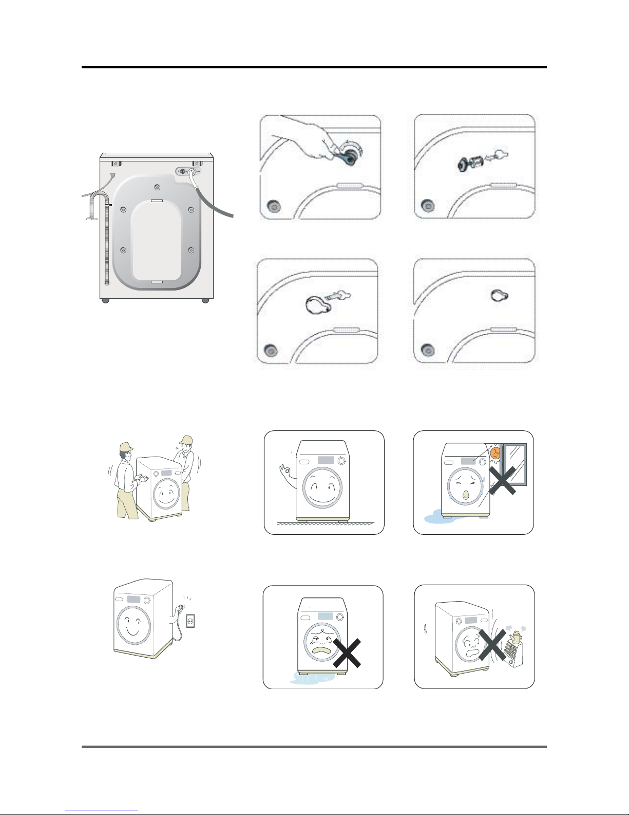
■ How to Remove Shipping Bolts
1. Remove the screws by using
the supplied spanner.
2. Remove the shipping bolts
from the back of the unit.
3. Fill the holes with the
supplied plastic caps.
4. Keep the shipping bolts and
screws for future use.
■ Precautions before Installation
The unit is quite heavy. So,
make sure to have 2 or more
personnel move it.
Install the unit at a place with
a wall outlet easily accessible.
Make sure that the unit stands
on a fi rm and leveled fl oor.
keep it away from direct sunlight
or high humidity, and install it in
a place with good ventilation.
Keep the unit away from places in
which it is freezing, especially in
winter.
Keep the unit away from heat
appliances such as a heater.
3
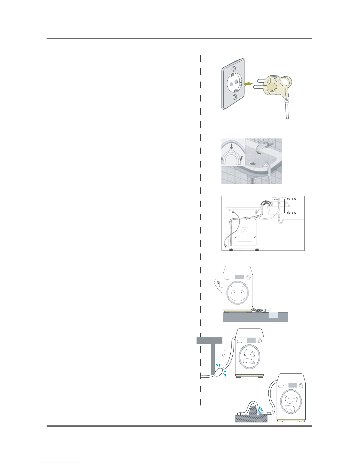
■ Grounding
Ć Make sure to ground the unit to prevent electric leak
age or shock.
Ć With a grounded receptacle
It does not need an additional grounding.
■ Water Drainage
Ć Hook the drain hose over the Wash Basin or Laundry
Tub or plug the end of the drai hose into the Standpipe.
- Hook the drain hose over the Wash Basin or
Laundry Tub or plug the end of the drain hose
into the Standpipe.
- The outlet end of the drain hose must be at
least 60-90 cm above the base of the machine.
Ć Seal the drain pipe connections.
- If not, it may cause water leakage.
Ć Prevent water from siphoning away.
- If the end of the drain hose is put in water,
it could siphon away water during washing.
So, make sure that the end of the drain hose
is not put in water.
Note: Caution must always be exercised to
avoid collapsing or damaging the drain hose.
For best performance the drain hose should
not be restricted in any way, through elbows,
couplings or excessive lengths.
4
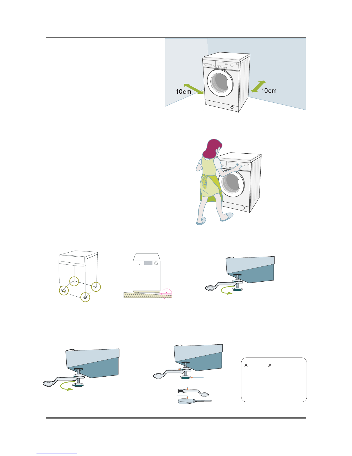
Ca
uti
utionon
Tighten the lock nut after
the leveling. If not, it
could generate vibrations &
noises.
Lock Nut
Leveling Bolt
Spanner
Flat Head
Screwdriver
■ How to Level the Unit
1.Select an installation place.
Install the unit with 10cm or more
clearance from its surrounding walls.
2.Check if the unit is leveled.
If the unit wabbles, adjust the leveling
legs.
3.Adjust the leveling legs.
The 4 leveling legs should touch the
fl oor all together.
When the unit is not leveled
Lift up the unit a little bit and adjust the shortest.
Turn the leveling bolt counter clockwise as shown in the picture above
(The leveling leg gets longer.)
After adjusting the leveling bolt, tighten the
lock nut by turning it clockwise.
5
2. THE FEATURE OF PRODUCT
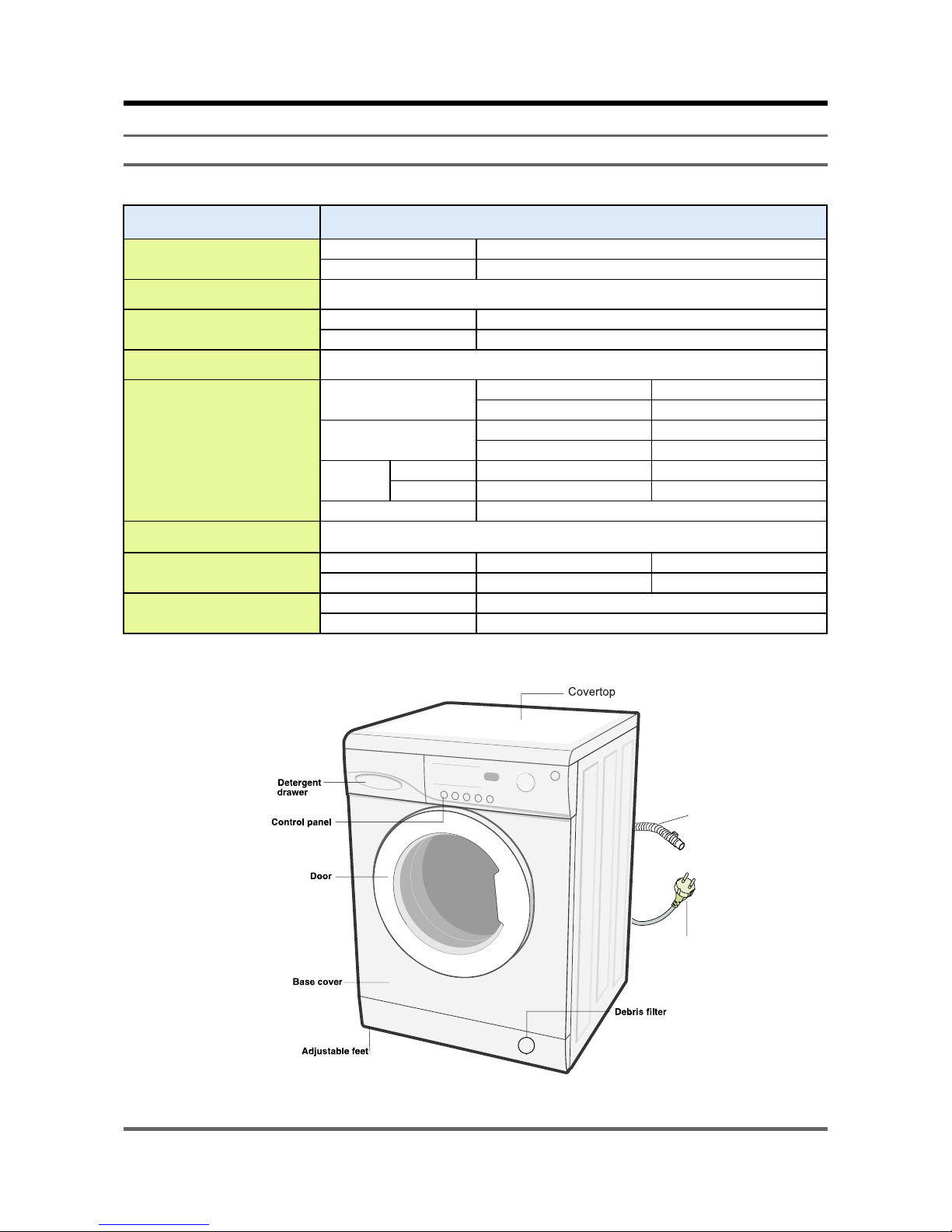
2-1. SPECIFICATIONS
WASH TYPE FRONT LOADING TYPE
DIMENSION
NET W 598mm X D 450mm X H 844mm
GROSS W 668mm X D 576mm X H 890mm
WATER PRESSURE 50 kPa ~ 800 kPa
WEIGHT
NET 66 kg
GROSS 69 kg
WASH and SPIN CAPACITY 5.2 kg (DRY LAUNDRY)
POWER CONSUMPTION
WASHING
220V 180W
240V 180W
WASHING
AND HEATING
220V 1800W
240V 2100W
SPIN
MODEL WF-R1061 WF-R861
220~240V 500W 430W
PUMPING 34 w
WATER CONSUMPTION 49ℓ(STANDARD COURSE)
SPIN REVOLUTION
MODEL WF-R1061 WF-R861
rpm 1000 800
PACKAGE Wt
PAPER 2.1kg
PLASTIC 0.9kg
Plug
Drain Hose
6
2-2. OVERVIEW OF THE WASHING MACHINE
OPTION
7
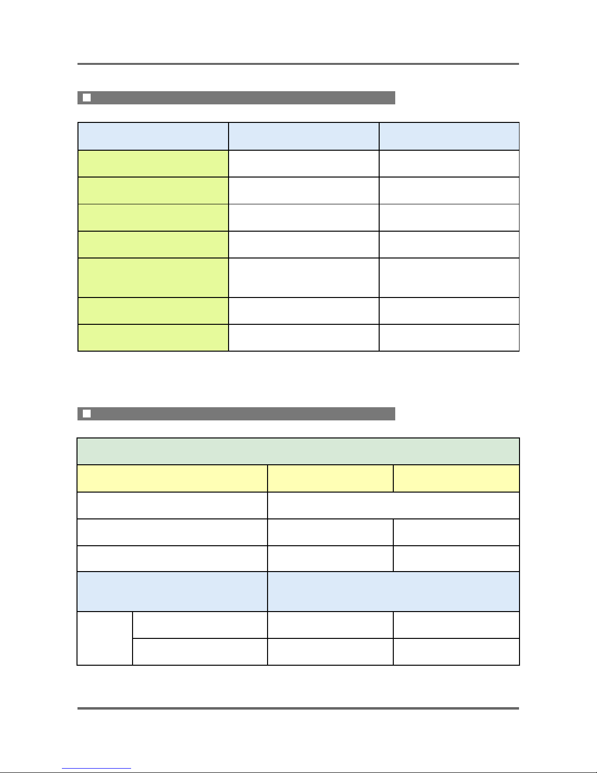
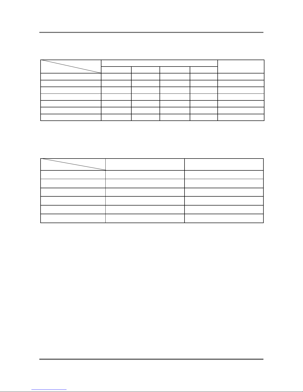
2-3. THE COMPARATIVE SPECIFICATIONS OF PRODUCT
Item 5.2kg Old (4.5kg)
Model Name WF-R1061 WF-F1061
Capacity (Washing) 5.2kg 4.5kg
Drum Capacity 49ℓ 43ℓ
Washing Motor HXGN2I HXGN2I
Supply/Drain All temperatures /Drain pump All temperatures /Drain pump
Balancer Weight Weight
SIZE(W*D*H) 598*450*890 598*404*890
5.2kg
Model Name WF-R1061 WF-R861
Function
Water-level Control O O
Add Laundry X X
Exterior Replacement
Part Name
Specifi cations
Design
Cover Door
Neat-white Neat-white
Handle Door
Neat-white Neat-white
THE COMPARATIVE SPECIFICATIONS OF PRODUCT˄ϔ˅
THE COMPARATIVE SPECIFICATIONS OF PRODUCT˄Ѡ˅
8
3. PRODUCT SPECIFICATIONS
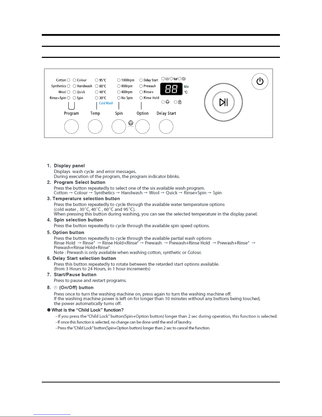
3-1. OVERVIEW OF THE CONTROL PANEL
9
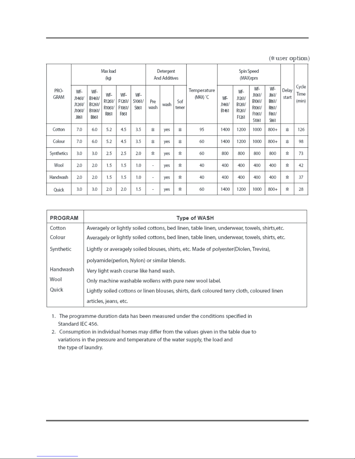
3-2. PROGRAMME CHART
10
3-3. MAIN FUNCTION
1) Auto power S/W off function
● After power on, the auto power S/W off function automatically switches power off for you if you do not
press selection button for 10 minutes
● After selecting the function, the auto power S/W off function automatically switches power off for you if
you do not press start/pause button for 10 minutes
● until 5 minutes past, After fi nishing the last function, the auto power S/W off function automatically
switches power off for you if you do not re-select the course button or manual button
2) Door open function
● Door just can be opened at water level 24.80 KHz over, water temperature 55ć below, motor off, if
power is off door is not opened (only auto-door model)
● If door is open during the operating, all operating is halted, and door error message will be displayed
(2-digit panel displays “dE” 4-digit panel displays “door”) and error melody will coming out
● Door open error can be cleared by closing the door. the operating keeps going on
3) Rinse hold function
● If rinse hold function selected, the operating is fi nished , the machine do not drain the water after last
rinse
4) No spin function
● If no spin function selected, the operating is fi nished after last rinse
5) Drain function
● Drain function is over, after pumping out the water for 2 minutes , without motor rotating
6) Pre-washing function
● Pre-washing function can be selected ,when you choice the following mode; cotton, coloreds, syn
thetics, delicates, baby cotton, baby coloreds, baby delicates, baby stains
● Water level/reverse time is the same with the selected course
● Pre-washing takes about 16 minutes
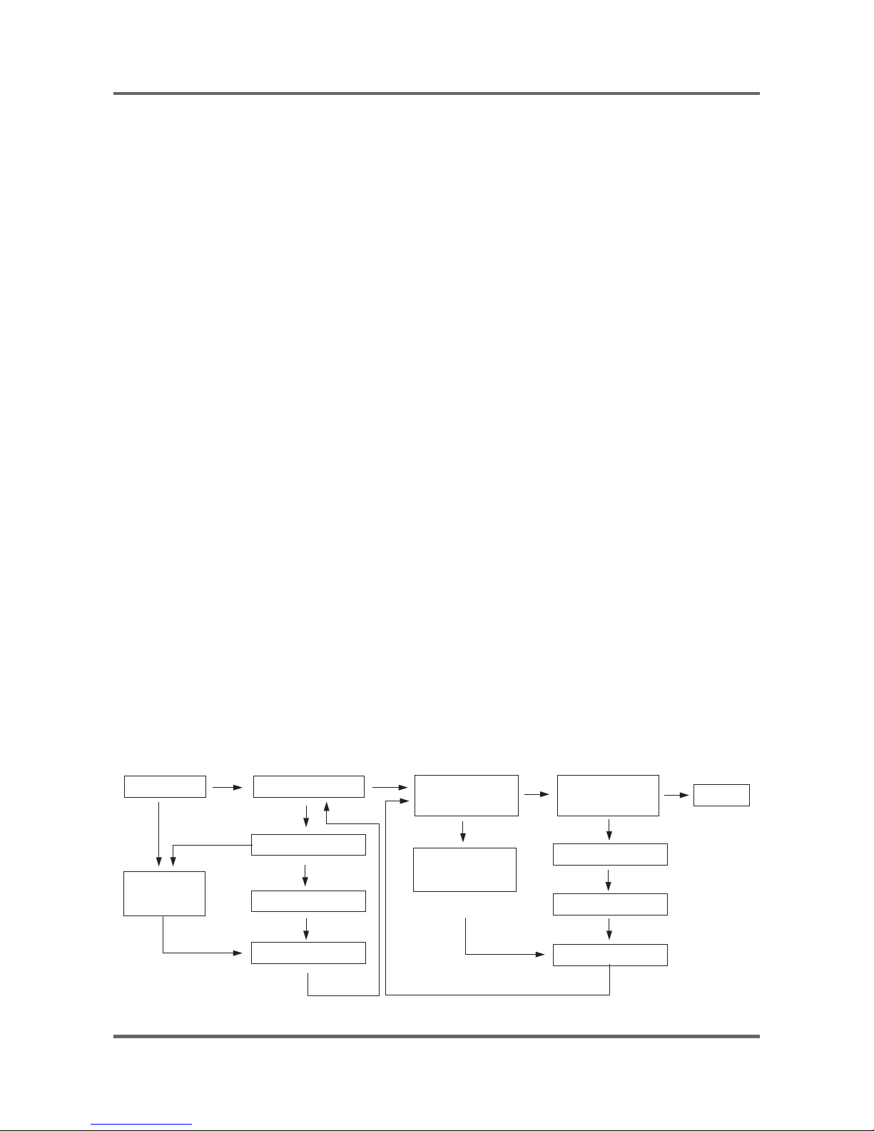
7) Power-out compensation function
● If power is out on selected process, the process before power out is stored to EEPROM, once power is
back the process before power out continues.
● When power is back, washing process starts from the process at the point of the power out, rinse/drain
process starts from the initial process.
POWER-OUT COMPENSATION FUNCTION PROCESS
START WASHING
RINSE/DRAIN
START
FINISH
POWER OUT
POWER BACK
MICOM RESTORE
POWER OUT
POWER BACK
MICOM RESTORE
SAVE DATA
to EEPROM
SAVE DATA
to EEPROM
RINSE/DRAIN
PROCESS
11
8) Fuzzy washing function (weight-sensing)
● After fi nishing initial water supply, when the fall of the water level needs supplementary water supply,
Sensing function perceives the weight with the supplementary water supply numbers and starts to
work. Under the course of Cotton, or Coloureds, if the supplementary water supply numbers become
over 2 times the function is going at default condition ( high water level ), if 1 time that is going at
middle level, if 0 below low water level, heating hours and rinse hours depend on the above data.
ECO PRE mode is selected, the process going on at default condition.
Washing hours
Rinse water level
Cotton Coloureds
High Default Default Default
Middle Default-20 min Default-10min 23.80KHZ
Low Default-30 min Default-15min 24.10KHZ
ĆAfter sensing weight, above hours is decreased from above default hours
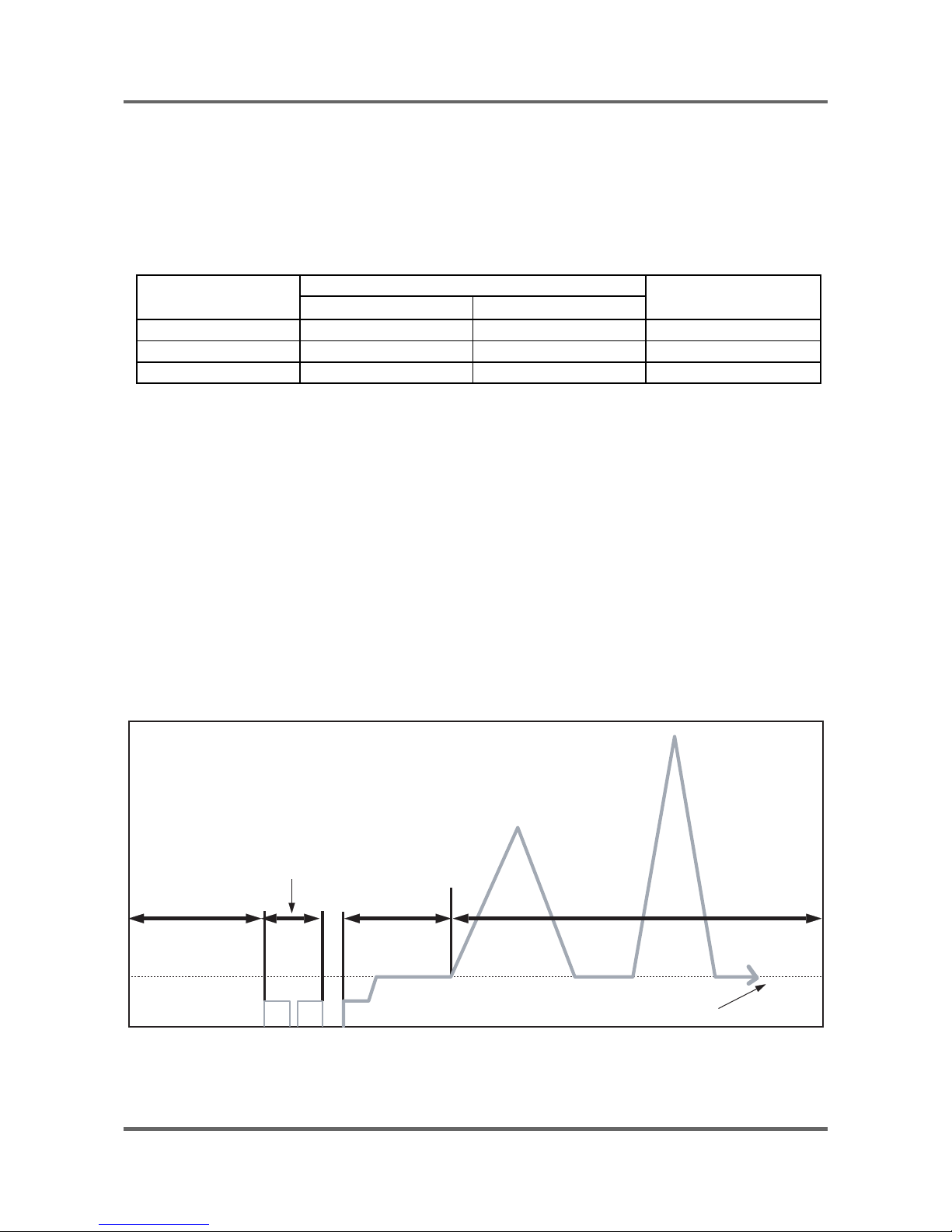
9) Bubble - detecting function
At the each condition of washing&dehydrating , rinse&dehydrating , hydrating, bubble -detecting function
works, this function works 5times normally, if the function detects bubbles at 6 times , the bubble-detecting function
stops and go on to the next process.
● The bubble-detecting function during washing & dehydrating to rinse & dehydrating
after 2 times instant dehydrating and before main dehydrating, if the water level is under 24.50KHZ,
Bubble
→ Detecting function thinks there are bubbles and add the bubbles-removing rinse, needing
hours are above hours and 8 Min 40 sec.
→ The bubble-detecting function during single hydrating process
after 2 times instant dehydrating and before main dehydrating , if the water level is 24.50KHZ below or
during main dehydrating, water level data is 24.50KHZ below Bubble-detecting function thinks there are
bubbles and add the bubbles-removing rinse 1 times, needing hours are above hours and 5 min 50 sec.
draining &reverse
50 sec
unbalance
detecting range
18 sec
laundry scattering
bubble detection
(default water level 24.50KHZ below)
220rpm
Bubble-detecting function operating process
500rpm
12
10) Unbalance detecting & laundry balance positioning system
ķ Just before the hydrating process and just after reversal rotation for balancing laundry position, this
function is carried out
ĸThe initial 6 sec is the period of reversal rotation for balancing laundry position , Drum rotates 50rpm
for initial 6 sec
Ĺ Next 12 sec, the rotation increases the speed from 50 rpm to 95 rpm slowly
ĺ During the next 8 sec, drum rotates at the speed of 95 rpm, the sensor decides the degree of laundry
unbalance with TACHO data which is attached to motor
Ļ If the degree of unbalanced laundry is over 6 times to default value, laundry balancing system carryies
out feed back process 3 times.
unbalance
detecting range
20 sec
laundry scattering
210rpm
490rpm
500rpm
220rpm
95rpm
Unbalance detecting & laundry balance positioning system
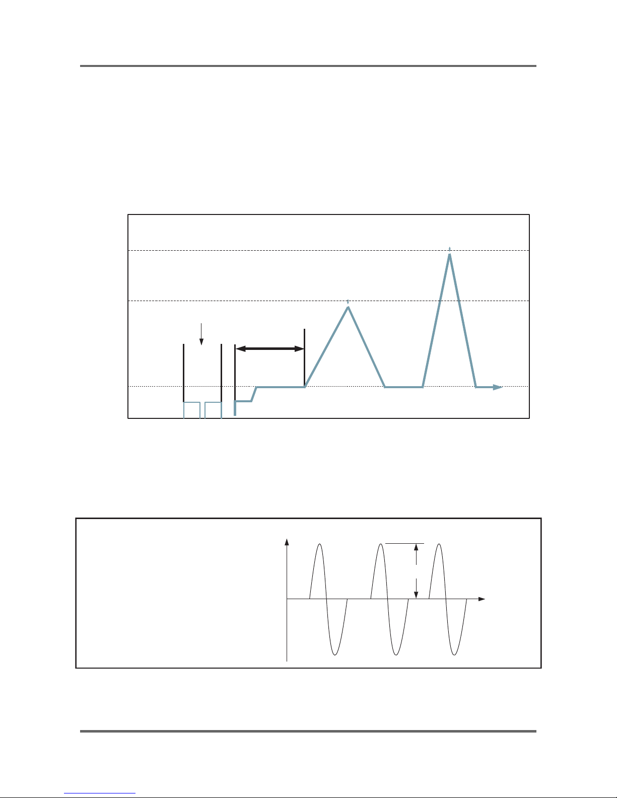
11) R.P.M control
The rotating motor enables the magnetics( i.e generator) to generate magnetic fl ux in proportion to
r.p.m, magnetic fl ux induced by coil sensor in the opposite side produces the wave like the fi gure below
to dΦ/dt and via rectangular wave generating circuit, the waves reaches MICOM and micom controls
r.p.m with the pulse, count and cycle inputted by program.
Vp
T (HOUR)
<COIL electrical wave at both ends>
V (VOLT)
13
3-4. TECHNICAL POINT
1) Motor on/off time at each course
unit:sec
Course
Model
Washing
Motor r.p.m
Cw Off Ccw Off
Cotton 13 4 13 4 50
Coloureds 12 8 12 8 50
Synthetics 7878 40
Wool 2 48 2 48 50
Handwash 2 58 2 58 50
Quick 12 8 12 8 50
Pre 10 10 10 10 50
2) Final dehydrating r.p.m at each course
unit:rpm
Model
Course
WF-R1061 WF-R861
Cotton 1000 800
Coloureds 1000 800
Synthetics 800 800
Wool 400 400
Quick 1000 800
Handwash 400 400
Ć You can change the r.p.m to the above a table by use spin button under no spin situation.
14
3) The water supply control at each process cycle
Model
Process cycle
WF-R1061,WF-R861
Pre Washing Cold water 5L/min
Washing Cold water 10L/min + (Hot water 10L/min)
Rinse Cold water 10L/min
Final rinse Cold water 10L/min + Cold water 5L/min
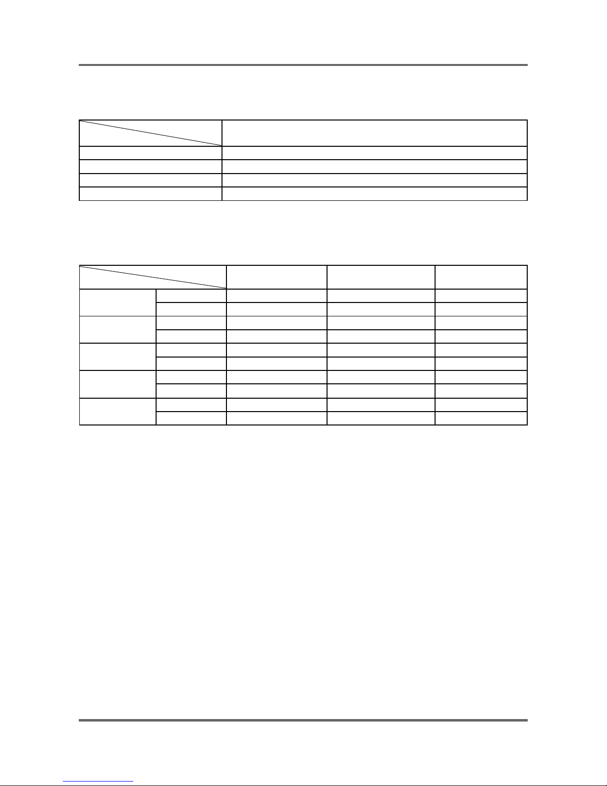
4) The water level data at each course
unit:Khz
Model
Course
Default water level
(kHz)
Supplementary water
START (kHz)
Supplementary water
End (kHz)
Normal
Washing 24.60 25.00 24.80
Rinse 23.60 24.50 24.20
Colours
Washing 24.60 25.00 24.80
Rinse 23.60 24.50 24.20
Synthetics
Washing 23.80 25.00 24.30
Rinse 23.65 24.55 24.30
Wools /Hand-
wash
Washing 23.45 24.35 24.00
Rinse 23.15 24.35 24.00
Quick
Washing 24.40 25.00 24.70
Rinse 23.80 25.00 24.70
15
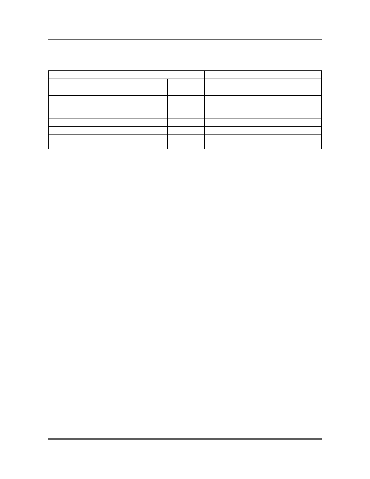
5) The other water level data
unit:Khz
The water data unter each conditon WF-R1061,WF-R861
1st water supply (only preparation) 25.50 1st water supply level to washing tub
Overfl ow error 21.50 The water supplied reach 2/3 of door
Bubble
detectingatwashing/rinse/dehydrating
24.50 Bubble -detecting water level
Bubble detecting rinse water level 23.00 The water level which can detect bubbles
Water level which can open door 24.80 over It is possible to open the door
Water level which can drive heater 25.50 Safety water level of wash heater
Water level which can reset the drain 25.50 The water level can be detected after 1st drain-
ing
ĆIf water level is 15KHZ below or 30 KHZ above , Sensor-pressure is out of order so needs changing.

16
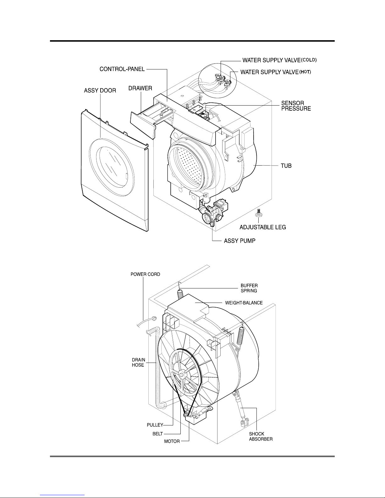
3-5. DESIGNATION OF MAIN COMPONENTS
3-5-1. Normal / Reverse Revolution of Motor and R. P. M. Control
+
-
89
510
Rotor
Stator coil
CW
+
-
89
5
5
10
Rotor
Stator coil
CCW
<Figure1> <Figure2>
123456
789
10
STATOR
WASHING MOTOR
T
A
C
H
O
H
I
G
H
-
S
P
E
E
D
S
T
A
T
O
R
P
R
O
T
E
C
T
O
R
M
I
D
D
L
E
-
S
P
E
E
D
R
O
T
O
R
(
1
5
0
C
)
H
(± 7%)
STATOR(5.1)
STA
TOR(5.10)
ROTOR(8.9) TACHO(3.4)
PROTEC
TOR(6.7)
“H”(mm) Code-No. Remark
Resist
ancevalue
2.07Ω 0.90Ω 1.99Ω 38.8Ω 0 39
DC31-
00002E
WF-R1061
WF-R861
Rated
value
220~240V/50Hz
3-5-2. Door safety Device
When Door is closed, door stay closed. if “set” is operated, power supplied to ,wires have solenoid or bimetal keep the
door closed, and electronical power fl ows between and make it operate.
DC64-00653A ( EMZ )
17
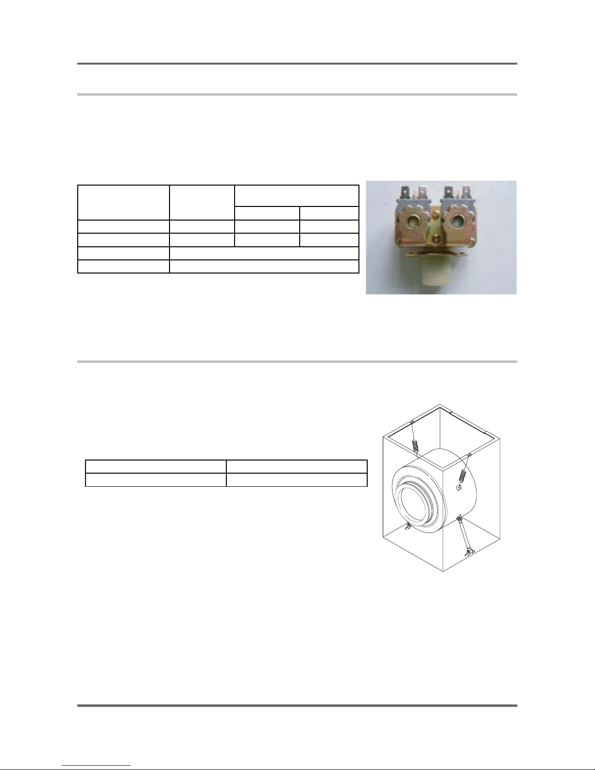
3-5-3. Detergent tub and water supply value
A Detergent tub is composed of housing and 3 drawers . supplied water fl ows into the 3 drawer-detergent
tub by way of classifi er at each washing process.
three open drainage way with detergent and supplied water by way of connector located under the housing
fl ows into washing tub.
the water supply valve is composed of a cold water valve(2way) and water
fl ow per Min in the valve is below.
Hot water
valve (1 way)
(Option)
Cold water valve (2 way)
V1 V2
water fl ow(L/min) 10ℓ 12 ℓ 5 ℓ
resistance value 4.4 kΩ 4.2 kΩ 4.2 kΩ
power consumption AC 220~240V 50HZ
usable water pressure 0.5 ~ 8Kg /cm3
3-5-4. Shock absorber and buffer spring
This wash machine is equipped with 2 Shock absorbers with same
capacity and with 2 buffer springs. 2 Shock absorber are placed
under the tub and outside case , 2 buffer springs are placed on the
right and left of the upper side of outside case.
Shock absorber function: during wash, dehydration absorb the shock.
buffer spring: buffering the vibration
device capacity of Shock absorber
Shock absorber 8±2 kg
18
4. ALIGNMENT AND ADJUSTMENTS
4-1. GENERAL ERROR FUNCTION
1. An occurrence of an Error will make a sound of error melody for 5sec and continuously show one of the
Error Displays from the following errors. (But, Fault Check Led will fl ash for 0.5sec.)
2. All of the steering parts will be off at that time until that error was released.
3. Water Supply Error
- If there is no higher change in water frequency than 100Hz for 2 minutes during the initial time of water
supply and if water level doesn’t reach the preset level in 10 minutes, this error will occur.
This error will be released using Start/Pause button, which performs the initial condition of operation.
- Display : “4E”
4. Water Drain Error
- If water level frequency is still lower than the reset level frequency (25.20kHz) in 10 minutes after
starting of water drain, this error will occur.
This error will be released using Start/Pause button, which performs the initial condition of operation.
- Display : “5E”
5. Over Flow Error
- If an abnormal water level frequency is sensed (for occurrence of Over Flow :21.00kHz), Auto Power
Off may release this error and continuously progress water drain until the frequency reached 25.00kHz.
- If Over Flow is also sensed even after the following check of water level frequency indicating that error,
it functions to progress water drain.
- Display : “OE”
6. Door Open Error
- This error will be released by closing Door.
- Display : “dE”
7. Unbalance Error
- This error will be released by pressing start/pause S/W.
- DISPLAY : “ UE”
8. Water Heater Error
- This error will be released by turning off Power S/W.
- Display : “HE1”(Over Heat),
- Display : “HE2”, indicating no operation of HE.
9. Pressure S/W (Single Part Trouble) Error
Ć Frequency signals(kHz) generated by water level S/W
Water Level Low High
Abnormal Frequency 30.00 KHz 15.00 KHz
- If the above frequency signals are displayed longer than 5sec, it indicates Pressure S/W Error.
- Drain water for 3 minutes for that Error, and turn OFF water drain pump. Pressure S/W Error
display “ IE” will be shown. .
10. Abnormal Water Temperature ERROR
- Water drain begins if abnormal water temperature is sensed at the initial time of water supply. If the
frequency higher than 25.20KHz is sensed, water will be drained by force.
- Display : “CE”
- This error will be released by turning off Power S/W.
 Loading...