

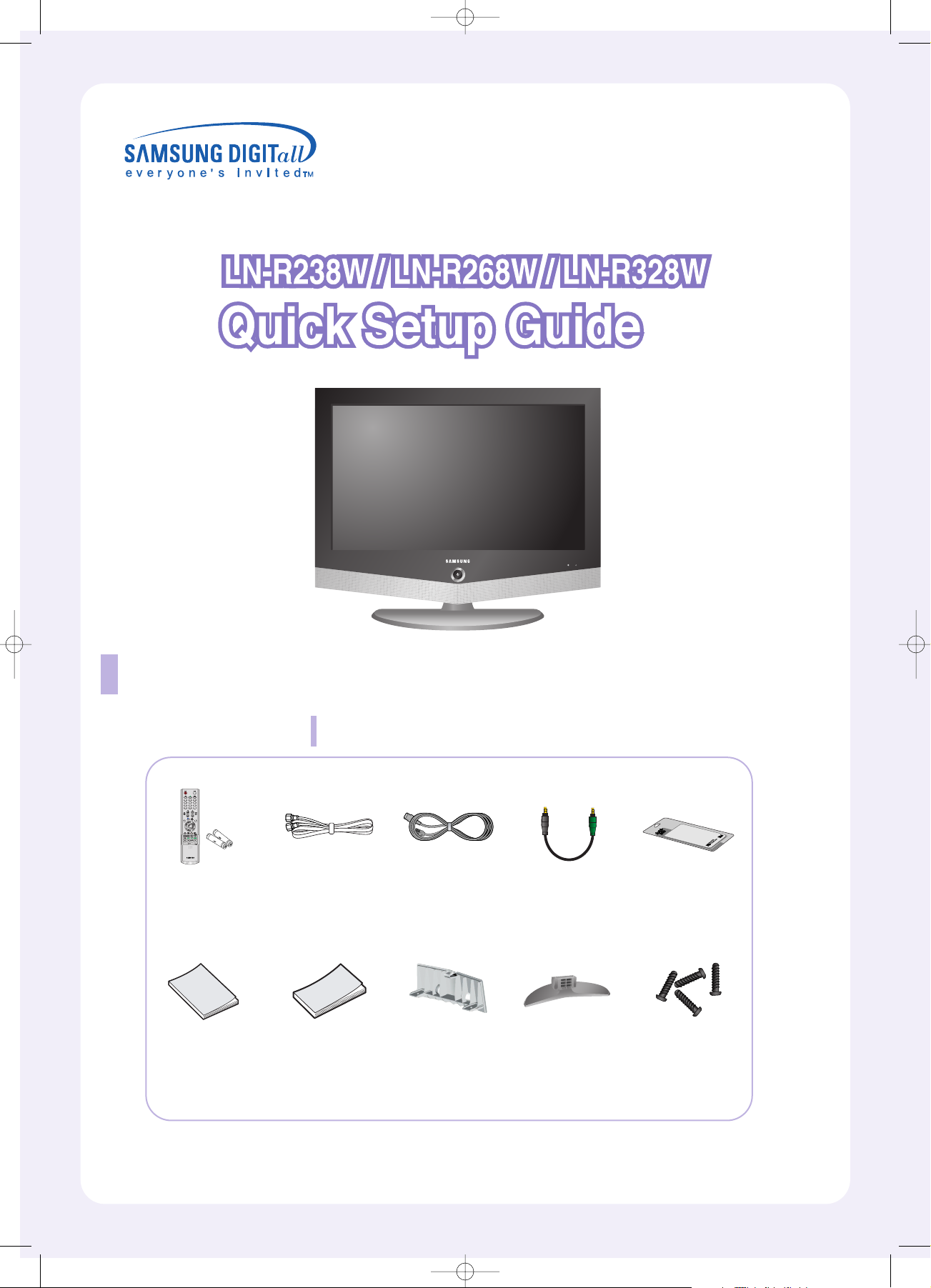
Please make sure the following items are included with your LCD TV.
If any items are missing, contact your dealer.
Accessories
List of Parts
BN68-00515V-00
Remote Control
(BN59-00455A)
& Batteries (AAA x 2)
Anynet Cable
(BN39-00518B)
Owner’s
Instructions
Power Cord
(3903-000085)
Anynet AV
Owner’s
Instructions
Cover-Bottom
(BN68-01674A)
RF Cable
(AA39-00039A)
Stand
(23”, 26” BN96-01727A)
(32” BN96-01733A)
Cleaning Cloth
Stand Screw
(6002-001294) x 4
M4 X L16
BN68-00515V-00.qxd 1/11/05 4:10 PM Page 1
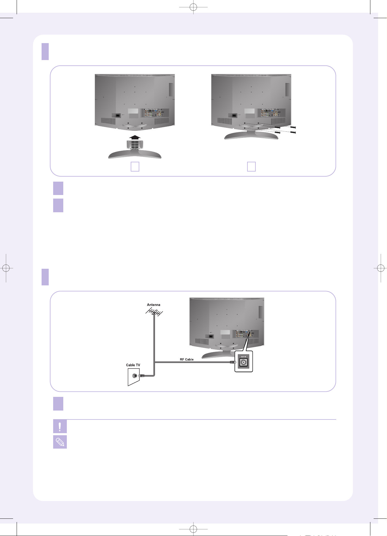
Connecting Antenna/Cable TV
1
Plug the antenna/cable TV lead into the ANT IN terminal on the back of the TV.
When connecting the RF cable to the antenna input terminal, keep the copper wire portion of
the RF cable straight to avoid bending it.
For more detailed antenna/cable TV connections, refer to the owner's Instructions.
Installing the stand
1
Lower the TV set in the direction of the arrow and fix the stand.
2
Use the four screws to tightly fix the stand.
21
BN68-00515V-00.qxd 1/11/05 4:10 PM Page 2
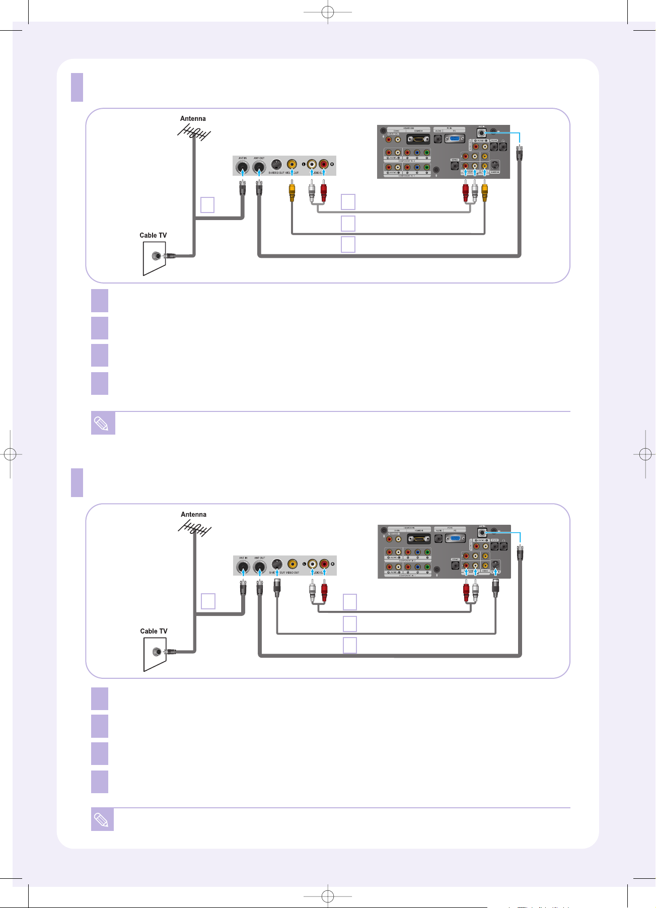
Connecting an S-VHS VCR
Connect the cable TV or antenna to the ANT IN terminal on the back of the VCR.
Connect an RF cable between the ANT OUT terminal on the VCR and the ANT IN terminal on the TV.
Connect an audio cable between the AUDIO OUT jacks on the VCR and the AV IN [R-AUDIO-L]
jacks on the TV.
Connect an S-Video cable between the S-VIDEO OUT jack on the VCR and the S-VIDEO IN jack on the TV.
An S-Video cable is usually included with an S-VHS VCR.
S-Video Cable (Option)
Audio Cable (Option)
TV Rear Panel
RF Cable
VCR Rear Panel
1
2
4
3
1
2
3
4
1
2
4
3
Connecting a VCR
Connect the cable TV or antenna to the ANT IN terminal on the back of the VCR.
Connect an RF cable between the ANT OUT terminal on the VCR and the ANT IN terminal on the TV.
Connect an audio cable between the AUDIO OUT jacks on the VCR and the AV IN [R-AUDIO-L]
jacks on the TV.
Connect a video cable between the VIDEO OUT jack on the VCR and the AV IN [VIDEO] jack on the TV.
If you have a “mono” (non-stereo) VCR, use a Y-connector (not supplied) to hook up to the
R-AUDIO-L jacks on the TV
1
2
3
4
TV Rear Panel
RF Cable
Audio Cable (Option)
Video Cable (Option)
VCR Rear Panel
BN68-00515V-00.qxd 1/11/05 4:10 PM Page 3

Connecting a Digital TV Set-top box
Connecting an Amplifier/DVD Home Theater
1
Connect an audio cable between the AUDIO OUT [R-AUDIO-L] jacks on the TV and the
AUDIO IN jacks on the Amplifier/DVD Home Theater.
1
Connecting a DVD Player
Connect a component cable between the COMPONENT IN 1 or COMPONENT IN 2 [PR, PB, Y] jacks
on the TV and the COMPONENT [Y, P
B
, PR] jacks on the DVD player.
Connect an audio cable between the COMPONENT IN 1 or COMPONENT IN 2 [R-AUDIO-L] jacks
on the TV and the AUDIO OUT jacks on the DVD player.
For an explanation of Component video, see your DVD player owner's manual.
Component Cable (Option)
Audio Cable (Option)
TV Rear Panel
DVD Player Rear Panel
Component Cable (Option)
Audio Cable (Option)
TV Rear Panel
Set-Top Box Rear Panel
1
2
Connect a component cable between the COMPONENT IN 1 or COMPONENT IN 2 [PR, PB, Y]
jacks on the TV and the COMPONENT [Y, P
B
, PR] jacks on the Set-top box.
Connect an audio cable between the COMPONENT IN 1 or COMPONENT IN 2 [R-AUDIO-L] jacks
on the TV and the AUDIO OUT jacks on the Set-top box.
1
2
2
1
2
1
Audio Cable (Option)
TV Rear Panel
Amplifier/
DVD Home Theater
BN68-00515V-00.qxd 1/11/05 4:10 PM Page 4

Connecting a DVD /Set-top box via DVI
Connecting a DVD /Set-top box via HDMI
DVI-to-HDMI Cable (Option)
Audio Cable (Option)
TV Rear Panel
DVD Player Rear Panel
1
2
Connect a DVI-to-HDMI cable or DVI-HDMI Adapter between the HDMI/DVI connector on the TV
and the DVI connector on the DVD player/Set-top box.
Connect an audio cable between the DVI IN [R-AUDIO-L] jacks on the TV and the AUDIO OUT jacks
on the DVD player/Set-top box.
1
2
HDMI Cable (Option)
TV Rear PanelDVD Player Rear Panel
1
Connect an HDMI cable between the HDMI/DVI connector on the TV and the HDMI connector
on the DVD player/Set-top box.
1
Connecting a PC
2
1
Connect a PC video cable (D-Sub) between PC IN [PC] connector on the TV and the PC output
connector on your computer.
Connect a PC audio cable between PC IN [AUDIO] on the TV and the Audio Out of the sound card
on your computer.
1
2
PC Audio Cable (Option)
PC Video Cable (Option)
TV Rear Panel
PC
BN68-00515V-00.qxd 1/11/05 4:10 PM Page 5

Plug & Play
When the TV is initially powered on, several basic customer settings proceed automatically and subsequently.
1
Press the
POWER
button
on the remote control.
The message
“Start Plug & Play” is
displayed with “OK” selected.
2
Select the appropriate
language by pressing the
UP/DOWN
buttons.
Press the
ENTER
button
to confirm your choice.
4
Press the
UP/DOWN
buttons to select “Air”, “STD”,
“HRC”, or “IRC”, then press
the
ENTER
button.
5
Press the
ENTER
button
to select “Start”.
The TV will begin memorizing
all of the available channels.
6
Press the
ENTER
button.
Press the
LEFT/RIGHT
buttons to move to the
“Hour”, “Minute” or “am/pm”.
Set the “Hour”, “Minute” or
“am/pm” by pressing the
UP/DOWN
buttons.
Press the
ENTER
button.
7
The message
“Enjoy your watching.”
is displayed.
3
The message
“Check Antenna Input” is
displayed with “OK” selected.
Press the
ENTER
button.
To Select the Source
You can select the TV mode or an input source connected to the TV set.
Use this button to choose an input source that you would like to watch.
You can only select a source if it is connected to your TV.
Press the SOURCE button on the remote control
BN68-00515V-00.qxd 1/11/05 4:10 PM Page 6

Remote control Functions Chart
POWER
Turns the TV on and off.
STILL
Press to stop the action during a
particular scene. Press again to
resume normal video.
NUMBER BUTTONS
Press to change the channel.
+100
Press to select channels over 100.
For example, to select channel 121,
press “+100”, then press “2” and “1”.
MUTE
Press to temporarily cut off the sound.
Anynet
Press the Anynet button to bring up
the Anynet menu. (Refer to “Anynet
AV Owner’s Instructions”.)
MENU
Displays the main on-screen menu.
S.MODE
Adjusts the TV sound by selecting
one of the preset factory settings
(or selects your personal,
customized sound settings).
MTS
(Multi channel Television Stereo)
Press to choose stereo, mono or
Separate Audio Program
(SAP broadcast).
AUTO PROG.
Press to automatically store
selected TV/Cable channels.
ADD/DEL
Use to store and delete channels
to/from memory.
DNIe
DNIe Demo On/Off.
Off : DNIe Demo mode is deactivated.
On : The right-hand side of the screen
shows the improved DNIe image.
The left-hand side of the screen
shows the original image.
VCR/DVD Functions
(Only Anynet mode)
- Rewind
- Stop
- Play/Pause
- Fast Forward
CAPTION
Controls the caption decoder.
PIP
Picture-in-Picture ON/OFF.
SLEEP
Press to select a time for the TV to
turn off automatically.
PRE-CH
Tunes to the previous channel.
CH and CH
(Channel UP/Down)
Press CH or CH to change
channels.
VOL + and VOL -
Press to increase or decrease the
volume.
SOURCE
Press to display all of the available
video sources.
INFO
Use to see information on the
current broadcast.
EXIT
Press to exit the menu.
UP / DOWN / LEFT /
RIGHT / ENTER
Use to select on-screen menu items
and change menu values.
SRS
Selects TruSurround XT mode.
P.MODE
Adjusts the TV picture by selecting
one of the preset factory settings.
P.SIZE
Press to change the screen size.
PC
Press to switch to the PC mode.
SWAP
Press to interchange the main picture
and the sub (PIP) picture.
SIZE
Press to make the PIP window small,
double1, double2.
POSITION
Press to select the position of sub (PIP)
picture.
RESET
When your remote does not work,
change the batteries and press
the RESET button for 2-3 seconds
before use.
BN68-00515V-00.qxd 1/11/05 4:10 PM Page 7

FAQ
If a still image is displayed for an
extended period of time, residual
images or blurring may appear.
When you need to leave the TV
unused for an extended period of
time, adjust the settings so that the
TV automatically goes into energy
saving mode or activates the screen
saver to display moving images.
No picture or sound.
Try another channel.
Press the SOURCE button.
Make sure the TV is plugged in.
Check the antenna connections.
Poor picture
Try another channel.
Adjust the antenna.
Check all wire connections.
Image is not centered on the
screen.
Adjust the horizontal and vertical
position. The screen position must
be adjusted on the output source
(i.e. STB) with a digital signal.
“Not Supported Mode” message.
Check the maximum resolution and
the frequency of the Video Adapter.
Compare these values with the data
in the Display Modes.
Remote control malfunctions
Replace the remote control batteries.
Clean the upper edge of the remote
control (transmission window).
Check the battery terminals.
No sound or sound is too low at
maximum volume.
First, check the volume of units
connected to your TV (digital
broadcasting receiver, DTV, DVD,
cable broadcasting receiver, VCR,
etc.). Then, adjust the TV volume
accordingly.
Image is not stable and may
appear to vibrate.
If the setting is not correct, use your
computer utility program to change
the display settings.
Check the following
items before calling
a Samsung authorized
service center.
BN68-00515V-00.qxd 1/11/05 4:10 PM Page 8
 Loading...