


Smart Signage User Manual (By Model)
This manual provides information about your Smart Signage including supported types and product specications per model.
QBR (QB43R QB49R QB50R QB55R QB65R QB75R QB85R QB98R)
QBR-N (QB55R-N QB65R-N QB75R-N QB85R-N)
QER (QE82R)
QMR (QM32R QM43R QM49R QM50R QM55R QM65R QM75R QM85R)
QMR-T (QM32R-T QM43R-T QM55R-T)
The color and the appearance may differ depending on the product, and the content in the
manual is subject to change without prior notice to improve the performance.
Recommended hours of use per day for the QBR*(except for QB98R), QM32R, and QER models is
less than 16 hours.
If the product is used for longer than 16 hours a day, the warranty may be void.
© Samsung Electronics
Samsung Electronics owns the copyright for this manual. Use or reproduction of this manual in parts or entirety without the authorization of Samsung Electronics is prohibited. Trademarks other than Samsung Electronics are
property of their respective owners.
Table of contents
Preparations
Checking the Components 3
Parts 4
QM32R/Q*43R/Q*49R/Q*50R/Q*55R*/
Q*65R*/Q*75R*/Q*85R*/QE82R/QM32R-T/
QM43R-T/QM55R-T
QB98R
5
Anti-theft Lock 6
Ports 7
Q*43R/Q*49R/Q*50R/Q*55R*/Q*65R*/
Q*75R*/Q*85R*/QE82R
QM32R
8
QB98R
9
QM32R-T
QM43R-T/QM55R-T
Control menu 12
Administrator menu (Supported models:
QMR-T
Precautions when handling the panel 14
Before Installing the Product (Installation
Guide) 15
Tilting Angle and Rotation 15
Ventilation 15
10
) 13
4
7
11
Using a touchscreen monitor
(Supported models: QMR-T)
Touchscreen monitor 18
Read below before using the product 18
Connecting the touch overlay 18
Connecting the touchscreen monitor 19
Connecting to a PC 19
Connecting to a laptop or tablet PC 19
Configuring the touchscreen monitor
settings 20
Calibration 20
Specifications
General 22
Preset Timing Modes 24
Appendix
License 25
Installing the Wall Mount 16
Preparing before installing Wall-Mount 16
Installing the Wall Mount 16
Wall Mount Kit Specifications (VESA) 17
2
Chapter 01
Preparations
Contact the vendor where you
"
purchased the product if any
components are missing.
The appearance of the components
"
may differ from the images shown.
A stand is not provided with the
"
product. To install a stand, you can
purchase one separately.
The RS232C adapter can be used to
"
connect to another monitor using the
D-SUB (9-pin) type RS232C cable.
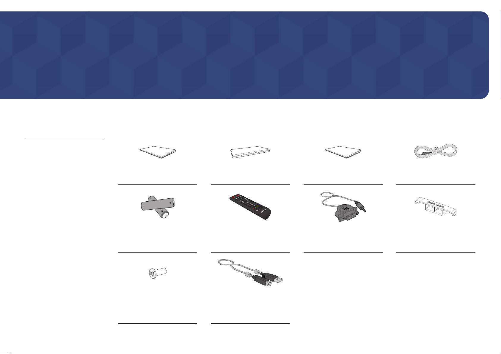
Checking the Components
Quick Setup Guide
Batteries (AAA x 2)
(Not available in some locations)
(Not available in some locations)
Warranty card
Remote Control RS232C adapter
Regulatory guide Power cord
HOLDER-CABLE
(Supported models: Q*65R*,
Q*75R*, Q*85R*, QB98R, QE82R)
Holder-Ring x 4
(Supported models: Q*43R,
Q*49R, Q*50R, Q*55R*, Q*65R*,
Q*75R*, QM43R-T, QM55R-T)
TOUCH OUT cable x 2
(Supported models: QMR-T)
3
Parts
"
The color and shape of parts may differ from what is shown. Specifications are subject to change without notice
to improve quality.
Parts Description
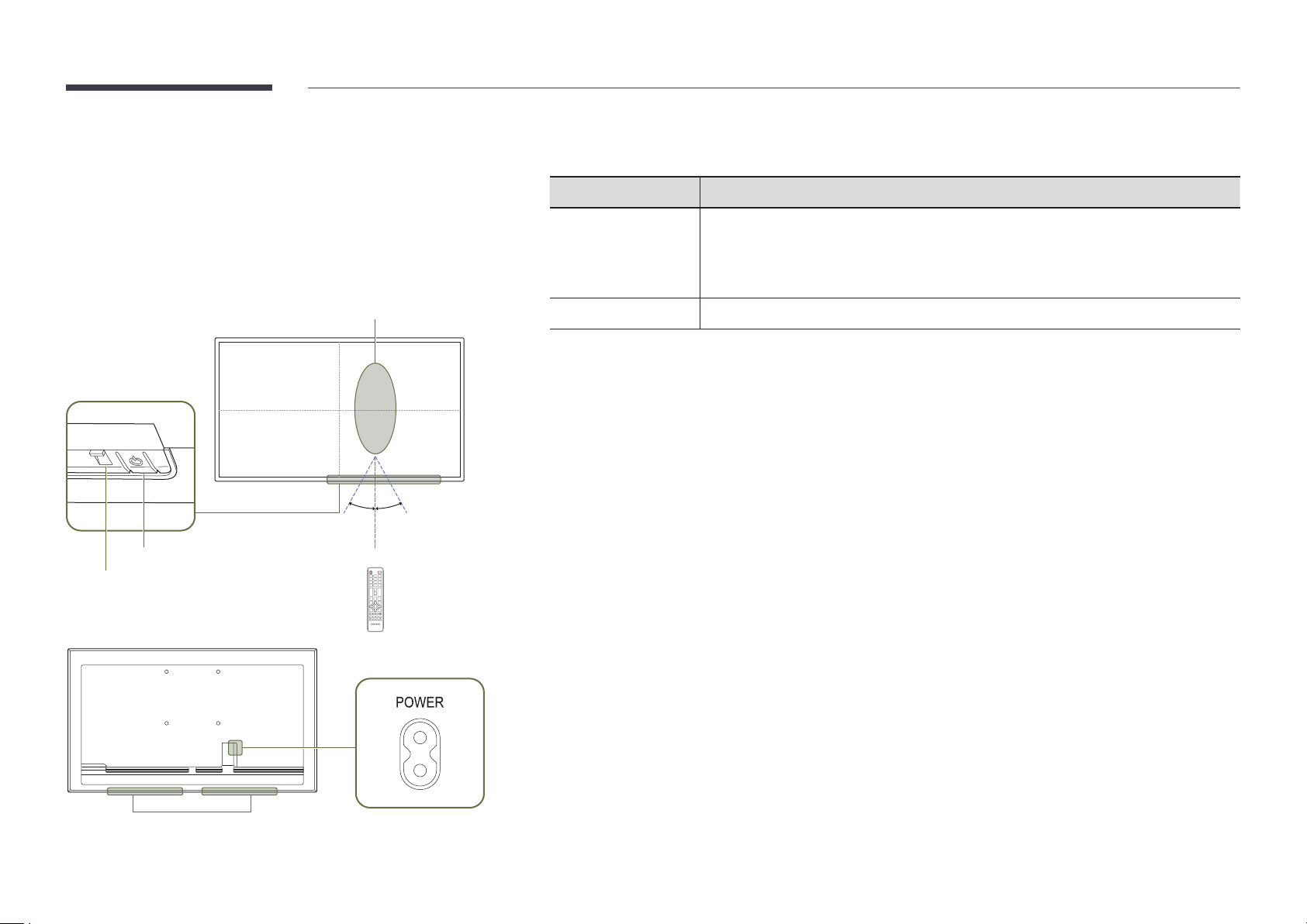
QM32R/Q*43R/Q*49R/Q*50R/Q*55R*/ Q*65R*/Q*75R*/Q*85R*/QE82R/ QM32R-T/QM43R-T/QM55R-T
Remote sensor
30°
4 m
30°
2.5 m
2.5 m
Power button
Power indicator
Press a button on the remote control pointing at the sensor on the front of the product
Remote sensor
Power button
Use the remote control within 2.5 m to 4 m from the sensor on the product at an angle of 30° from the left and
right.
"
To enhance the IR receiver performance, connect an external IR cable (sold separately) to the IR IN port.
to perform the corresponding function.
"
Using other display devices in the same space as the remote control of this product
can cause the other display devices to be inadvertently controlled.
Turns the product on or off.
Speaker
4
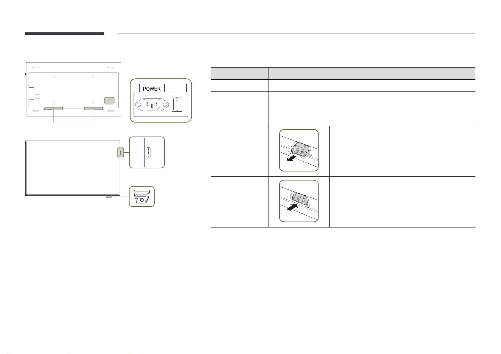
QB98R
"
The color and shape of parts may differ from what is shown. Specifications are subject to change without notice
to improve quality.
Parts Description
Speaker
ON/OFF
Spacer logo
Remote sensor & Power button
Spacer logo
Remote sensor
Power button
Use the remote control within 7 m to 10 m from the sensor on the product at an angle of 30° from the left and right.
"
To enhance the IR receiver performance, connect an external IR cable (sold separately) to the IR IN port.
Do not pull on the spacer logo using force. The logo may tear or break off.
Press a button on the remote control pointing at the bottom of the product face to
perform the function. The remote control sensor is located on the bottom of the product.
"
Using other display devices in the same space as the remote control of this product
can cause the other display devices to be inadvertently controlled.
To use remote/eco sensor, make sure the sliding power button
is protruding from the bottom of the product.
To use the power button, make sure the sliding power button
is not protruding from the bottom of the product.
5
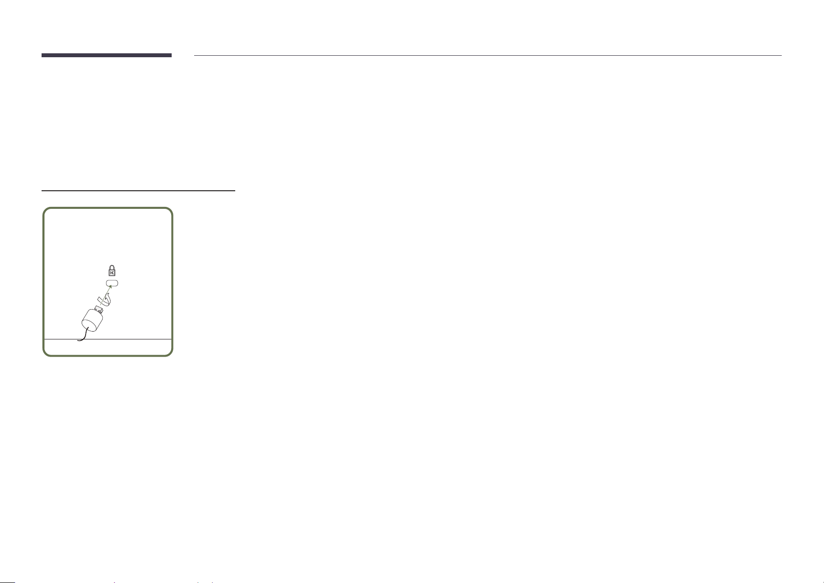
Anti-theft Lock
"
An anti-theft lock allows you to use the product securely even in public places.
"
The locking device shape and locking method depend on the manufacturer. Refer to the user guide provided with your anti-theft locking device for details.
"
The following images are for reference only. Real-life situations may differ from what is shown in the images.
"
Supported model: QB98R
To lock an anti-theft locking device:
Fix the cable of your anti-theft locking device to a heavy object such as a desk.
1
Put one end of the cable through the loop on the other end.
2
Insert the locking device into the anti-theft lock slot at the back of the product.
3
Lock the locking device.
4
– An anti-theft locking device can be purchased separately.
– Refer to the user guide provided with your anti-theft locking device for details.
– Anti-theft locking devices can be purchased at electronics retailers or online.
6
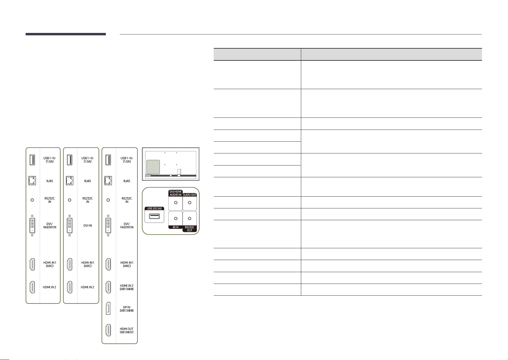
Ports
QM43R / QM49R / QM50R /
QE82R
QB43R / QB49R / QB50R /
Q*43R/Q*49R/Q*50R/Q*55R*/Q*65R*/ Q*75R*/Q*85R*/QE82R
QB55R / QB55R-N / QB65R /
QB65R-N / QB75R / QB75R-N /
QB85R / QB85R-N
"
The color and shape of parts may differ from what is shown.
Specifications are subject to change without notice to improve quality.
QM55R / QM65R / QM75R /
QM85R
Port Description
USB 1 ¨(1.0A)
RJ45
RS232C IN
DVI/MAGICINFO IN
DVI IN
Connect to a USB memory device.
"
The USB ports on the product accept a maximum constant current of 1.0A.
If the maximum value is exceeded, USB ports may not work.
Connects to MDC and the Internet using a LAN cable. (10/100 Mbps)
"
Use Cat7(*STP Type) cable for the connection.
*Shielded Twist Pair.
Connects to MDC using an RS232C adapter.
DVI IN: Connects to a source device using a DVI cable or HDMI-DVI cable.
MAGICINFO IN: Connects to a network box using DP-DVI cable to use Magicinfo.
HDMI IN 1 (ARC)
HDMI IN 2
HDMI IN 2 (DAISY CHAIN IN)
DP IN (DAISY CHAIN IN)
HDMI OUT (DAISY CHAIN OUT)
USB 2(0.5A)
DVI/HDMI AUDIO IN
AUDIO OUT
IR IN
RS232C OUT
Connects to a source device using a HDMI cable or HDMI-DVI cable.
• Connects to a source device using a HDMI cable or HDMI-DVI cable.
• Connects to another product using a HDMI cable.
Connects to a PC using a DP cable.
Connects to another product using a HDMI cable.
Connect to a USB memory device.
"
The USB ports on the product accept a maximum constant current of
0.5A. If the maximum value is exceeded, USB ports may not work.
Receives sound from a source device via an audio cable.
Outputs sound to an audio device via an audio cable.
Connects to an external IR cable that receives signals from the remote control.
Connects to MDC using an RS232C adapter.
7
QM32R
Port Description
"
The color and shape of parts may differ from what is shown.
Specifications are subject to change without notice to improve quality.
USB 1 ¨(1.0A)
HDMI IN 1 (ARC)
RJ45
RS232C IN
HDMI IN 2 (DAISY CHAIN IN)
DP IN (DAISY CHAIN IN)
HDMI OUT (DAISY CHAIN OUT)
USB 2(0.5A)
AUDIO OUT
IR IN
Connect to a USB memory device.
"
The USB ports on the product accept a maximum constant current of 1.0A.
If the maximum value is exceeded, USB ports may not work.
Connects to a source device using a HDMI cable or HDMI-DVI cable.
Connects to MDC and the Internet using a LAN cable. (10/100 Mbps)
"
Use Cat7(*STP Type) cable for the connection.
*Shielded Twist Pair.
Connects to MDC using an RS232C adapter.
• Connects to a source device using a HDMI cable or HDMI-DVI cable.
• Connects to another product using a HDMI cable.
Connects to a PC using a DP cable.
Connects to another product using a HDMI cable.
Connect to a USB memory device.
"
The USB ports on the product accept a maximum constant current of
0.5A. If the maximum value is exceeded, USB ports may not work.
Outputs sound to an audio device via an audio cable.
Connects to an external IR cable that receives signals from the remote control.
RS232C OUT
Connects to MDC using an RS232C adapter.
8

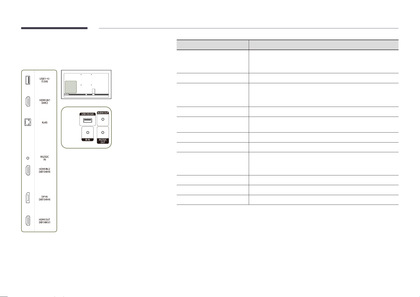
QB98R
Port Description
"
The color and shape of parts may differ from what is shown.
Specifications are subject to change without notice to improve quality.
RJ45
USB 1 ¨(1.0A)
DVI/MAGICINFO IN
RS232C IN
RS232C OUT
DVI/HDMI AUDIO IN
HDMI IN 1 (ARC)
HDMI IN 2 (DAISY CHAIN IN)
DP IN (DAISY CHAIN IN)
HDMI OUT (DAISY CHAIN OUT)
USB 2(0.5A)
Connects to MDC and the Internet using a LAN cable. (10/100 Mbps)
"
Use Cat7(*STP Type) cable for the connection.
*Shielded Twist Pair.
Connect to a USB memory device.
"
The USB ports on the product accept a maximum constant current of 1.0A.
If the maximum value is exceeded, USB ports may not work.
DVI IN: Connects to a source device using a DVI cable or HDMI-DVI cable.
MAGICINFO IN: Connects to a network box using DP-DVI cable to use Magicinfo.
Connects to MDC using an RS232C adapter.
Connects to MDC using an RS232C adapter.
Receives sound from a source device via an audio cable.
Connects to a source device using a HDMI cable or HDMI-DVI cable.
• Connects to a source device using a HDMI cable or HDMI-DVI cable.
• Connects to another product using a HDMI cable.
Connects to a PC using a DP cable.
Connects to another product using a HDMI cable.
Connect to a USB memory device.
"
The USB ports on the product accept a maximum constant current of
0.5A. If the maximum value is exceeded, USB ports may not work.
AUDIO OUT
IR IN
Outputs sound to an audio device via an audio cable.
Connects to an external IR cable that receives signals from the remote control.
9

QM32R-T
Port Description
"
The color and shape of parts may differ from what is shown.
Specifications are subject to change without notice to improve quality.
USB 1 ¨(1.0A)
HDMI IN 1 (ARC)
RJ45
RS232C IN
HDMI IN 2 (DAISY CHAIN IN)
DP IN (DAISY CHAIN IN)
HDMI OUT (DAISY CHAIN OUT)
USB 2(0.5A)
AUDIO OUT
IR IN
Connect to a USB memory device or TOUCH OUT cable.
"
The USB ports on the product accept a maximum constant current of 1.0A.
If the maximum value is exceeded, USB ports may not work.
Connects to a source device using a HDMI cable or HDMI-DVI cable.
Connects to MDC and the Internet using a LAN cable. (10/100 Mbps)
"
Use Cat7(*STP Type) cable for the connection.
*Shielded Twist Pair.
Connects to MDC using an RS232C adapter.
• Connects to a source device using a HDMI cable or HDMI-DVI cable.
• Connects to another product using a HDMI cable.
Connects to a PC using a DP cable.
Connects to another product using a HDMI cable.
Connect to a USB memory device or TOUCH OUT cable.
"
The USB ports on the product accept a maximum constant current of
0.5A. If the maximum value is exceeded, USB ports may not work.
Outputs sound to an audio device via an audio cable.
Connects to an external IR cable that receives signals from the remote control.
RS232C OUT
TOUCH OUT SCREEN
TOUCH OUT PC
Connects to MDC using an RS232C adapter.
Connect to a USB port on the product to use the touch function.
Connect to a USB port on a PC to use the touch function.
10

QM43R-T/QM55R-T
Port Description
"
The color and shape of parts may differ from what is shown.
Specifications are subject to change without notice to improve quality.
USB 1 ¨(1.0A)
RJ45
RS232C IN
DVI/MAGICINFO IN
HDMI IN 1 (ARC)
HDMI IN 2 (DAISY CHAIN IN)
DP IN (DAISY CHAIN IN)
HDMI OUT (DAISY CHAIN OUT)
USB 2(0.5A)
DVI/HDMI AUDIO IN
Connect to a USB memory device or TOUCH OUT cable.
"
The USB ports on the product accept a maximum constant current of 1.0A.
If the maximum value is exceeded, USB ports may not work.
Connects to MDC and the Internet using a LAN cable. (10/100 Mbps)
"
Use Cat7(*STP Type) cable for the connection.
*Shielded Twist Pair.
Connects to MDC using an RS232C adapter.
DVI IN: Connects to a source device using a DVI cable or HDMI-DVI cable.
MAGICINFO IN: Connects to a network box using DP-DVI cable to use Magicinfo.
Connects to a source device using a HDMI cable or HDMI-DVI cable.
• Connects to a source device using a HDMI cable or HDMI-DVI cable.
• Connects to another product using a HDMI cable.
Connects to a PC using a DP cable.
Connects to another product using a HDMI cable.
Connect to a USB memory device or TOUCH OUT cable.
"
The USB ports on the product accept a maximum constant current of
0.5A. If the maximum value is exceeded, USB ports may not work.
Receives sound from a source device via an audio cable.
AUDIO OUT
IR IN
RS232C OUT
TOUCH OUT SCREEN
TOUCH OUT PC
Outputs sound to an audio device via an audio cable.
Connects to an external IR cable that receives signals from the remote control.
Connects to MDC using an RS232C adapter.
Connect to a USB port on the product to use the touch function.
Connect to a USB port on a PC to use the touch function.
11

Control menu
"
The power button(«) is located on the bottom of the product.
"
If you press the power button on the product when the product is
turned on, the control menu will be displayed.
Power Off
Press: Move Press & Hold: Select
Source
Items Description
Power off the product.
Power Off
Source
"
The power button can only be used for Power Off and Source.
"
To exit from the control menu screen, wait for 3 seconds or more without pressing the power button.
• With the control menu screen displayed, briefly press the power button to
move the cursor to
turn off the product.
Select the connected input source.
• With the control menu screen displayed, briefly press the power button to
move the cursor to
display the input source screen.
• With the input source screen displayed, press and hold the power button to
switch to the desired input source.
Power Off, and then press and hold the power button to
Source, and then press and hold the power button to
12

Administrator menu (Supported models: QMR-T)
Buttons Description
Volume
Adjust the Volume.
• Select Volume from the administrator menu.
"
Touching and holding on the screen when the product is turned on
displays the administrator menu.
"
If the touchscreen control is not available, use the remote control to
go to System → Touch Control → Touch Control and select On from the
OSD menu.
"
If the administrator menu is not displayed, use the remote control to
go to System → Touch Control → Admin Menu Lock and select Off from
the OSD menu.
"
This menu is not displayed, when using touch mode on a connected PC.
Home
Menu
Source
Power
Enter Home screen.
• Select Home from the administrator menu.
Display the OSD menu.
To change settings, select a menu item.
• Select Menu from the administrator menu.
Select the connected input source.
Select an input source from the displayed list of input sources.
• Select Source from the administrator menu.
Power off the product.
• Select Power from the administrator menu.
Volume Home Menu Source Power
13

Precautions when handling the panel
"
The color and the appearance may differ depending on the model.
Do not stand the product as shown in the image. The panel is fragile
and can get damaged.
Lay the product down to handle it as shown in the image. (the
packaging can be used).
"
Supported models: 85 inches or more
Ensure you use the handles on the back when moving the product.
"
Supported models: 85 inches or more
15 mm
Do not hold or grasp any area of the product within 15 mm from the
front.
14

Before Installing the Product (Installation Guide)
Ventilation
"
Contact Samsung Customer Service Center for further details.
Installation on a Perpendicular Wall
To prevent injury, this apparatus must be securely attached to the floor/wall in accordance
with the installation instructions.
• Ensure that an authorized installation company installs the wall mount.
• Otherwise, it may fall and cause personal injury.
• Make sure to install the specified wall mount.
Tilting Angle and Rotation
"
Contact Samsung Customer Service Center for further details.
• The product can be tilted at a maximum angle of 15° from a perpendicular wall surface.
• To use the product in Portrait mode, rotate clockwise until the power indicator (A or B) is
positioned as shown in the images below.
15°
A
A
"
Do not use this model installed on a ceiling, floor, or table.
B
B
A Minimum 40 mm
B Ambient temperature: Under 35 °C
"
When installing the product on a perpendicular wall, allow at least
40 mm of space between the product and wall surface for ventilation
and ensure that the ambient temperature is kept below 35 °C.
Installation on an Indented Wall
A Minimum 40 mm
B Minimum 70 mm
C Minimum 50 mm
D Minimum 50 mm
E Ambient temperature: Under 35 °C
"
When installing the product on an indented
wall, allow at least the space specified above
between the product and wall for ventilation
and ensure that the ambient temperature is
kept below 35 °C.
D
A
B
B
D
C
B
A
C
E
15

Installing the Wall Mount
Preparing before installing Wall-Mount
To install a wall-mount from another manufacturer, use the Holder-Ring.
"
For the QM32R-T, QB85R, QB85R-N, QM85R and 82-inch models that it does not provide Holder-Ring(A).
A
Installing the Wall Mount
• The wall mount kit (sold separately) allows you to mount the product on the wall.
• The provided image is only for reference. For detailed information on installing the wall mount, see instructions
provided with the wall mount.
• We recommend you contact a technician for assistance when installing the wall mount bracket.
• Samsung Electronics is not responsible for any damage to the product or injury to yourself or others if you select
to install the wall mount on your own.
16

Wall Mount Kit Specications (VESA)
"
Install your wall mount on a solid wall perpendicular to the floor. To
install the product on the other wall area, contact the nearest agency.
If you install the product on a slanted wall, it may fall and result in
severe personal injury.
• Samsung wall mount kits contain a detailed installation manual and all parts necessary for assembly are
provided.
• Do not use screws that are longer than the standard length or do not comply with the VESA standard screw
specifications. Screws that are too long may cause damage to the inside of the product.
• For wall mounts that do not comply with the VESA standard screw specifications, the length of the screws may
differ depending on the wall mount specifications.
• Do not fasten the screws too firmly. This may damage the product or cause the product to fall, leading to
personal injury. Samsung is not liable for these kinds of accidents.
• Samsung is not liable for product damage or personal injury when a non-VESA or non-specified wall mount is
used or the consumer fails to follow the product installation instructions.
• Do not mount the product at more than a 15 degree tilt.
• Always have at least two people mount the product on a wall. (Four or more people for the 82-inch size and
larger models.)
• Standard dimensions for wall mount kits are shown in the table below.
Model Name
QB43R / QB49R / QB50R /
QB55R / QB55R-N / QM32R /
QM43R / QM49R / QM50R /
QM55R / QM32R-T / QM43R-T /
QM55R-T
QB65R / QB65R-N / QB75R /
QB75R-N / QM65R / QM75R
QB85R / QB85R-N / QM85R /
QE82R
QB98R 900 × 600
"
Do not install your Wall Mount Kit while your product is turned on. It may result in personal injury due to electric
shock.
VESA screw hole specs (A * B) in
millimeters
200 × 200
400 × 400
600 × 400
Standard Screw Quantity
M8 4
17

Chapter 02
(1.0A), USB 2(0.5A)
Using a touchscreen monitor (Supported models: QMR-T)
Touchscreen monitor
Control a PC by tapping the screen instead of using an input device such as a keyboard or
mouse. The touch screen functions by detecting a minute electric current that runs through
your body (capacitive). Make sure to use the surface of your finger tip when tapping the screen.
Read below before using the product
• Take extra care to ensure an electrical substance does not contact the screen. The screen
may not function properly if there is static.
• Do not press hard on the touchscreen with your finger tip. Do not use a sharp object when
tapping the screen. The screen may break or get damaged.
• Do not tap the screen while wearing a glove, with a dirty finger, or using something sharp
such as your fingernail or a ballpoint pen. The screen may not function properly.
• Take extra care to ensure the screen does not contact moisture. The touch sensor may not
function properly.
• Displaying a still image on the screen for an extended period of time may cause after
images (screen degradation) or stains. Switch off the screen when not in use.
Connecting the touch overlay
"
Touch functions are not supported in applications other than the OSD menu and
administrator menu.
Connect the TOUCH OUT cable between TOUCH OUT SCREEN and USB 1 ¨(1.0A) or USB
2(0.5A) port on the product.
USB 1
TOUCH OUT SCREEN
18

Connecting the touchscreen monitor
"
Connecting parts may differ in different products.
Connecting to a PC
Connect your PC to the product using a HDMI or HDMI-DVI cable.
1
Connecting the devices using a HDMI cable
HDMI IN
Connecting the devices using a HDMI-DVI cable
Connect the power cable from the product to the power outlet.
2
After the power supply is connected, the product automatically detects and switches to the
3
connected input source.
"
If the screen appears blank, turn the product off and then on again.
Connect the TOUCH OUT PC port on the product to a USB port on the PC using the TOUCH
4
OUT cable.
TOUCH OUT PC
Connecting to a laptop or tablet PC
A laptop or tablet PC can be connected to the product using the same method when connecting
a desktop PC.
"
If touchscreen control is not available after the devices are connected
– Make sure to connect the HDMI or HDMI-DVI cable before connecting the TOUCH OUT
cable.
– If touchscreen control is still unavailable after the cables are connected properly,
disconnect the TOUCH OUT cable and then connect it again.
HDMI IN
19

Conguring the touchscreen monitor settings
To properly use the touch function of the product in Windows, go to Tablet PC Settings and calibrate the product.
"
First connect the touchscreen monitor before configuring the following settings.
"
The maximum number of touchscreen monitors that can be connected simultaneously varies, depending on the operating system and graphics card settings.
"
If Tablet PC Settings is not found in Control Panel, search for Tablet PC Settings from Search Control Panel.
"
If used in a multi-screen setup, make sure you have configured QMR-T as the main display.
Tap the page displayed on the product with your finger.
Calibration
"
Instructions below are for Windows 8. The same method applies to both Windows 7,
Windows 8 and Windows 10.
"
After changing the Picture Size from the OSD menu, you may need to calibrate the picture
settings again.
"
Upon occurrence of an error during calibration, go to Tablet PC Settings. In the Display tab,
tap Reset and calibrate again.
In the Display tab, select Setup under Configure.
1
2
"
In dual monitor mode: If the following page does not appear on the product, press the
Enter key to display the page.
Touch this screen to identity it as the touchscreen.
If this is not the Tablet PC screen, press Enter to move to the next screen. To close the tool, press Esc.
20

Select the product from Display under Display options. Next, select Calibrate.
3
Perform calibration following the onscreen instructions displayed as shown in the image.
4
After calibration is complete, the message Do you want to save the calibration data?
5
appears. Select Yes.
Digitizer Calibration Tool
Do you want to save the calibration data?
Yes No
The touchscreen monitor has been calibrated successfully.
6
"
Selecting Reset will remove the calibration data.
To provide calibration samples, tap the crosshair each
time that it appears on the screen.
Right-click anywhere on the screen to return to the
last calibration point. Press the Esc button to close
the tool. Do not change your screen orientation until
you have completed the calibration process.
21

Chapter 03
Specications
General
Model Name QM32R / QM32R-T QB43R / QM43R / QM43R-T QB49R / QM49R QB50R / QM50R
Panel
Size
Display area
Model Name QB55R / QB55R-N / QM55R / QM55R-T QB65R / QB65R-N / QM65R QB75R / QB75R-N / QM75R
Size
Panel
Display area
Model Name QB85R / QB85R-N / QM85R QB98R QE82R
Size
Panel
Display area
32 CLASS (31.5 inches / 8 0.1 cm) 43 CLASS (42.5 inches / 10 7.9 cm) 49 CLASS (48.5 inches / 123.2 cm) 50 CLASS (49.5 inches / 125.7 cm)
698.4 mm (H) x 392.85 mm (V) 941.184 mm (H) x 529.416 mm (V) 1073.78 mm (H) x 604.0 mm (V) 1095.84 mm (H) x 616.41 mm (V)
55 CLASS (54.6 inches / 138.7 cm) 65 CLASS (64.5 inches / 163.9 cm) 75 CLASS (74.5 inches / 189.3 cm)
1209.6 mm (H) x 680.4 mm (V) 1428.48 mm (H) x 803.52 mm (V) 1650.24 mm (H) x 928.26 mm (V)
85 CLASS (84.5 inches / 214.7 cm) 98 CLASS (97. 5 inches / 247.7 cm) 82 CLASS (81.5 inches / 2 07.1 cm)
1872.0 mm (H) x 1053.0 mm (V) 2158.848 mm (H) x 1214.352 mm (V) 1805.76 mm (H) x 1015.74 mm (V)
22

Model Name QM32R / QM32R-T
Optimum
Resolution
resolution
Maximum
resolution
3840 x 2160 @ 60 Hz (HDMI)
3840 x 2160 @ 60 Hz (DisplayPort)
QB43R / QB49R / QB50R / QB55R /
QB55R-N / QB65R / QB65R-N / QB75R /
QB75R-N / QE82R / QB85R / QB85R-N
1920 x 1080 @ 60 Hz (DVI)
3840 x 2160 @ 60
Hz (HDMI)
QB98R / QM43R / QM49R / QM50R /
QM55R / QM65R / QM75R / QM43R-T /
QM55R-T / QM85R
1920 x 1080 @ 60 Hz (DVI)
3840 x 2160 @ 60 Hz (HDMI)
3840 x 2160 @ 60 Hz (DisplayPort)
Power Supply
Operating
Environmental
considerations
Storage
"
Plug-and-Play
This monitor can be installed and used with any Plug-and-Play compatible systems. Two-way data exchange between the monitor and PC system optimizes the monitor settings. Monitor
installation takes place automatically. However, you can customize the installation settings if desired.
"
Due to the nature of the manufacturing of this product, approximately 1 pixel per million (1ppm) may appear brighter or darker on the panel. This does not affect product performance.
"
This product can be set to only one resolution for each screen size to obtain the optimum picture quality due to the nature of the panel. Using a resolution other than the specified resolution
may degrade the picture quality. To avoid this, it is recommended that you select the optimum resolution specified for your product.
"
For detailed device specifications, visit the Samsung Electronics website.
AC100-240V~ 50/60Hz
Refer to the label at the back of the product as the standard voltage can vary in different countries.
Temperature: 32 °F – 104 °F (0 °C – 40 °C)
* For installing the enclosure, keep the internal temperature at 40 °C or below.
Humidity: 10% – 80%, non-condensing
Temperature: -4 °F – 113 °F (-20 °C – 45 °C)
Humidity: 5% – 95%, non-condensing
* Applicable before the product package is unpacked.
23

Preset Timing Modes
The screen will automatically be adjusted if a signal that belongs to the following standard
signal modes is transmitted from your PC. If the signal transmitted from the PC does not
belong to the standard signal modes, the screen may be blank with the power indicator on. In
such a case, change the settings according to the following table by referring to the graphics
card user manual.
"
DVI port is not supported on the QM32R, QM32R-T models.
Horizontal
Resolution
IBM, 720 x 400 31.469 70.087 28.322 -/+ O O O
MAC, 640 x 480 35.000 66.667 30.240 -/- O O O
MAC, 832 x 624 49.726 74.551 57.284 -/- O O O
MAC, 1152 x 870 68.681 75.062 100.000 -/- O O O
VESA CVT, 3840 x 2160RB 110.500 49.97 7 442.000 +/- O - -
VESA CVT, 3840 x 2160RB 133.313 59.9 97 533.250 +/- O - -
VESA DMT, 640 x 480 31.469 59.940 25.175 -/- O O O
VESA DMT, 640 x 480 37.861 72.809 31.500 -/- O O O
VESA DMT, 640 x 480 37.500 75.000 31.500 -/- O O O
VESA DMT, 800 x 600 37.879 60.317 40.000 +/+ O O O
VESA DMT, 800 x 600 48.077 72.188 50.000 +/+ O O O
VESA DMT, 800 x 600 46.875 75.000 49.500 +/+ O O O
VESA DMT, 1024 x 768 48.363 60.004 65.000 -/- O O O
VESA DMT, 1024 x 768 56.476 70.069 75.000 -/- O O O
VESA DMT, 1024 x 768 60.023 75.029 78.750 +/+ O O
VESA DMT, 1152 x 864 67.500 75.000 108.000 +/+ O O O
VESA DMT, 1280 x 720 45.000 60.000 74.250 +/+ O O O
VESA DMT, 1280 x 800 49.702 59.810 83.500 -/+ O O O
VESA DMT, 1280 x 1024 63.981 60.020 108.000 +/+ O O O
VESA DMT, 1280 x 1024 79.976 75.025 135.000 +/+ O O O
VESA DMT, 1366 x 768 47.712 59.790 85.500 +/+ O O O
Frequency
(kHz)
Vertical
Frequency
(Hz)
Pixel Clock
(MHz)
Sync Polarity
(H/V)
Port
DP IN DVI IN HDMI IN
O
Horizontal
Resolution
VESA DMT, 1440 x 900 55.935 59.887 106.500 -/+ O O O
VESA DMT, 1600 x 900RB 60.000 60.000 108.000 +/+ O O O
VESA DMT, 1680 x 1050 65.290 59.954 146.250 -/+ O O O
VESA DMT, 1920 x 1080 67.500 60.000 148.500 +/+ O O O
VESA DMT, 2560 x
1440RB
CTA-861, 720(1440) x 576i 15.625 50.000 27.000 -/- - O O
CTA-861, 720(1440) x
480i
CTA-861, 720 x 576 31.250 50.000 27.000 -/- O O O
CTA-861, 720 x 480 31.469 59.940 27.000 -/- O O O
CTA-861, 1280 x 720 37.500 50.000 74.250 +/+ O O O
CTA-861, 1280 x 720 45.000 60.000 74.250 +/+ O O O
CTA-861, 1920 x 1080i 28.125 50.000 74.250 +/+ - O O
CTA-861, 1920 x 1080i 33.750 60.000 74.250 +/+ - O O
CTA-861, 1920 x 1080 27.000 24.000 74.250 +/+ - O O
CTA-861, 1920 x 1080 28.125 25.000 74.250 +/+
CTA-861, 1920 x 1080 33.750 30.000 74.250 +/+ - O O
CTA-861, 1920 x 1080 56.250 50.000 148.500 +/+ O O O
CTA-861, 1920 x 1080 67.500 60.000 148.500 +/+ O O O
CTA-861, 3840 x 2160 54.000 24.000 297.000 +/+ - - O
CTA-861, 3840 x 2160 56.250 25.000 297.000 +/+ - - O
CTA-861, 3840 x 2160 67.500 30.000 297.000 +/+ O - O
CTA-861, 3840 x 2160 112.500 50.000 594.000 +/+ O - O
CTA-861, 3840 x 2160 135.000 60.000 594.000 +/+ O - O
CTA-861, 4096 x 2160 54.000 24.000 297.000 +/+ - - O
CTA-861, 4096 x 2160 67.500 30.000 297.000 +/+ - - O
CTA-861, 4096 x 2160 112.500 50.000 594.000 +/+ - - O
CTA-861, 4096 x 2160 135.000 60.000 594.000 +/+ - - O
Frequency
(kHz)
88.787 59.951 241.500 +/- O - O
15.734 59.940 27.000 -/- - O O
Vertical
Frequency
(Hz)
Pixel Clock
(MHz)
Sync Polarity
(H/V)
Port
DP IN DVI IN HDMI IN
- O O
24

Chapter 04
Appendix
License
Manufactured under license from Dolby Laboratories.
Dolby, Dolby Audio, Pro Logic, and the double-D symbol are
trademarks of Dolby Laboratories.
The terms HDMI and HDMI High-Definition Multimedia Interface, and
the HDMI Logo are trademarks or registered trademarks of HDMI
Licensing LLC in the United States and other countries.
Open Source License Notice
In the case of using open source software, Open Source Licenses are available on the
product menu. Open Source License Notice is written only English.
For information on the Open Source License Notice, contact the Samsung Customer Center
or send email to oss.request@samsung.com.
THIS PRODUCT IS SOLD WITH A LIMITED LICENCE AND IS AUTHORISED TO BE USED
ONLY IN CONNECTION WITH HEVC CONTENT THAT MEETS EACH OF THE THREE
FOLLOWING QUALIFICATIONS: (1) HEVC CONTENT ONLY FOR PERSONAL USE; (2) HEVC
CONTENT THAT IS NOT OFFERED FOR SALE; AND (3) HEVC CONTENT THAT IS CREATED
BY THE OWNER OF THE PRODUCT.
THIS PRODUCT MAY NOT BE USED IN CONNECTION WITH HEVC ENCODED CONTENT
CREATED BY A THIRD PARTY, WHICH THE USER HAS ORDERED OR PURCHASED FROM
A THIRD PARTY, UNLESS THE USER IS SEPARATELY GRANTED RIGHTS TO USE THE
PRODUCT WITH SUCH CONTENT BY A LICENSED SELLER OF THE CONTENT.
YOUR USE OF THIS PRODUCT IN CONNECTION WITH HEVC ENCODED CONTENT IS
DEEMED ACCEPTANCE OF THE LIMITED AUTHORITY TO USE AS NOTED ABOVE.
25
 Loading...