

Page 1

User Manual
QB65H-TR QB75H-TR
The color and the appearance may differ depending on the product, and the content in the
manual is subject to change without prior notice to improve the performance.
Recommended hours of use per day of this product is under 16 hours.
If the product is used for longer than 16 hours a day, the warranty may be void.
© Samsung Electronics
Samsung Electronics owns the copyright for this manual. Use or reproduction of this manual in parts or entirety without the authorization of Samsung Electronics is prohibited. Trademarks other than Samsung Electronics are
property of their respective owners.
Page 2

Table of contents
Before Using the Product
Safety Precautions 5
Safety symbols 5
Electricity and Safety 5
Installation 7
Operation 8
Cleaning 11
Storage and Maintenance 11
Precautions for Use 12
Preparations
Checking the Components 13
Parts 14
Ports 15
Tray 16
Using the touch function 17
Anti-theft Lock 17
Remote Control 18
Installing the Wall Mount 20
Installing the Wall Mount 20
Wall Mount Kit Specifications (VESA) 20
Using a touchscreen monitor
Touchscreen monitor 21
Read below before using the product 21
Connecting the touchscreen monitor 22
Connecting to a PC 22
Connecting to a laptop or tablet PC 22
Configuring the touchscreen monitor settings 23
Calibration 23
Controlling the screen 25
Touchscreen gestures 25
Notes 26
Connecting and Using
a Source Device
Before Connecting 27
Pre-connection Checkpoints 27
Connecting to a PC 27
Connection Using an HDMI Cable 27
Connection Using an DP Cable 28
Connection using a DVI cable (Digital type) 28
Connection Using an HDMI-DVI Cable 29
Connecting to a Video Device 30
Connection Using an HDMI-DVI Cable 30
Connection Using an HDMI Cable 31
Connecting to an Audio System 31
Changing the Input source 32
Open 32
Multiple Display Control
Cable Connection 33
RS232C Cable 33
LAN Cable 34
Connection 36
Control Codes 37
Using MDC 41
MDC Program Installation/Uninstallation 41
2
Page 3

Table of contents
Screen Adjustment
Picture Mode 42
Backlight / Contrast / Brightness /
Sharpness / Color / Tint (G/R) 43
Color Temperature 44
White Balance 45
2 Point 45
20 Point Settings 45
Gamma 46
HLG / ST.2084 / BT.1886 46
Calibrated Value 46
Advanced Settings 47
Contrast Enhancer 47
Black Tone 47
Flesh Tone 47
RGB Only Mode 47
Color Space Settings 48
HDMI UHD Color 48
Motion Lighting 48
HDR+ Mode 48
Picture Options 49
Color Tone 49
Digital Clean View 49
HDMI Black Level 50
Film Mode 50
Dynamic Backlight 50
Picture Size Settings 51
Picture Size 51
Fit to Screen 51
Zoom and Position 51
Reset Picture 52
OnScreen Display
Screen Protection 53
Auto Protection Time 53
Screen Burn Protection 53
Message Display 56
Source Info 56
MDC Message 56
Language 57
Reset OnScreen Display 57
Sound Adjustment
Sound Mode 58
Balance 59
Equalizer 59
HDMI Sound 59
Sound Output 59
Auto Volume 60
Reset Sound 60
Network
Network Status 61
Open Network Settings 61
Network Type 61
Network Settings (Wired) 62
Network Settings (Wireless) 64
Use WPS 66
Server Network Settings 66
Proxy Server 66
Device Name 66
System
Whiteboard Manager 67
Start from Home 67
Reset Interval 67
Samba 68
Email 68
USB Lock 68
Network Lock 68
Accessibility 69
Voice Guide Settings 69
High Contrast 70
Enlarge 70
3
Page 4

Table of contents
Start Setup 70
Time 71
Clock Set 71
DST 71
Power On Delay 71
Power Control 72
Auto Power On 72
Max. Power Saving 72
Network Standby 72
Power Button 72
Eco Solution 73
Power Saving Mode 73
Screen Lamp Schedule 73
Auto Power Off 74
Temperature Control 74
ID Settings 75
Device ID 75
PC Connection Cable 75
Change PIN 75
Reset System 79
Support
Software Update 80
Update Now 80
Contact Samsung 80
Reset All 80
Troubleshooting Guide
Requirements Before Contacting Samsung
Customer Service Center 81
Testing the Product 81
Checking the Resolution and Frequency 81
Check the followings. 82
Q & A 88
Appendix
Responsibility for the Pay Service (Cost to
Customers) 93
Not a product defect 93
A Product damage caused by customer's fault 93
Others 93
Prevention of Afterimage Burn-in 94
What is afterimage burn-in? 94
Recommended prevention practices 94
License 95
Security 76
Safety Lock On 76
Button Lock 76
Remote Management 76
General 77
Smart Security 77
HDMI Hot Plug 77
Custom Logo 78
Game Mode 79
Specifications
General 89
Preset Timing Modes 90
4
Page 5
Chapter 01
Before Using the Product
Safety Precautions
The following safety instructions are to ensure your personal safety and prevent property
damage. Please read the following to ensure the proper use of the product.
Safety symbols
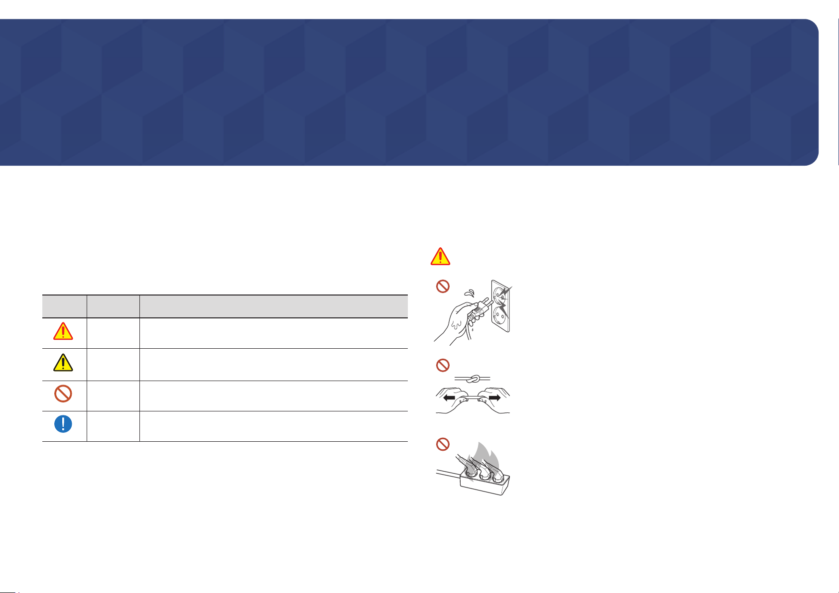
Symbol Name Meaning
Warning
Caution
Prohibition
Instruction
A serious or fatal injury may result if instructions are not followed.
Personal injury or damage to properties may result if instructions
are not followed.
Do NOT attempt.
Follow directions.
Electricity and Safety
"
The following images are for reference only. Real-life situations may differ from what is
shown in the images.
Warning
Do not touch the power plug with wet hands.
Otherwise, an electric shock may result.
Do not bend or pull the power cable with force. Be careful not to
leave the power cable under a heavy object.
Product failure, an electric shock or fire may result from a damaged
cable.
Do not connect multiple products to a single power socket.
Overheated power sockets may cause a fire.
5
Page 6

Insert the power plug all the way in so it is not loose.
An unsecure connection may cause a fire.
Clean any dust around the pins of the power plug or the power socket with a dry cloth.
A fire may result.
Connect the power plug to a grounded power socket. (Except for devices that do not
provide grounding)
An electric shock or injury may result.
Do not use a damaged power plug or a loose power socket.
An electric shock or fire may result.
Caution
Hold the plug when disconnecting the power cable from the power
socket.
An electric shock or fire may result.
When connecting the power plug to the port, be sure to connect it
completely.
If the power plug is not completely connected to the port, the plug
may be unexpectedly disconnected, or there is a risk of overheating
due to overcurrent, leading to safety accidents.
Only use the power cable provided with your product by Samsung. Do not use the
power cable with other products.
An electric shock or fire may result.
Keep the power socket where the power cord is connected unobstructed.
When a problem occurs with the product, the power cord must be unplugged to
completely cut off power to the product. The power is not completely cut off by using
only the Power button on the body of the product.
Do not disconnect the power cable while the product is being used.
The product may become damaged by an electric shock.
6
Page 7
Installation
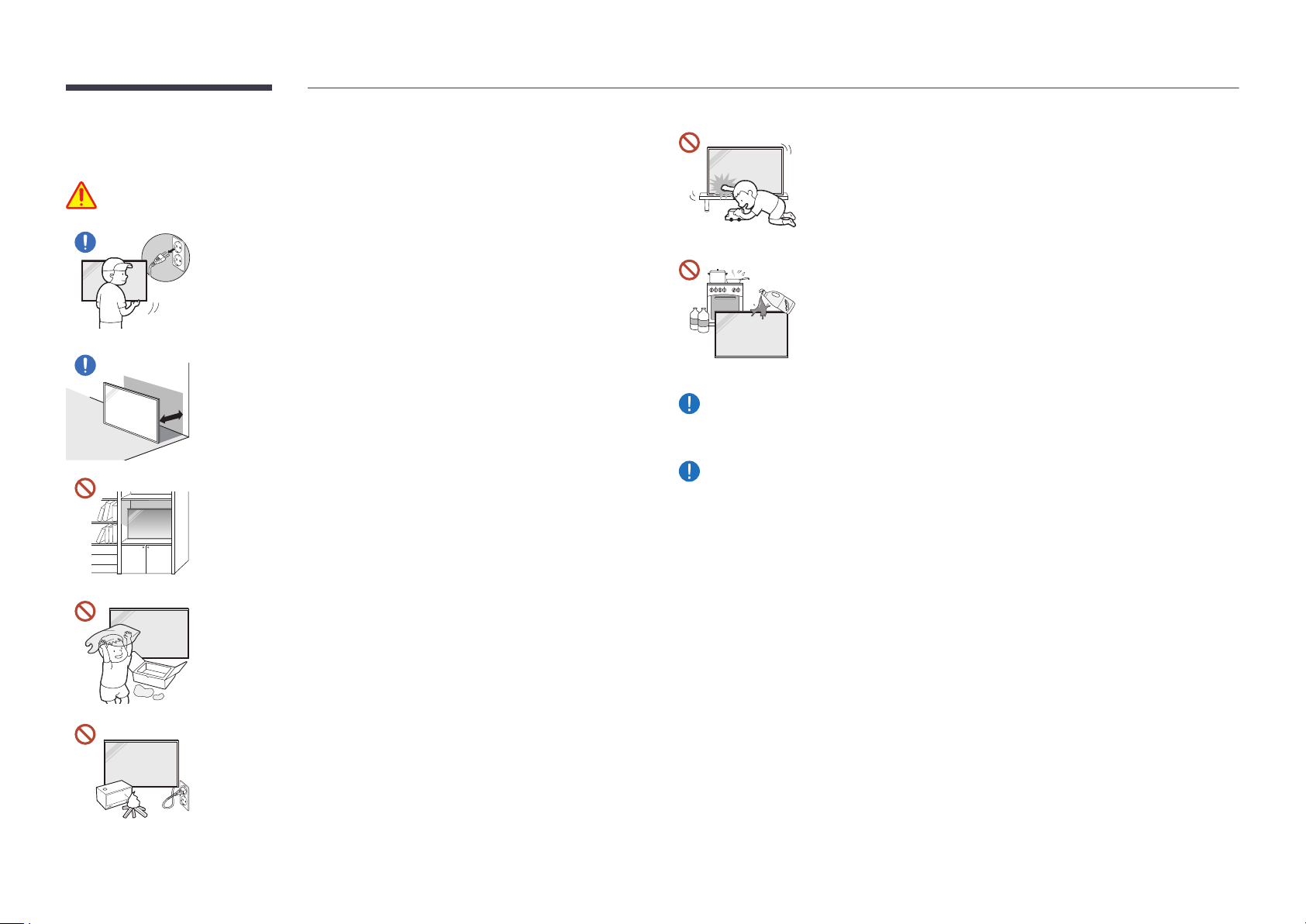
Warning
Before moving the product, turn off the power switch and disconnect
the power cable and all other connected cables.
Damage to the cable may cause a fire or electric shock.
When installing the product, keep it at a distance from the wall so
that it is well ventilated.
An increased internal temperature may cause a fire.
Do not install the product in a poorly ventilated space such as
bookcase or closet.
An increased internal temperature may cause a fire.
Keep the plastic packaging out of the reach of children.
Children's misuse of the plastic packaging may cause suffocation.
When installing the product, fix it firmly so that it does not fall.
If the product is not fixed firmly and a child touches the product while
playing, the product may fall, causing damage to the product or injury
to the child.
Do not install the product in a kitchen or near a kitchen counter.
Edible oil or oil vapor can damage or deform the product.
Have a technician install the wall-mount hanger.
Installation by an unqualified person can result in an injury. Only use approved
cabinets.
If the product is installed in an unusual location, the surrounding environment may
cause a serious quality problem. Therefore, be sure to contact Samsung Customer
Service Center before installation.
(Places where many fine dusts are generated, places where chemicals are used,
places with too high or low temperatures, places with a lot of moisture or water,
transportation equipment such as vehicles, airports and stations used continuously
for a long time, and more)
Do not install the power cable (DC power supply) and the product
near head sources.
(Candles, mosquito repellents, cigarettes, sprays, heating devices,
places exposed to direct sunlight, and more)
7
Page 8
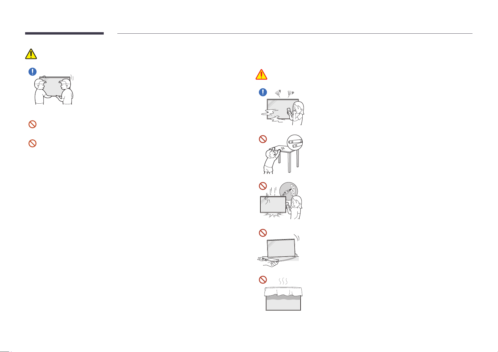
Caution
When lifting and moving the product, do not touch the screen
display, and make sure that at least two people work together.
The product may fall, causing personal injury or product damage.
Do not lay down the product on its front.
The screen may become damaged.
Prolonged exposure to direct sunlight may discolor the surface of the screen display.
Operation
Warning
If the product generates a strange noise, a burning smell, or smoke,
unplug the power plug immediately and contact your Samsung
Customer Service Center.
An electric shock or fire may result.
Keep the remote control batteries and the small accessories out of
the reach of children. Ensure children do not swallow any of them.
If children have had the battery in their mouths, consult your doctor
immediately.
If the product is dropped or its appearance is damaged, turn off the
power switch and disconnect the power cord. Then contact Samsung
Customer Service Center.
Continued use can result in an electric shock or a fire.
Do not move the product by pulling the power cord or any cable.
Product failure, an electric shock or fire may result from a damaged
cable.
Ensure the vents are not blocked by tablecloths or curtains.
An increased internal temperature may cause a fire.
8
Page 9
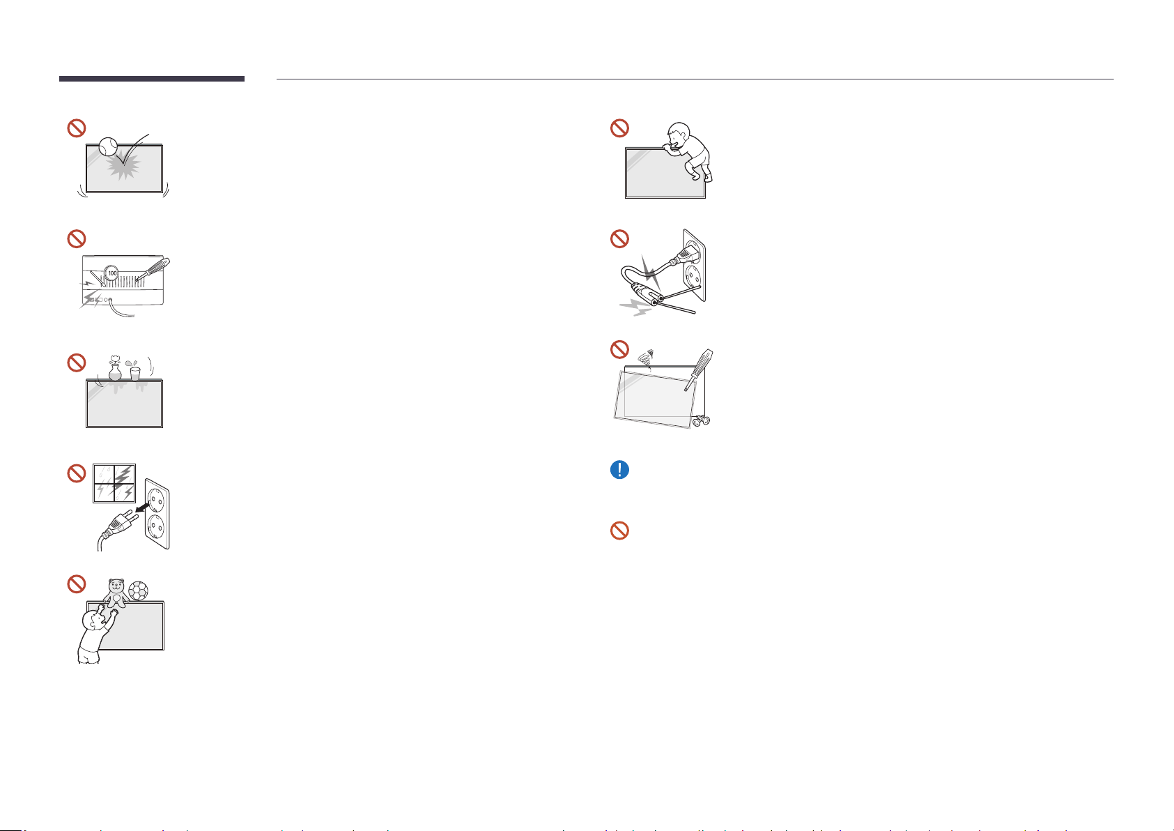
Do not apply an impact to the product.
• The screen display may be damaged.
• An electric shock or fire may result.
Do not hang on or climb on the product.
• The product may fall, causing personal injury or even death.
• Be especially careful that children do not hang on or climb on the
product.
Do not insert metallic objects (chopsticks, coins, hairpins, etc) or
objects that burn easily (paper, matches, etc) into the product (via
the vent or input/output ports, etc).
• If foreign substances enter the product, be sure to power off the
product and disconnect the power cord. Then contact Samsung
Customer Service Center.
• Product failure, an electric shock or fire may result.
Do not place objects containing liquid (vases, pots, bottles, etc) or
metallic objects on top of the product.
• If foreign substances such as water enter the product, be sure
to disconnect the power cord. Then contact Samsung Customer
Service Center.
• Product failure, an electric shock or fire may result.
During a lightning or thunderstorm, power off the product and
disconnect the power cord.
An electric shock or fire may result.
Do not leave heavy objects or items that children like (toys, sweets,
etc.) on top of the product.
The product or heavy objects may fall as children try to reach for the
toys or sweets resulting in a serious injury.
While the power plug is plugged into a power socket, do not insert
a chopstick or other conductor into a remaining power socket. Also,
after disconnecting the power plug from the power socket, do not
touch the pins of the plug immediately.
Otherwise, an electric shock may result.
There is a high voltage inside the product. Never disassemble, repair
or modify the product yourself.
• Contact Samsung Customer Service Center for repairs.
• An electric shock or fire may result.
If a gas leakage is found, do not touch the product or the power plug, and ventilate the
room immediately.
Sparks can cause an explosion or fire.
Do not use humidifiers or stoves around the product.
An electric shock or fire may result.
9
Page 10

Caution
Insert each battery so that its polarity (+, –) is correct.
If the polarity is not correct, the battery may rupture or the
internal fluid may leak, causing contamination and damage to the
surroundings, fire, or personal injury.
Do not place heavy objects on the product.
Product failure or personal injury may result.
When you do not use the product for a long time due to vacation or other reason,
disconnect the power cord from the power socket.
Dust accumulation combined with heat can cause a fire, electric shock or electric
leakage.
Use the product at the recommended resolution and frequency.
Your eyesight may deteriorate.
The batteries (and rechargeable batteries) are not ordinary refuse and must be
returned for recycling purposes. The customer is responsible for returning the used or
rechargeable batteries for recycling.
The customer can return used or rechargeable batteries to a nearby public recycling
center or to a store selling the same type of the battery or rechargeable battery.
Rest your eyes for more than 5 minutes for every 1 hour of product use.
Eye fatigue will be relieved.
Leaving the screen fixed on a stationary image for an extended period of time may
cause afterimage burn-in or defective pixels.
When you do not use the product for a long time, activate power-saving mode or set
the screen saver to moving-picture mode.
Do not use or keep combustible spray or an inflammable substance near the product.
An explosion or fire may result.
Use only the specified standardized batteries, and do not use a new battery and a used
battery at the same time.
Otherwise, the batteries may be damaged or cause fire, personal injury or damage due
to a leakage of the internal liquid.
Do not watch the product screen too closely and continuously for a long time.
Your eyesight may deteriorate.
Do not lift or move the product when it is in operation.
Do not touch the screen when the product has been turned on for an extended period
of time as it will become hot.
When using headphones or earphones, do not turn the volume too high or use them
for a long time.
Damage to your hearing may result.
10
Page 11

Cleaning
Warning
Caution
When cleaning, be sure to disconnect the power plug and wipe gently with a soft and
dry cloth such as superfine fibers or cotton flannels to prevent scratches.
The product's surface may be damaged, or the markings may be erased.
Be sure to use a soft and dry cloth such as superfine fibers or cotton flannels because
the surface of the product and the screen display are vulnerable to scratches.
The product's surface or the screen display can be easily scratched with foreign
substances.
Do not apply chemicals containing alcohol, solvent, or surfactant such as wax,
benzene, thinner, pesticide, air freshener, lubricant, or cleaner to the product.
The product's exterior may be discolored or cracked, the surface of the panel may be
peeled off, or the markings may be erased.
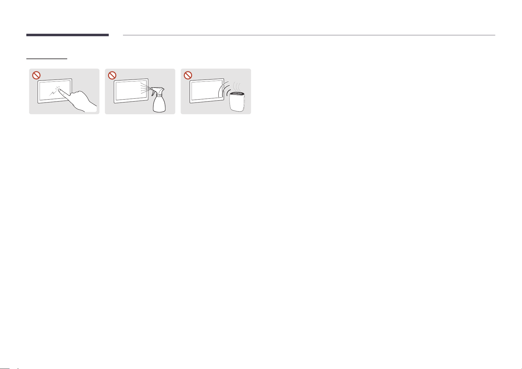
Do not spray water or cleaner directly on the product.
• The product’s surface may be damaged, or the markings may be
erased.
• An electric shock or fire may result.
Storage and Maintenance
"
If dust or dirt from the supplied pen remains on the protective glass, clean it referring to
the instructions below.
Cleaning the exterior and display
Wipe the surface with a slightly wet, soft cloth, and then wipe with a dry cloth.
1 32
11
Page 12
Precautions
Do not scratch the screen
with nails or sharp objects.
Scratches may leave marks or
damage the product.
• Removing a sticker attached on the screen may leave residues. Clean the residues before
watching the screen.
• Do not strongly press and rub the product. Damage to the product may result.
• Do not wipe the screen with chemicals. Product failure may result.
• Contact Customer Service Center if the inside of the product needs cleaning (service fee
will be charged).
Do not spray water directly
on any part of the product.
Product failure, an electric
shock or fire may result from
water that enters the product.
Due to the characteristics of
high-glossy products, using
a UV humidifier nearby may
create white-colored stains
on the product.
Precautions for Use
Be careful that if you use the supplied pen with a load exceeding 2.5 kg, scratches may occur on the
protective glass.
If you use a ballpoint pen other than the supplied pen, be careful that the screen may be stained
with ink or damaged.
"
We recommend that you use the supplied pen. Do not use sharp, pointed objects other than
the pen.
12
Page 13
Chapter 02
Preparations
"Contact the vendor where you
purchased the product if any
components are missing.
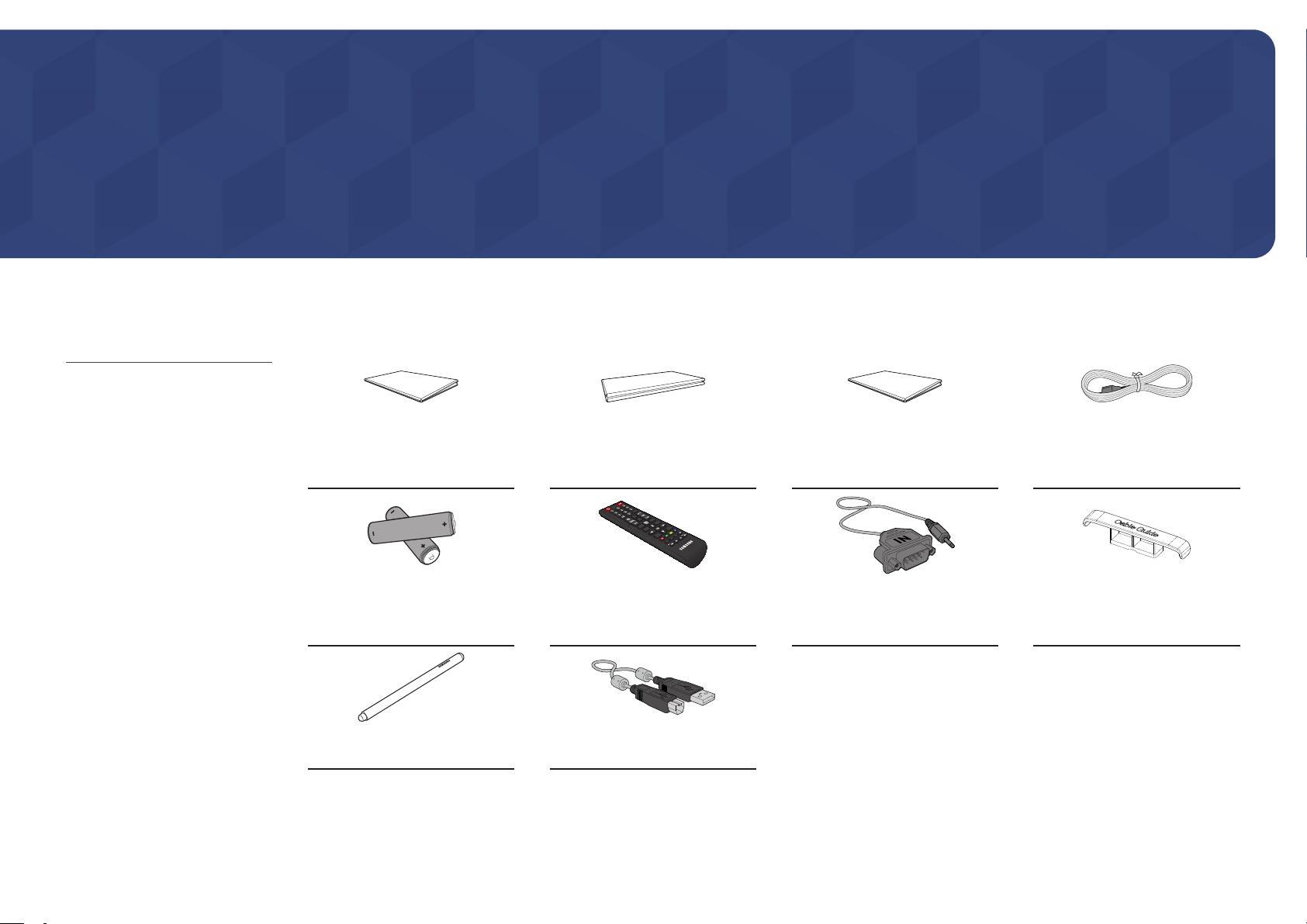
Checking the Components
"The appearance of the components
may differ from the images shown.
"A stand is not provided with the
product. To install a stand, you can
purchase one separately.
"The RS232C adapter can be used to
connect to another monitor using the
D-SUB (9-pin) type RS232C cable.
Quick Setup Guide
Batteries (AAA X 2)
(Not available in some locations)
Touch Pen X 2 USB cable
Warranty card
(Not available in some locations)
Remote Control RS232C(IN) adapter HOLDER-CABLE
Regulatory guide Power cord
13
Page 14
Parts
"
The color and shape of parts may differ from what is shown. Specifications are subject to change without notice
to improve quality.
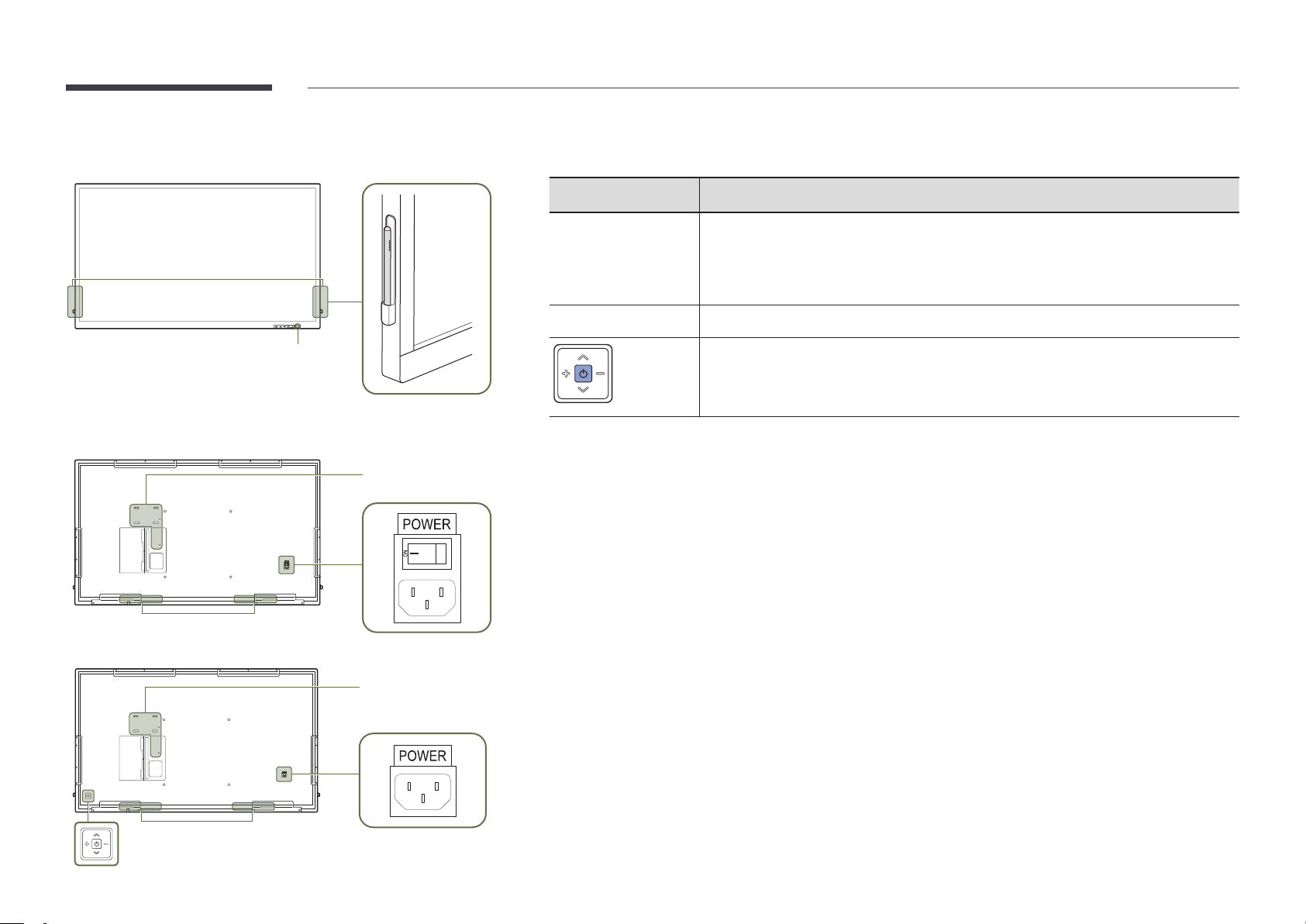
Parts Description
QB65H-TR
QB75H-TR
Speaker
Remote sensor
Pen holder
Network box mounting
hole
Remote sensor
Pen holder
Use the remote control within 7 m to 10 m from the sensor on the product at an angle of 30° from the left and right.
"
Store used batteries out of reach of children and recycle.
"
Do not use a new and used battery together. Replace both batteries at the same time.
"
Remove batteries when the remote control is not to be used for an extended period of time.
Press a button on the remote control pointing at the sensor on the front of the product
to perform the corresponding function.
"
Using other display devices in the same space as the remote control of this product
can cause the other display devices to be inadvertently controlled.
Keep the touch pen in place.
Turns the product on or off.
"
Supported models: QB75H-TR
Panel Key
Network box mounting
hole
Speaker
14
Page 15

Ports
Port Description
"
The color and shape of parts may differ from what is shown.
Specifications are subject to change without notice to improve quality.
USB 1 ¨(1.0A)
RJ45
RS232C IN
DVI/MAGICINFO IN
HDMI IN 1
HDMI IN 2
DP IN
TOUCH OUT 1
USB 2(0.5A)
Connect to a USB memory device.
"
The USB ports on the product accept a maximum constant current of
1.0A. If the maximum value is exceeded, USB ports may not work.
Connects to MDC using a LAN cable. (10/100 Mbps)
"
Use Cat7(*STP Type) cable for the connection.
*Shielded Twist Pair.
Connects to MDC using an RS232C adapter.
DVI: Connects to a source device using a DVI cable or HDMI-DVI cable.
MAGICINFO IN: To use MagicInfo, make sure to connect the DP-DVI cable.
"
To activate MagicInfo, the IWB S5 function must be turned OFF. Please
contact a service center.
Connects to a source device using a HDMI cable or HDMI-DVI cable.
Connects to a PC using a DP cable.
Connects to a PC to use the touch function.
Connect to a USB memory device.
"
The USB ports on the product accept a maximum constant current of
0.5A. If the maximum value is exceeded, USB ports may not work.
DVI/HDMI/AUDIO IN
AUDIO OUT
IR IN
RS232C OUT
Receives sound from a PC via an audio cable.
Connects to the audio of a source device.
Supplies power to the external sensor board or receives the light sensor signal.
Connects to MDC using an RS232C adapter.
15
Page 16
Tray
"
The color and shape of parts may differ from what is shown. Specifications are subject to change without notice to improve quality.
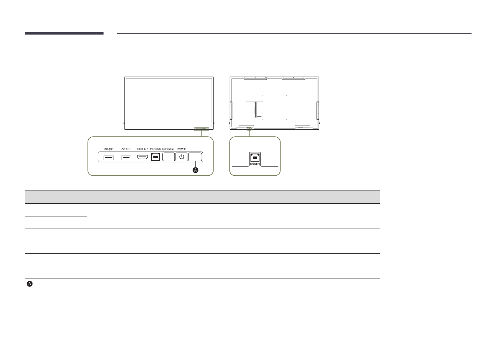
Parts Description
USB (PC)
USB 3
¨
HDMI IN 3
TOUCH OUT 2
QUICK MENU
POWER
Connect to a USB memory device.
Connects to a source device using a HDMI cable or HDMI-DVI cable.
Connects to a PC to use the touch function.
If you press the QUICK MENU button while the screen is on, the main menu appears at the bottom of the screen.
Turns the product on or off.
Press a button on the remote control pointing at the sensor on the front of the product to perform the corresponding function.
16
Page 17
Using the touch function
Anti-theft Lock
"
The color and shape of parts may differ from what is shown. Specifications are subject to
change without notice to improve quality.
USB cable
To use the touch function with a Network box (sold separately) or computer connected to the
1
product, use the USB cable to connect the TOUCH OUT port on the product to the USB port
on the Network box or computer.
If you connect the TOUCH OUT port to a PC that uses multiple monitors, the touch function
2
operates only on the primary monitor.
"
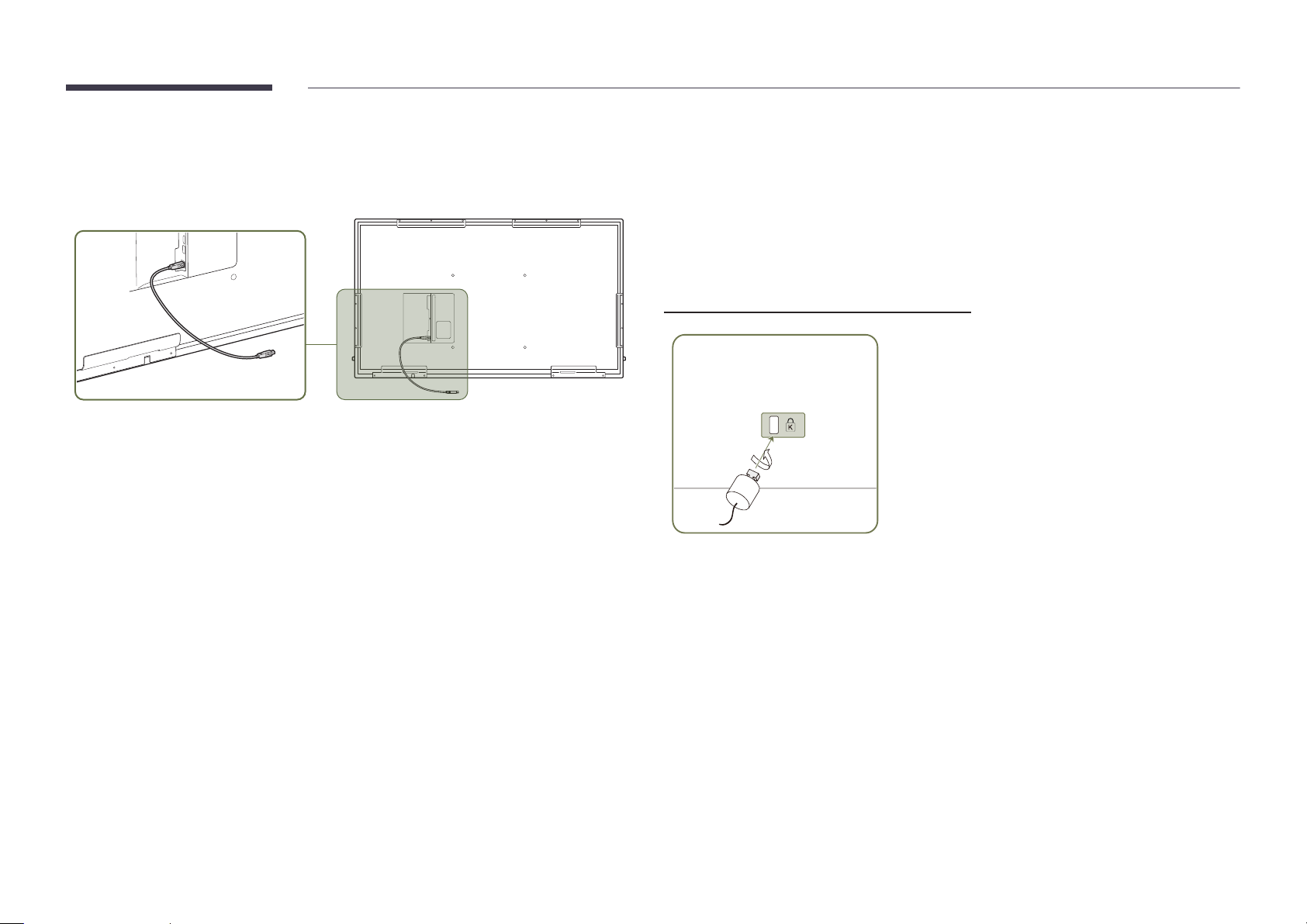
An anti-theft lock allows you to use the product securely even in public places.
"
The locking device shape and locking method depend on the manufacturer. Refer to the user
guide provided with your anti-theft locking device for details.
"
The following images are for reference only. Real-life situations may differ from what is
shown in the images.
To lock an anti-theft locking device:
Fix the cable of your anti-theft locking device to a heavy object such as a desk.
1
Put one end of the cable through the loop on the other end.
2
Insert the locking device into the anti-theft lock slot at the back of the product.
3
Lock the locking device.
4
– An anti-theft locking device can be purchased separately.
– Refer to the user guide provided with your anti-theft locking device for details.
– Anti-theft locking devices can be purchased at electronics retailers or online.
17
Page 18

HOME
CH
MagicInfo
Player I
DEL-/--
CH LIST
Remote Control
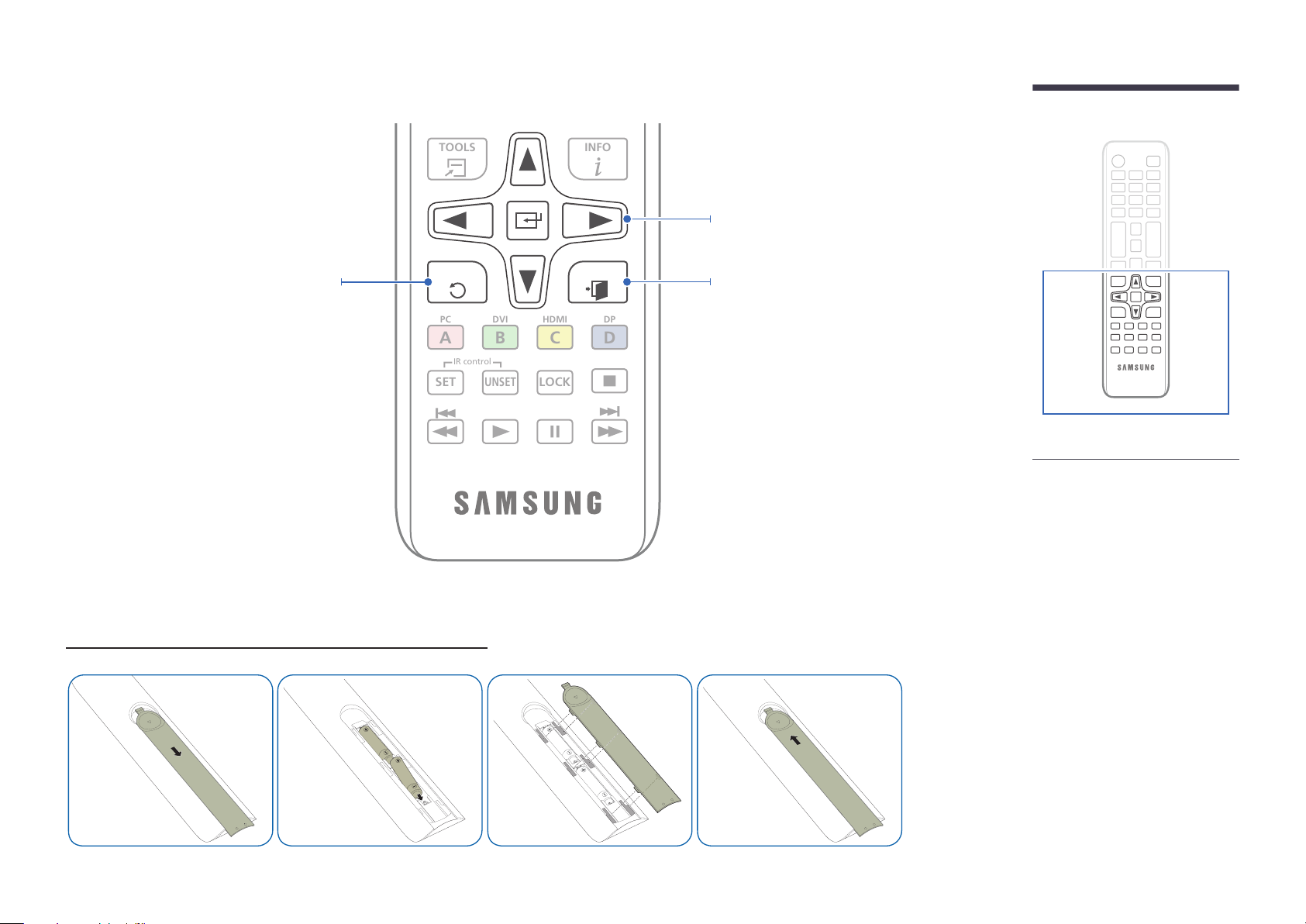
"
Using other display devices in the same space as the remote control of this product can cause the other display devices to be inadvertently controlled.
"
A button without a description in the image below is not supported on the product.
Power on the product.
Adjust the volume.
Open Launch Button.
Display or hide the onscreen display menu, or
return to the previous menu.
.QZ
1
GHI
4
PRS
7
VOL
MENU
ABC
2
JKL
5
TUV
8
SYMBOL
0
MUTE
SOURCE
POWER
OFF
DEF
3
MNO
6
WXY
9
Power off the product.
Number buttons
Enter the password in the OSD menu.
Mute the sound.
• Unmuting the sound: Press MUTE again
or press the volume control(+ VOL -)
button.
"Remote control button functions
may differ for different products.
18
Page 19
TOOLS
INFO
SET
UNSET
LOCK
PCADVIBHDMICDP
D
IR control
Move to the upper, lower, left or right menu,
or adjust an option's setting.
Confirm a menu selection.
Return to the previous menu.
To place batteries in the remote control (AAA x 2)
EXITRETURN
Exit the current menu.
"Remote control button functions
may differ for different products.
"Remove batteries when the remote
control is not to be used for an
extended period of time.
19
Page 20
Installing the Wall Mount
Installing the Wall Mount
• The wall mount kit (sold separately) allows you to mount the product on the wall.
• For detailed information on installing the wall mount, see the instructions provided with the wall mount.
• We recommend you contact a technician for assistance when installing the wall mount bracket.
• Samsung Electronics is not responsible for any damage to the product or injury to yourself or others if you elect to install the wall mount on your own.
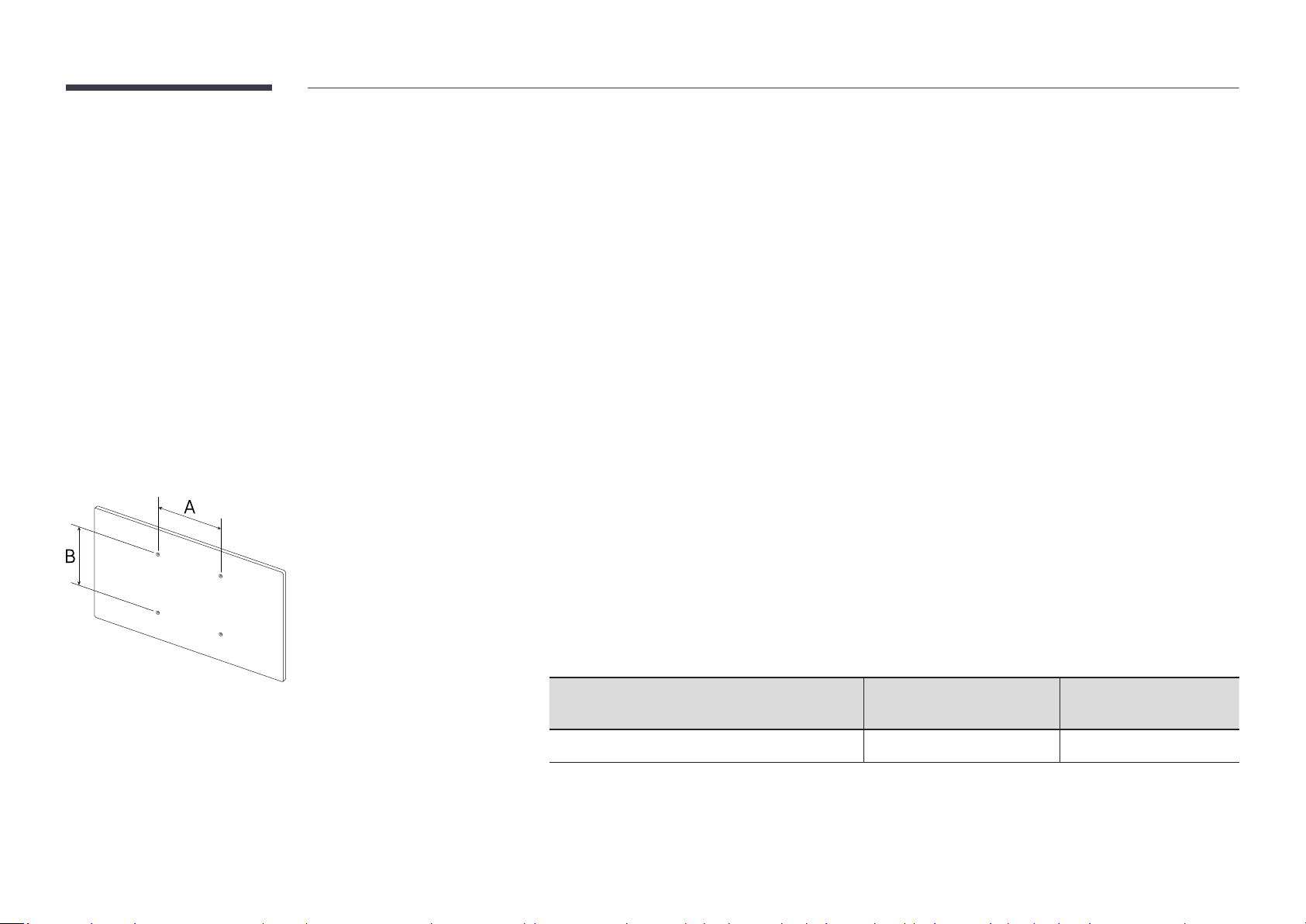
Wall Mount Kit Specications (VESA)
"
Install your wall mount on a solid wall perpendicular to the floor. To
install the product on the other wall area, contact the nearest agency.
If you install the product on a slanted wall, it may fall and result in
severe personal injury.
• Samsung wall mount kits contain a detailed installation manual and all parts necessary for assembly are
provided.
• Do not use screws that are longer than the standard length or do not comply with the VESA standard screw
specifications. Screws that are too long may cause damage to the inside of the product.
• For wall mounts that do not comply with the VESA standard screw specifications, the length of the screws may
differ depending on the wall mount specifications.
• Do not fasten the screws too firmly. This may damage the product or cause the product to fall, leading to
personal injury. Samsung is not liable for these kinds of accidents.
• Samsung is not liable for product damage or personal injury when a non-VESA or non-specified wall mount is
used or the consumer fails to follow the product installation instructions.
• Do not mount the product at more than a 15 degree tilt.
• Always have at least two people mount the product on a wall.
• Standard dimensions for wall mount kits are shown in the table below.
VESA screw hole specs (A * B) in
millimeters (inches)
400 × 400 (15.7 × 15.7) M8 4
"
Do not install your Wall Mount Kit while your product is turned on. It may result in personal injury due to electric
shock.
Standard Screw Quantity
20
Page 21
Chapter 03
Using a touchscreen monitor
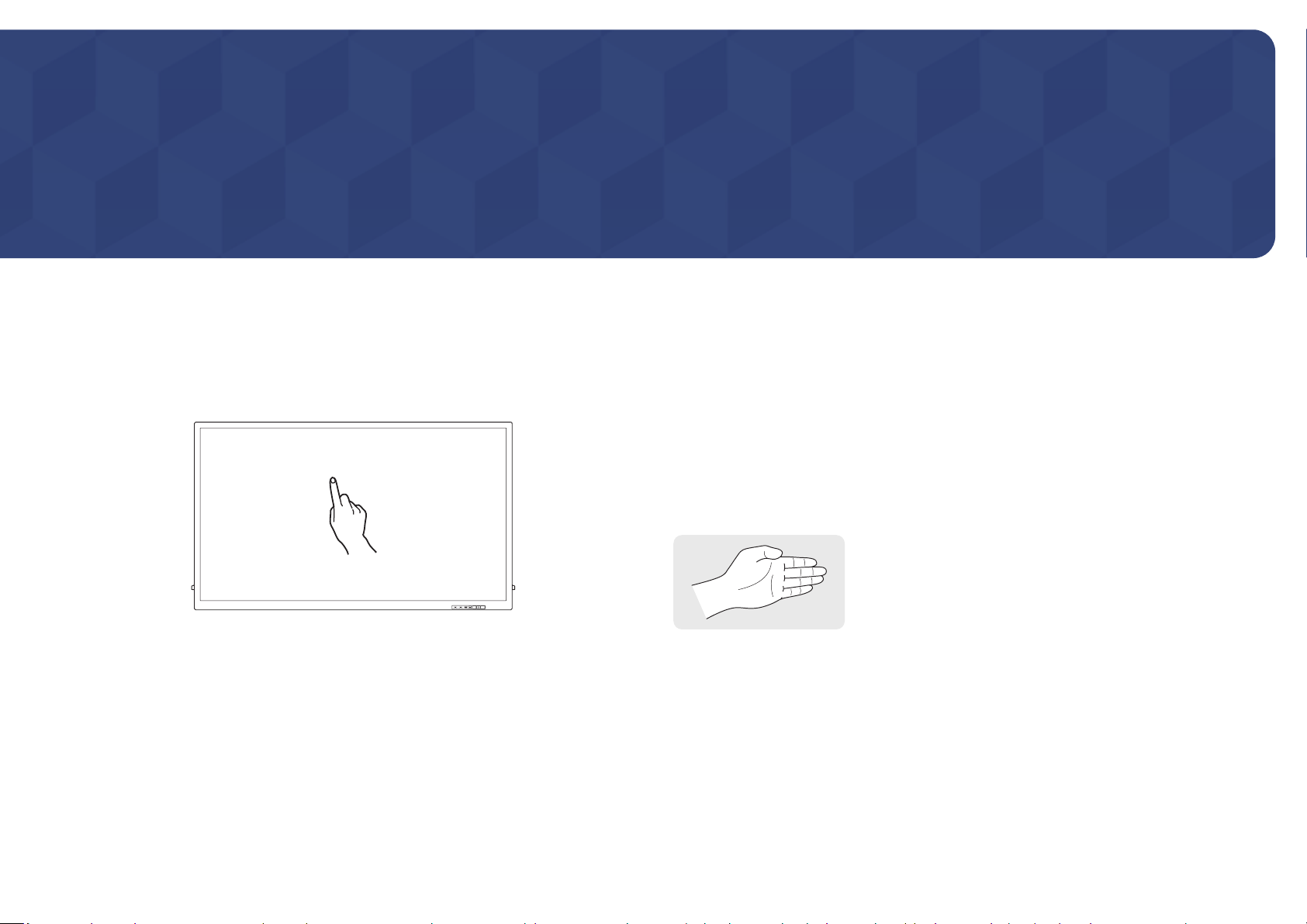
Touchscreen monitor
Control a PC by tapping the screen instead of using an input device such as a keyboard or mouse.
The touch screen functions by detecting a minute electric current that runs through your body
(capacitive). Make sure to use the surface of your finger tip when tapping the screen.
Read below before using the product
• Take extra care to ensure an electrical substance does not contact the screen. The screen
may not function properly if there is static.
• Do not press hard on the touch screen with your finger tip. Do not use a sharp object when
tapping the screen. The screen may break or get damaged.
• Do not tap the screen while wearing a glove, with a dirty finger, or using something sharp
such as your fingernail or a ballpoint pen. The screen may not function properly.
• Take extra care to ensure the screen does not contact moisture. The touch sensor may not
function properly.
• Displaying a still image on the screen for an extended period of time may cause after images
(screen degradation) or stains. Switch off the screen when not in use.
• When using your palm as an eraser, put your fingers
together.
21
Page 22
Connecting the touchscreen monitor
Connecting to a PC
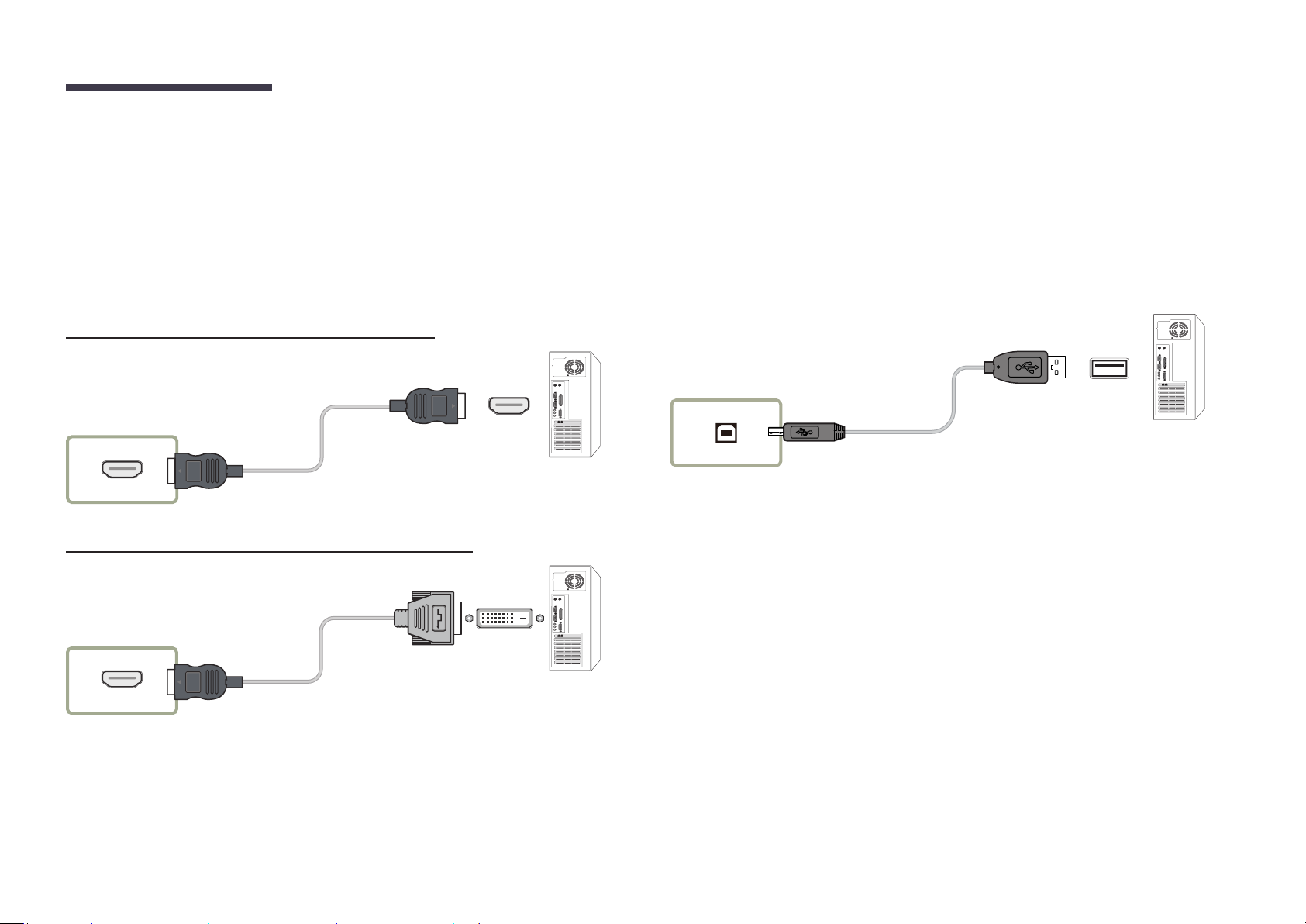
Connect your PC to the product using a HDMI or HDMI-DVI cable.
1
"
Connecting parts may differ in different products.
Connecting the devices using a HDMI cable
HDMI IN 1, HDMI IN 2, HDMI IN 3
Connect the power cable from the product to the power outlet.
2
After the power supply is connected, the product automatically detects and switches to the
3
connected input source.
"
If the screen appears blank, turn the product off and then on again.
Connect the TOUCH OUT port on the product to a USB port on the PC using the USB cable.
4
"
TOUCH OUT 1 operates when the current screen is set to HDMI 1, HDMI 2, DisplayPort, or
DVI.
"
TOUCH OUT 2 operates when the current screen is set to HDMI 3.
TOUCH OUT 1, TOUCH OUT 2
Connecting to a laptop or tablet PC
Connecting the devices using a HDMI-DVI cable
HDMI IN 1, HDMI IN 2, HDMI IN 3
A laptop or tablet PC can be connected to the product using the same method when connecting
a desktop PC.
• If touchscreen control is not available after the devices are connected
"
Make sure to connect the HDMI or HDMI-DVI cable before connecting the USB cable.
"
If touchscreen control is still unavailable after the cables are connected properly,
disconnect the USB cable and then connect it again.
22
Page 23
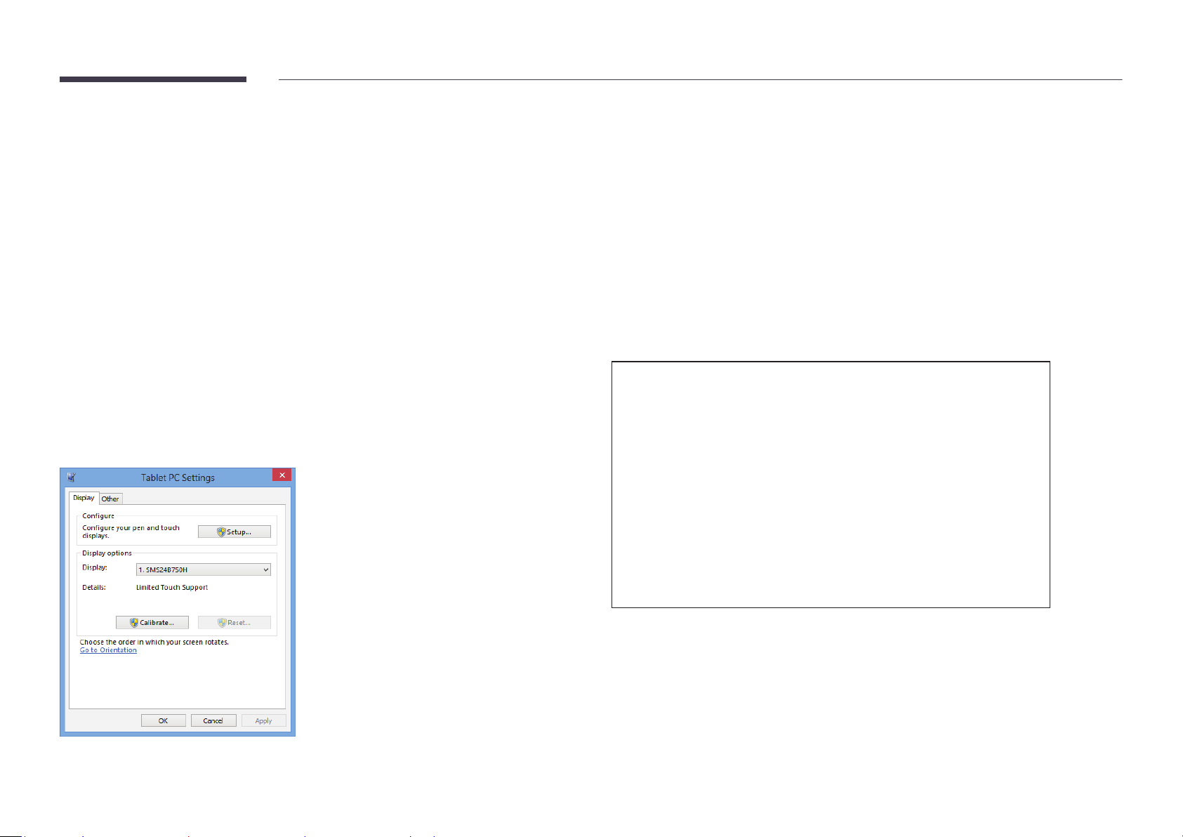
Conguring the touchscreen monitor settings
To properly use the touch function of the product in Windows, go to Tablet PC Settings and calibrate the product.
"
First connect the touchscreen monitor before configuring the following settings.
"
The maximum number of touchscreen monitors that can be connected simultaneously varies, depending on the operating system and graphics card settings.
"
If Tablet PC Settings is not found in the Control Panel, search for Search Control Panel for Tablet PC Settings.
Tap the page displayed on the product with your finger.
Calibration
"
Instructions below are for Windows 8. The same method applies to both Windows 7,
Windows 8 and Windows 10.
"
After changing the Picture Size from the OSD menu, you may need to calibrate the picture
settings again.
"
In the occurrence of an error during calibration, go to Tablet PC Settings → the Display tab.
Tap Reset, and calibrate again.
In the Display tab, select Setup under Configure.
1
2
"
In dual monitor mode: If the following page does not appear on the product, press the
Enter key to display the page.
Touch this screen to identity it as the touchscreen.
If this is not the Tablet PC screen, press Enter to move to the next screen. To close the tool, press Esc.
23
Page 24

Select the product from Display under Display options. Next, select Calibrate.
3
Perform calibration following the onscreen instructions displayed as shown in the image.
4
After calibration is complete, the message Do you want to save the calibration data?
5
appears. Select Yes to save changes.
Digitizer Calibration Tool
Do you want to save the calibration data?
Yes No
The touchscreen monitor has been calibrated successfully.
6
"
Selecting Reset will remove the calibration data.
To provide calibration samples, tap the crosshair each
time that it appears on the screen.
Right-click anywhere on the screen to return to the
last calibration point. Press the Esc button to close
the tool. Do not change your screen orientation until
you have completed the calibration process.
24
Page 25
Controlling the screen
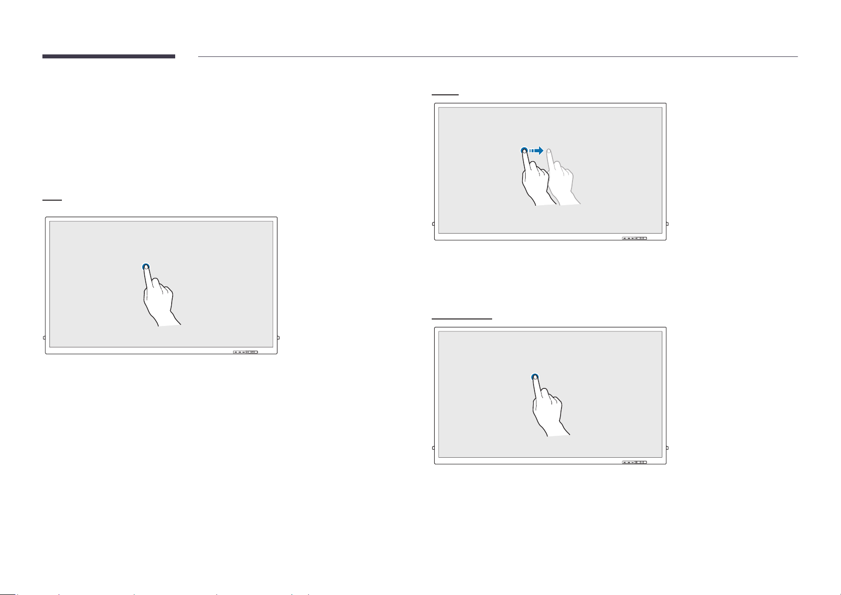
Touchscreen gestures
Using touchscreen gestures is similar to using a mouse.
Tap
Lightly tap the screen.
Use this gesture to select a feature or menu item.
"
It is similar to clicking on a mouse.
Drag
Lightly touch and drag in any direction on the screen.
Use this gesture to move in a specific direction on a web page, map or photo.
"
It is similar to dragging a mouse.
Double tap
Tap the screen twice.
Use this gesture to run the selected program.
"
It is similar to double-clicking on a mouse.
25
Page 26
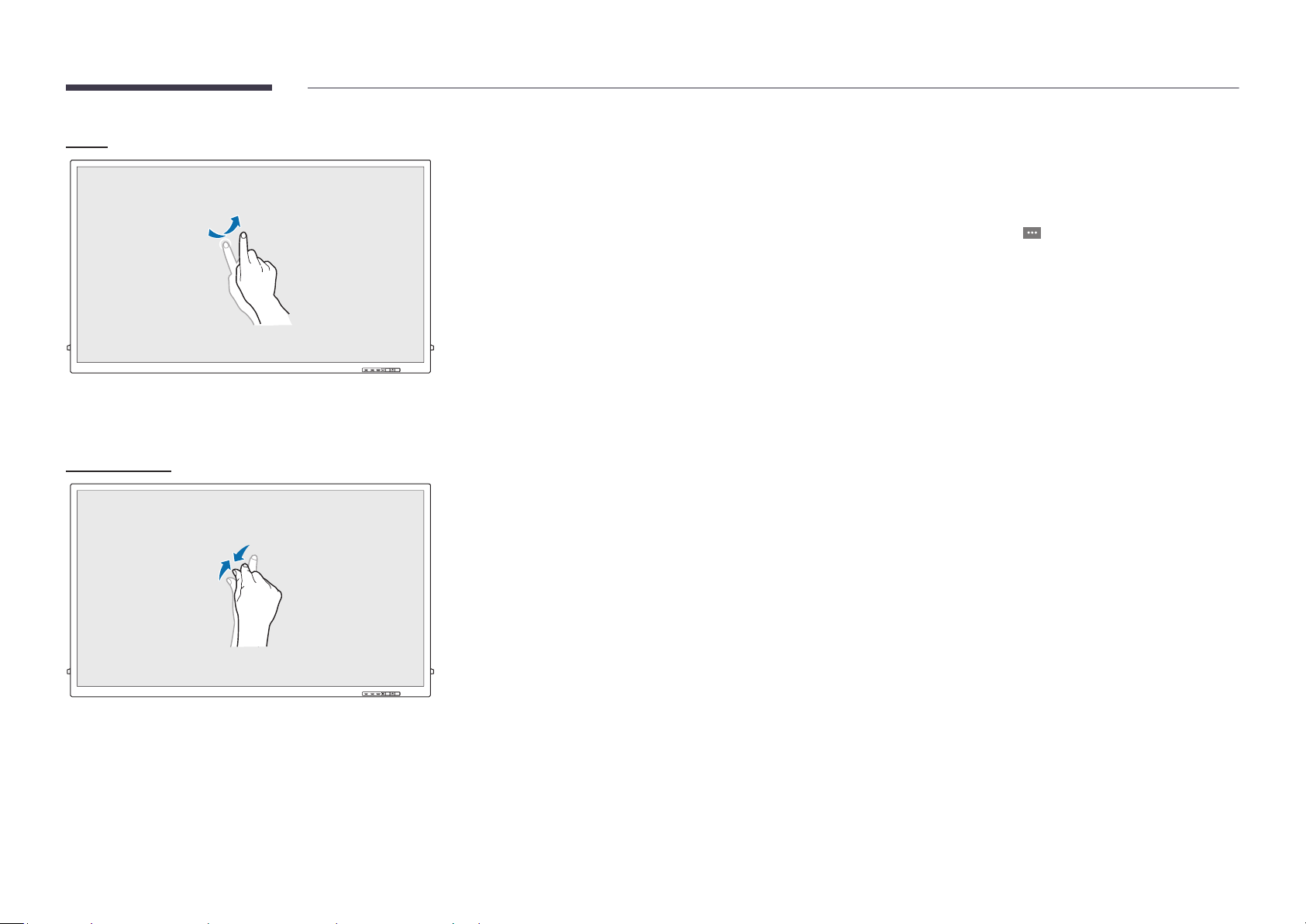
Flick
Flick your finger on the screen as shown in the image.
Use this gesture to go to the previous or next picture or web page.
Zoom in/out
Notes
• To increase the touch input accuracy, enlarge the font or icons.
• In touchscreen control mode, use of the remote control when precise clicks or inputs are
required is more effective.
• For details on how to use the Whiteboard icons, tap the
and then tap Quick Guide.
icon at the bottom of the screen,
Spread or pinch your fingers on the screen as shown in the image.
Use these gestures to zoom in or out respectively on a web page, map or photo.
26
Page 27

Chapter 04
Connecting and Using a Source Device
Before Connecting
Pre-connection Checkpoints
"
Before connecting a source device, read the user manual provided with it.
The number and locations of ports on source devices may differ from device to device.
"
Do not connect the power cable until all connections are completed.
Connecting the power cable during connection may damage the product.
"
Connect the sound ports correctly: left = white and right = red.
"
Check the types of ports at the back of the product you want to connect.
"
We recommend using authorized cables for HDMI or DP cable connections.
Connecting to a PC
• Do not connect the power cable before connecting all other cables.
Ensure you connect a source device first before connecting the power cable.
• A PC can be connected to the product in a variety of ways.
Select a connection method suitable for your PC.
"
Connecting parts may differ in different products.
Connection Using an HDMI Cable
HDMI IN 1, HDMI IN 2, HDMI IN 3
27
Page 28

Connection Using an DP Cable
DP IN
Connection using a DVI cable (Digital type)
DVI/MAGICINFO IN
• Precautions for using DP
"
Some graphics cards that are not compliant with the DP standard may prevent the
Windows Booting/Bios screen from being displayed when the product is in power-saving
mode. If this is the case, make sure to turn on the product first before turning on your
PC.
"
The interface DP IN on the product and the provided DP cable are designed based on the
VESA standards. Using a DP cable that is not VESA compliant may cause the product to
function improperly. Samsung Electronics shall not be held responsible for any issues
from using a cable that is not VESA compliant.
Make sure to use a DP cable that is VESA compliant.
"
To use the optimal resolution (3840x2160 @ 60Hz) when the input source is DisplayPort,
using a DP cable shorter than 5m is recommended.
"
Disabling power-saving mode when the input source is DisplayPort may import new
resolution information and reset the task window size or location.
DVI/HDMI/AUDIO IN
"
You can use the DVI port on the product as an HDMI port by using a DVI-HDMI adapter.
"
Audio is not available if the DVI port on the product is connected to the HDMI port on the PC
using a DVI-HDMI adapter.
DVI/MAGICINFO IN
HDMI
28
Page 29
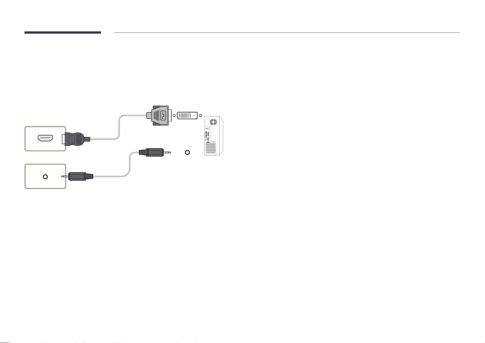
Connection Using an HDMI-DVI Cable
After connecting a computer to the product with an HDMI-DVI cable, make sure to configure the
settings as shown below to enable the video and audio from the computer.
• Sound → set HDMI Sound to PC(DVI)
• Picture → set each screen mode to Text under Picture Mode
• System → General → set HDMI Hot Plug to Off
HDMI IN 1, HDMI IN 2, HDMI IN 3
DVI/HDMI/AUDIO IN
29
Page 30

Connecting to a Video Device
• Do not connect the power cable before connecting all other cables.
Ensure you connect a source device first before connecting the power cable.
• You can connect a video device to the product using a cable.
"
Connecting parts may differ in different products.
"
If using the remote control, connect an external device and press SOURCE on the remote control to select the device.
"
When using the touch function, connect the external device to the product, tap Open, and then select the connected external device while the product is turned on.
Connection Using an HDMI-DVI Cable
• Audio will not be enabled if the product is connected to a video device using an HDMI-DVI
cable. To resolve this, additionally connect an audio cable to the audio ports on the product
and video device.
• After connecting a video device to the product with an HDMI-DVI cable, make sure to
configure the settings as shown below to enable the video and audio from the video device.
You can use the DVI port on the product as an HDMI port by using a DVI-HDMI adapter. Audio
is not available if the DVI port on the product is connected to the HDMI port on the PC using
a DVI-HDMI adapter.
– Sound → set HDMI Sound to AV(HDMI)
– Picture → set each screen mode to Video/Image under Picture Mode
– System → General → set HDMI Hot Plug to On
"
Supported resolutions include 1080p (50/60Hz), 720p (50/60Hz), 480p, and 576p.
HDMI IN 1, HDMI IN 2, HDMI IN 3
DVI/HDMI/AUDIO IN
DVI/MAGICINFO IN
HDMI
30
Page 31

Connection Using an HDMI Cable
Using an HDMI cable or HDMI to DVI Cable (UHD 30Hz)
• An HDMI cable supports digital video and audio signals, and does not require an audio cable.
• The picture may not display normally (if at all) or the audio may not work if an external
device that uses an older version of HDMI mode is connected to the product. If such a
problem occurs, ask the manufacturer of the external device about the HDMI version and, if
out of date, request an upgrade.
• Be sure to use an HDMI cable with a thickness of 14 mm or less.
• Be sure to purchase a certified HDMI cable. Otherwise, the picture may not display or a
connection error may occur.
• A basic high-speed HDMI cable or one with ethernet is recommended.
This product does not support the ethernet function via HDMI.
HDMI IN 1, HDMI IN 2, HDMI IN 3
Connecting to an Audio System
"
Connecting parts may differ in different products.
AUDIO OUT
31
Page 32

Changing the Input source
Applications
• IWB S5 / Screen Mirroring / Web Browser
Open
• Using the remote control: SOURCE
• Using touchscreen control mode: Open
Open
Applications
IWB S5
Source
HDMI 1
Storage
Screen
Mirroring
HDMI 2 HDMI 3 DisplayPort DVI
Web Browser
Source
Source allows you to select a variety of sources and change source device names.
You can display the screen of a source device connected to the product. Select a source from source list to display
the screen of the selected source.
"
If using the remote control, connect an external device and press SOURCE on the remote control to select the
device.
"
When using the touch function, connect the external device to the product, tap Open, and then select the
connected external device while the product is turned on.
"
The screen may not display correctly if an incorrect source is selected for the source device you want to convert
to.
• HDMI 1 / HDMI 2 / HDMI 3 / DisplayPort / DVI
Storage
• Internal Storage / USB
Internal
Storage
"The displayed image may differ depending on the model.
USB
32
Page 33

Chapter 05
Multiple Display Control
Control multiple display devices connected to a PC simultaneously.
Cable Connection
RS232C Cable
Interface
Pin
Bit rate
Data bits
Parity
Stop bit
Flow control
Maximum length
RS232C (9 pins)
TxD (No.2), RxD (No.3), GND (No.5)
9600 bps
8 bit
None
1 bit
None
15 m (only shielded type)
• Pin assignment
Pin Signal
1
Detect data carrier
2
Received data
3
Transmitted data
4
Prepare data terminal
5
Signal ground
1 2 3 4 5
6 7 8 9
<Male type> <Female type>
5 4 3 2 1
9 8 7 6
Pin Signal
6
Prepare data set
7
Send request
8
Clear to send
9
Ring indicator
33
Page 34

• RS232C cable
Connector: 9-Pin D-Sub to Stereo Cable
16
5
9
-P1-
-P1- -P1- -P2- -P2-
3
2
1
-P2-
LAN Cable
• Pin assignment
1 2 3 4 5 6 7 8
Male type
Rx 3
Tx 2
Gnd 5
1 Tx STEREO
2 Rx PLUG
3 Gnd (3.5ø)
Pin No Standard Color Signal
1
2
3
4
5
6
7
8
White and orange TX+
Orange TX-
White and green RX+
Blue NC
White and blue NC
Green RX-
White and brown NC
Brown NC
34
Page 35

• Connector : RJ45
Direct LAN cable (PC to HUB)
HUB
Cross LAN cable (PC to PC)
RJ45
RJ45
P1P2
P1 P2
RJ45
P1
P2
Signal P1 P2 Signal
TX+ 1
TX- 2
RX+ 3
RX- 6
1 TX+
2 TX-
3 RX+
6 RX-
Signal P1 P2 Signal
TX+ 1
TX- 2
RX+ 3
RX- 6
3 RX+
6 RX-
1 TX+
2 TX-
35
Page 36

Connection
"
Ensure you connect each of the adapters to the correct RS232C IN or OUT port on the
product.
• Connection 1
PC
Monitor 1 Monitor 2 Monitor 3 Monitor 4
RS232C IN RS232C OUT RS232C IN RS232C OUT RS232C IN RS232C OUT RS232C IN RS232C OUT
• Connection 2
• Connection 3
PC
PC
Monitor 2Monitor 1
RJ45RJ45 RJ45 RJ45
Monitor 1 Monitor 2 Monitor 3 Monitor 4
Monitor 3
RJ45
RS232C OUT RS232C IN RS 232C OUT RS232C IN RS232C OUT RS232C IN RS 232C OUTRJ45
36
Page 37

Control Codes
Viewing control state (Get control command)
• All communications take place in hexadecimals. The checksum is calculated by adding up
all values except the header. If a checksum adds up to be more than 2 digits as shown below
(11+FF+01+01=112), the first digit is removed.
E.g. Power On & ID=0
Header Command ID Data length Checksum
0xAA Command type 0
Controlling (Set control command)
Header Command ID Data length Data Checksum
0xAA Command type 1 Value
Command
No. Command type Command Value range
1
2
3
4
5
Power control 0x11 0~1
Volume control 0x12 0~100
Input source control 0x14 -
Screen size control 0x19 0~255
Safety Lock 0x5D 0~1
Header Command ID Data length Data 1 Checksum
0xAA 0x11 1 "Power"
Header Command ID Data length Data 1 12
0xAA 0x11 1 1
• To control all devices connected by a serial cable simultaneously irrespective of IDs, set the
ID as "0xFE" and transmit commands. Commands will be executed by each device but ACK
will not respond.
37
Page 38

Power control
Volume control
• Function
A product can be powered on and off using a PC.
• Viewing power state (Get Power ON / OFF Status)
Header Command ID Data length Checksum
0xAA 0x11 0
• Setting power ON/Off (Set Power ON / OFF)
Header Command ID Data length Data Checksum
0xAA 0x11 1 "Power"
"Power": Power code to be set on a product.
1: Power ON
0: Power OFF
• Ack
Header Command ID Data length Ack/Nak r-CMD Val1 Checksum
0xAA 0xFF 3 'A' 0x11 "Power"
"Power": Power code to be set on a product.
• Nak
Header Command ID Data length Ack/Nak r-CMD Val1 Checksum
0xAA 0xFF 3 'N' 0x11 "ERR"
• Function
The volume of a product can be adjusted using a PC.
• Viewing volume state (Get Volume Status)
Header Command ID Data length Checksum
0xAA 0x12 0
• Setting the volume (Set Volume)
Header Command ID Data length Data Checksum
0xAA 0x12 1 "Volume"
"Volume": Volume value code to be set on a product. (0-100)
• Ack
Header Command ID Data length Ack/Nak r-CMD Val1 Checksum
0xAA 0xFF 3 'A' 0x12 "Volume"
"Volume": Volume value code to be set on a product. (0-100)
• Nak
Header Command ID Data length Ack/Nak r-CMD Val1 Checksum
0xAA 0xFF 3 'N' 0x12 "ERR"
"ERR" : A code showing what error has occurred.
"ERR" : A code showing what error has occurred.
38
Page 39

Input source control
• Function
The input source of a product can be changed using a PC.
• Viewing input source state (Get Input Source Status)
Header Command ID Data length Checksum
0xAA 0x14 0
• Setting the input source (Set Input Source)
Header Command ID Data length Data Checksum
• Ack
Header Command ID Data length Ack/Nak r-CMD Val1 Checksum
0xAA 0xFF 3 'A' 0x14 "Input
Source"
"Input Source": An input source code to be set on a product.
• Nak
Header Command ID Data length Ack/Nak r-CMD Val1 Checksum
0xAA 0xFF 3 'N' 0x14 "ERR"
0xAA 0x14 1 "Input Source"
"Input Source": An input source code to be set on a product.
0x18 DVI
0x0C Input source
0x20 MagicInfo
0x1F DVI_video
0x21 HDMI1
0x22 HDMI1_PC
0x23 HDMI2
0x24 HDMI2_PC
0x25 DisplayPort
"
DVI_video, HDMI1_PC and HDMI2_PC cannot be used with the Set command. They only
respond to "Get" commands.
"
MagicInfo is only available with models that contain the MagicInfo function.
"ERR" : A code showing what error has occurred.
39
Page 40

Screen size control
Safety Lock
• Function
The screen size of a product can be changed using a PC.
• Viewing the screen size (Get Screen Size Status)
Header Command ID Data length Checksum
0xAA 0x19 0
• Ack
Header Command ID Data
length
0xAA 0xFF 3 'A' 0x19 "Screen Size"
"Screen Size": product screen size (range: 0 – 255, unit: inch)
• Nak
Header Command ID Data
length
0xAA 0xFF 3 'N' 0x19 "ERR"
"ERR": A code showing what error has occurred
Ack/Nak r-CMD Val1 Checksum
Ack/Nak r-CMD Val1 Checksum
• Function
PC can be used to turn the Safety Lock On function on or off on a product.
This control is available regardless of whether or not the power is turned on.
• Viewing the safety lock state (Get Safety Lock Status)
Header Command ID Data length Checksum
0xAA 0x5D 0
• Enabling or disabling safety lock (Set Safety Lock Enable / Disable)
Header Command ID Data length Data Checksum
0xAA 0x5D 1 "Safety Lock"
"Safety Lock": Safety lock code to be set on a product
1: ON
0: OFF
• Ack
Header Command ID Data
length
0xAA 0xFF 3 'A' 0x5D "Safety Lock"
"Safety Lock": Safety lock code to be set on a product
• Nak
Header Command ID Data
length
Ack/Nak r-CMD Val1 Checksum
Ack/Nak r-CMD Val1 Checksum
0xAA 0xFF 3 'N' 0x5D "ERR"
"ERR": A code showing what error has occurred
40
Page 41

Using MDC
Multiple display control "MDC" is an application that allows you to easily control multiple
display devices simultaneously using a PC.
For details on how to use the MDC program, refer to Help after installing the program. The MDC
program is available on the website.
"
If you press the On or Off button located at the top left of the screen, the product checks its
status for about one minute. To run other commands, try after the one minute.
"
For details on how to connect devices for multiple display control, refer to page 36.
MDC Program Installation/Uninstallation
Installation
"
MDC installation can be affected by the graphics card, mother board and network
conditions.
Click the MDC Unified installation program.
1
Select a language for installation. Next, click "OK".
2
When the "Welcome to the InstallShield Wizard for MDC_Unified" screen appears, click
3
"Next".
Click "Finish" in the displayed "InstallShield Wizard Complete" window.
9
"
Select "Launch MDC Unified" and click "Finish" to run the MDC program immediately.
The MDC Unified shortcut icon will be created on the desktop after installation.
10
"
The MDC execution icon may not be displayed depending on the PC system or product
specifications.
"
Press F5 if the execution icon is not displayed.
Uninstallation
Select Settings > Control Panel on the Start menu and double-click Add/Delete Program.
1
Select MDC Unified from the list and click Change/Remove.
2
In the "License Agreement" window displayed, select "I accept the terms in the license
4
agreement" and click "Next".
In the displayed "Customer Information" window, fill out all the information fields and click
5
"Next".
In the displayed "Destination Folder" window, select the directory path you want to install
6
the program in and click "Next".
"
If the directory path is not specified, the program will be installed in the default
directory path.
In the displayed "Ready to Install the Program" window, check the directory path to install
7
the program in and click "Install".
Installation progress will be displayed.
8
41
Page 42

Chapter 06
Screen Adjustment
Configure the Picture settings (Backlight, Color Tone, etc.).
The layout of the Picture menu options may vary depending on the product.
Picture Mode
MENU m → Picture → Picture Mode → ENTER E
Picture
Picture Mode Shop & Mall
·
Backlight
·
Contrast
·
Brightness
·
Sharpness
·
Color
·
Tint (G/R)
"The displayed image may differ depending on the model.
100
G50 / R50
70
45
65
50
Select a picture mode (Picture Mode) suitable for the environment where the product will be used.
Video/Image mode improves the picture quality of the video device. Text mode improves the picture quality of the
computer.
• Shop & Mall
Suitable for shopping malls.
– Select either Video/Image or Text depending on the picture mode.
• Office & School
Suitable for offices and schools.
– Select either Video/Image or Text depending on the picture mode.
• Terminal & Station
Suitable for bus terminals and train stations.
– Select either Video/Image or Text depending on the picture mode.
• Video Wall
Suitable for environments where videowall display are used.
– Select either Video/Image or Text depending on the picture mode.
• Calibration
In this mode, the brightness, color, gamma and uniformity settings customized using the color calibration
program Color Expert are applied.
– To apply the Calibration mode properly, make sure you configure the picture quality settings, such as
brightness, color, gamma and uniformity, using the color calibration program Color Expert.
– To download the Color Expert program, visit www.samsung.com/displaysolutions.
"If HDR+ Mode is set to On, Picture Mode is disabled.
42
Page 43

Backlight / Contrast / Brightness / Sharpness / Color / Tint (G/R)
MENU m → Picture → ENTER E
Picture
Picture Mode Shop & Mall
·
Backlight
·
Contrast
·
Brightness
·
Sharpness
·
Color
·
Tint (G/R)
100
70
45
65
50
G50 / R50
Your product has several options for adjusting picture quality.
"
When you make changes to Backlight, Contrast, Brightness, Sharpness, Color or Tint (G/R), the OSD will be
adjusted accordingly.
"
You can adjust and store settings for each external device you have connected to an input on the product.
"
Lowering picture brightness reduces power consumption.
"
To adjust Color and Tint (G/R), set Picture Mode to Video/Image.
"The displayed image may differ depending on the model.
43
Page 44

Color Temperature
MENU m → Picture → Color Temperature → ENTER E
Picture
Color Temperature 10000 K
"The displayed image may differ depending on the model.
Adjust the color temperature (Red / Green / Blue). (Range: 2800K–16000K)
"
Enabled when Color Tone is set to Off.
"
If Picture Mode is set to Calibration, Color Temperature is disabled.
44
Page 45

White Balance
Adjust the color temperature of the picture so that white objects appear brighter.
MENU m → Picture → White Balance → ENTER E
Picture
White Balance
"The displayed image may differ depending on the model.
2 Point
Adjust red, green, and blue luminosity levels in two sections for precise white balance optimization.
• R-Offset / G-Offset / B-Offset: Adjust the proportion of each of red, green and blue colors in dark areas.
• R-Gain / G-Gain / B-Gain: Adjust the proportion of each of red, green and blue colors in bright areas.
• Reset: Suitable for environments where videowall display are used.
20 Point Settings
Controls the white balance in 20 point interval by adjusting the red, green, and blue brightness.
20 Point
Adjust red, green, and blue luminosity levels in twenty sections for precise white balance optimization.
• Off (
• Interval: Select interval to adjust.
• Red: Adjust the red level.
• Green: Adjust the green level.
• Blue: Adjust the blue level.
• Reset: Suitable for environments where videowall display are used.
"
) / On ( )
Some external devices may not support this function.
45
Page 46

Gamma
MENU m → Picture → Gamma → ENTER E
Adjust the primary color intensity.
• HLG / ST.2084 / BT.1886
"
If Picture Mode is set to Calibration, Gamma is disabled.
"
The HLG, ST.2084, and BT.1886 sub functions of Gamma vary depending on the input picture and the HDR+
Mode value. When HDR+ Mode is set to On, all of HLG, ST.2084, and BT.1886 are available.
Picture
Gamma
·
BT.1886
"The displayed image may differ depending on the model.
BT.1886
0
Calibrated Value
MENU m → Picture → Calibrated Value → ENTER E
Picture
Calibrated Value Don't Apply
HLG / ST.2084 / BT.1886
Adjust the HLG, ST.2084, BT.1886 levels of the picture.
Select whether to apply the brightness, color, gamma and uniformity settings customized using the color calibration
program Color Expert to the Information and Advertisement modes.
• Don't Apply / Apply
"
To download the Color Expert program, visit www.samsung.com/displaysolutions.
"
If Picture Mode is set to Calibration, Calibrated Value is disabled.
"The displayed image may differ depending on the model.
46
Page 47

Advanced Settings
"
If Picture Mode is set to Calibration, Advanced Settings is disabled.
MENU m → Picture → Advanced Settings → ENTER E
Advanced Settings
Contrast Enhancer
Black Tone
Flesh Tone
RGB Only Mode
Color Space Settings
HDMI UHD Color
Motion Lighting
"The displayed image may differ depending on the model.
Medium
Darker
0
Off
Native
Off
Contrast Enhancer
Automatically balance the contrast to prevent excessive differences between bright and dark areas.
• Off / Low / Medium / High
"
If Picture Mode is set to Video Wall, Contrast Enhancer is disabled.
Black Tone
Select the black level to adjust the screen depth.
• Off / Dark / Darker / Darkest
Flesh Tone
Emphasize pink Flesh Tone.
"
Enabled when Picture Mode is set to Video/Image.
RGB Only Mode
Fine-tune the saturation and tint of the red, green, and blue color channels.
• Off / Red / Green / Blue
47
Page 48

Advanced Settings
Color Space Settings
HDMI UHD Color
Motion Lighting
HDR+ Mode
Native
Off
Off
Color Space Settings
Configure color space settings to refine the spectrum of colors on your screen.
"
Enabled when Picture Mode is set to Video/Image.
Color Space
Choose a color space.
• Auto / Native / Custom
"
To adjust Color, Red, Green, Blue and Reset, set Color Space to Custom.
"The displayed image may differ depending on the model.
HDMI UHD Color
Enable to optimize picture quality for HDMI UHD connection.
• HDMI1 (Off (
• HDMI2 (Off (
"
It supports only the models with UHD resolution.
) / On ( ))
) / On ( ))
Motion Lighting
Reduces power consumption by reducing screen brightness when the picture on the screen is in motion.
• Off / On
HDR+ Mode
Automatically provide an optimal HDR effect based on the video source.
• Off / On
48
Page 49

Picture Options
MENU m → Picture → Picture Options → ENTER E
Picture Options
Color Tone
Digital Clean View
HDMI Black Level
Film Mode
Dynamic Backlight
"The displayed image may differ depending on the model.
Off
Auto
Auto2
On
Color Tone
If Picture Mode is set to Text
• Off / Cool / Standard / Warm
If Picture Mode is set to Video/Image
• Off / Cool / Standard / Warm1 / Warm2
"
If Picture Mode is set to Calibration, Color Tone is disabled.
"
Settings can be adjusted and stored for each external device connected to an input on the product.
Digital Clean View
Reduce picture noise to avoid distractions such as flickering.
• Off (
"
"
) / On ( )
If Picture Mode is set to Calibration, Digital Clean View is disabled.
Enabled when Picture Mode is set to Video/Image.
49
Page 50

Picture Options
Color Tone
Digital Clean View
HDMI Black Level
Film Mode
Dynamic Backlight
"The displayed image may differ depending on the model.
Off
Auto
Auto2
On
HDMI Black Level
Selects the black level on the screen to adjust the screen depth.
• Normal / Low / Auto
Film Mode
This mode is suitable for watching video programs.
When Film Mode is set to automatic, the product senses and processes movie signals from all sources and adjusts
the picture for optimum quality.
• Off / Auto1 / Auto2
"
This option can be configured if the input source supports 480i, 576i or 1080i.
"
This option is not supported when a PC is connected.
"
Enabled when Picture Mode is set to Video/Image.
Dynamic Backlight
Automatically adjust the backlight to provide the best possible screen contrast under the current conditions.
• Off / On
"
The default values of the Dynamic Backlight function in each Picture Mode are as follows:
Dynamic Backlight Picture Mode Picture Mode settings
Off Shop & Mall, Office & School, Terminal &
Station, Video Wall
Video Wall Video/Image
Calibration -
On Shop & Mall, Office & School, Terminal &
Station
Text
Video/Image
50
Page 51

Picture Size Settings
Choose size and aspect ratio picture displayed on screen.
MENU m → Picture → Picture Size Settings → ENTER E
Picture Size Settings
Picture Size 16:9 Standard
·
Fit to Screen
·
Zoom and Position
"The displayed image may differ depending on the model.
Off
Picture Size
Different screen adjustment options are displayed depending on the current input source.
"
Available ports may differ depending on the model.
• 16:9 Standard: Sets the picture to 16:9 Standard wide mode.
• Custom: Changes the resolution to suit the user's preferences.
• 4:3: Sets the picture to basic (4:3) mode.
"
Do not set your product to 4:3 format for a long time.
The borders displayed on the left and right, or top and bottom of the screen may cause image retention
(screen burn) which is not covered by the warranty.
Fit to Screen
Adjusts the picture position. When selected, the full program image will be displayed. No part of the image will be
cut off.
• Off / On / Auto
Zoom and Position
Adjusts the picture zoom and position. This option is available when the input source is set to DVI, HDMI 1, HDMI 2,
HDMI 3 (1080i/1080p), DisplayPort. Picture Size must be set to Custom for the option to be available.
"
If you want to reset the picture to its original position, select Reset in the Zoom and Position screen. The picture
will be set to its default position.
51
Page 52

Reset Picture
MENU m → Picture → Reset Picture → ENTER E
Picture
Reset Picture
"The displayed image may differ depending on the model.
Resets your current picture mode to its default settings.
52
Page 53

Chapter 07
OnScreen Display
Screen Protection
MENU m → OnScreen Display → Screen Protection → ENTER E
Screen Protection
Auto Protection Time
Screen Burn Protection
"The displayed image may differ depending on the model.
Off
Auto Protection Time
If the screen displays a still image for a certain period of time you define, the product activates the screen saver to
prevent the formation of burnt in ghost images on the screen.
• Off / 2 hours / 4 hours / 6 hours / 8 hours / 10 hours
Screen Burn Protection
To reduce the possibility of screen burn, this unit is equipped with Screen Burn Protection screen burn prevention
technology.
Screen Burn Protection moves the picture slightly on the screen.
The Screen Burn Protection Time setting allows you to program the time between movements of the picture in
minutes.
Pixel Shift
Minimize image retention by finely moving pixels horizontally or vertically.
• Pixel Shift (Off (
"
Horizontal, Vertical and Time are enabled only when Pixel Shift is set to On.
• Horizontal: Sets how many pixels the screen moves horizontally.
• Vertical: Sets how many pixels the screen moves vertically.
• Time: Set the time interval for performing the horizontal or vertical movement, respectively.
) / On ( ))
53
Page 54

Available Pixel Shift Settings and Optimum Settings.
Available Settings Optimum Settings
Horizontal (pixels)
Vertical (pixels)
Time (minute)
"
The Pixel Shift value may differ depending on the product size (inches) and mode.
"
Displaying a still image or a 4:3 output for an extended period of time may cause image retention. This is not a
defect in the product.
0 ~ 4 4
0 ~ 4 4
1 minute ~ 4 minutes 4 minutes
54
Page 55

Screen Burn Protection
Pixel Shift
Timer
You can set the timer for Screen Burn Protection.
The Screen Burn Protection feature stops automatically after a specified period of time.
Timer
Immediate Display Off
"The displayed image may differ depending on the model.
Timer
Off
Repeat: Display the image retention-preventive pattern set in Mode at specified time intervals(Period).
Interval: Display the image retention-preventive pattern set in Mode for a specified period of time (from Start Time
to End Time).
"
Mode, Period, Time, Start Time and End Time are enabled only when Timer is set to Repeat or Interval.
• Mode: Select a screen protective pattern to display.
– Pixel: Pixels on the screen alternate black continuously.
– Rolling Bar: A vertical bar moves left to right.
– Fading Screen: The entire screen becomes brighter, then darker.
"
The Rolling Bar and Fading Screen patterns appear only once regardless of the specified repeat period or
time.
• Period: Specify the time interval to activate the Screen Burn Protection function.
"
The option is enabled when Repeat is selected for Timer.
• Time: Specify the duration to keep the Screen Burn Protection function on.
"
Enabled when Timer is set to Repeat and Mode is set to Pixel.
• Start Time: Set the start time to activate the screen protection function.
"
The option is enabled when Interval is selected for Timer.
• End Time: Set the end time to deactivate the screen protection function.
"
The option is enabled when Interval is selected for Timer.
55
Page 56

Screen Burn Protection
Pixel Shift
Timer
Immediate Display Off
"The displayed image may differ depending on the model.
Immediate Display
Select the screen saver you want to display immediately.
• Off / Pixel / Rolling Bar / Fading Screen
Message Display
MENU m → OnScreen Display → Message Display → ENTER E
Message Display
Source Info
MDC Message
"The displayed image may differ depending on the model.
On
On
Source Info
Select whether to display the source OSD when the input source changes.
• Off / On
MDC Message
Select whether to display the MDC OSD when the product is controlled by the MDC.
• Off / On
56
Page 57

Language
MENU m → OnScreen Display → Language → ENTER E
OnScreen Display
Language English
"The displayed image may differ depending on the model.
Set the menu language.
"
A change to the language setting will only be applied to the onscreen menu display. It will not be applied to
other functions on your PC.
Reset OnScreen Display
MENU m → OnScreen Display → Reset OnScreen Display → ENTER E
OnScreen Display
Reset OnScreen Display
"The displayed image may differ depending on the model.
This option returns the current settings under OnScreen Display to the default factory settings.
57
Page 58

Chapter 08
Sound Adjustment
Configure the sound (Sound) settings for the product.
Sound Mode
MENU m → Sound → Sound Mode → ENTER E
Sound
Sound Mode
Balance
Equalizer
HDMI Sound
Sound Output
Auto Volume
Reset Sound
"The displayed image may differ depending on the model.
Standard
AV(HDMI)
Internal
You can select a sound mode to suit your personal preferences.
• Standard: Selects the normal sound mode.
• Music: Emphasizes music over voices.
• Movie: Provides the best sound for movies.
• Clear Voice: Emphasizes voices over other sounds.
• Amplify: Increase the intensity of high-frequency sound to allow a better listening experience for the hearing
impaired.
"
If Sound Output is set to External, Sound Mode is disabled.
58
Page 59

Balance
HDMI Sound
MENU m → Sound → Balance → ENTER E
Adjust speaker volume levels for sound balance optimization.
• Balance L/R: Adjusts the balance between the left and right speaker.
• Reset: Resets the balance to its default settings.
"
If Sound Output is set to External, Balance is disabled.
Equalizer
MENU m → Sound → Equalizer → ENTER E
Adjust the equalizer to customize the volume and pitch, and enhance the richness of the sound
output.
• 100 Hz / 200 Hz / 500 Hz / 1 kHz / 2 kHz / 5 kHz / 10 kHz (Bandwidth Adjustment): Adjusts
the level of specific bandwidth frequencies.
• Reset: Resets the equalizer to its default settings.
"
Available only when Sound Mode is set to Standard.
"
If Sound Output is set to External, Equalizer is disabled.
MENU m → Sound → HDMI Sound → ENTER E
Select whether to hear from AV(HDMI) or PC(DVI).
• AV(HDMI) / PC(DVI)
Sound Output
MENU m → Sound → Sound Output → ENTER E
Select speakers for sound output.
• Internal / External
"
When you set Sound Output to External, the products speakers are turned off.
You will hear sound through the external speakers only. When the Sound Output is set to
Internal, both the product speakers and the external speakers are on. You will hear sound
through both.
"
If there is no video signal, both the products speakers and the external speakers will be
mute.
59
Page 60

Auto Volume
MENU m → Sound → Auto Volume → ENTER E
Automatically adjusts the volume level when you change video sources or content so the level
remains the same.
• Off (
"
"
) / On ( )
To use the volume control of a connected source device, set Auto Volume to Off.
If Sound Output is set to External, Auto Volume is disabled.
Reset Sound
MENU m → Sound → Reset Sound → ENTER E
The displayed image may differ depending on the model. Reset all sound settings to the factory
defaults.
60
Page 61

Chapter 09
Network
The Network functions cannot be configured while the Screen Mirroring function is running.
Network Status
MENU m → Network → Network Status → ENTER E
You can check the current network and Internet status.
Open Network Settings
MENU m → Network → Open Network Settings → ENTER E
Configure network settings to use various smart hub features such as Internet search, content
sharing through a home network and feature updates.
Network Type
• Wireless / Wired
61
Page 62

Network Settings (Wired)
Connecting to a Wired Network
There are three ways to attach your product to your LAN using cable.
• You can attach your product to your LAN by connecting the LAN port on the back of your
product to an external modem using a LAN cable.
See the diagram below.
• Depending on how your network is configured, you may be able to attach your product to
your LAN by connecting the LAN port on the back of your product directly to a network wall
outlet using a LAN cable.
See the diagram below. Note that the wall outlet is attached to a modem or router
elsewhere in your house.
LAN
The LAN Port on the Wall
RJ45
The Modem Port on the Wall
External Modem
(ADSL / VDSL)
Modem Cable LAN Cable
LAN
RJ45
• You can attach your product to your LAN by connecting the LAN port on the back of your
product to an IP Sharer which is connected to an external modem. Use LAN cable for the
connection. See the diagram below.
The Modem Port on the Wall
Modem Cable LAN Cable LAN Cable
External Modem
(ADSL / VDSL)
IP Sharer
(having DHCP server)
LAN
RJ45
LAN Cable
If you have a Dynamic Network, you should use an ADSL modem or router that supports
the Dynamic Host Configuration Protocol (DHCP). Modems and routers that support DHCP
automatically provide the IP address, subnet mask, gateway, and DNS values your product
needs to access the Internet so you do not have to enter them manually. Most home networks
are Dynamic Networks.
Some networks require a Static IP address. If your network requires a Static IP address, you
must enter the IP address, subnet mask, gateway, and DNS values manually on your product
Cable Setup Screen when you set up the network connection. To get the IP address, subnet
mask, gateway, and DNS values, contact your Internet Service Provider (ISP).
If you have a Windows computer, you can also get these values through your computer.
"
You can use ADSL modems that support DHCP if your network requires a Static IP address.
"
ADSL modems that support DHCP also let you use Static IP addresses.
62
Page 63

Set the network connection to use Internet services such as perform software upgrades.
Automatic Open Network Settings (Wired)
Connect to the network using a LAN cable.
Make sure a LAN cable is connected first.
How to set up automatically
Set Network Type to Wired from the Open Network Settings page.
1
The network test screen appears and verifies the network connection.
2
When the connection has been verified, the “Success! Your device is connected to the
Internet. If you have any problems using online services, please contact your Internet
service provider.” message appears.
"
If the connection process fails, check the LAN port connection.
"
If the automatic process cannot find the network connection values or if you want to set the
connection manually, go to the next section, network setup.
Manual Open Network Settings (Wired)
Offices may use static IP addresses.
If this is the case, ask the network administrator for the IP address, subnet mask, gateway and
DNS server address. Enter these values manually.
How to set up manually
Set Network Type to Wired from the Open Network Settings page.
1
The network test screen appears and the verification process starts. Press Cancel. The
2
verification process stops.
Select IP Settings on network connection screen. The IP Settings screen appears.
3
Select the field at the top, press E, and then set IP Setting to Enter manually. Repeat the
4
entry process for each field in the IP Address.
"
Setting IP Setting to Enter manually automatically changes DNS Setting to Enter
manually.
When done, select OK at the bottom of the page, and then press E. The network test
5
screen appears and the verification process starts.
When the connection has been verified, the “Success! Your device is connected to the
6
Internet. If you have any problems using online services, please contact your Internet
service provider.” message appears.
Getting the Network Connection Values
To view the Network connection values on most Windows computers, follow these steps.
Right click the Network icon on the bottom right of the screen.
1
In the pop-up menu that appears, click Status.
2
On the dialog that appears, click the Support tab.
3
On the Support Tab, click the Details button. The Network connection values are displayed.
4
63
Page 64

Network Settings (Wireless)
Connecting to a Wireless Network
Wireless IP sharer
(router having DHCP server)
The LAN Port on the Wall
LAN Cable
Samsung recommends using IEEE 802.11n. When you play video over a network connection, the
video may not play smoothly.
"
Select a channel for the wireless IP sharer that is not currently being used. If the channel set
for the wireless IP sharer is currently being used by another device nearby, this will result in
interference and communication failure.
"
Your product supports only the following wireless network security protocols.
If you select the Pure High-throughput (Greenfield) 802.11n mode and the Encryption type is
set to WEP, TKIP or TKIP AES (WPS2Mixed) on your AP or wireless router, Samsung products
will not support a connection in compliance with new Wi-Fi certification specifications.
"
If your wireless router supports WPS (Wi-Fi Protected Setup), you can connect to the
network via PBC (Push Button Configuration) or PIN (Personal Identification Number). WPS
will automatically configure the SSID and WPA key in either mode.
"
Connection Methods: You can setup the wireless network connection in three ways.
Auto Setup (Using the Auto Network Search function), Manual Setup, Use WPS
Automatic Network Setup (Wireless)
Most wireless networks have an optional security system that requires devices that access the
network to transmit an encrypted security code called an Access or Security key. The Security
key is based on a Pass Phrase, typically a word or a series of letters and numbers of a specified
length you were asked to enter when you set up security for your wireless network. If you use
this method of setting up the network connection, and have a Security key for your wireless
network, you will have to enter the Pass Phrase during the the automatic or manual setup
process.
How to set up automatically
Set Network Type to Wireless from the Open Network Settings page.
1
The Network function searches for available wireless networks. When done, it displays a list
2
of the available networks.
In the list of networks, press the ▲ or ▼ button to select a network, and then press the E
button twice.
"
If the desired wireless router does not appear, select Refresh to search again.
"
If the router cannot be found after retrying, select the Stop button.
The Add Network button appears.
If the Enter the password for (AP Name). screen appears, go to step 5. If you select a
3
wireless router that does not have security, go to step 7.
If the router has security, enter the Enter the password for (AP Name). (Security key or PIN).
4
When done, use the right arrow button to move the cursor to Done, and then press E. The
5
network connection screen appears and the verification process starts.
"
A connection with the router is established, but the Internet cannot be accessed.
When the connection has been verified, the “Success! Your device is connected to the
6
Internet. If you have any problems using online services, please contact your Internet
service provider.” message appears.
64
Page 65

Manual Network Setup (Wireless)
Offices may use static IP addresses.
If this is the case, ask the network administrator for the IP address, subnet mask, gateway and
DNS server address. Enter these values manually.
Getting the Network Connection Values
To view the Network connection values on most Windows computers, follow these steps.
Right click the Network icon on the bottom right of the screen.
1
In the pop-up menu that appears, click Status.
2
On the dialog that appears, click the Support tab.
3
On the Support Tab, click the Details button. The Network connection values are displayed.
4
How to set up manually
Set Network Type to Wireless from the Open Network Settings page.
1
The Network function searches for available wireless networks. When done, it displays a list
2
of the available networks.
In the list of networks, press the u or d button to select a network, and then press the E
3
button twice.
"
If the desired wireless router does not appear, select Refresh to search again.
"
If the router cannot be found after retrying, select the Stop button.
The Add Network button appears.
If the Enter the password for (AP Name). screen appears, go to step 5. If you select a
4
wireless router that does not have security, go to step 7.
If the router has security, enter the Enter the password for (AP Name). (Security key or PIN).
5
When done, use the right arrow button to move the cursor to Done, and then press E. The
6
network connection screen appears and the verification process starts.
Select Cancel while network connections are being attempted. This will stop the
7
connection.
Select IP Settings on network connection screen. The IP Settings screen appears.
8
Select the field at the top, press E, and then set IP Setting to Enter manually. Repeat the
9
entry process for each field in the IP Address.
"
Setting IP Setting to Enter manually automatically changes DNS Setting to Enter
manually.
When done, select OK at the bottom of the page, and then press E. The network test
10
screen appears and the verification process starts.
When the connection has been verified, the “Success! Your device is connected to the
11
Internet. If you have any problems using online services, please contact your Internet
service provider.” message appears.
65
Page 66

Use WPS
Server Network Settings
How to set up using Use WPS
If your router has a Use WPS button, follow these steps.
Set Network Type to Wireless from the Open Network Settings page.
1
Select Use WPS, press E, and then press E again.
2
Press the WPS or PBC button on your wireless router withine the next two minutes. Your
3
product automatically acquires all the network setting values it needs and connects to your
network.
– If you want to use the WPS PIN, select WPS PIN.
Go to your wireless router's Settings, enter your PIN, and then select OK.
The network connection screen appears, and network setup is done.
4
MENU m → Network → Server Network Settings → ENTER E
Proxy Server
Set up your proxy server connection and related functions.
Off / On
• Address / Port / ID / Password
"
Address / Port / ID and Password are enabled only when Proxy Server is set to On.
Device Name
MENU m → Network → Device Name → ENTER E
Select or enter a device name.
This name can be shown on network remote controls over the network.
• [Signage] Display1 ~ 6 / User Input
66
Page 67

Chapter 10
System
Whiteboard Manager
MENU m → System → Whiteboard Manager → ENTER E
System
Whiteboard Manager
Accessibility
Start Setup
Time
Power Control
Eco Solution
Temperature Control 77
"The displayed image may differ depending on the model.
This is IWB Whiteboard Manager.
"
Enter your 4 digit PIN number. The default PIN number is "0-0-0-0".
If you want to change the PIN number, use the Change PIN function.
Start from Home
Select the screen that will be displayed at startup.
• Off / On
Reset Interval
Set a regular reset interval at which all data on the internal storage will be deleted.
• Off / Every 2 Weeks / Every Month / On Power Off
67
Page 68

Samba
Add and edit Samba accounts.
Add Samba Account
Add new Samba accounts.
• Address / Username / Password
Edit Samba Account
Edit Samba accounts.
"
The Edit Samba Account function is activated only when the Address, Username, and
Password are set at Add Samba Account.
Set up an email account for sending emails.
• SMTP Server Name / SMTP Port Number / Sender Authentication / Account / Password
"
You can register your email account at System → Whiteboard Manager → Email.
USB Lock
Set up a USB Lock. After setting up, the device will be restarted to apply the settings.
• Off / On
Network Lock
Set up a Network Lock. After setting up, the device will be restarted to apply the settings.
• Off / On
68
Page 69

Accessibility
Voice Guide Settings
MENU m → System → Accessibility → ENTER E
Accessibility
Voice Guide Settings
High Contrast
Enlarge
"The displayed image may differ depending on the model.
Off
Voice Guide
Switch Voice Guide on or off. The language used for Voice Guide will be the same as the current menu language.
• Off (
"
) / On ( )
Volume, Speed and Pitch are enabled only when Voice Guide is set to On.
Volume
Set the volume level for the Voice Guide.
• Loud / Medium / Soft
Speed
Set the speed of the Voice Guide.
• Very Fast / Fast / Normal / Slow / Very Slow
Pitch
Tune the pitch of the Voice Guide.
• High / Medium / Low
69
Page 70

Accessibility
Voice Guide Settings
High Contrast
Off
High Contrast
Set the background and font to high-contrast colors in Menu. Menu transparencies become opaque when the
option is selected.
• Off (
) / On ( )
Enlarge
"The displayed image may differ depending on the model.
Start Setup
MENU m → System → Start Setup → ENTER E
System
Start Setup
Enlarge
Set whether to enlarge highlighted item in Menu.
• Off (
Go through the initial setup steps like you did the first time you used this product.
"
) / On ( )
Enter your 4 digit PIN number. The default PIN number is "0-0-0-0".
If you want to change the PIN number, use the Change PIN function.
"The displayed image may differ depending on the model.
70
Page 71

Time
You can configure Clock Set or DST. Configure various time-related settings.
MENU m → System → Time → ENTER E
Time
Clock Set
DST
Power On Delay
"The displayed image may differ depending on the model.
Off
Clock Set
Select Clock Set. Select Date or Time, and then press E.
Use the number buttons to enter numbers or press the up and down arrow buttons. Use the left and right arrow
buttons to move from one entry field to the next. Press E when done.
"
You can set the time by pressing the number buttons on the remote control or touching the screen directly.
DST
0
Switches the DST (Daylight Saving Time) function on or off.
Off / On
• Start Date: Set the start date of Daylight Saving Time.
• End Date: Set the end date of Daylight Saving Time.
• Time Offset: Select the correct time offset your timezone.
"
Start Date, End Date and Time Offset are enabled only when DST is set to On.
Power On Delay
When connecting multiple products, adjust the power-on time for each product to prevent power overload (within
the range 0–50 seconds).
71
Page 72

Power Control
MENU m → System → Power Control → ENTER E
Auto Power On
This feature automatically turns on the product as soon as it is plugged in. Pressing the power button is not needed.
• Off / On
Power Control
Auto Power On
Max. Power Saving
Network Standby
Power Button
"The displayed image may differ depending on the model.
Power On Only
Off
On
Off
Max. Power Saving
Turns off the product to reduce power consumption after the PC has been left idle for a specified period of time.
• Off / On
Network Standby
This feature keeps the network power on when the product turns off.
• Off / On
Power Button
The power button can be set to either turn on the power or turn on/off the power.
• Power On Only: Set the power button to turn on the power.
• Power On/Off: Set the power button to turn on/off the power.
72
Page 73

Eco Solution
MENU m → System → Eco Solution → ENTER E
Power Saving Mode
Reduce the power consumption by adjusting the screen brightness.
• Off / Low / Medium / High
Eco Solution
Power Saving Mode
Screen Lamp Schedule
Auto Power Off
"The displayed image may differ depending on the model.
Off (Recommended)
Off
Off
Screen Lamp Schedule
Screen Lamp Schedule
Enable or disable the lamp schedule.
• Off / On
Schedule1, Schedule2
Time
The panel brightness will change to the brightness set in Lamp at a specified time.
Lamp
Adjust the panel brightness. A value closer to 100 makes the panel brighter.
• 0 ~ 100
73
Page 74

Eco Solution
Power Saving Mode
Screen Lamp Schedule
Off
Off
Auto Power Off
The product will automatically turn off if you don’t press a button on the remote or touch a button on product front
panel within select hours to prevent overheating.
• Off (Recommended) / 4 hours / 6 hours / 8 hours
Auto Power Off
"The displayed image may differ depending on the model.
Off (Recommended)
Temperature Control
MENU m → System → Temperature Control → ENTER E
System
Temperature Control 77
This function detects the internal temperature of the product. You can specify the temperature range that is
acceptable.
The default temperature is set to 77 °C.
The recommended operating temperature for this product is 75 to 80 °C (based on an ambient temperature of 40
°C).
"
The screen will become darker if the current temperature exceeds the specified temperature limit. If the
temperature continues to rise, the product will power off to prevent overheating.
"The displayed image may differ depending on the model.
74
Page 75

ID Settings
MENU m → System → ID Settings → ENTER E
ID Settings
Device ID
PC Connection Cable
"The displayed image may differ depending on the model.
RS232C cable
Device ID
Set a unique ID number for each product. (Range: 0~224)
"
Press u/d to select a number, and press E.
"
Enter the number you want using the number buttons on the remote control.
PC Connection Cable
0
Select which type of cable you are using to connect the display to the PC.
• RS232C cable
Communicate with MDC via the RS232C-stereo cable.
• RJ-45 (LAN)/Wi-Fi Network
Communicate with MDC via the RJ45 cable.
Change PIN
MENU m → System → Change PIN → ENTER E
System
Change PIN
"The displayed image may differ depending on the model.
Change your 4-digit Personal Identification Number (PIN).
Choose any 4 digits for your PIN and enter it in Enter a new PIN.. Reenter the same 4 digits in Enter the PIN again..
The product has memorized your new PIN.
"
Default password: 0 - 0 - 0 - 0
75
Page 76

Security
MENU m → System → Security → ENTER E
Security
Safety Lock On
·
Power On Button
Button Lock
On
Off
Safety Lock On
"
Enter your 4 digit PIN number. The default PIN number is "0-0-0-0".
If you want to change the PIN number, use the Change PIN function.
Turn Safety Lock On on or off. Safety Lock On restricts the actions that can be carried out by the remote control. The
correct PIN must be entered to turn Safety Lock On off.
Power On Button
Turn on this feature to enable the remote control's Power button to turn on the device while Safety Lock On is
enabled.
• Off / On
Remote Management
"The displayed image may differ depending on the model.
Allow
Button Lock
This menu can be used to lock the buttons on the product.
Only the remote control can control the product if Button Lock is set to On.
• Off / On
Remote Management
You can Allow or Deny external commands to access your device via a network.
• Deny / Allow
"
The changed setting remains even after the product is turned off and on using the Power button or Power
switch.
76
Page 77

General
MENU m → System → General → ENTER E
Smart Security
The security provided to protect your display device and connected storage devices against viruses includes.
Scan
General
Smart Security
HDMI Hot Plug
Custom Logo
Game Mode
"The displayed image may differ depending on the model.
On
Off
Inspect your display device and connected storage devices to check for viruses.
Isolated List
This is the list of items that have been Isolated for containing viruses.
HDMI Hot Plug
This feature is used to activate the time delay to turn on a DVI/HDMI source device.
• Off / On
77
Page 78

General
Smart Security
HDMI Hot Plug
Custom Logo
Game Mode
"The displayed image may differ depending on the model.
On
Off
Custom Logo
You can download, select, and set the display time of a custom logo that appears when the product turns on.
• Custom Logo
"
You can select a custom logo (image/video) or turn off the custom logo display.
"
You must download the custom logo from an external USB device to set the custom logo.
• Logo Display Time
"
If the type of custom logo is Image, you can set the Logo Display Time.
• Download Logo File
"
You can download a custom logo into the product from an external USB device.
"
The file name of the custom logo you want to download must be saved as “samsung” in all small letters.
"
When there are multiple numbers of external USB connections, the product will attempt to download the
custom logo from the last device that has been connected to the product.
Custom logo file restrictions
• For image type custom logo, only bitmap files (aRGB 32bpp format) are supported.
• The resolution of the image type custom logo must be between a minimum of 64x64 and the maximum
screen resolution. (Horizontal/Vertical values of the resolution must be multiples of 4.)
• For video type custom logo, only TS Stream types are supported.
• The maximum supported video file is 150 MB. The recommended length of a video file is 20 seconds or less.
78
Page 79

General
Smart Security
HDMI Hot Plug
Custom Logo
Game Mode
"The displayed image may differ depending on the model.
On
Off
Game Mode
When connecting to a game console such as PlayStation™ or Xbox™, you can enjoy a more realistic gaming
experience by selecting game mode.
• Off (
"
) / On ( )
If you connect other external devices while Game Mode is on, the screen may not be in good condition.
Reset System
MENU m → System → Reset System → ENTER E
System
Reset System
"The displayed image may differ depending on the model.
This option returns the current settings under system to the default factory settings.
79
Page 80

Chapter 11
Support
Software Update
MENU m → Support → Software Update → ENTER E
The Software Update menu lets you upgrade your product software to the latest version.
"
Be careful not to turn off the power until the upgrade is complete. The product will turn off
and on automatically after completing the software upgrade.
"
When you upgrade software, all video and audio settings you have made will return to their
default settings. We advise you to write down your settings so that you can easily reset
them after the upgrade.
Update Now
Update the software to the latest version.
"
Current version: This is the software version already installed in the product.
Contact Samsung
MENU m → Support → Contact Samsung → ENTER E
View this information when your product does not work properly or when you want to upgrade
the software.
You can find information regarding our call centers and how to download products and
software.
"
Go to Contact Samsung and find the product Model Code and Software Version.
Reset All
MENU m → Support → Reset All → ENTER E
This option returns all the current settings for a display to the default factory settings.
80
Page 81

Chapter 12
Troubleshooting Guide
Requirements Before Contacting Samsung Customer Service Center
"Before calling Samsung Customer
Service Center, test your product
as follows. If the problem persists,
contact Samsung Customer Service
Center.
Testing the Product
Check if your product is operating normally by using the product test function.
If the screen remains blank while the power LED blinks even when the product is correctly connected to a PC, perform product testing.
Power off both the PC and product.
1
Disconnect all the cables from the product.
2
Power on the product.
3
If No Signal is displayed, the product is operating normally.
4
If the screen remains blank, check the PC system, video controller and cable.
Checking the Resolution and Frequency
For modes that exceed the supported resolutions, the message "Not Optimum Mode" appears briefly.
Set the PC resolution by referring to Preset Timing Modes.
81
Page 82

Check the followings.
Installation issue (PC mode)
The screen keeps switching on and off.
Blank spaces are found on all four sides of the screen when
an HDMI or HDMI-DVI cable is connected to the product
and PC.
Screen issue
The power LED is off. The screen will not switch on.
No Signal is displayed on the screen.
Not Optimum Mode is displayed.
Check that the cable between the product and the PC is connected correctly.
The blank spaces found on the screen have nothing to do with the product.
Blank spaces on the screen are caused by the PC or graphics card. To resolve the problem,
adjust the screen size in the HDMI or DVI settings for the graphics card.
If the graphics card settings menu does not have an option to adjust the screen size, update
the graphics card driver to the latest version.
(Please contact the graphics card or computer manufacturer for further details about how to
adjust the screen settings.)
Make sure that the power cord is connected.
Check that the product is connected correctly with a cable.
Check that the device connected to the product is powered on.
Depending on the type of external device, the screen may not display properly. In this case,
connect it with the HDMI Hot Plug function turned On.
This message is displayed when a signal from the graphics card exceeds the product's
maximum resolution and frequency.
The images on the screen look distorted.
The screen is not clear. The screen is blurry.
Refer to the Standard Signal Mode Table and set the maximum resolution and frequency
according to the product specifications.
Check the cable connection to the product.
Set the resolution and frequency to the recommended level.
82
Page 83

Screen issue
The screen appears unstable and shaky.
There are shadows or ghost images left on the screen.
The screen is too bright. The screen is too dark.
Screen color is inconsistent.
White does not really look white.
There is no image on the screen and the power LED blinks
every 0.5 to 1 second.
The product will turn off automatically.
The screen display does not look normal.
Check that the resolution and frequency of the PC and graphics card are set within a range
compatible with the product. Then, change the screen settings if required by referring to
'Preset Timing Modes'.
Adjust Brightness and Contrast.
Go to Picture and adjust the Color Space Settings settings.
Go to Picture and adjust the White Balance settings.
The product is in power-saving mode.
Press any key on the keyboard or move the mouse to return to the previous screen.
If a PC is connected to the product, check the power status of the PC.
Make sure the power cable is connected properly to the product and power outlet.
If the signal from a connected device is not detected, the product automatically turns off after
10 to 15 minutes.
Encoded video content may cause the display to appear corrupted in scenes featuring fast
moving objects such as in a sports event or action video.
Low signal level or low picture quality may cause the display to appear corrupted. This does not
mean the product is defective.
A cell phone within a distance of one-meter radius may cause static on analog and digital
products.
The brightness and color do not look normal.
Go to Picture and adjust the screen settings such as Picture Mode, Color, Brightness and
Sharpness.
Go to System and adjust the Eco Solution settings.
Reset the screen settings to the default settings.
83
Page 84

Screen issue
I see red, green, and blue.
The display looks unstable and then freezes.
The screen cannot be displayed in full screen.
Sound issue
There is no sound.
The volume is too low.
Check the cable connections.
This issue may happen when the panel of the product is defective. Contact a Samsung Service
Center to resolve the issue.
The screen may freeze when a resolution other than the recommended resolution is used or
if the signal is not stable. To resolve the issue, change the PC resolution to the recommended
resolution.
A scaled SD (4:3) content file can cause black bars on both sides of an HD channel screen.
A video with an aspect ratio different from the product can cause a black bar to appear at the
top and bottom of the screen.
Change the screen size setting to full screen on the product or source device.
Check the connection of the audio cable or adjust the volume.
Check the volume.
Adjust the volume.
If the volume is still low after turning it up to the maximum level, adjust the volume on your PC
sound card or software program.
84
Page 85

Sound issue
Video is available but there is no sound.
There is static coming from the speakers.
Remote control issue
The remote control does not work.
If an HDMI cable or a DP cable is connected, check the audio output settings on the PC.
Go to Sound and change Sound Output to Internal.
If a source device is used
• Make sure the audio cable is properly connected to the audio input port on the product.
• Check the audio output settings for the source device.
(For example, if your monitor is connected to HDMI, you may need to change the audio
option of your video output device to HDMI.)
If a DVI-HDMI cable is used, a separate audio cable is required.
If the product has a headphone port, make sure nothing is connected to it.
Reconnect the power cable to the device and then reboot the device.
Check the cable connection. Make sure a video cable is not connected to an audio input port.
Check the signal strength after connecting a cable.
Low signal level can cause corrupted sound.
Make sure that the batteries are correctly in place (+/-).
Check if the batteries are flat.
Check for power failure.
Make sure that the power cord is connected.
Check for any special lighting or neon signs switched on in the vicinity.
85
Page 86

Source device issue
A beeping sound is heard when my PC is booting.
Touch function issues
The icons can be touched but the drawings cannot.
Touching does not work when PC connection is used.
I use two pens, but they do not work well.
Touches break, reaction speed gets slow, and so on.
Other issue
The product smells like plastic.
The monitor appears tilted.
Audio or video cuts out intermittently.
If a beeping sound is heard when your PC is booting, have your PC serviced.
Use the provided product-specific pen.
Check whether the TOUCH OUT port on the product is connected to a USB port on the PC using
a USB cable.
Make sure that there is enough space between the two pens at multi-touching.
Make sure that there are no foreign substances on the screen surface.
Check whether the screen is broken.
Make sure that the product is not exposed to direct sunlight.
The plastic smell is normal and disappears over time.
Remove and then attach the stand again to the product.
Check the cable connection and connect it again if required.
Small particles are found on the edges of the product.
When I try to change the PC resolution, a message "The
dened resolution is not currently supported." appears.
Use a standard cable.
The particles are part of the product design. The product is not defective.
The message "The defined resolution is not currently supported." appears if the input source
resolution exceeds the maximum resolution of the display.
To resolve the issue, change the PC resolution to a resolution supported on the display.
86
Page 87

Other issue
There is no sound from the speakers in HDMI mode when a
DVI-HDMI cable is connected.
HDMI Black Level is not functioning properly on an HDMI
device with YCbCr output.
There is no sound in HDMI mode.
HDMI-CEC does not work.
DVI cables do not transmit sound data.
Make sure to connect the audio cable to the correct input jack to enable audio.
This function is available only when a source device, such as a DVD player and STB, is
connected to the product via an HDMI (RGB signal) cable.
Displayed picture colors may not look normal. Video or sound may not be available. This can
occur if a source device that only supports an older version of the HDMI standard is connected
to the product.
If these issues occur, connect an audio cable along with the HDMI cable.
Some PC graphics cards may not automatically recognize HDMI signals that do not include
sound. In this case, manually select a sound input.
Sound input Screen mode
DVI PC Audio In (Stereo ports) PC settings
To use several external devices compatible with the HDMI-CEC feature that are connected to
the HDMI IN ports on the product, turn off the HDMI-CEC features on all the external devices.
External devices include Blu-ray and DVD players.
Operating an external device when its HDMI-CEC feature is enabled may automatically stop
other external devices.
To change HDMI-CEC settings, refer to the device user guide or contact the device manufacturer
for assistance.
In power-saving mode, when the input source is
DisplayPort, PC display settings cannot be saved.
When booting the PC with the input source set to
DisplayPort, the BIOS and booting screens do not appear.
Go to System → Power Control and set Max. Power Saving to Off. Alternatively, configure the
PC display output settings again. Ensure the set is turned on.
Boot the PC when the set is turned on or when the input source is not DisplayPort.
87
Page 88

Q & A
"Refer to the user manual for your
PC or graphics card for further
instructions on adjustment.
Question Answer
How can I change the frequency?
How can I change the resolution?
How do I set powersaving mode?
Set the frequency on your graphics card.
• Windows 7: Go to Control Panel → Appearance and Personalization → Display → Adjust
resolution → Advanced Settings → Monitor and adjust the frequency in Monitor Settings.
• Windows 8: Go to Settings → Control Panel → Appearance and Personalization → Display
→ Adjust resolution → Advanced Settings → Monitor and adjust the frequency in Monitor
Settings.
• Windows 10: Go to Settings → System → Display → Advanced display settings → Display
adapter properties → Monitor, and adjust Screen refresh rate under Monitor settings.
• Windows 7: Go to Control Panel → Appearance and Personalization → Display → Adjust
Resolution and adjust the resolution.
• Windows 8: Go to Settings → Control Panel → Appearance and Personalization → Display →
Adjust Resolution and adjust the resolution.
• Windows 10: Go to Settings → System → Display → Advanced display settings, and adjust
the resolution.
• Windows 7: Set power-saving mode in Control Panel → Appearance and Personalization →
Personalize → Screen Saver Settings or BIOS SETUP on the PC.
• Windows 8: Set power-saving mode in Settings → Control Panel → Appearance and
Personalization → Personalize → Screen Saver Settings or BIOS SETUP on the PC.
• Windows 10: Set power-saving mode in Settings → Personalization → Lock screen → Screen
timeout settings → Power & sleep or BIOS SETUP on the PC.
88
Page 89

Chapter 13
Specications
General
Model Name QB65H-TR QB75H-TR
Panel Size
Display
area
Power Supply
Environmental
considerations
Operating
Storage
65 CLASS (64.5 inches / 163.8 cm) 75 CLASS (74.5 inches / 189.3 cm)
1428.48 mm (H) x 803.52 mm (V)
56.2 inches (H) x 31.6 inches (V)
AC100-240V~ 50/60Hz
Refer to the label at the back of the product as the standard voltage
can vary in different countries.
Temperature : 32 °F – 104 °F (0 °C – 40 °C)
* For installing the housing, keep the internal temperature at 40 °C
or below.
Humidity : 10% – 80%, non-condensing
Temperature : -4 °F – 113 °F (-20 °C – 45 °C)
Humidity : 5% – 95%, non-condensing
* Applicable before the product package is unpacked.
1650.24 mm (H) x 928.26 mm (V)
65.0 inches (H) x 36.5 inches (V)
"
Plug-and-Play
This monitor can be installed and used with any Plug-and-Play compatible systems. Two-
way data exchange between the monitor and PC system optimizes the monitor settings.
Monitor installation takes place automatically. However, you can customize the installation
settings if desired.
"
Due to the nature of the manufacturing of this product, approximately 1 pixel per
million (1ppm) may appear brighter or darker on the panel. This does not affect product
performance.
"
This is a class A product. In a domestic environment this product may cause radio
interference in which case the user may be required to take adequate measures.
"
For detailed device specifications, visit the Samsung Electronics website.
(USA only)
Dispose unwanted electronics through an approved recycler.
To find the nearest recycling location, go to our website:
www.samsung.com/recyclingdirect or call, (877) 278 - 0799
89
Page 90

Preset Timing Modes
"
This product can be set to only one resolution for each screen size to obtain the optimum picture quality due to the nature of the panel. Using a
resolution other than the specified resolution may degrade the picture quality. To avoid this, it is recommended that you select the optimum resolution
specified for your product.
"Horizontal Frequency
The time required to scan a single
line from the left to the right side
of the screen is called a horizontal
cycle. The reciprocal number of a
horizontal cycle is called horizontal
frequency. Horizontal frequency is
measured in kHz.
"Vertical Frequency
The product displays a single image
multiple times per second (like a
uorescent light) to display what
the viewer sees. The rate of a single
image being displayed repeatedly per
second is called vertical frequency
or refresh rate. Vertical frequency is
measured in Hz.
Model Name QB65H-TR / QB75H-TR
Synchronization Horizontal Frequency
Vertical Frequency
Resolution
The screen will automatically be adjusted if a signal that belongs to the following standard signal modes is transmitted from your PC. If the signal
transmitted from the PC does not belong to the standard signal modes, the screen may be blank with the power LED on. In such a case, change the settings
according to the following table by referring to the graphics card user manual.
DVI(Digital Visual Interface) Compliant Digital RGB
Optimum resolution
Maximum resolution
30 - 81 kHz, 30 - 134 kHz (DisplayPort), 30 - 90 kHz (HDMI)
48 - 75 Hz, 56 - 75 Hz (DisplayPort), 24 - 75 Hz (HDMI)
1920 x 1080 @ 60 Hz, 3840 x 2160 @ 60 Hz
1920 x 1080 @ 60 Hz, 3840 x 2160 @ 60 Hz
90
Page 91

Horizontal Frequency
Vertical Frequency
Pixel Clock
Sync Polarity
Resolution
(kHz)
IBM, 640 x 480 31.469 59.940 25.175 -/-
IBM, 720 x 400 31.469 70.087 28.322 -/+
MAC, 640 x 480 35.000 66.667 30.240 -/-
MAC, 832 x 624 49.726 74.551 57.284 -/-
MAC, 1152 x 870 68.681 75.062 100.000 -/-
VESA, 640 x 480 31.469 59.940 25.175 -/-
VESA, 640 x 480 37.861 72.809 31.500 -/-
VESA, 640 x 480 37.500 75.000 31.500 -/-
VESA, 800 x 600 35.156 56.250 36.000 +/+
VESA, 800 x 600 37.879 60.317 40.000 +/+
VESA, 800 x 600 48.077 72.188 50.000 +/+
VESA, 800 x 600 46.875 75.000 49.500 +/+
VESA, 1024 x 768 48.363 60.004 65.000 -/-
(Hz)
(MHz)
(H/V)
VESA, 1024 x 768 56.476 70.069 75.000 -/-
VESA, 1024 x 768 60.023 75.029 78.750 +/+
VESA, 1152 x 864 67.500 75.000 108.000 +/+
VESA, 1280 x 720 45.000 60.000 74.250 +/+
VESA, 1280 x 800 49.702 59.810 83.500 -/+
VESA, 1280 x 1024 63.981 60.020 108.000 +/+
VESA, 1280 x 1024 79.976 75.025 135.000 +/+
91
Page 92

Horizontal Frequency
Vertical Frequency
Pixel Clock
Sync Polarity
Resolution
(kHz)
VESA, 1366 x 768 47.712 59.790 85.500 +/+
VESA, 1440 x 900 55.935 59.887 106.500 -/+
VESA, 1600 x 900 60.000 60.000 108.000 +/+
VESA, 1680 x 1050 65.290 59.954 146.250 -/+
VESA, 1920 x 1080 67.500 60.000 148.500 +/+
VESA, 2560 x 1440 88.787 59.951 241.500 +/-
VESA, 3840 x 2160 133.313 59.997 533.250 +/-
CEA, 3840 x 2160 133.313 59.997 533.250 +/-
CEA, 3840 x 2160 67.500 30.000 297.000 -/-
CEA, 3840 x 2160 135.000 60.000 594.000 -/-
(Hz)
(MHz)
(H/V)
92
Page 93

Chapter 14
Appendix
Responsibility for the Pay Service (Cost to Customers)
"
When the service is requested, in spite of in warranty, we may charge you for a visit from a
service technician in the following cases.
Not a product defect
Cleaning of the product, Adjustment, Explanation, Re-installation and etc.
• If a service technician is requested to give instructions on how to use product or simply
adjusts options without disassembling product.
• If a defect is caused by external environmental factors (Internet, Antenna, Wired Signal,
etc.)
• If a product is reinstalled or devices are connected additionally after installing the
purchased product for the first time.
• If a product is reinstalled to move to a different spot or to move to a different house.
• If the customer requests instructions on how to use another company's product.
• If customer requests instructions on how to use the network or another company's program.
• If customer requests software installation and setup for the product.
• If a service technician removes/cleans dusts or foreign materials inside of the product.
• If customer requests an installation additionally after purchasing a product through home-
shopping or online.
A Product damage caused by customer's fault
Product damage caused by customer's mishandling or wrong repair
If a product damage is caused by;
• External impact or drop.
• Use of supplies or separatly sold product unspecified by Samsung.
• Repair from a person besides an engineer of outsourcing service company or partner of
Samsung Electronics Co., Ltd.
• Remodeling or repairing the product by customer.
• Using it with incorrect voltage or non-authorized electrical connections.
• Not following the "cautions" in User Manual.
Others
• If product fails by natural disaster. (lightning, fire, earthquake, flood damage, etc)
• If consumable components are all used up. (Battery, Toner, Fluorescent lights, Head,
Vibrator, Lamp, Filter, Ribbon, etc.)
"
If customer requests a service in case the product has no defect, service fee may be
charged. So please read User Manual first.
93
Page 94

Prevention of Afterimage Burn-in
What is afterimage burn-in?
Afterimage burn-in should not occur when the panel is operating normally. Normal operation
refers to a continuously changing video pattern. If the panel displays a fixed pattern for an
extended period of time a slight voltage difference may occur between the electrodes in pixels
that control the liquid crystals.
Such a voltage difference between electrodes increases with time and makes the liquid crystals
thinner. When this occurs, a previous image can remain on the screen when the pattern changes.
This information is a guide to prevent afterimage burn-in. Viewing a fixed screen
for an extended period of time may cause afterimage burn-in. This problem is not
included in warranty.
Recommended prevention practices
Viewing a fixed screen for an extended period of time may cause afterimage burn-ins or
smudges. Turn off the product when it is not used for a long time, activate the Power Saving
mode, or run a moving screen saver.
• Change the colors regularly.
Type 1 Type 2
FLIGHT
SAMSUNG
SAMSUNG
• Avoid combinations of a text color and background color of contrasting brightness.
"
Avoid using colors of contrasting brightness (black and white; gray).
TIME
20:30
21:10
FLIGHT
SAMSUNG
SAMSUNG
TIME
20:30
21:10
FLIGHT TIME
SAMSUNG
:
20:30
:
FLIGHT TIME
SAMSUNG
:
20:30
:
94
Page 95

License
Manufactured under license from Dolby Laboratories.
Dolby, Dolby Audio, Pro Logic, and the double-D symbol are
trademarks of Dolby Laboratories.
The terms HDMI and HDMI High-Definition Multimedia Interface, and
the HDMI Logo are trademarks or registered trademarks of HDMI
Licensing LLC in the United States and other countries.
Open Source Licence Notice
In the case of using open source software, Open Source Licences are available on the
product menu. Open Source Licence Notice is written only English.
For information on the Open Source Licence Notice, contact the Samsung Customer Center
or send email to oss.request@samsung.com.
THIS PRODUCT IS SOLD WITH A LIMITED LICENCE AND IS AUTHORISED TO BE USED
ONLY IN CONNECTION WITH HEVC CONTENT THAT MEETS EACH OF THE THREE
FOLLOWING QUALIFICATIONS: (1) HEVC CONTENT ONLY FOR PERSONAL USE; (2) HEVC
CONTENT THAT IS NOT OFFERED FOR SALE; AND (3) HEVC CONTENT THAT IS CREATED
BY THE OWNER OF THE PRODUCT.
THIS PRODUCT MAY NOT BE USED IN CONNECTION WITH HEVC ENCODED CONTENT
CREATED BY A THIRD PARTY, WHICH THE USER HAS ORDERED OR PURCHASED FROM
A THIRD PARTY, UNLESS THE USER IS SEPARATELY GRANTED RIGHTS TO USE THE
PRODUCT WITH SUCH CONTENT BY A LICENSED SELLER OF THE CONTENT.
YOUR USE OF THIS PRODUCT IN CONNECTION WITH HEVC ENCODED CONTENT IS
DEEMED ACCEPTANCE OF THE LIMITED AUTHORITY TO USE AS NOTED ABOVE.
95
 Loading...