

Page 1

- This document cannot be used without Samsung's authorization -
4. Disassembly and Reassembly
4-1. Disassembly and Reassembly of Q45
Part
Name
Figure Description
1. Must remove AC Adapter and Battery when
disassembling system.
2. After push knobs to end forward to red
arrows and
red mark No.1, Push Battery like red mark No.2.
3. Have Battery with pushing Battery upward.
Main
System
4. Remove Bottom Screws.
- M2xL4 : 5 EA (BLUE)
-M2xL7:7EA(RED)
- M3xL5 : 2 EA (YELLOW)
5. Separate HDD DOOR
-M2xL7:1EA(RED)
6. Separate MEMORY / MINICARD DOOR.
4-1
Page 2

- This document cannot be used without the authorization of Samsung -
4. Disassembly and Reassembly
Part
Name
Figure
Description
7. You can see HDD, removing Door-HDD,
And, Pick Insulator and pull it toward to 70º
directionthangroundwithHDD.
(And must remove HDD-FPC with operating
connector in red circle in pic.)
*CAUTION
Don’t pull HDD-FPC with too much force.
Must remove HDD before reversing system.
8. Disassemble ODD like pic.
Main
System
9. After removing ODD, remove screws
- M2xL7 : 2 EA (RED)
10. Lift up keyboard after pushing hooks inward
with using tweezers.
*CAUTION
Be careful for top scratch when using tweezers.
4-2
Page 3

- This document cannot be used without the authorization of Samsung -
4. Disassembly and Reassembly
Part
Name
Figure Description
11. After reversing Keyboard backward like pic.
pull out Keyboard FPC with operating Keyboard
Connector.
12. Disassemble Cap-Top using tweezers to
middle hole.
*CAUTION
Be careful for CAP-TOP scratch when using
tweezers.
Main
System
13. Separate Antenna Cable connector in
Wireless
LAN module. (Main/AUX)
14. Pull Antenna Cable toward to bottom middle
hole like pic.
4-3
Page 4

- This document cannot be used without the authorization of Samsung -
4. Disassembly and Reassembly
Part
Name
Figure Description
15. After reversing system, Opening LCD,
and pull out Antenna Cable to Top middle hole
like pic.
16. Separate all cables assembled in Top.
- Wireless LAN Cable : WHT/BLK 2 kinds
- LCD Cable : 1 kind
-CameraCable:1kind(Option)
- Wibro Cable : 2 kind (Option)
- HSDPA Cable : 1 kind (Option)
Main
System
17. Remove screws between Hinge and System.
-M2xL7:2EA(RED)
18. Disassemble LCD A’ssy toward to
yellow arrow direction.
4-4
Page 5

- This document cannot be used without the authorization of Samsung -
4. Disassembly and Reassembly
Part
Name
Figure Description
19. Separate cables between Main PCB and
Top.
- Ontop Cable : 1 EA
- Touchpad FFC : 1 EA
20. Disassemble Top.
(MustseparateMICcablelikepic.first.)
Main
System
21. Separate cables between Main PCB and
Bottom.
-SpeakerCable(RED)
- FAN Cable (BLUE)
- BLUETOOTH Cable (YELLOW)
22. Remove screws using assembling Main PCB
and
Bluetooth Module.
-M2xL7:4EA(RED)
4-5
Page 6

- This document cannot be used without the authorization of Samsung-
4. Disassembly and Reassembly
Part
Name
Figure Description
23. Disassemble Bluetooth Module and Cable.
24. Disassemble MAIN PCB.
1) Lift up upper right-hand side first
2) Be careful with lower middle ports.
3) Disassemble with carefully for PCMCIA button
in lower left-hand side.
Main
System
25. Remove screws for fixing FAN
- M2xL4 : 2 EA (BLUE, FAN part)
25-1. Remove upper left-hand side screw.
(For DMB option)
- M2xL4 : 1 EA (RED, DMB PORT part)
26. Separate Memory of MAIN PCB topside.
(1st, push side pin toward to each outside
direction, 2nd, Memory module lift up
automatically, 3rd, pick memory and pull out.)
4-6
Page 7

- This document cannot be used without the authorization of Samsung -
4. Disassembly and Reassembly
Part
Name
Figure
Description
27. Reverse Main PCB backward, Separate
Memory of
MAIN PCB bottomside.
(1st, push side pin toward to each outside
direction, 2nd, Memory module lift up
automatically, 3rd, pick memory and pull out.)
28. Disassemble RHE.
- Special Screw (Inside RHE) : 4 EA (RED)
- M2xL6 : 3 EA (YELLOW)
Main
System
29. Twist Screw in CPU socket 180 degree
rotating to (-) direction with driver.
30. After check combination loosen, separate
CPU.
(Be careful with bending of CPU pin.)
4-7
Page 8
- This document cannot be used without the authorization of Samsung -
4. Disassembly and Reassembly
Part
Name
Main
System
Figure
Description
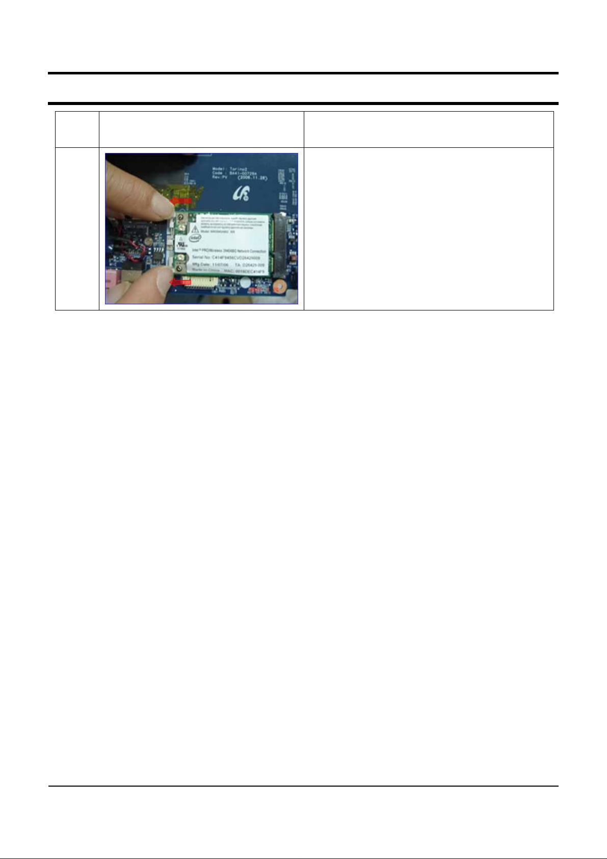
31. Separate Wireless LAN Module with pushing
side pin toward to red arrow direction like pic.
4-8
Page 9

- This document cannot be used without the authorization of Samsung -
4. Disassembly and Reassembly
Part
Name
Figure Description
1. 1st, Remove 4 Rubber-Front and 2nd,
Remove 4 screws.
- M2xL4 : 2 EA (Upper side, BLK)
(YELLOW)
-M2xL6:2EA(Lowerside,WHT)(RED)
*CAUTION:
Be careful with scratch in LCD-Front when
removing
Rubber-Front.
2. Separate lower side of LCD Front Putting in
hands between LCD Panel and LCD Front.
3. Separate left and right side with the same
way.
4. Separate upper side with the same way.
*CAUTION
Don’t get in too much force with
disassembling
LCD Front.
LCD
Ass'y
5. Remove 3 screws.
-M2xL4:3EA(RED)
6. Separate LCD Cable and invertor b'd
connector
like pic.
4-9
Page 10
- This document cannot be used without the authorization of Samsung -
4. Disassembly and Reassembly
Part
Name
Figure
Description
7. Disassemble Inverter B’d like pic.
(Must separate Inverter B’d and LCD Panel’s
cable first.)
8. Remove screws for hinges.
(Only 6 black color screws.)
- M2xL4 : 6 EA (YELLOW)
LCD
Ass'y
9. Disassemble Hinge L/R and LCD Panel.
10. Disassemble Bracket-Upper.
4-10
Page 11

- This document cannot be used without the authorization of Samsung-
4. Disassembly and Reassembly
Part
Name
LCD
Ass'y
Figure Description
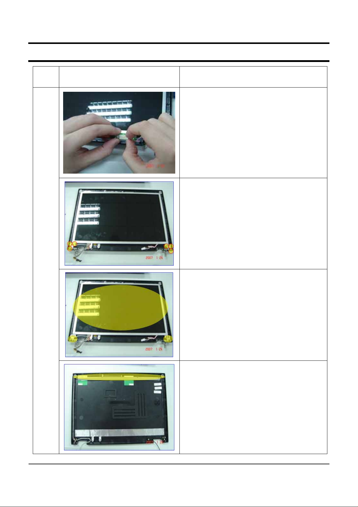
11. Disassemble Wireless Antenna.
(the same with right side)
11-1. In case of Camera, as the same method,
disassemble Camera Module and Cable all.
(For Camera Option)
12. Reverse LCD Panel, Remove tapes at point
of
no.1 and no.2.
13. Separate LCD Cable to pull toward to red
arrow
direction like pic.
4-11
Page 12

- This document cannot be used without the authorization of Samsung-
4. Disassembly and Reassembly
Part
Name
Figure Description
1. Remove screws for ONTOP B’D and
BRACKET TOUCHPAD.
- M2xL4 : 1 EA (YELLOW)
-M2xL3:2EA(RED)
2. Separate MIC.
TOP
Ass'y
3. Separate ONTOP B’D and Cable.
4. Separate Touchpad FFC.
4-12
Page 13

- This document cannot be used without the authorization of Samsung-
4. Disassembly and Reassembly
Part
Name
TOP
Ass'y
Figure Description
5. Disassemble BRACKET-TOUCHPAD.
6. Disassemble Touchpad-B’D.
7. THE END.
4-13
 Loading...