

Page 1

- This Document can not be used without Samsung's authorization -
4. Troubleshooting
1) General
(1) Tools used for repairing the product
System Diagnostics Disk
MS-DOS Booting Disk
System Diagnostics Card
Screwdrivers (┼,━)
Tweezers
Multi-meter
Oscilloscope
Logic Analyzer
(2) Replaceable Units (FRU: Field Replaceable Unit)
DDRII RAM Module
2.5" SATA HDD
ODD – Super multi Dual layer drive or DVD Combo Drive or Etc.
Wireless LAN Module
Bluetooth Module
MDC Module
Camera Modual
DMB Module(option)
Keyboard
System Fan
TouchPad
LCD Panel
LCD Inverter
Main Board
PCMCIA Frame
Harness Cable – MDC Cable, Bluetooth Cable, LCD Cable,Camera Cable and DMB Cable
2 Types of Wireless LAN Antenna
FFC – Touch Pad FFC and SATA FPC
5-1
Page 2
- This Document can not be used without Samsung's authorization -
4. Troubleshooting
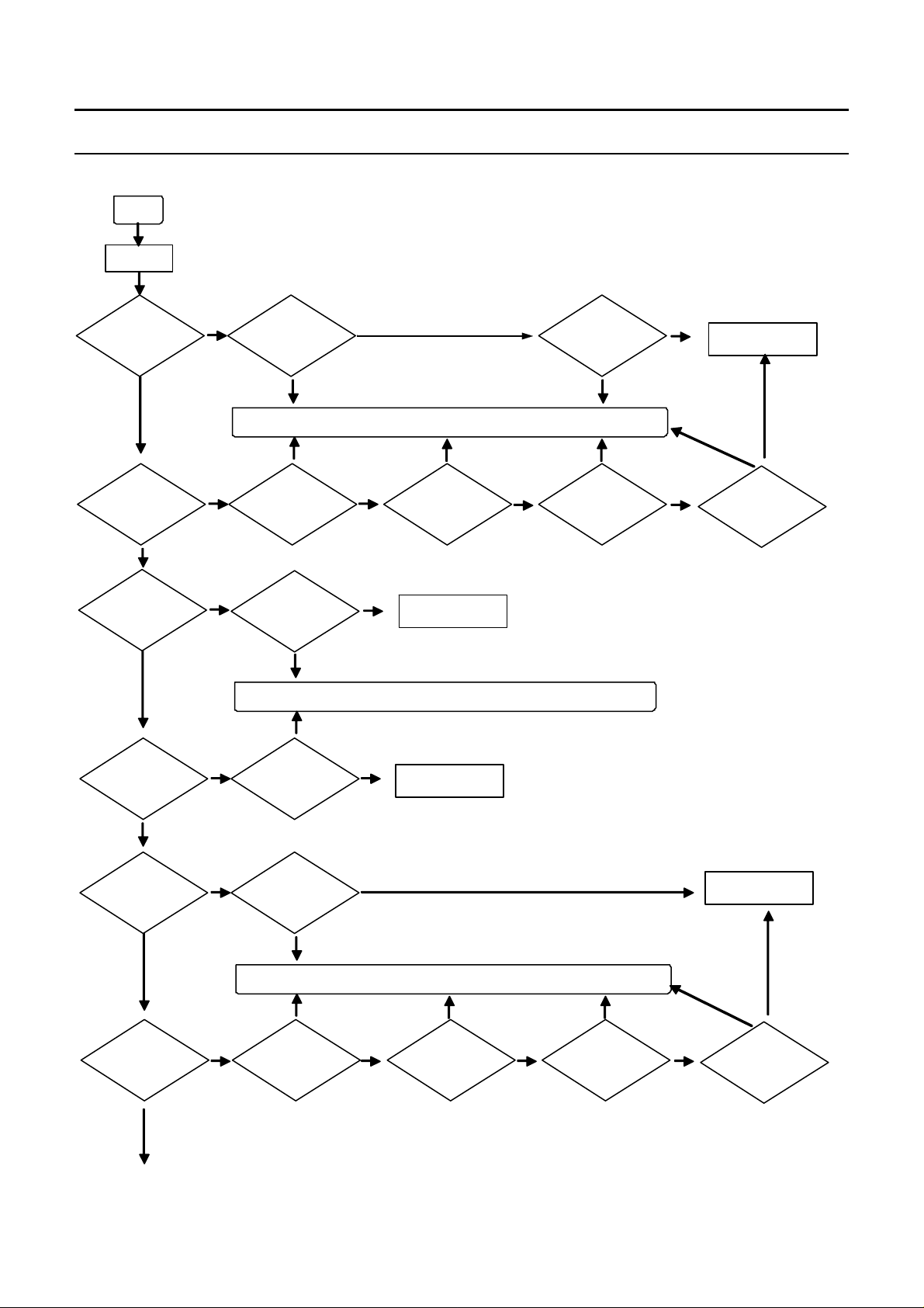
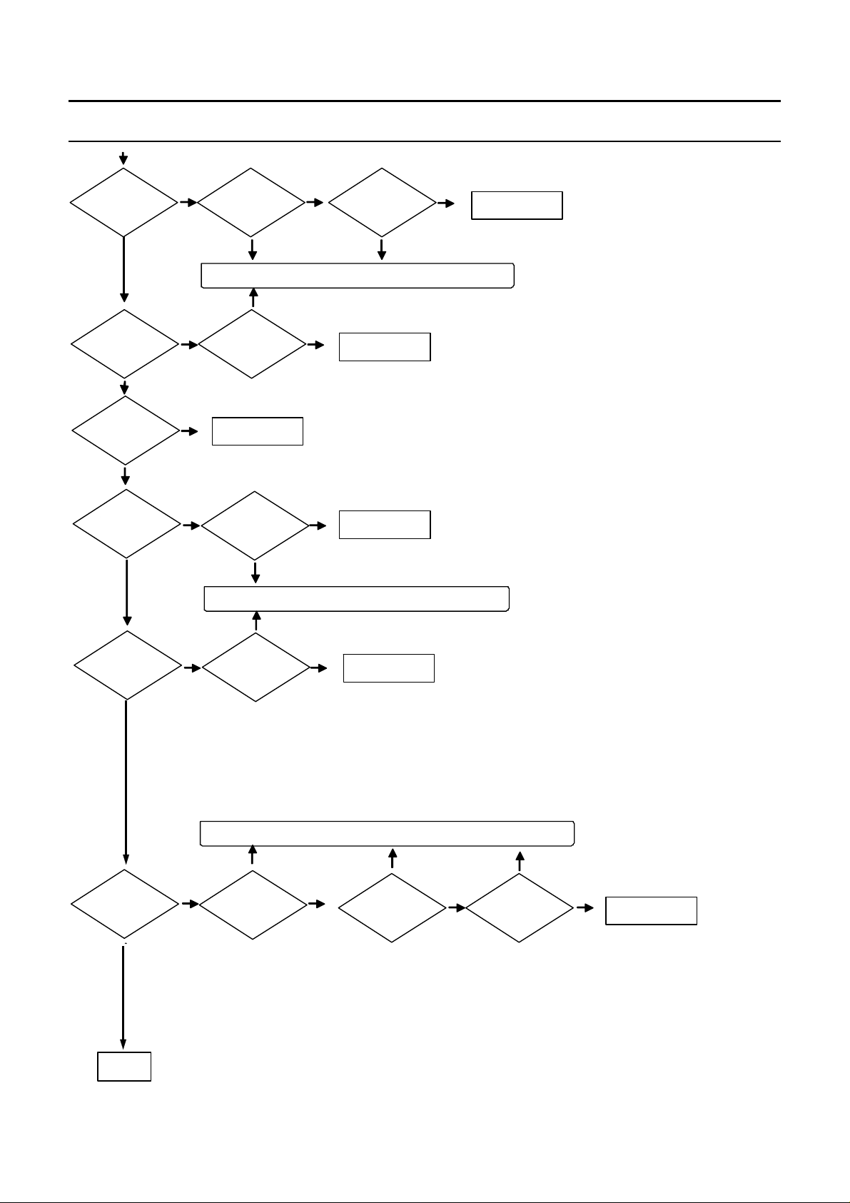
2) Debugging Flow Chart
Start
Power o n
?
Power on?
YES
?
L C D d isp la y is O K ?
YES
Keyboard function is OK ?
?
YES
HDD and ODD
?
recognition is OK
in C M O S ?
C hec k Ad ap ter an d
?
NO
C hec k R A M an d
?
NO
C he ck K eyb o ard
connection and
NO
C h e ck th e co n n ectio n
and change the unit.
No problem
Check Ontop board &
Battery.
It is
problem.
Solution : Replace the defected part or revise the connectivity..
It is
problem.
No problem
rep lace it.
No problem
?
rep lace it.
It is
problem.
Solution : Replace the defected part or revise the connectivity..
It is
problem.
No problem
?
?
cable
It is
problem.
It is
problem.
?
C hec k L C D cab le.
Change M ainboard
an d ch eck it.
Change M ainboard
an d ch eck it.
No problem
No problem
C h eck th ere is any
?
sh o rt in th e m ain
board.
It is
problem.
It is
problem.
C h eck L C D
?
Panel and
In v e rt er
No problem
It is
problem.
No problem
Change M ainboard
an d ch eck it.
No problem
?
C h eck N o rthb rid g e
YES
?
OS booting is OK?
YES
Touchpad
?
function is OK?
YES
NO
NO
?
O S is corru p ted ?
It is
problem.
Solution : Replace the defected part or revise the connectivity.
It is
problem.
Check Touchpad
?
FFC (M /B)
No problem
No problem
It is
problem.
Check Touchpad
?
FFC (module)
5-2
No problem
It is
problem.
Check Touchpad
?
In terface b o ard
It is
problem.
No problem
Change M ainboard
an d ch eck it.
No problem
Change
?
Touchpad, and
check function.
Page 3
- This Document can not be used without Samsung's authorization -
4. Troubleshooting
?
S pe aker's sou n d is O K ?
YES
Headphone,
?
SPD IF, M IC
f u n c t io n is O K ?
YES
?
U S B is O K ?
YES
6in1card
5in 1 card
?
function is ok?
f u n c t io n is O K ?
YES
LAN,MODEM ,
?
WLAN
function is
NO
NO
NO
NO
NO
N o problem
?
C h eck d riv er statu s.
It is
problem.
S o lu tio n : R ep lace th e d efected p art o r rev ise th e co n n ectiv ity.
It is
problem .
N o problem
?
C h eck d riv er statu s.
C h an g e M ain b oard
an d ch eck it.
?
C h eck d riv er statu s.
It is
problem .
S olutio n : R ep lace th e defected p art o r rev ise th e co n n ectiv ity.
It is
problem .
No problem
?
C h eck d riv er statu s.
C h eck sp eaker
?
co n n ectio n an d
sp eaker cable
It is
problem .
C hange M ainboard
an d ch eck it.
C hange M ainboard
an d ch eck it.
C hange M ainboard
an d ch eck it.
N o p r o b le m
C h an g e M ain bo ard
an d ch eck it.
YES
?
D M B function is ok?
YES
Bluetooth
?
function is OK?
YES
1394 fu n ctio n is
?
OK?
YES
End
NO
NO
NO
?
C h eck d riv er statu s.
It is
problem .
S o lu tio n : R ep lace th e d efected p art o r rev ise th e co n n ectiv ity.
It is
problem.
?
C h eck d riv er statu s
C hange M ainboard
an d ch eck it.
No problem
C h eck D M B
?
m o d u le is O K ?
It is
problem.
It is
problem.
?
C h eck B lu eto o th cab le.
5-3
N o problem
N o problemN o problem
C hange M ainboard
an d ch eck it.
It is
problem .
C heck
?
Bluetooth
module.
N o problem
C hange M ainboard
an d ch eck it.
Page 4

- This Document can not be used without Samsung's authorization -
4. Troubleshooting
3) System Diagnosis
(1) System Diagnostics Card
The Diagnostics Card shows the system operations during the POST (Power On Self Test) in a
2 digit hexadecimal number by connecting the cable to the 10 pin connector below the PCMCIA slot
after separating the Top part. The card is used to evaluate the reason for the malfunction without
disassembling the system when the system malfunctions and to test if the system operates normally
after replacing a defective FRU.
(2) Debugging Code
In general, if a defect of the circuit or part is detected during the system test, the system stops at
a particular code. The error codes for each part of the system are listed in the following table.
Code Beeps POST Routine Description
02h Verify Real Mode
03h Disable Non-Maskable Interrupt
04h Get CPU type
06h Initialize system hardware
08h Initialize chipset with initial POST values
09h Set IN POST flag
0Ah Initialize CPU registers
0Bh Enable CPU cache
0Ch Initialize caches to initial POST values
0Eh Initialize I/O component
0Fh Initialize the local bus IDE
10h Initialize Power Management
11h Load alternate registers with initial POST values
12h Restore CPU control word during warm boot
13h Initialize PCI Bus Mastering devices
14h Initialize keyboard controller
16h 1-2-2-3 BIOS ROM checksum
17h Initialize cache before memory auto size
18h 8254 timer initialization
1Ah 8237 DMA controller initialization
1Ch Reset Programmable Interrupt Controller
20h 1-3-1-1 Test DRAM refresh
22h 1-3-1-3 Test 8742 Keyboard Controlle
24h Set ES segment register to 4 GB
26h Enable A20 line
28h Auto size DRAM
29h Initialize POST Memory Manager
2Ah Clear 512 KB base RAM
2Ch 1-3-4-1 RAM failure on address line xxxx*
2Eh 1-3-4-3 RAM failure on data bits xxxx* of low byte of memory bus
2Fh Enable cache before system BIOS shadow
30h 1-4-1-1 RAM failure on data bits xxxx* of high byte of memory bus
32h Test the CPU bus-clock frequency
33h Initialize Phoenix Dispatch Manager
36h Warm start shutdown
5-4
Page 5

- This Document can not be used without Samsung's authorization -
4. Troubleshooting
38h Shadow system BIOS ROM
3Ah Auto size cache
3Ch Advanced configuration of chipset registers
3Dh Load alternate registers with CMOS values
42h Initialize interrupt vectors
45h POST device initialization
46h 2-1-2-3 Check the ROM copyright notice
48h Check the video configuration against CMOS
49h Initialize PCI bus and devices
4Ah Initialize all video adapters on the system
4Bh Quiet Boot start (optional)
4Ch Shadow video BIOS ROM
4Eh Display the BIOS copyright notice
50h Display the CPU type and speed
51h Initialize EISA board
52h Test the keyboard
54h Set key click if enabled
58h 2-2-3-1 Test for unexpected interrupts
59h Initialize POST display service
5Ah Display the prompt "Press F2 to enter SETUP"
5Bh Disable CPU cache
5Ch Test RAM between 512 and 640 KB
60h Test extended memory
62h Test extended memory address lines
64h Jump to UserPatch1
66h Configure advanced cache registers
67h Initialize Multi Processor APIC
68h Enable external and CPU caches
69h Setup System Management Mode (SMM) area
6Ah Display external L2 cache size
6Bh Load custom defaults (optional)
6Ch Display shadow-area message
6Eh Display possible high address for UMB recovery
70h Display error messages
72h Check for configuration errors
76h Check for keyboard errors
7Ch Set up hardware interrupt vectors
7Eh Initialize coprocessor if present
80h Disable onboard Super I/O ports and IRQs
81h Late POST device initialization
82h Detect and install external RS232 ports
83h Configure non-MCD IDE controllers
84h Detect and install external parallel ports
85h Initialize PC-compatible PnP ISA devices
86h Re-initialize onboard I/O ports.
87h Configure Mothe board Configurable Devices
88h Initialize BIOS Data Area
89h Enable Non-Maskable Interrupts (NMIs)
8Ah Initialize Extended BIOS Data Area
5-5
Page 6

- This Document can not be used without Samsung's authorization -
4. Troubleshooting
8Bh Test and initialize PS/2 mouse
8Ch Initialize floppy controller
8Fh Determine number of ATA drives (optional)
90h Initialize hard-disk controllers
91h Initialize local-bus hard-disk controllers
92h Jump to UserPatch2
93h Build MPTABLE for multi-processor boards
95h Install CD ROM for boot
96h Clear huge ES segment register
97h Fixup Multi Processor table
98h 1-2 Search for option ROMs. One long, two short beeps on
che checksum failure
99h Check for SMART Drive (optional)
9Ah Shadow option ROMs
9Ch Set up Power Management
9Dh Initialize security engine (optional)
9Eh Enable hardware interrupts
9Fh Determine number of ATA and SCSI drives
A0h Set time of day
A2h Check key lock
A4h Initialize Typematic rate
A8h Erase F2 prompt
AAh Scan for F2 key stroke
ACh Enter SETUP
AEh Clear Boot flag
B0h Check for errors
B2h POST done - prepare to boot operating system
B4h 1 One short beep before boot
B5h Terminate QuietBoot (optional)
B6h Check password (optional)
B9h Prepare Boot
BAh Initialize DMI parameters
BBh Initialize PnP Option ROMs
BCh Clear parity checkers
BDh Display Multi Boot menu
BEh Clear screen (optional)
BFh Check virus and backup reminders
C0h Try to boot with INT 19
C1h Initialize POST Error Manager (PEM)
C2h Initialize error logging
C3h Initialize error display function
C4h Initialize system error handler
C5h PnPnd dual CMOS (optional)
5-6
Page 7
- This Document can not be used without Samsung's authorization -
4. Troubleshooting
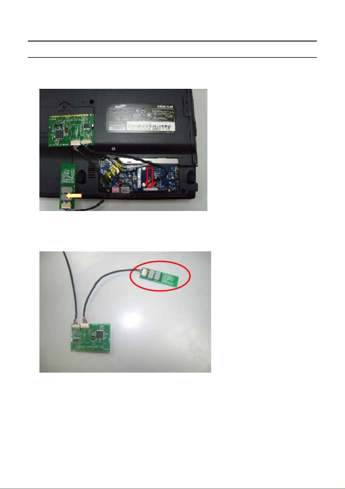
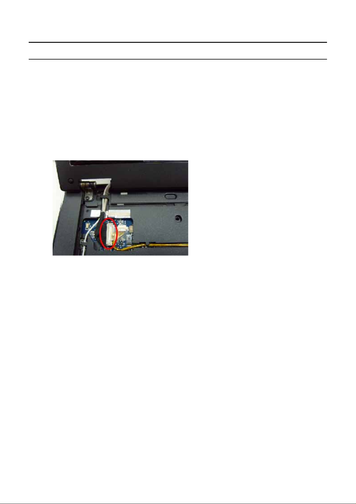
(3) Use of Debug card
-. Like upper picture, debug card is connected to DEBUG connector(as following) in Main board.
-. Debug code is shown at the viewer in red line.
5-7
Page 8
- This Document can not be used without Samsung's authorization -
4. Troubleshooting
4) Hardware Troubleshooting
For the procedures to disassemble each part, refer to the descriptions of Chapter 4, “Disassembly and
Reassembly”.
◆
LCD Related Troubles
1. The screen is dark or the colors of the screen are distorted.
→
Check the connection status between the LCD module and the LCD cable, between the LCD
cable and the main board LCD connector and between the LCD cable and the LCD inverter.
→
Replace the LCD cable or LCD inverter.
→
CheckifthereisapartoftheLCDthatisbentorbrokenduetoimpact.
2. No picture appears on the screen.
→
Check the connection status between the LCD module and the LCD cable, between the LCD
cable and the main board LCD connector and between the LCD cable and the LCD inverter.
→
Replace the LCD cable or LCD inverter.
→
Check if the System LED of the main board is blinking. (Check if it is operating or not)
→
Checkifthememorymoduleisoutoforder.
→
Check if the Power button can be normally pressed.
3. The LCD brightness is not adjusted.
→
Check if the LCD inverter is out of order.
→
Check the BIOS version and check if the standard adapter is used.
→
Replace the LCD cable or LCD inverter and check if it is out of order.
4. The LCD blinks while the system is in operation.
→
Check if there is a magnetic body near the touch pad button or the system or check if there is
an exterior defect to the LCD or system.
→
Replace the LCD cable or LCD inverter and check if it is out of order.
→
Check if a standard adapter is being used (R20/R21:19V/3.16A/60W).
5-8
Page 9
- This Document can not be used without Samsung's authorization -
4. Troubleshooting
◆
Main System Troubles
5. The system is not turned off.
→
Check if the AC adapter LED is lit and if the adapter is properly connected to the system.
(Check the adapter LED)
→
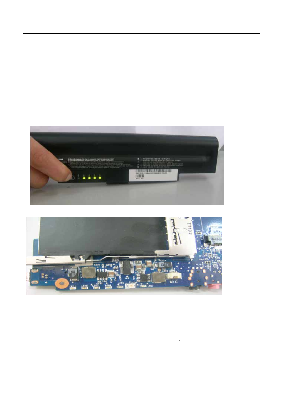
If the AC adapter is not connected, check the charge status of the battery. Even if the battery
is charged, if the remaining battery charge is too low, the system may not be turned on.
(As the following figure shows, press the PUSH button on the battery and check the remaining
battery charge via the LEDs)
→
Check if there are any alien substances in the Power switch. if have,change the LED
6. Although system power is supplied, the system does not boot or immediately turns off after being
turned on.
→
Since this may be a short circuit in the system, disconnect the power immediately, disassemble
the system and check if there are any conducting alien objects such as a screw inside.
→
Check the connection status between the CPU and the RHE.
→
Replace the memory module and check if it is out of order.
→
Reset the RTC Reset terminal next to the memory socket.
Remove RTC cabel from RTC connector
5-9
Page 10

- This Document can not be used without Samsung's authorization -
4. Troubleshooting
Connect the two pad of the cap for a while
→
Replace the main board.
7. The Express card is not inserted or the Eject button does not work.
→
This may occur when the insulator within the Express card slot is enwrapped.
→
Replace the Express card slot frame and check if it is out of order.
8. There is no sound from the speaker.
(Insert the figure of the audio jacks so that the reader can check via the figure.)
→
Check if the earphones or headphones are connected to the MIC jack of if there are any alien
substances in the jack.
→
Check if the sound is muted after booting up Windows.
→
Check the connection status of the speaker cable and check if the speaker is out of order.
→
Check if there is a magnetic object near the speaker.
5-10
Page 11

- This Document can not be used without Samsung's authorization -
4. Troubleshooting
9. I cannot hear sound through the headphones.
→
Check if the sound is muted in Windows.
→
Turnthevolumeup.
→
Replace the main board
10. The external microphone does not work normally.
→
Check the audio driver settings and change them if necessary.
Selecting the "1. Front panel microphone" option activates the external MIC.
→
Replace the main board
5-11
Page 12

- This Document can not be used without Samsung's authorization -
4. Troubleshooting
11. The HDD is not recognized.
→
Check the connection status of the HDD connector. fixup HDD, check whether the system can
be found. if not,change the connector on the motherboard and check again.
→
If the 'Operating system not found' message appears during the booting process even though
the HDD is recognized by CMOS, the operating system of the HDD may be corrupted or the
HDD is out of order. In this case, format the HDD and reinstall the operating system or replace
the HDD with a new one.
12. The Touch Pad does not work or is malfunctioning.
→
Check the connection status of the Touch Pad FFC.
→
Check the connection status of the Touch Pad module
→
If there is no problem with the connections, replace any suspicious parts and check if they are
outoforder.
13. The battery is not charged or the battery charge LED malfunctions.
→
Check the standard voltage of the adapter.
5-12
Page 13

- This Document can not be used without Samsung's authorization -
4. Troubleshooting
→
Check if the battery is defective.
→
Replace the main board.
14. The LAN function does not work.
→
Check if the LAN cable is properly connected.
→
Check if the LAN driver is properly installed.
→
If the driver is properly installed, check if the LAN cable jack is out of order.
→
Replace the main board
15. The USB function does not work.
→
Check if the USB jack is out of order.
→
Replace the main board
16. The wireless LAN does not work normally.
→
Check if the WLAN slide switch is in the ON position.
→
Check if the WLAN driver is properly installed.
→
Check if the wireless LAN antenna cable is properly connected.
→
Replace the main board
5-13
Page 14

- This Document can not be used without Samsung's authorization -
4. Troubleshooting
17. The Fan does not work normally
→
Check if the Thermal is locked tightly.
→
Check if the Fan cable is properly connected
FAN Control Table
Voltage Address
RPM Noise
(Volt) (Hexa)
OFF FF OFF 20dBA
(for CPU
temperature)
CPU
Sensor(on/o
ff)
(for GMCH
temperature)
GMCH
sensor(on/off)
3C 2300 rpm 25dBA 55/50 65/55
32 2750 rpm 28dBA 62/58 68/65
2C 3100 rpm 30dBA 70/65 70/68
27 3450 rpm 32dBA 80/75 75/70
24 3750 rpm 37dBA 85/80 80/75
◆
When booting up the computer
18. The "Invalid System Disk. Replace the Disk and then press any key" message appears.
→
This message may appear when the connected USB memory or CD media does not include
bootable data.
→
The "Reboot and Select the proper Boot device or Insert a bootable media in the selected Boot
device and press a key" message appears.
→
Check if the signal and power cables are properly connected to the hard disk drive.
5-14
Page 15

- This Document can not be used without Samsung's authorization -
4. Troubleshooting
→
Check if the hard disk drive is recognized in the BIOS SETUP.
→
The operating system on the hard disk drive is corrupted. Reinstall Windows.
19. The "To enter BIOS SETUP, press <F2>. To continue, press <F1>." message appears.
→
This may happen when the BIOS settings are different from the system environment. In this
case, setup the BIOS according to your system environment.
→
Press <F2> to enter the BIOS SETUP.
→
Check if the date and time are correct in the BIOS SETUP.
→
Save the settings and restart the system.
20. The 'CMOS Checksum error’ message appears.
→
This message may appear when the CMOS battery of the main board is completely discharged.
In this case, replace the battery with a new one of the same type and set up the BIOS SETUP
according to your system environment.
21. Windows boots up in safe mode.
→
This may happen when Windows was not shut down normally. Therefore, shut down the system
by selecting Start > Turn Off Computer.
→
This may happen when the system settings have been incompletely recognized.
→
Run Check Disk.
22. I cannot boot up the computer with a USB floppy drive or from USB memory.
→
Check if the diskette is bootable.
→
This may happen when the booting priority of the device is low. In this case, change the
booting priority in the BIOS SETUP.
◆
When shutting down the computer
23. The computer is not shut down
→
If Windows does not end normally, you can forcibly shut down the system by pressing the
Power button. If the power-saving feature is activated on the Power button, press the Power
button for more than 4 seconds to turn the computer off. If the computer is then turned on again,
Check Disk is automatically run.
◆
Windows / Screen Related Problems
24. The computer hangs while running a program.
→
If the running program causes an error:
In Windows XP, press the <Ctrl>, <Alt> and <Del> key combination, select the application
program and click on End Task in the Applications tab of the [Windows Task Manager] window.
In Windows 2000, press the <Ctrl>, <Alt> and <Del> key combination, select the application
programoranapplicationthatdoesnotrespondandclickonEndTaskinthe[EndProgram]
window.
5-15
Page 16

- This Document can not be used without Samsung's authorization -
4. Troubleshooting
→
If Windows does not respond, restart the computer. Restart the computer by pressing the Power
button.
25. No picture is displayed on the external monitor.
→
Press the Switch LCD/CRT Monitor function key and check if the screen output is output to
another display device.
→
Check if the hardware is out of order referring to the descriptions in the LCD related section of
the Hardware Troubleshooting.
→
For models with external graphics, replace the VGA board and check if it is out of order.
◆
CD/DVD-ROM Related Troubles
26. A disc is not recognized or read.
→
Check if the ODD module and the main board are properly connected with the 50 pin connector.
→
Replace the ODD, if necessary.
◆
Power-Saving Mode Related Troubles
27. Connecting a USB device to the computer in standby mode.
→
If a USB device is connected to the computer in standby mode, the screen may be abnormally
displayed.
You have to connect a USB device when the computer is operating normally.
28. A USB device is not working normally when the computer returns from standby mode.
→
In this case, separate and reconnect the USB device.
29. The picture is displayed abnormally when the computer running the Command Prompt (MS-DOS)
enters standby mode and then returns from standby mode.
→
Press the <Alt> and <Tab> key combination to display the picture on the screen.
5-16
Page 17

- This Document can not be used without Samsung's authorization -
4. Troubleshooting
5) Device Settings Related Software Diagnosis
(1) Check if the drivers of each of the devices are properly installed. That is, check if there are any
yellow exclamation marks in the Device Manager.
(2) Check the device driver version and check if it is conflicting with another driver. If the driver is
not properly installed, install a new driver.
(The following figure illustrates the properties of the Internal GFx device driver).
5-17
Page 18

- This Document can not be used without Samsung's authorization -
4. Troubleshooting
(3) Check if the program is properly installed.
Click on the Realtek Control Panel in the Control Panel and check if the function works normally.
5-18
Page 19

- This Document can not be used without Samsung's authorization -
4. Troubleshooting
(4) HDD and ODD Related Problems
For an HDD, check if the HDD operates in Ultra DMA Mode 5 by selecting the Primary IDE
Channel in the Control Panel as follows. If it does not, check the BIOS SETUP, reinstall the
operating system or replace the HDD-FPC or HDD, if necessary.
5-19
Page 20

- This Document can not be used without Samsung's authorization -
4. Troubleshooting
ForanODD,checkifitoperatesinUltraDMAMode2.Ifitdoesnot,checkifthediscinserted
into the ODD is clean. If the disc is contaminated, the access speed may slows down. If the disc is
clean, check the BIOS SETUP, reinstall the operating system or ODD, if necessary.
Check if the HDD and ODD models are properly displayed. If not, check the BIOS SETUP or
replace the FPC or drive, if necessary.
(5) Windows Vista System
The operating system(OS) installed on this product is the latest version of Windows Vista,
You cannot install an operating system other than vista as well as any unauthorized copy of
Windows Vista.
Other operating systems (Windows 98,Windows ME,Windows 2000,Windows XP,Windows 2003
Server,UNIX and LINUX.other Windows Vista versions,etc.)other than the operating system
already installed on this computer are not supported.
Installing a program that does not support Windows Vista,may cause the program to not work
properly.
In this case,ask the corresponding software manufacturer about the problem . if you request our
services to resolve a problem caused bu incompatible software.
5-20
Page 21

- This Document can not be used without Samsung's authorization -
4. Troubleshooting
(6) Other Problems
Press each corresponding button and check its operation.
The following figure illustrates the operation of the volume control button.
The drivers and application software are listed in the following table.
Drivers VistaHP(KOR)
Chipset Driver 8.1.1.1010
DMB USB Driver 5.0.9.3 Vista 32Bit (SABI Off, Logo)
Graphics Driver
Wireless LAN Driver(Intel) 11.1.0.86 32bit (PV)
Sound Driver 6.0.1.5378
Bluetooth Driver 6.0.1.3700
Touchpad Driver
Modem Driver 2.1.75_Vista_LogoedR
Memory Card Driver 6.0.1.10
7.14.10.1214
9.1.15.0
LAN Driver 9.12.3.3
5-21
Page 22

- This Document can not be used without Samsung's authorization -
4. Troubleshooting
Applications
ABBYY Lingvo 9(RUS)
Samsung Battery Manager 3.2.0.8
Easy Box
Magic Keyboard
Samsung Update Plus
Network Manager 3.0.1.7
Display Manager 2.1.2.0
HotStart Shell(AVSTation Now) 4.0.10.5
Magic Doctor 5.009
CyberLink DVD Solution 36 - Vista
nTracker(KOR) 3.0.1.0
Adobe Reader(RUS)
Adobe Reader 7.0.8.218
McAfee Anti-Virus 13.3.0.132
MS office 2007 ready(KOR/export) 1
Vista Manual Firenze-R(R55)
ㅤ
ㅤ
ㅤ
ㅤ
1.3.0.10
ㅤ
ㅤ
SW Media Installer -1of1(Vista) Vista 4.0.1.7
Vista-Hotfix-Bluetooth 1.0.0.1
Vista-Hotfix-common 1.0.0.3
Recovery Solution II 1.0.1.1
Media Center
Media Center Update(Vista) 2.0.3
Samsung Screen Saver(KOR)
SetDisplayResolution 1.2.0.0
Wallpaper 2.0.0.0
AVStation Movie Contents (KOR)
AVStation Movie Contents (NO KOR)
Play AVStation_PM_35_KM
Easy Partition Manager
Dungeon&Fighter Setup Icon 1.0.0.1_2
CSUP (MDA)
한글입력기
(KOR) 3.1.5
1.0.2.0
4.1.7
4.1.7
4.1.20.44
2.2.1.4
1.0.0.4
5-22
Page 23

- This Document can not be used without Samsung's authorization -
4. Troubleshooting
6) Battery Use Time
Check the following check lists for systems where the battery use time is too short to diagnose
problems.
(1) Check the battery
Check if the battery is out of order referring to the Battery check program distributed to Service
Centers and the 'Battery Check Manual' included in the 'Note-PC A/S Guide'.
1. Battery Check List
2. Criteria for each of the check lists.
5-23
Page 24

- This Document can not be used without Samsung's authorization -
4. Troubleshooting
5-24
Page 25

- This Document can not be used without Samsung's authorization -
4. Troubleshooting
5-25
Page 26

- This Document can not be used without Samsung's authorization -
4. Troubleshooting
3. Battery Capacity Table
4. Battery Check Program
5-26
Page 27

- This Document can not be used without Samsung's authorization -
4. Troubleshooting
(2) Check the battery use environment
1. Generally, the battery usage time in advertisements by notebook manufacturers refers to the
maximum battery use time. Since the system specifications and the usage environment may differ,
the user's battery usage time may differ from the advertisement even if there is no problem with
the system.
2. Conditions for the company's maximum battery use time
a. Minimum LCD brightness, base system, the wireless LAN R/F is turned off, BatteryManager-
Maximum Battery Mode
b. Measuring Tool: BatteryMark v.4.0.1
3. If a customer complains about the battery usage time, let them know that the battery usage time
may differ depending on the model specifications and the usage environment and recommend
the following usage environment for longer battery time.
a. Use the company's power-saving program, BatteryManager, and set BatteryManager to
Maximum Battery Mode.
b. LCD brightness: Set to the minimum level as long as the u ser does not experience
inconvenience.
c. Disable unnecessary devices
: Turn the wireless LAN R/F switch off and disable USB devices (DMB, fingerprint recognition
and Bluetooth)
5-27
Page 28

- This Document can not be used without Samsung's authorization -
4. Troubleshooting
7) Other
7)-1. CPU Spec
CPU 4-6 code Type 업체 P/N Description
T7700 0902-002199 uFCPGA LF80537GG0564M 2.4GHz,uFCPGA,479P,TR,PLASTIC,1.05V,34W,0to+100C,4MB,FSB800
T7500 0902-002198 uFCPGA LF80537GG0494M 2.2GHz,uFCPGA,479P,TR,PLASTIC,1.05V,34W,0to+100C,4MB,FSB800
T7300 0902-002197 uFCPGA LF80537GG0414M 2.0GHz,uFCPGA,479P,TR,PLASTIC,1.05V,34W,0to+100C,4MB,FSB800
T7100 0902-002196 uFCPGA LF80537GG0332M 1.8GHz,uFCPGA,479P,TR,PLASTIC,1.05V,34W,0to+100C,2MB,FSB800
Model Numbering Rule
7)-2.
5-28
 Loading...