

Samsung PV-MBA1BG 244, PV-MBA1BG 255, PV-MBA1CG 244, PV-MBA1CG 247, PV-MBA1CG 250 Installation Instructions Manual
...
PV module
Installation Instructions
Power to Imagine
• READ THIS INSTALLATION INSTRUCTION IN ITS ENTIRETY BEFORE INSTALLING, WIRING OR USING THIS
PRODUCT IN ANY WAY.
• LESEN SIE DIESE INSTALLATIONSANWEISUNG VOLLSTÄNDIG DURCH, EHE SIE DAS PRODUKT INSTALLIEREN,
ANSCHLIESSEN ODER SONST WIE VERWENDEN.
• SI RACCOMANDA DI LEGGERE COMPLETAMENTE QUESTE ISTRUZIONI PRIMA DI INSTALLARE, CABLARE O
UTILIZZARE IN QUALSIASI MODO IL PRODOTTO
• VEUILLEZ LIRE CES INSTRUCTIONS D’INSTALLATION DANS LEUR INTÉGRALITÉ AVANT L’INSTALLATION, LE
CÂBLAGE OU L’UTILISATION DE CE PRODUIT
• LEA ESTAS INSTRUCCIONES DE INSTALACIÓN EN SU TOTALIDAD ANTES DE INSTALAR, CABLEAR O USAR ESTE
PRODUCTO DE CUALQUIER FORMA
Jul. 2012
2_ introduction Rev. 12
introduction (english)
This manual contains important installation, maintenance and safety information. The word “module”
as used in this manual refers to one or more photovoltaic modules.
Please retain this manual for future reference.
IMPORTANT
!
Please read this document in its ENTIRETY before installing, wiring or using this product in any way.
Failure to comply with these instructions will invalidate the Samsung PV Modules Limited Warranty.
DISCLAIMER OF LIABILITY
Samsung accepts no liability for the usability and functionality of its solar modules if the instructions in this guide are not
followed. Since compliance with this guide and the conditions and methods of installation, operation, use and maintenance
of the modules are not checked or monitored by Samsung, Samsung accepts no liability for damage arising from improper
use or incorrect installation, operation, use or maintenance.
The information in this manual is believed to be reliable, but does not constitute an expressed and/or implied warranty.
As part of Samsung’s policy of continuous improvement, Samsung reserves the right to change product
specifications at any time without prior notice.
einleitung (deutsch)
Dieses Handbuch enthält wichtige Informationen für Installation, Wartung und Sicherheit. Der in
diesem Handbuch verwendete Begriff „Modul“ bezeichnet eines oder mehrere der Solarmodule.
Bewahren Sie diese Bedienungsanleitung zum späteren Nachschlagen auf.
WICHTIG
!
Lesen Sie diese Information VOLLSTÄNDIG, ehe Sie das Produkt installieren, anschließen oder sonst wie
verwenden.
Bei Nichtbeachtung dieser Anweisungen entfällt die Samsung-Garantie für die PV-Module.
HAFTUNGSAUSSCHLUSS
Samsung übernimmt keine Haftung für die Verwendbarkeit und Funktionstüchtigkeit ihrer Solarmodule, wenn die
Anweisungen in diesem Handbuch nicht befolgt wurden. Die Einhaltung dieses Handbuchs und der Bedingungen
und Methoden für Installation, Betrieb, Verwendung und Wartung der Module wird von Samsung weder geprüft noch
überwacht. Samsung übernimmt keine Haftung für Schäden, die sich aus unsachgemäßer Verwendung oder Fehlern bei
Installation, Betrieb, Verwendung oder Wartung ergeben.
Die Informationen in diesem Handbuch sind nach bestem Wissen richtig, daraus ist aber keine vertragliche oder
gesetzliche Garantie abzuleiten.
In Rahmen von Samsungs Politik ständiger Verbesserung behält sich das Unternehmen das Recht vor, die
technischen Daten des Produkts ohne vorherige Kündigung jederzeit zu ändern.
Rev. 12 introduction _3
introduzione (italiano)
Questo manuale contiene informazioni importanti sull’installazione, la manutenzione e la sicurezza. In
questo manuale, il termine “modulo” viene utilizzato con riferimento a uno o più moduli fotovoltaici.
Conservare questo manuale per futuri riferimenti.
IMPORTANTE
!
Leggere COMPLETAMENTE questo manuale prima di installare, cablare o utilizzare in qualsiasi modo il prodotto.
La mancata osservanza di queste istruzioni comporta l’annullamento della garanzia limitata di Samsung per
i moduli FV.
ESCLUSIONE DI RESPONSABILITÀ
In caso di mancata osservanza delle istruzioni fornite in questo manuale, Samsung declina ogni responsabilità in merito
all’idoneità all’uso e al funzionamento dei suoi moduli solari. Poiché la conformità con le istruzioni fornite in questa guida,
le condizioni e i metodi di installazione, di funzionamento, di utilizzo e di manutenzione dei moduli non vengono verificate
e monitorate da Samsung, Samsung declina ogni responsabilità per danni dovuti a uso improprio o errata installazione,
funzionamento, utilizzo o manutenzione del prodotto.
Le informazioni fornite in questo manuale sono ritenute affidabili, ma non costituiscono alcuna garanzia implicita e/o
esplicita.
In virtù della sua politica di costante miglioramento dei prodotti, Samsung si riserva il diritto di modificare le
specifiche del prodotto in qualsiasi momento senza preavviso.
introduction (français)
Le présent manuel comporte des informations importantes relatives à la sécurité, l’entretien et
l’installation du produit. Le mot « module » y est utilisé pour désigner un ou plusieurs modules
photovoltaïques.
Veuillez conserver ce manuel pour référence ultérieure.
IMPORTANT
!
Veuillez lire cette fiche dans son INTÉGRALITÉ avant l’installation, le câblage ou l’utilisation de ce produit.
Le non-respect de ces instructions annule la garantie limitée Samsung pour les modules photovoltaïques.
CLAUSE DE NON-RESPONSABILITÉ
En cas de non-respect des instructions du présent manuel, Samsung décline toute responsabilité quant au fonctionnement
des modules photovoltaïques. Les conditions et les méthodes d’installation, d’utilisation et d’entretien, tout comme le
respect des instructions du présent manuel ne sont pas contrôlés par Samsung. Les dommages dus à une utilisation non
conforme, ou à une installation ou un entretien incorrects n’engagent en aucun cas la responsabilité de Samsung.
Les informations du présent manuel sont fiables, mais ne constituent en aucun cas une garantie explicite et/ou implicite.
Dans le cadre de la politique d’amélioration continue de ses produits, Samsung se réserve le droit de modifier
les spécifications du produit sans préavis.

4_ introduction Rev. 12
introducción (español)
Este manual contiene información importante sobre la instalación, el mantenimiento y la seguridad. La
palabra “módulo” utilizada en este manual se refiere a uno o más módulos fotovoltaicos.
Conserve este manual para consultas futuras.
IMPORTANTE
Lea estas instrucciones EN SU TOTALIDAD antes de instalar, cablear o usar este producto de cualquier forma.
Si no se siguen estas instrucciones quedará invalidada la garantía limitada de Samsung de los módulos
fotovoltaicos.
DESCARGO DE RESPONSABILIDAD
Samsung no acepta ninguna responsabilidad por el uso y la funcionalidad de sus módulos solares, si no se siguen
las instrucciones de esta guía. Dado que Samsung no comprueba ni supervisa el cumplimiento de esta guía ni las
condiciones y métodos de instalación, funcionamiento, uso y mantenimiento de los módulos, Samsung no acepta ninguna
responsabilidad derivada de los daños por uso inapropiado, falta de seguimiento de las instrucciones de instalación ni por
un mantenimiento, uso o funcionamiento incorrectos.
La información de este manual se considera fiable, pero no conforma una garantía expresa ni implícita.
Conforme a la política de Samsung por una mejora continua, Samsung se reserva el derecho de cambiar las
especificaciones del producto en cualquier momento sin aviso previo.
Rev. 12 specifications _5
System integration parameters
Maximum system voltage (IEC) 1,000 VDC
Maximum system voltage (UL) 600 VDC
Maximum series fuse rating 15 A
Maximum reverse current 15 A
(Max 2 strings parallel without fuse)
Fire safety classification Class C
Certifications IEC 61215, IEC 61730,
UL 1703
Physical characteristics
Cells per module 60
Cell type Mono-crystalline silicon
Module
dimensions
1644x992x46mm ±1mm
(64.72x39.06x1.81inch ±0.04inch)
Module weight Screw frame: 20.2kg (44.5 lbs)
Junction box IP65
Frame Anodized aluminum
Front glass 3.2mm(0.13inches) Tempered glass
specifications
PV-MBA1BG / PV-MBA1CG xxx 244 247 250 255
Performance at Standard Test Conditions (STC) : Irradiance 1000W/m
2
, AM 1.5, and cell temperature 25°C
Maximum power P
max (Wp) 244 247 250 255
Maximum power voltage V
mp (V) 30.2 30.5 30.7 31.1
Maximum power current I
mp (A) 8.08 8.11 8.15 8.21
Open circuit voltage Voc (V) 37.3 37.6 37.8 38.1
Short circuit current I
sc (A) 8.60 8.64 8.68 8.75
Module efficiency 14.96% 15.15% 15.33% 15.64%
Temperature coefficients
NOCT 45 ± 2 °C
Temperature coefficient
Isc 0.034 %/K
Voc -0.325 %/K
Pmax -0.438 %/K
The rated power may only vary by 0/+2% and all other electrical parameters by ±3%
All data subject to change without prior notice.
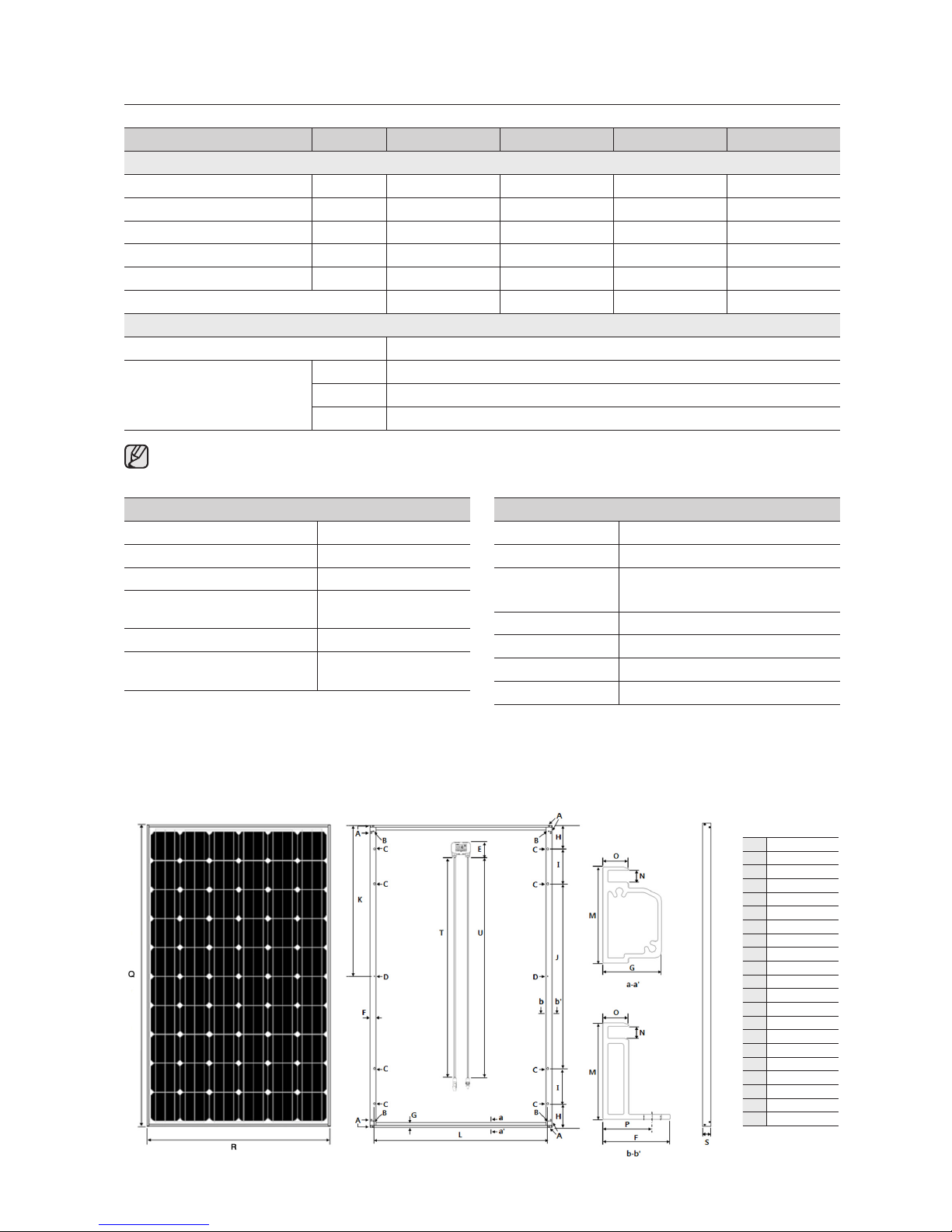
Figure 1 - Dimension of PV Module (PV-MBA1BG / PV-MBA1CG)
FRONT REAR SIDE
PV-MBA1BG
PV-MBA1CG
A 4.5x10 mm
B ø 6 mm
C ø 8.5x11 mm
D ø 4 mm
E 87.5 mm
F 32 mm
G 28 mm
H 130 mm
I 190 mm
J 1004 mm
K 822 mm
L 945 mm
M 46 mm
N 5.7 mm
O 12 mm
P 23.5 mm
Q 1644 mm
R 992 mm
S 46 mm
T 1000 mm
U 1000 mm
Ground Ground
6_ specifications Rev. 12
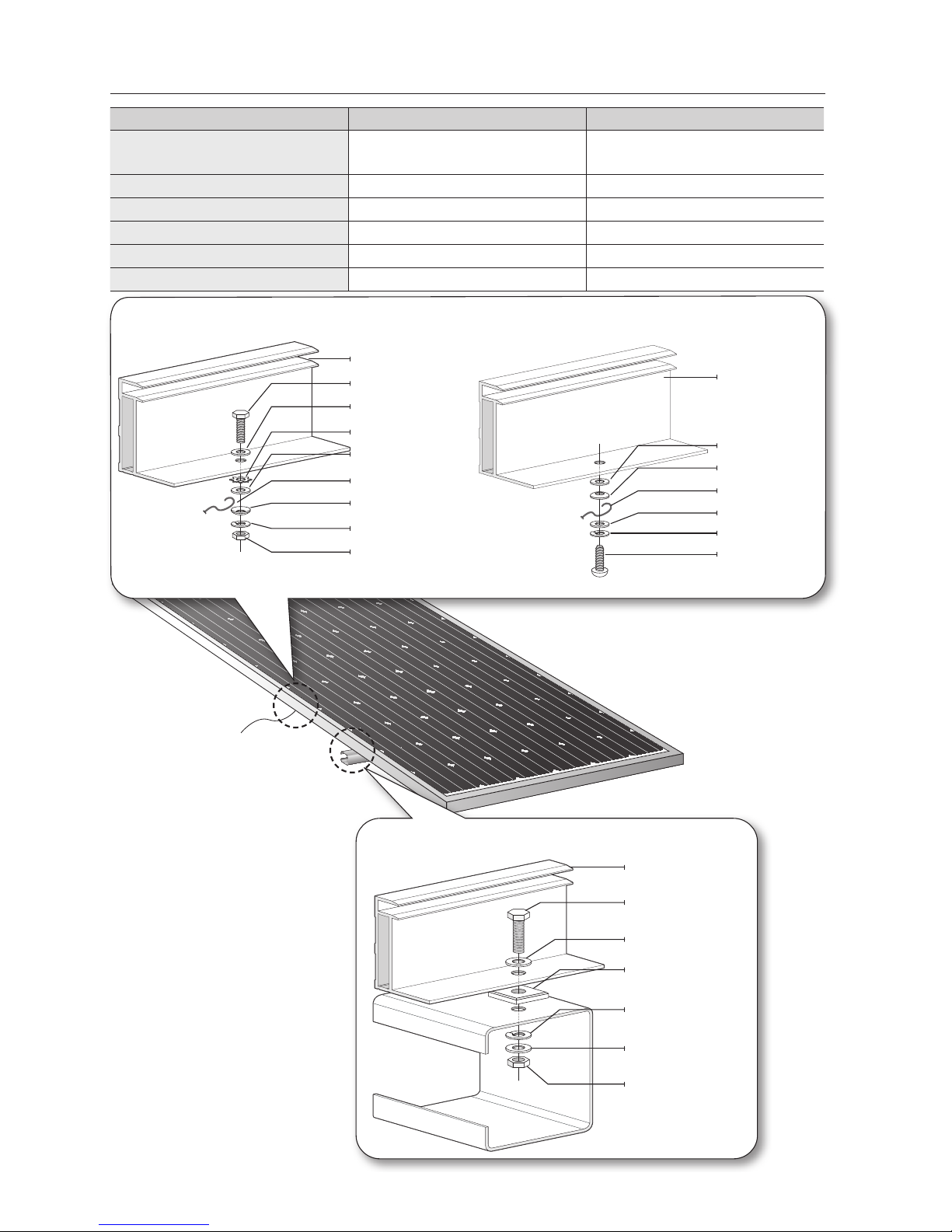
GROUNDING HARDWARE
Grounding hardware Dimension & material Remarks
Hexagon bolt & nut
or Self-tapping screw
M4, Stainless steel
#10-32, Stainless steel
Length of bolt: 20 mm
Flat washer M4, Stainless steel -
Flexible washer M4, Stainless steel -
Star washer M4, Stainless steel Cup washer M4, Stainless steel Ground wire #12, Copper wire -
Figure 2 - Grounding method 1
using bolt and nuts
Figure 2 - Grounding method 2
using self-tapping screw
Bolt
Module frame
Flat washer
Flat washer
Star washer
Grounding wire
Cup washer
Flexible washer
Nut
Figure 3 - Module mounting method
Bolt
Flat washer (M8)
Flexible washer (M8)
Nut
Gasket
Flat washer (M8)
Module frame
Module frame
Flat washer
Flat washer
Flexible washer
Self-tapping
screw
Grounding wire
Cup washer
Rev. 12 specifications _7
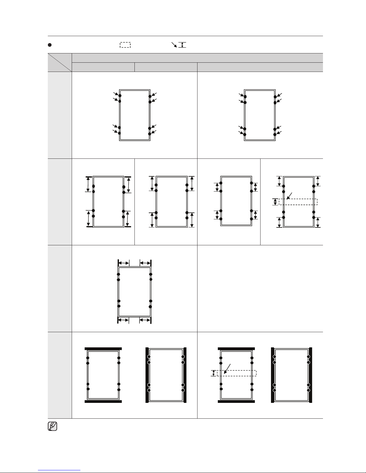
MOUNTING GUIDELINE (PV-MBA1BG/PV-MBA1CGxxx)
Frame mounting holes
Strut bar Permissible zone
Pressure burden assumptions
≤ 2,400 Pa ≤ 3,600 Pa ≤ 5,400 Pa
Screw Fitting
Clamping System
(Attachment to the
long module sides)
1/4 L
1/4 L
1/5 L
1/5 L
1/12~
1/6 L
1/12~
1/6 L
1/12L
1/12L
200mm
Center
strut bar
Clamping System
(Attachment to the
short module sides)
1/4 L 1/4 L
-
Insertion System
(Attachment to the
short module side)
200mm
Center
strut bar
Insertion system (attachment to the long module side) is permitted ≤5,400 Pa without a center strut bar.

8_ contents Rev. 12
contents
ENGLISH
9
9 GENERAL SAFETY INFORMATION
10 UNPACKING AND STORING MODULES
10 INSTALLATION
11 WIRING
12 MAINTENANCE
12 DISPOSAL CONSIDERATIONS
DEUTSCH
13
13 ALLGEMEINE SICHERHEITSHINWEISE
14 AUSPACKEN UND LAGERN DER MODULE
14 INSTALLATION
15 ELEKTROANSCHLUSS
16 WARTUNG
16 HINWEISE ZUR ENTSORGUNG
ITALIANO
17
17 INFORMAZIONI GENERALI SULLA SICUREZZA
18 DISIMBALLAGGIO E STOCCAGGIO DEI MODULI
18 INSTALLAZIONE
19 CABLAGGIO
20 MANUTENZIONE
20 SMALTIMENTO
FRANçAIS
21
21 INFORMATIONS GÉNÉRALES RELATIVES À LA
SÉCURITÉ
22 DÉSEMBALLAGE ET ENTREPOSAGE DES
MODULES
22 INSTALLATION
23 CÂBLAGE
24 ENTRETIEN
24 MISE AU REBUT
ESPAñOL
25
25 INFORMACIÓN GENERAL DE SEGURIDAD
26 DESEMBALAJE Y ALMACENAMIENTO DE LOS
MÓDULOS
26 INSTALACIÓN
27 CABLEADO
28 MANTENIMIENTO
28 OBSERVACIONES SOBRE LA ELIMINACIÓN
Rev. 12 English _9
ENGLISH
general safety information
All safety instructions in this document should be read and understood before installing this device.
Before installing modules, contact the appropriate
authorities to determine permissions, installation and
inspection requirements, which should be followed. Refer
to applicable regional and local codes.
WARNING!
Module interconnection cables pass direct current
(DC) and are sources of voltage when the module is
under load and when it is exposed to light.
Direct current can arc across gaps and may
cause injury or death if improper connection or
disconnection is made, or if contact is made with
modules that are frayed or torn. Do not connect or
disconnect modules when current from the modules
or an external source is present.
Installation should be performed only by
authorized personnel.
Installing a PV system requires specialized knowledge,
especially the installation and wiring of the PV modules.
This work should only be carried out by qualified and
authorized persons.
TO AVOID THE HAZARD OF
ELECTRIC SPARKS, SHOCK, FIRE,
BURNS, DAMAGE AND INJURY;
• Children and animals should not be allowed near the
installation while work is being carried out.
• Avoid electrical discharges when installing, cabling,
starting-up, or performing maintenance on the module.
• A module generates electricity when it is exposed to
sunlight or to other sources of light. Completely cover
surface of the module with an opaque material before
making or breaking electrical connections.
• Do not install or handle the modules or tools when they
are wet or during periods of high wind.
• Do not install the module where there are gases or
flammable vapors, as they can create sparks.
• Remove all metallic jewelry prior to installing this
product to reduce the chance of accidental exposure
to live circuits.
• Wear suitable clothing, guards, and gloves to prevent
you from direct contact with 30 VDC or greater.
• Use insulated tools to reduce your risk of electric
shock.
• There are no user serviceable parts within the module.
Do not attempt to repair any part of the module.
• Do not stand on, drop, scratch, or allow object to fall
on modules.
• If the front glass is broken, or the back sheet is torn,
contact with any module surface or module frame can
cause electric shock. Do not puncture, cut, scratch
or damage the glass or back sheet of a module. Back
sheet damage will void a module’s Limited Warranty
and may cause fire. Never use modules with a
damaged back sheet.
• Broken junction-boxes and/or broken connectors are
electrical hazards as well as laceration hazards. The
dealer or installers should remove the module from the
array and contact the supplier for disposal instructions.
• Never rest or leave a module unsupported or
unsecured.
• Do not artificially concentrate sunlight on a module.
• Do not touch the junction box terminals.
• Do not change the wiring of bypass diodes.
• If batteries are used with the module, follow
all recommendations indicated by the battery
manufacturer for safety.
• Completely ground all modules.
• When installing on a roof, ensure that the module is
attached with mechanical fastening. The roof should
have an adequate level of fire-resistance for the
application.
• CNL model installation shall be in accordance with
CSA C22.1, Safety Standard for Electrical Installations,
Canadian Electrical Code, Part 1.
• Mechanical loading test passed IEC 5400Pa (2400Pa
by UL).
• Contact your module supplier if maintenance is
necessary.
CAUTIONS!
Use a module for its intended purpose only.
Do not treat the back sheet, frame, or front
surface with paint or adhesives, to avoid
reducing its functionality, damage and causing
inoperable conditions, and other unknown
troubles.

10_ English Rev. 12
unpacking and storing modules
GENERAL
Warnings and instructions on the packaging should be observed. A record of the module serial numbers should be made
before installation and this should be noted the system documentation. Samsung modules are sent in boxes that are
specially designed to provide proper protection during shipping. It is advised to not remove the modules from the boxes
until installation. If it is necessary to put the modules into temporary storage, they should be kept in dry and properly
ventilated room. The solar modules must be installed and operated according to the latest available procedures.
Modules should be handled with care
The following points need to be observed when the modules are being unpacked, transported or stored:
• Wear non-slip gloves and carry a module by its frame with two or more people.
• Modules should be carried using both hands; the junction box should NOT be used as a grip.
• Modules should not be allowed to sag or bow under their own weight when being carried.
• Modules should not be subjected to loads/stresses and should not be stepped on or dropped.
• All electrical contacts should be kept clean and dry.
installation
MECHANICAL INSTALLATION
• Modules must be securely fastened using support
frames or mounting kit specialized for PV applications.
• Modules should be fixed in place in a manner suitable
to withstand all expected loads, including wind and
snow loads.
• Install modules where they are not shaded by
obstacles like buildings and trees. Especially pay
attention to avoid partially shading the modules by
objects during the daytime.
• Care must be taken to avoid low tilt angles which may
cause dirt to build-up on the glass against the frame
edge.
• Clearance between the roof surface and module frame
is required to allow cooling air to circulate around the
back of the module. This also allows any condensation
or moisture to dissipate. Install modules so that air can
circulate between the roof and the module. (60 mm:
2.36 inch gap minimum)
• In order to prevent water from entering the junction
box, which could present a safety hazard, modules
should not be mounted such that the front glass faces
downward (e.g. on a tracking structure that positions
the modules with the junction box facing skyward
during sleep mode).
• Great care should be exercised to ensure that
corrosion caused by the grounding means be avoided.
• Metals used in locations that are exposed to moisture
shall not be employed alone or in combinations that
could result in deterioration or corrosion. Thus, all
fasteners (nuts, bolts, washers, screws, etc.) must be
stainless steel unless otherwise specified.
• Refer to the applicable regional and local codes on
grounding PV arrays and mounting frames for specific
requirements (e.g. lightning protection). In the US the
array frame shall be grounded in accordance with NEC
Article 250.
• Recommendation of the gap between modules is
10 mm or more.
• Length of self-tapping screw or bolt should not be
more than 0.78’’ (20 mm) in order to avoid contacting
the backsheet of the module.
• Recommendation of bolt or screw torque range
: 1.6 N.m to 2.0 N.m.
• Contact an Authorized Representative with questions
regarding mounting profiles for modules if needed.
GROUNDING
• Attach an equipment ground conductor with stainless
steel hardware at one of the two designated Ø4
groundings holes on the module frame. Please refer to
national regulation or NEC Article 690 on grounding PV
arrays for special requirements.
• Modules can be grounded using third-party grounding
washer or clip systems provided they have been
tested and certified to local regulation on anodized
aluminum frame and are installed according to the
manufacturer’s specified instructions.
• If the grounding method above is adopted, please
choose one of the two grounding holes (Figure 2) and
use the grounding hardware with appropriate tools
such as a wrench, clips or others to ground the wires
in accordance with the requirements imposed by the
above hardware.
MOUNTING
• Always follow the mounting equipment vendors’
installation instructions in addition to these instructions.
In cases where the vendors’ instructions are more
stringent than those of Samsung, the vendors’
instruction shall apply.
 Loading...