

Samsung PS51F8500SLXXH Schematic

PlasmaTV
ChassisF5PA
ModelCodePS51F8500SLXXH
MANUAL
SERVICE
PlasmaTV
1.Precaution
2.ProductSpecication
3.DisassemblyandReassembly
4.Troubleshooting
5.WiringDiagram
PS51F8500SL
Contents
RefertotheservicemanualintheGSPN(seetherearcover)formoreinformation.

Contents
Contents
1.Precaution........................................................................................................................................1−1
1.1.SafetyPrecautions...................................................................................................................1−1
1.2.ServicingPrecautions...............................................................................................................1−3
1.3.StaticElectricityPrecautions......................................................................................................1−4
1.4.InstallationPrecautions.............................................................................................................1−5
2.ProductSpecication.........................................................................................................................2−1
2.1.ModelComparison...................................................................................................................2−1
2.2.Feature&Specications...........................................................................................................2−2
2.3.SpecicationsAnalysis.............................................................................................................2−4
2.4.DetailFactoryOption...............................................................................................................2−5
2.5.Accessories............................................................................................................................2−6
2.5.1.SuppliedAccessories...................................................................................................2−6
3.DisassemblyandReassembly..............................................................................................................3−1
3.1.OverallDisassemblyandReassembly..........................................................................................3−1
3.1.1.SeparationofSTANDP-BASE......................................................................................3−1
3.1.2.SeparationofASSYCOVERP-REAR............................................................................3−2
3.1.3.SeparationofASSYMAINBOARD...............................................................................3−3
3.1.4.SeparationofSMPS.....................................................................................................3−5
3.1.5.SeparationofSPEAKER...............................................................................................3−6
3.1.6.SeparationofMolPCamera...........................................................................................3−6
3.1.7.SeparationofFunction/Blutetoothmodule/WIFImodule.....................................................3−7
3.1.8.SeparationofBracketW all/Bracketmodule......................................................................3−8
4.Troubleshooting................................................................................................................................4−1
4.1.FirstChecklistforTroubleshooting.............................................................................................4−1
4.1.1.CheckpointsbyErrorMode...........................................................................................4−2
4.1.2.OperatingLogicLED...................................................................................................4−8
4.1.3.Blue-toothPairing.......................................................................................................4−10
4.2.FactoryModeAdjustments........................................................................................................4−11
4.2.1.EnteringFactoryMode.................................................................................................4−11
4.2.2.FactoryData...............................................................................................................4−13
4.3.ServiceAdjustment..................................................................................................................4−29
4.4.SoftwareUpgrade....................................................................................................................4−32
4.5.RS-232C................................................................................................................................4−34
4.6.A Vcontrolcode.......................................................................................................................4−35
5.WiringDiagram................................................................................................................................5−1
5.1.OverallWiring........................................................................................................................5−1
5.1.1.PinConnection...........................................................................................................5−3
5.1.2.ConnectorFunctions....................................................................................................5−8
iCopyright©1995-2013SAMSUNG.Allrightsreserved.

Contents
5.1.3.Cables.......................................................................................................................5−9
Copyright©1995-2013SAMSUNG.Allrightsreserved.ii
1.Precaution
DEVICE
UNDER
TEST
LEAKAGE
CURREN T
TESTER
TES T ALL
EXPOSED ME TAL
SUR FACES
2-WIRE CORD
ALSO TES T WITH
PLUG REVERSED
(US ING AC
ADAPTER PLUG
AS REQU IRED)
EARTH
GR OUND
( R E A D I N G
SHOULD NOT BE
ABOVE 0.5mA)
1.Precaution
Toavoidpossibledamage,electricshocksorexposuretoradiation,followtheinstructionsbelowwithregardtosafety,
installation,serviceandESD.
1.1.SafetyPrecautions
1)Makesureallprotectivedevicesareproperlyinstalledincludingnon-metallichandlesandcompartmentcoverswhen
installingorre-installingthechassisorchassisassemblies.
2)Makesurethatnogapsexistbetweenthecabinetsforchildrentoinserttheirngersintopreventchildrenfrom
receivingelectricshocks.GapsmentionedaboveincludeventilationholesofatoogreatmagnitudebetweenthePDP
moduleandthecabinetmask,andtheimproperinstallationoftherearcabinet.
Errorsmayoccurwhentheresistanceisbelow1.0MΩorover5.2MΩ.Inthesecases,makesurethatthedeviceis
repairedbeforesendingitbacktothecustomer.
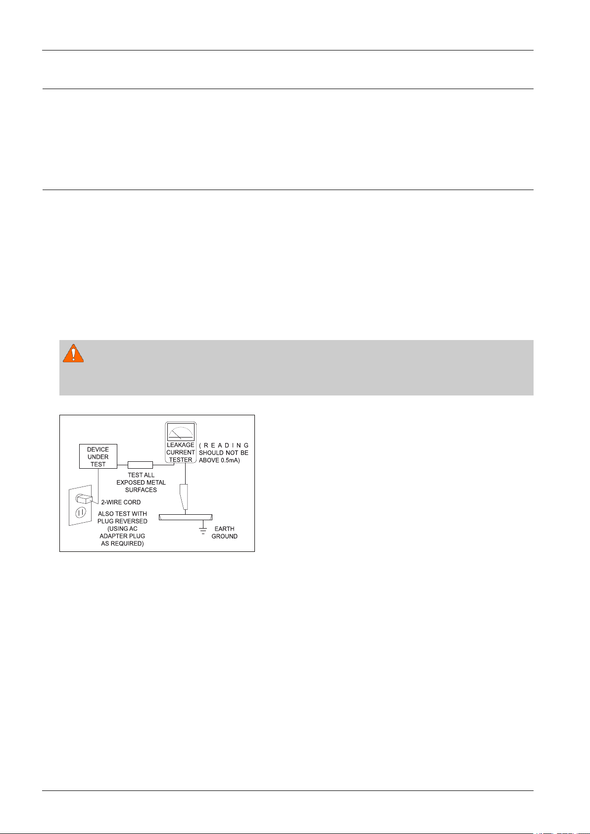
3)CheckforElectricityLeakage(ACLeakageT est)
WARNING
Donotuseaninsulatedtransformerforcheckingtheleakage.Useonlythosecurrentleakagetestersormirroring
systemsthatcomplywithANSIC101.1andtheUnderwriterLaboratory’sspecications(UL1410,59.7).
Figure1.1ACLeakageT est
4)Ahighvoltageismaintainedwithinthespeciedlimitsusingsafetyparts,calibrationandtolerances.Whenvoltage
exceedsthespeciedlimits,checkeachspecialpart.
5)W arningforEngineeringChanges:
Nevermakeanychangesoradditionstothecircuitdesignortheinternalpartforthisproduct.
Ex:Donotaddanyaudioorvideoaccessoryconnectors.Thismightcausephysicaldamage.
Furthermore,anychangesoradditionstotheoriginaldesign/engineeringwillinvalidatethewarranty.
6)W arning-HotChassis:
SomeTVchassisaredirectlyconnectedtooneendoftheACpowercordforelectricalreasons.Withoutinsulated
transformers,theproductcanonlyberepairedsafelywhenthechassisisconnectedtotheearthedendoftheAC
powersource.
TomakesuretheACpowercordisproperlyconnected,followtheinstructionsbelow.Usethevoltmetertomeasurethe
voltagebetweenthechassisandtheearthedground.Ifthemeasurementisover1.0V ,unplugtheACpowercordand
changethepolaritybeforereinsertingit.Measurethevoltagebetweenthechassisandthegroundagain.
1-1Copyright©1995-2013SAMSUNG.Allrightsreserved.

1.Precaution
7)SomeTVchassisareshippedwithanadditionalsecondarygroundingsystem.Thesecondarysystemisadjacentto
theACpowerline.Thesetwogroundingsystemsareseparatedinthecircuitusinganunbreakable/unchangeable
insulationmaterial.
8)Whenanyparts,materialorwiringappearoverheatedordamaged,replacethemwithnewregularonesimmediately.
Whenanydamageoroverheatingisdetected,correctthisimmediatelyandmakearegularcheckofpossibleerrors.
9)Checkfortheoriginalshapeofthelead,especiallythatoftheantennawiring,anysharpedges,theACpowerandthe
highvoltagepower.Carefullycheckifthewiringistootight,incorrectlyplacedorloose.Neverchangethespace
betweenthepartandtheprintedcircuitboard.ChecktheACpowercordforpossibledamages.Keepthepartorthe
leadawayfromanyheat-emittingmaterials.
10)SafetyIndication:
Someelectricalcircuitsordevicerelatedmaterialsrequirespecialattentiontotheirsafetyfeatures,whichcannotbe
viewedbythenakedeye.Ifanoriginalpartisreplacedwithanotherirregularone,thesafetyorprotectivefeatureswill
belostevenifthenewonehasahighervoltageormorewatts.
Criticalsafetypartsshouldbebracketedwith(
,).Useonlyregularpartsforreplacements(inparticular,ame
resistanceanddielectricstrengthspecications).Irregularpartsormaterialsmaycauseelectricshockorre.
Copyright©1995-2013SAMSUNG.Allrightsreserved.1-2

1.Precaution
1.2.ServicingPrecautions
WARNING
1)Firstcarefullyreadthe“SafetyInstruction”inthisservicemanual.
Whenthereisaconictbetweentheserviceandthesafetyinstructions,followthesafetyinstructionatalltimes.
2)Anyelectrolyticcapacitorwiththewrongpolaritywillexplode.
1)Theserviceinstructionsareprintedonthecabinet,andshouldbefollowedbyanyservicepersonnel.
2)MakesuretounplugtheACpowercordfromthepowersourcebeforestartinganyrepairs.
a)Removeorre-installpartsorassemblies.
b)Disconnecttheelectricplugorconnector,ifany .
c)Connectthetestpartinparallelwiththeelectrolyticcapacitor.
3)Somepartsareplacedatahigherpositionthantheprintedboard.Insulatedtubesortapesareusedforthispurpose.
Theinternalwiringisclampedusingbucklestoavoidcontactwithheatemittingparts.Thesepartsareinstalledback
totheiroriginalposition.
4)Aftertherepair,makesuretocheckifthescrews,partsorcablesareproperlyinstalled.Makesurenodamageiscaused
totherepairedpartanditssurroundings.
5)CheckforinsulationbetweenthebladeoftheACplugandthatofanyconductivematerials(i.e.themetalpanel,
inputterminal,earphonejack,etc).
6)InsulationCheckProcess:
UnplugthepowercordfromtheACsourceandturntheswitchon.Connecttheinsulatingresistancemeter(500V)to
theACplugblade.TheinsulatingresistancebetweenthebladeoftheACplugandthatoftheconductivematerial
shouldbemorethan1MΩ.
7)AnyB+interlockshouldnotbedamaged.
Ifthemetalheatsinkisnotproperlyinstalled,noconnectiontotheACpowershouldbemade.
8)Makesurethegroundingleadofthetesterisconnectedtothechassisgroundbeforeconnectingtothepositivelead.
Thegroundleadofthetestershouldberemovedlast.
9)Bewareofrisksofanycurrentleakagecomingintocontactwiththehigh-capacitycapacitor.
10)Thesharpedgesofthemetalmaterialmaycausephysicaldamage,soprotectyourselfbywearingglovesduringthe
repair.
11)Duetothenatureofplasmadisplaypanels,partialafter-imagesmayappearifastillpictureisdisplayedonthescreen
foralongperiodoftime.
Thisiscausedbybrightnessdeteriorationduetothestorageeffectofthepanel,andtopreventthisfromhappening,we
recommendthatthebrightnessandcontrastarereduced.(e.g.)Contrast:25,Brightness:50
1-3Copyright©1995-2013SAMSUNG.Allrightsreserved.

1.Precaution
1.3.StaticElectricityPrecautions
1)Somesemi-conductive(“solidstate”)devicesarevulnerabletostaticelectricity .ThesedevicesareknownasESD.
ESDincludestheintegratedcircuitandtheeldeffecttransistor.Toavoidanymaterialsdamagefromelectrostatic
shock,followtheinstructionsdescribedbelow.
2)Removeanystaticelectricityfromyourbodybyconnectingtheearthgroundbeforehandlinganysemi-conductiveparts
orassemblies.Alternatively ,wearadischargeablewrist-belt.
(Makesuretoremoveanystaticelectricitybeforeconnectingthepowersource-thisisasafetyinstructionfor
avoidingelectricshock)
3)RemovetheESDassemblyandplaceitonaconductivesurfacesuchasaluminumfoiltopreventaccumulatingstatic
electricity.
4)DonotuseanyFreon-basedchemicals.SuchchemicalswillgeneratestaticelectricitythatcausesdamagetotheESD.
5)Useonlygrounded-tipironsforsolderingpurposes.
6)Useonlyanti-staticsolderremovaldevices.
Mostsolderremovaldevicesdonotsupportananti-staticfeature.Asolderremovaldevicewithoutananti-staticfeature
canstoreenoughstaticelectricitytocausedamagetotheESD.
7)DonotremovetheESDfromtheprotectiveboxuntilthereplacementisready.MostESDreplacementsarecoveredwith
lead,whichwillcauseashorttotheentireunitduetotheconductivefoam,aluminumfoilorotherconductivematerials.
8)RemovetheprotectivematerialfromtheESDreplacementleadimmediatelyafterconnectingittothechassisor
circuitassembly.
9)T akeextremecautioninhandlinganyuncoveredESDreplacements.Actionssuchasbrushingclothesorliftingyourleg
fromthecarpetoorcangenerateenoughstaticelectricitytodamagetheESD.
CAUTION
Theseservicinginstructionsareforusebyqualiedservicepersonnelonly.
Toreducetheriskofelectricshockdonotperformanyservicingotherthanthatcontainedintheoperatinginstructions
unlessyouarequaliedtodoso.
Copyright©1995-2013SAMSUNG.Allrightsreserved.1-4
1.Precaution
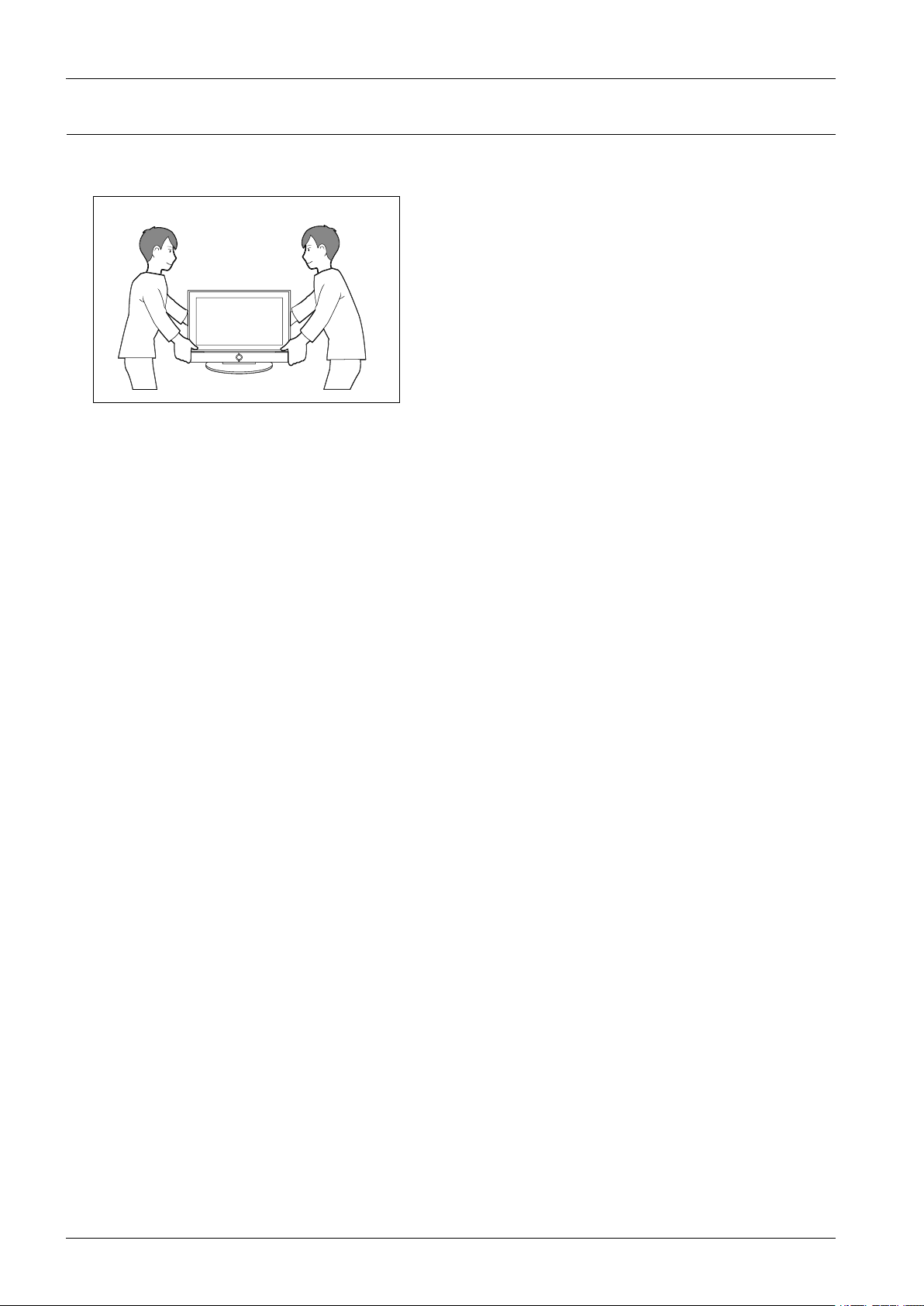
1.4.InstallationPrecautions
1)Forsafetyreasonsaminimumoftwopeoplearerequiredtocarrythisproduct.
2)Keepthepowercordawayfromanyheatemittingdevices,asameltedcoveringmaycausereorelectricshock.
3)Donotplacetheproductinareaswithpoorventilationsuchasabookshelforcloset.Theincreasedinternaltemperature
maycausere.
4)Bendtheexternalantennacablewhenconnectingittotheproduct.Thisisameasuretoprotectitfrombeingexposedto
moisture.Otherwise,itmaycauseareorelectricshock.
5)Makesuretoturnthepoweroffandunplugthepowercordfromtheoutletbeforerepositioningtheproduct.Also
checktheantennacableortheexternalconnectorsiftheyarefullyunplugged.Damagetothecordmaycausere
orelectricshock.
6)Keeptheantennafarawayfromanyhigh-voltagecablesandinstallitrmly.Contactwiththehigh-voltagecableorthe
antennafallingovermaycausereorelectricshock.
7)WhenconnectingtheRFantenna,checkforaDTVreceivingsystemandinstallaseparateDTVreceptionantennafor
areaswithnoDTVsignal.
8)Wheninstallingtheproduct,leaveenoughspace(4”)betweentheproductandthewallforventilationpurposes.A
riseintemperaturewithintheproductmaycausere.
9)WhenmovingaPDPwithremovablespeakers,detachthespeakersrstbeforemovingthemainbody.MovingthePDP
mainbodywithoutseparatingthespeakersmaycausethespeakerstodetach,possiblycausingdamageorinjury.
1-5Copyright©1995-2013SAMSUNG.Allrightsreserved.
2.ProductSpecication
2.ProductSpecication
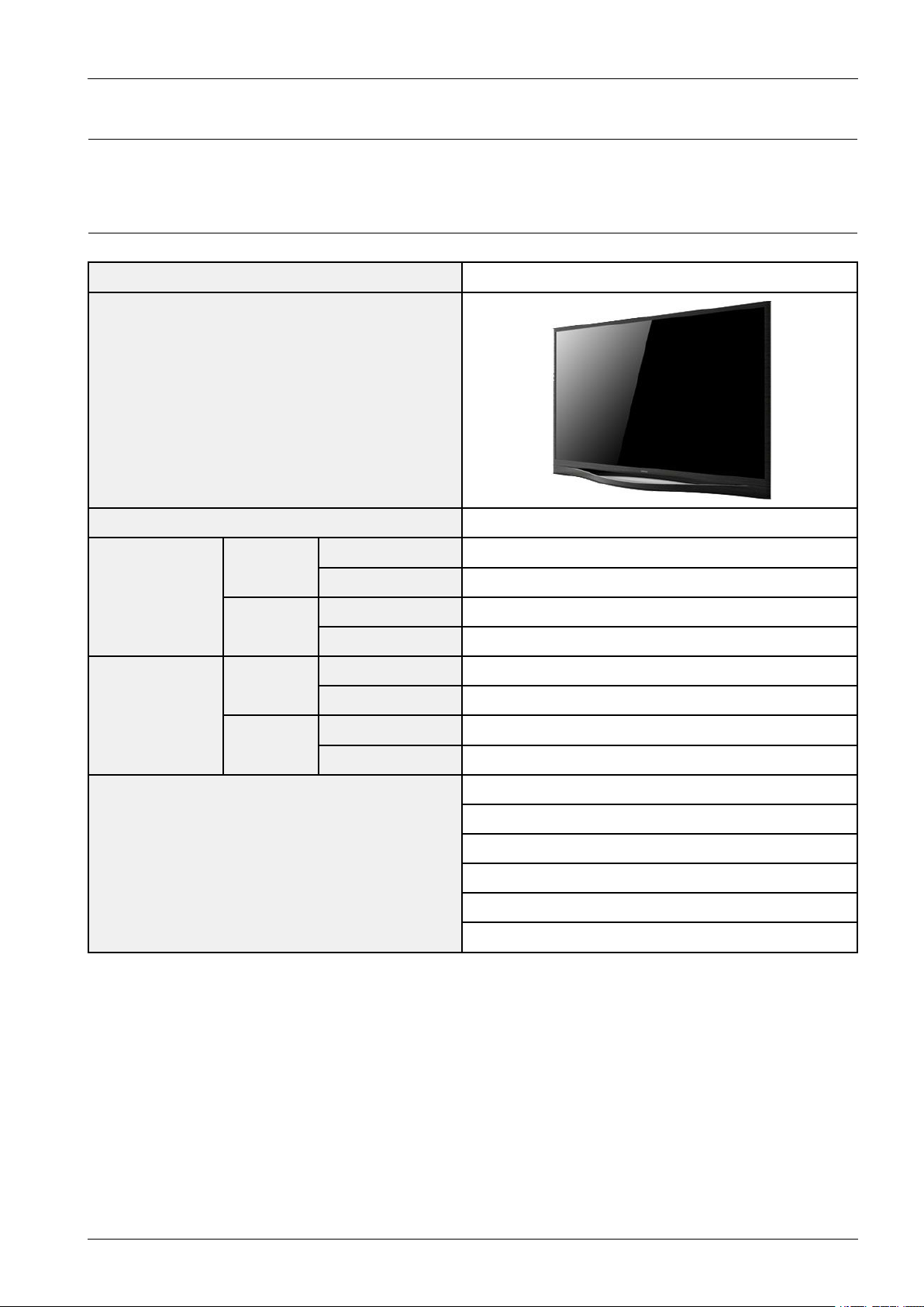
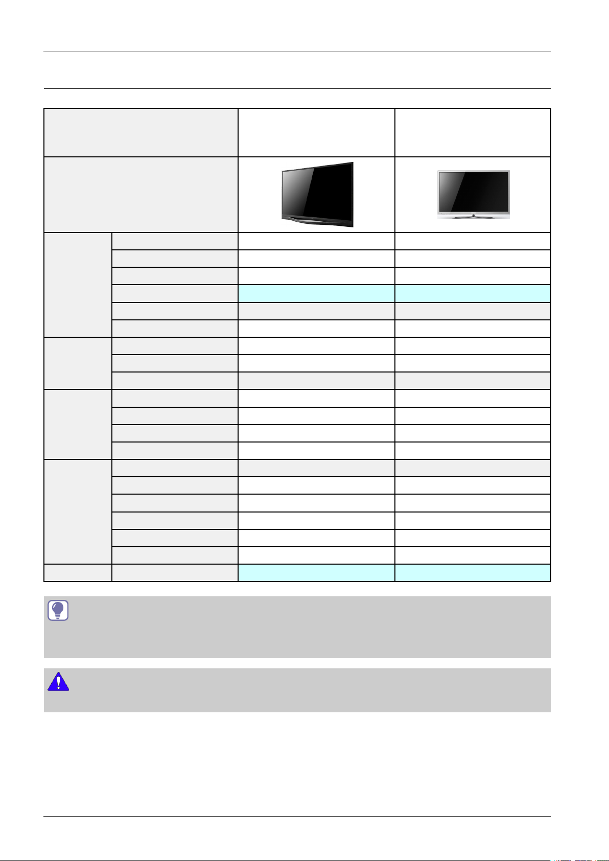
2.1.ModelComparison
SeriesPE8500
FrontView
Dimensions
WxDxH
(inch)
Weight
(lbs)
FrontColorBlack
WithoutStand46.87x27.88x1.91
51"
WithStand46.87x29.27x10.63
WithoutStand58.37x34.56x1.91
64"
WithStand58.37x36.14x12.6
WithoutStand20.9kg
51"
WithStand23.4kg
WithoutStand32.8kg
64"
WithStand36.3kg
PremiumDisplayPanel
Outstandingpremium
Anynet+(HDMI-CEC)
Feature
SMARTInteraction
Miracast
Allshare(ScreenMirroring/ContentsSharing)
Copyright©1995-2013SAMSUNG.Allrightsreserved.2-1
2.ProductSpecication
2.2.Feature&Specications
■Features
•Digital-TV ,RF,4HDMI,1-Component(A V),3-USB2.0(MediaPlay),Optical,Lan
•Brightness:1500cd/m2
•ContrastRatio:10000:1
•DolbyDigital+,SRStheater
Model
PDPPanelPremiumDisplayPanel
ScanningFrequency
DisplayColors16.7Mcolor
MaximumResolution
InputSignalAnalog0.7Vp-p±5%positiveat75Ω,internallyterminated
InputSyncSignalH/VSeparate,TTL,P .orN.
MaximumPixelClock
rate
Environmental
Considerations
MAXInternalAudioOutputPower:Each3W(Left/Right)
AudioSpec
Horizontal:60kHz~73kHz(Automatic)
Vertical:47Hz~63Hz(Automatic)
OperatingT emperature:32˚F~122˚F(0˚C~50˚C)
OperatingHumidity:20%~90%
StorageT emperature:-4˚F~140˚F(-20˚C~60˚C)
StorageHumidity:10%~90%
OutputFrequency:RF:20Hz~15.4kHz
A V/Componet/HDMI:20Hz~20kHz
PN51F8500
PN64F8500
Horizontal:1920Pixels
Vertical:1080Pixels
74.25MHz
Equalizer:5band
NOTE
DolbyDigital+,GameMode,FilmMode,EnergySaving,Anynet+,3DBuilt-In,E-Manual.
2-2Copyright©1995-2013SAMSUNG.Allrightsreserved.
■Specication
ModelPN51F8500PN64F8500
DisplayResolution1920x1080
EnvironmentalConsiderations
OperatingTemperature
OperatingHumidityStorage
TemperatureStorageHumidity
StandSwivel(Left/Right)0˚
50°Fto104°F(10°Cto40°C)10%to80%,non-condensing-4°Fto113°F
(-20°Cto45°C)5%to95%,non-condensing
2.ProductSpecication
Dimensions
(WxHxD)
Weight
Body1190.5x708.2x55.4mm1482.6x877.7x55.4mm
WithStand1190.5x743.5x270.0mm1482.6x918.0x320.0mm
WithStand23.4kg36.2kg
WithoutStand20.9kg32.8kg
ScreenSize51inches64inches
Sound(Output)10Wx2
Copyright©1995-2013SAMSUNG.Allrightsreserved.2-3
2.ProductSpecication
2.3.SpecicationsAnalysis
Model
Design
DisplayTypePDPTVPDPTV
Built-InT unerOO
Resolution1920X10801920X1080
Basic
PDPModuleFPES
ScreenSize51"/64"51"/60"/64"
Pictureratio16:916:9
Brightness1500cd/m21500cd/m2
ContrastRatio40000:140000:1 Picture
PictureEnhancerDNIeDNIe
Equalizer5Band5Band
PN51F8500
PN64F8500
PN51E8000
PN60E8000
PN64E8000
Audio
Features
ConnectionsAntenna1(Cable/Air)-P AL(Air):EU1(Cable/Air)-NTSC(Air):US,KR
TIP
O:Supported
X:NotSupported
NOTE
Forthepowersupplyandpowerconsumption,refertothelabelattachedtotheproduct.
AutoV olumeControlOO
SurroundSoundSRSTruSurroundHDSRSTruSurroundHD
SpeakerOutput10W+10W(15W+15W)10W+10W(15W+15W)
PIPOO
CaptionOO
EntertainmentModeOO
GameModeOO
EnergySavingOO
Anynet+OO
2-4Copyright©1995-2013SAMSUNG.Allrightsreserved.
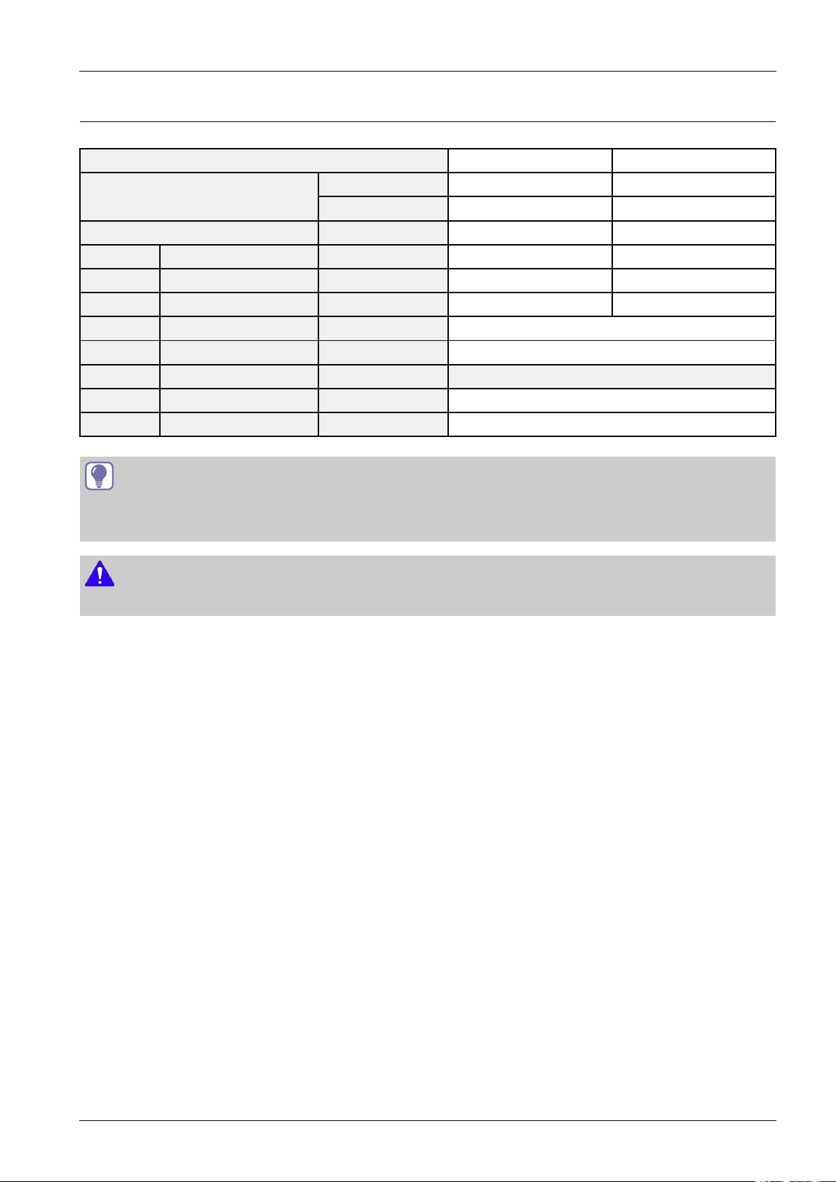
2.4.DetailFactoryOption
2.ProductSpecication
ModelPN51F8500PN64F8500
Panel
SMPSPDBoardBN44-00619ABN44-00603A
ByteItemItem
0FactoryReset---
1Type51FPCrD64FPCrD
2Localset-SelectyourLocalSet
3Model-PF8500
4Tuner-Auto
5ChT able-None
6FrontColorON/OFFP-D-G-Dy
TIP
O:Supported
X:NotSupported
NOTE
VendorSDISDI
CodeBN96-25802ABN96-25804A
Forthepowersupplyandpowerconsumption,refertothelabelattachedtotheproduct.
Copyright©1995-2013SAMSUNG.Allrightsreserved.2-5
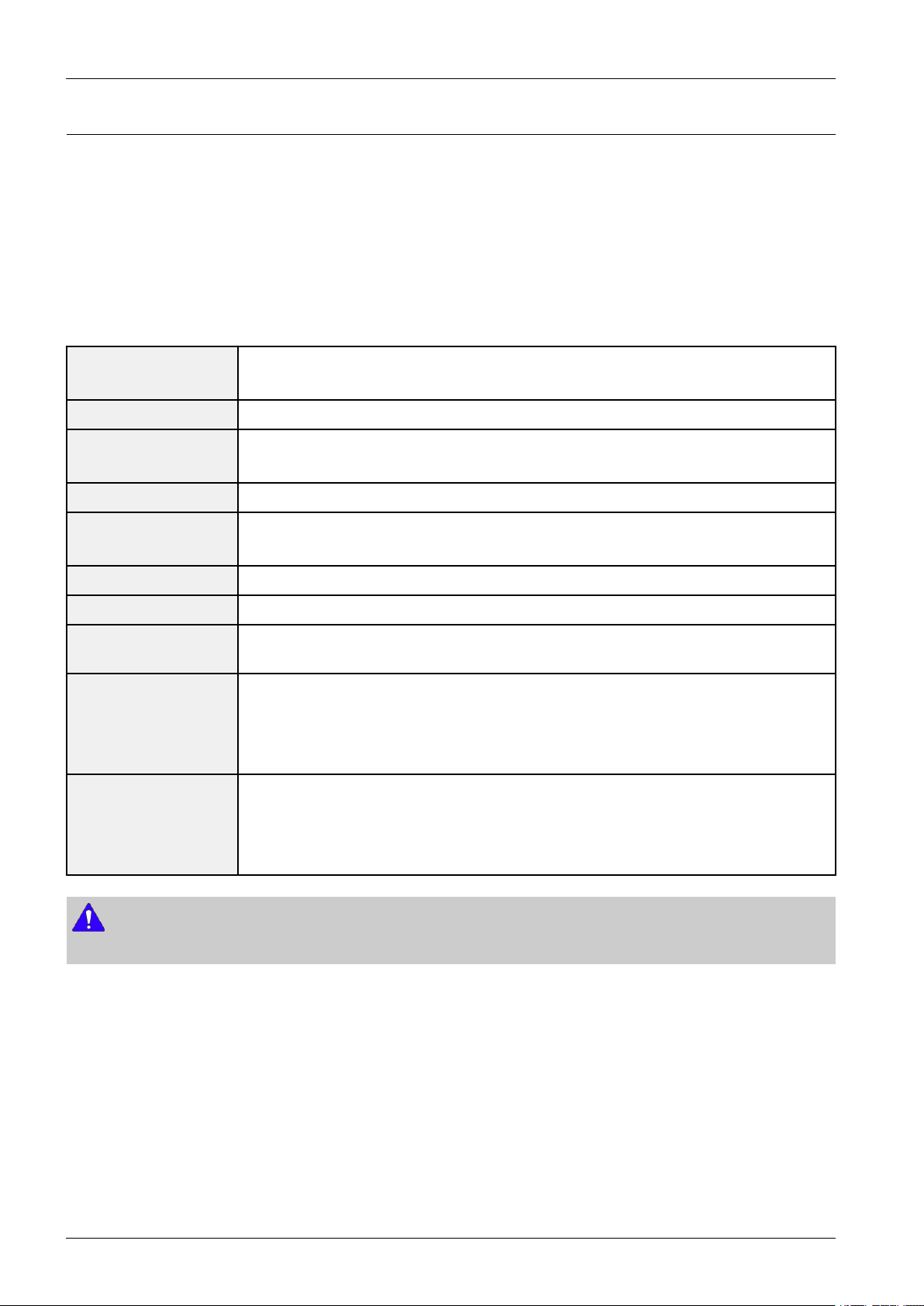
2.ProductSpecication
TV
MIC
STB
SOURCE
VOICE
MORE
VOL
CH
LIGHT DVR MENU 3D
SMART HUB
GUIDERETURN
EXIT
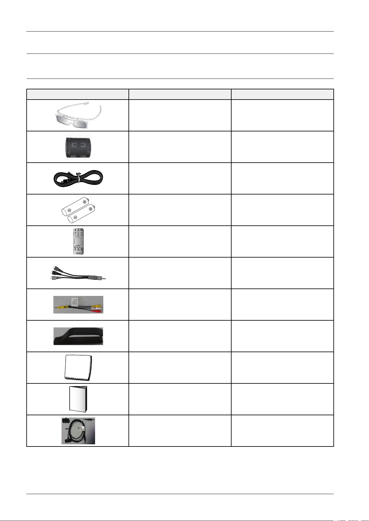
2.5.Accessories
2.5.1.SuppliedAccessories
AccessoriesItemItemcode
3DGlassesBN96-25614A
FerriteCore3301-002053
PowerCord3903-000834
Batteries(AAAx2)4301-000103
RemoteControlAA59-00759A
ComponentVideoBN39-01154C
ComponentAudioBN39-01154H
HolderWireBN61-08951A
CleaningClothBN63-01798B
Owner`sInstructionsBN68-04828G
IRExtenderCableBN96-26652A
2-6Copyright©1995-2013SAMSUNG.Allrightsreserved.
3.DisassemblyandReassembly
3.DisassemblyandReassembly
ThissectionoftheservicemanualdescribesthedisassemblyandreassemblyproceduresforthePDPTV .
WARNING
ThisPDPTVcontainselectrostaticallysensitivedevices.Usecautionwhenhandlingthesecomponents.
3.1.OverallDisassemblyandReassembly
CAUTION
•DisconnectthePDPTVfromthepowersourcebeforedisassembly.
•Followthesedirectionscarefully;neverusemetalinstrumentstopryapartthecabinet.
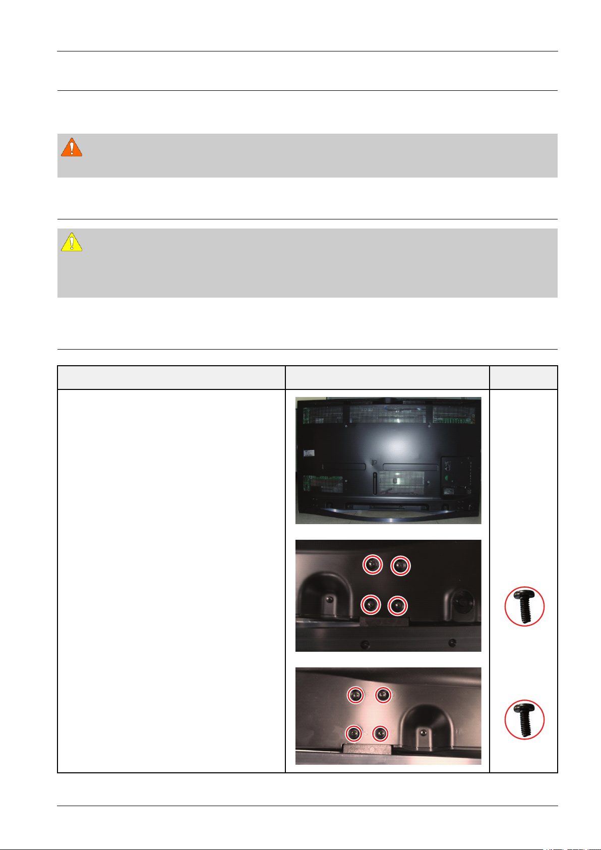
3.1.1.SeparationofSTANDP-BASE
DescriptionDescriptionPhotoScrew
1.Placemonitorfacedownoncushionedtable.
RemovescrewsfromtheStand.
Removestand.
6003–000337
M4*L10
6003–000337
M4*L10
Copyright©1995-2013SAMSUNG.Allrightsreserved.3-1
3.DisassemblyandReassembly
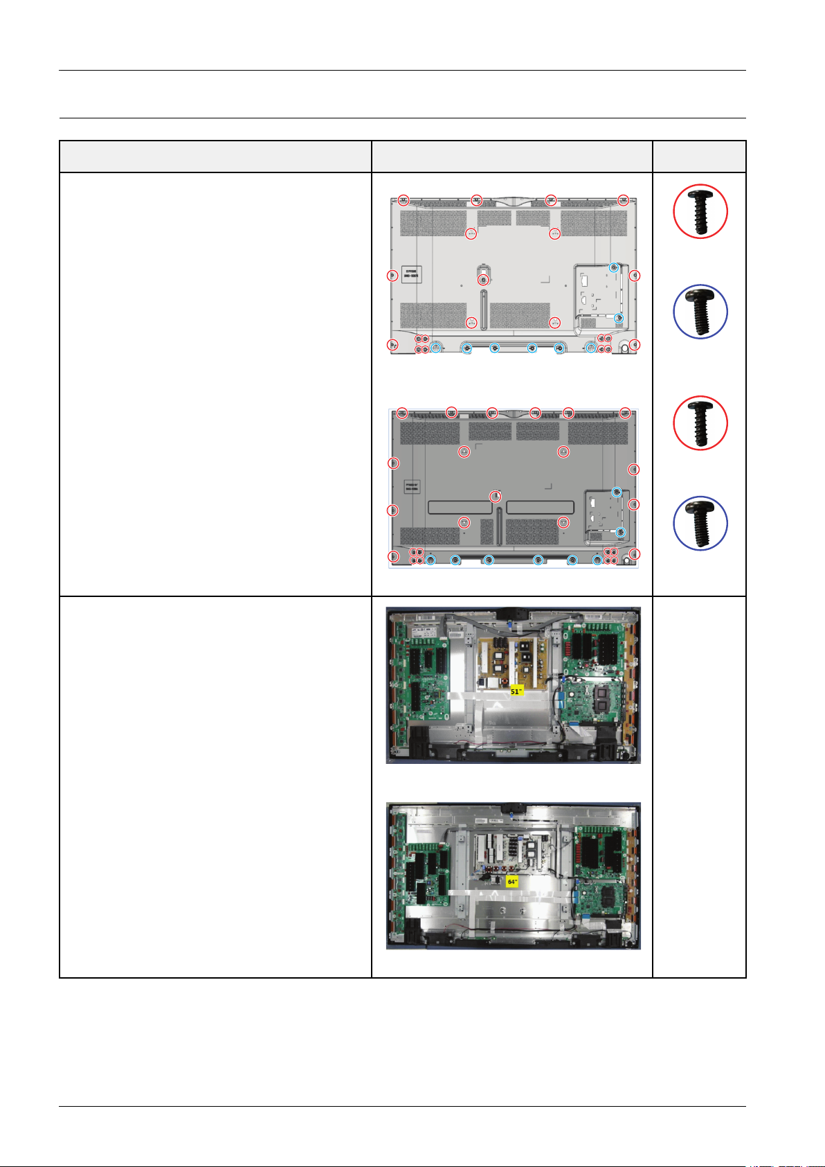
3.1.2.SeparationofASSYCOVERP-REAR
DescriptionDescriptionPhotoScrew
1.Removethescrewsofrear-cover.
6003–001782
M4*L12
6003–000337
<51">
M4*L10
6003–001782
M4*L12
2.Liftupandremovetherear-cover.
6003–000337
<64">
<51">
<64">
M4*L10
3-2Copyright©1995-2013SAMSUNG.Allrightsreserved.
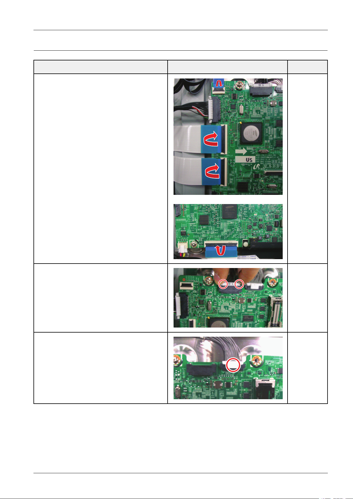
3.1.3.SeparationofASSYMAINBOARD
DescriptionDescriptionPhotoScrew
1.RemovetheFFCCable
Pullthecoverplate
Pulloutthecablegently
※TherearefourkindsofFFCcables
a)Y -maintomainboard(30p-FFCCable)
b)E-addressbuffertomainboard(60p-FFCCable)
c)F-addressbuffertomainboard(80p-FFCCable)
d)MoIPCameraCable(20p-FFCCable)
3.DisassemblyandReassembly
2.RemovePowerHarness
-Pulloutthecablepushingindicatedarea.
3.RemovetheX-mainHarness
-Pulloutthecablepushingindicatedarea.
Copyright©1995-2013SAMSUNG.Allrightsreserved.3-3
3.DisassemblyandReassembly
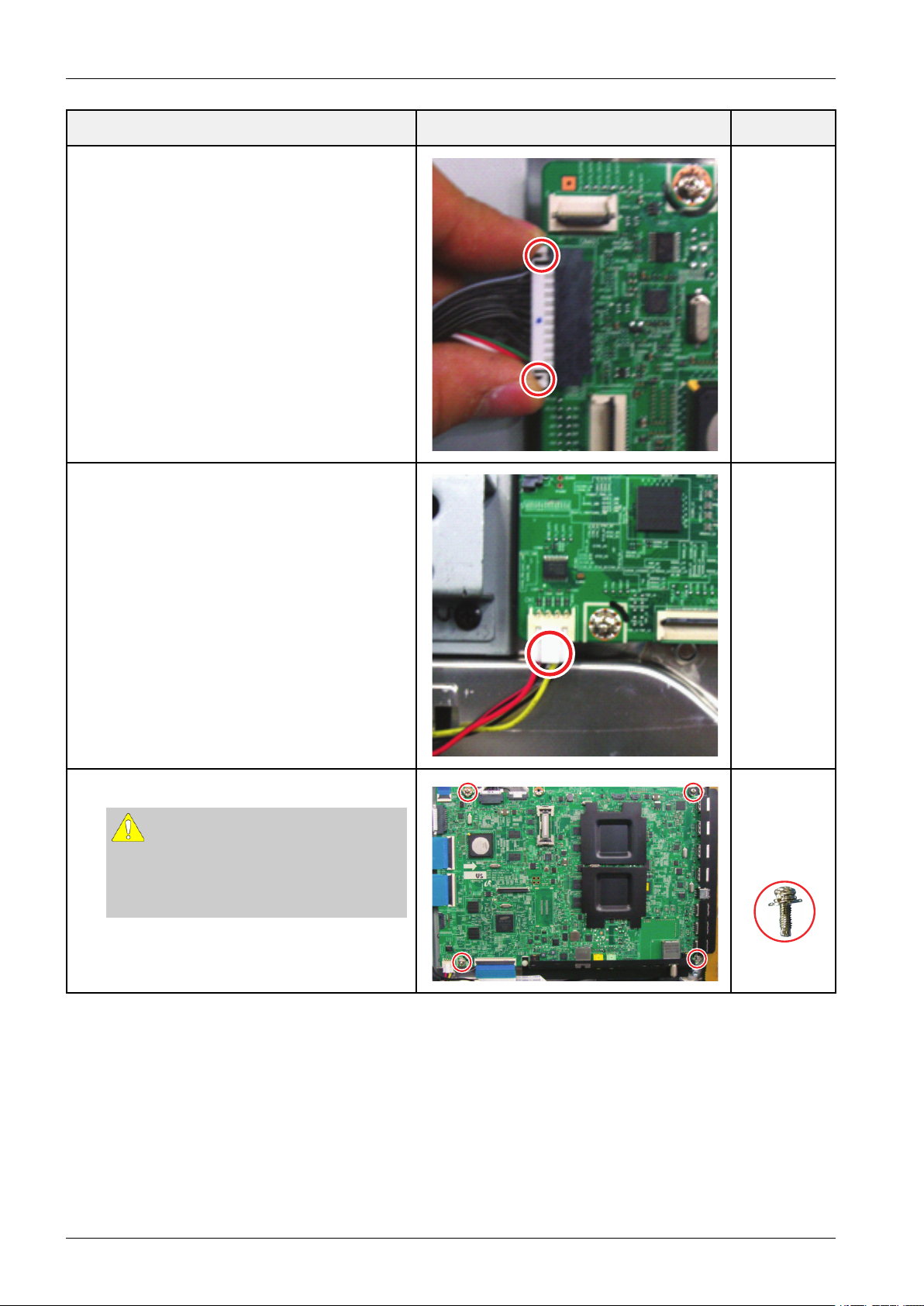
DescriptionDescriptionPhotoScrew
4.RemoveFunctionCable
-Pulloutthecablepushingindicatedarea.
5.RemoveSpeakerCable
-Pulloutthecablepushingindicatedarea.
6.Removethescrewsofmainboard.
CAUTION
WhenyouremoveBoards,youmust
disconnectallconnectors.
Ifyoudon't,itcancauseproblems.
6001–002606
M3*L10
3-4Copyright©1995-2013SAMSUNG.Allrightsreserved.
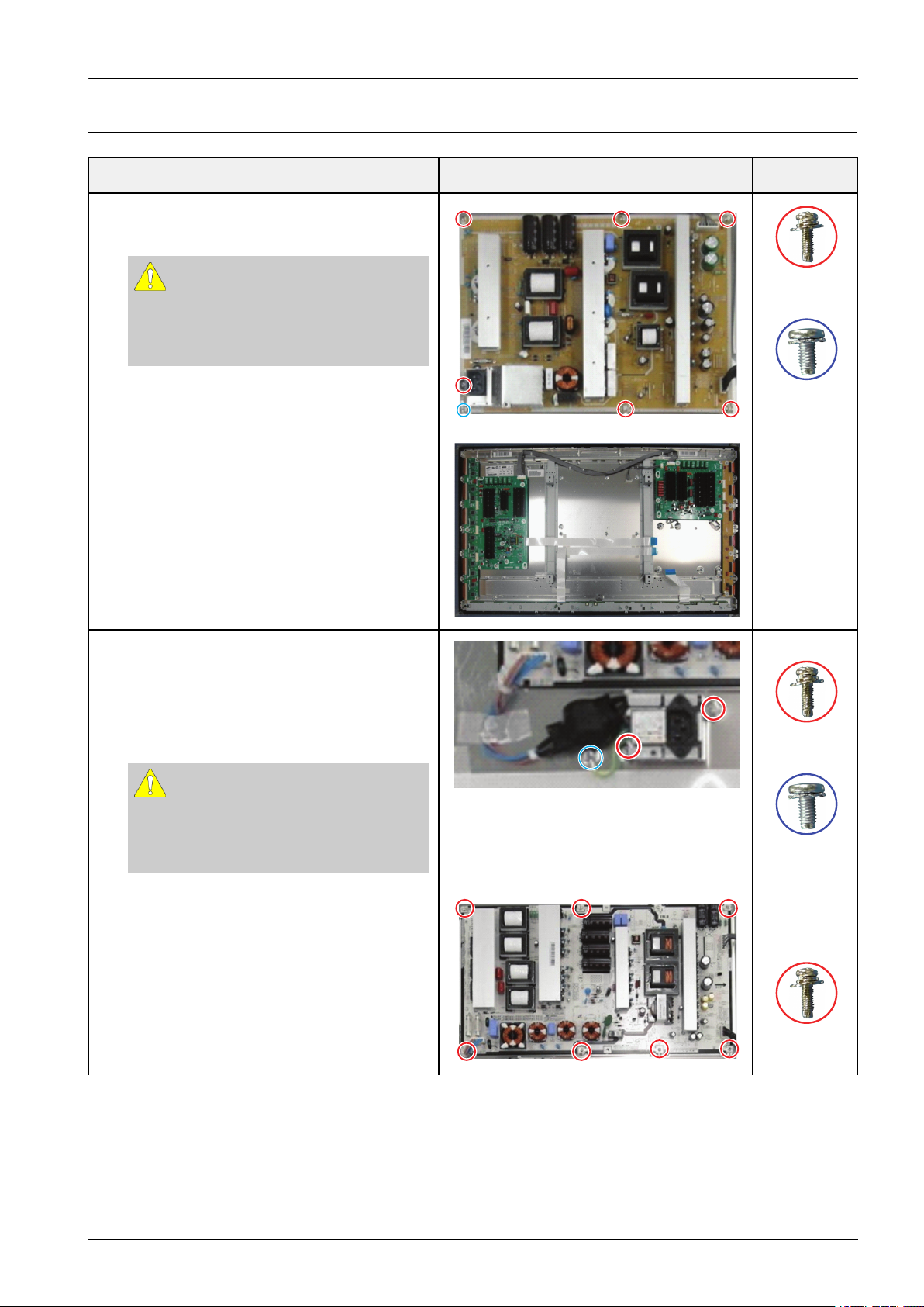
3.1.4.SeparationofSMPS
1.RemovethescrewsofSMPS.
RemovetheSMPS.
3.DisassemblyandReassembly
DescriptionDescriptionPhotoScrew
CAUTION
WhenyouremoveBoards,youmust
disconnectallconnectors.
Ifyoudon't,itcancauseproblems.
2.<64">
RemovethescrewsofACInlet.
RemovetheACInlet.
RemovethescrewsofSMPS
RemovetheSMPS
6001–002606
M3*L10
6003–001439
M3*L10
6001–002606
M3*L10
CAUTION
WhenyouremoveBoards,youmust
disconnectallconnectors.
Ifyoudon't,itcancauseproblems.
6003–001439
M3*L10
6001–002606
M3*L10
Copyright©1995-2013SAMSUNG.Allrightsreserved.3-5
3.DisassemblyandReassembly
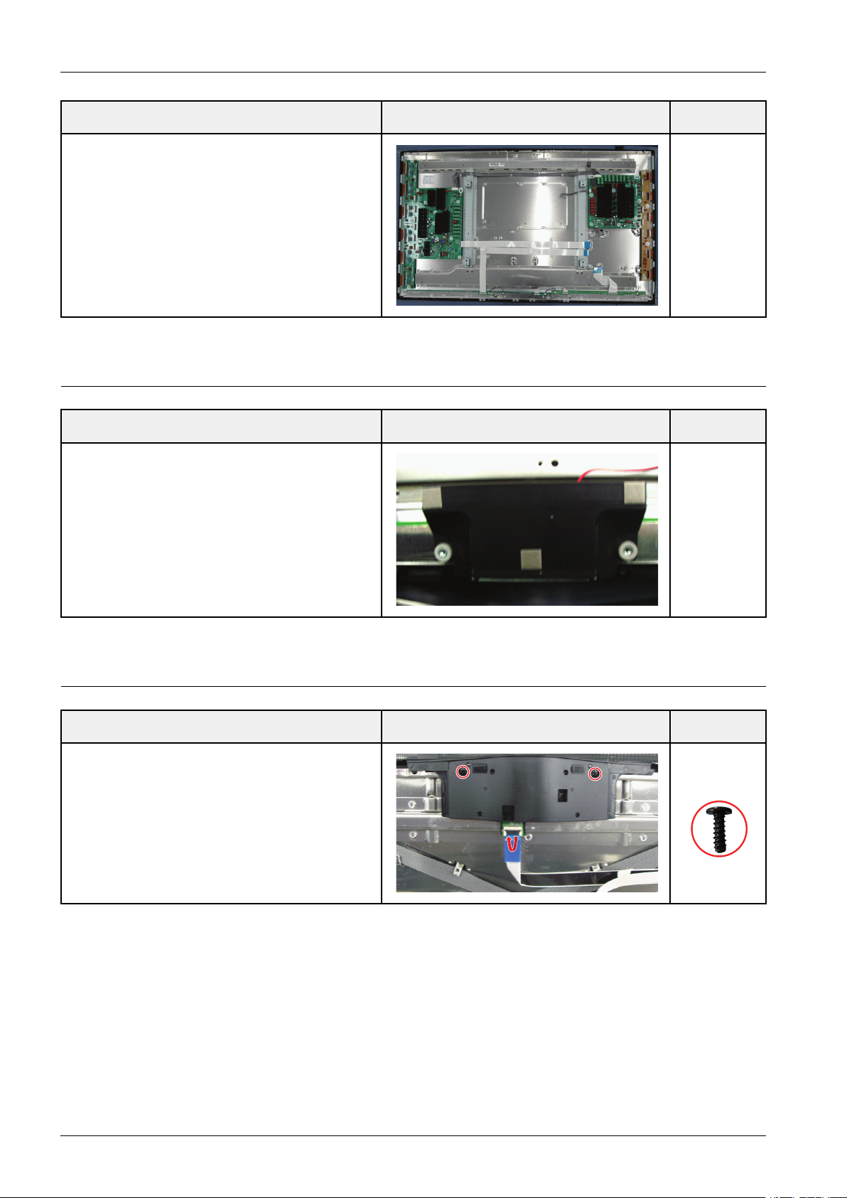
3.1.5.SeparationofSPEAKER
1.Seperatethespeakers(R/L)
DescriptionDescriptionPhotoScrew
DescriptionDescriptionPhotoScrew
3.1.6.SeparationofMolPCamera
DescriptionDescriptionPhotoScrew
1.Removescrew
Pulloutcablepushingindicatedarea
6003–001782
M4*L12
3-6Copyright©1995-2013SAMSUNG.Allrightsreserved.
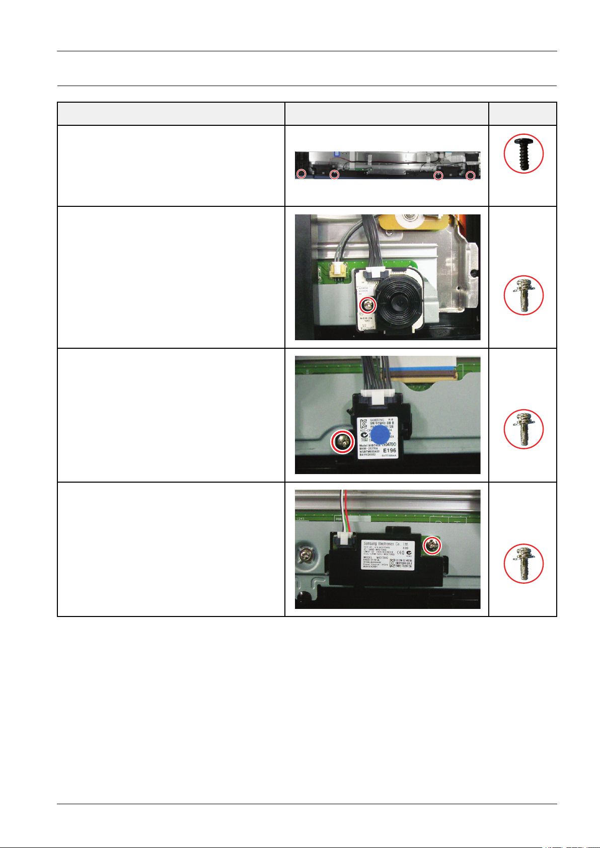
3.1.7.SeparationofFunction/Blutetoothmodule/WIFImodule
DescriptionDescriptionPhotoScrew
1.*Separatethecover-speaker
2.*Seperationoffunctionmodule
Removescrew
Pulloutcablepushingindicatedarea
3.DisassemblyandReassembly
6003–001782
M4*L12
6001–002606
M3*L10
3.*SeperationofBTmodule.
Removescrew
Pulloutcablepushingindicatedarea.
4.*SeperationofWIFImodule.
Removescrew
Pulloutcablepushingindicatedarea.
6001–002606
M3*L10
6001–002606
M3*L10
Copyright©1995-2013SAMSUNG.Allrightsreserved.3-7
3.DisassemblyandReassembly
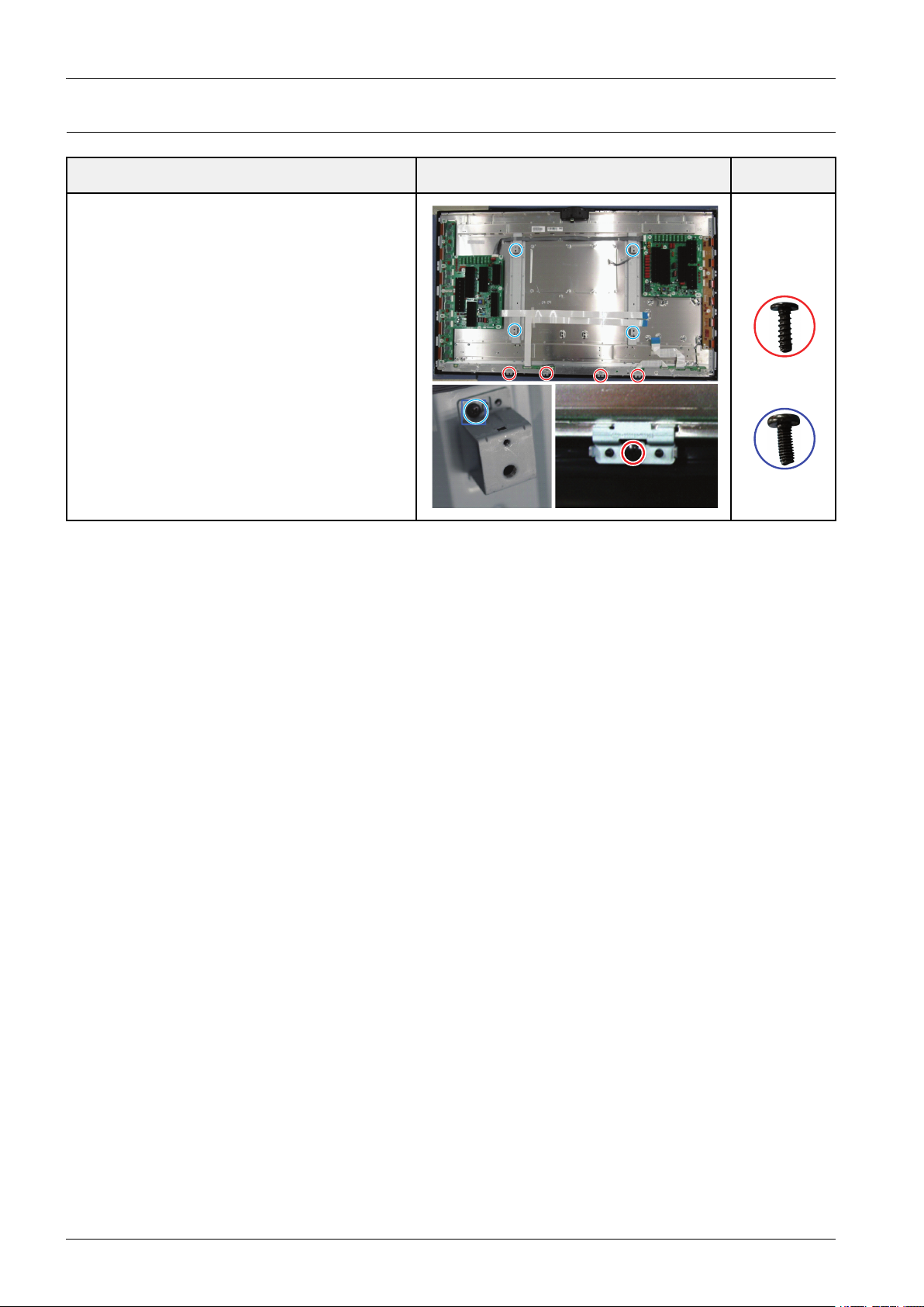
3.1.8.SeparationofBracketWall/Bracketmodule
DescriptionDescriptionPhotoScrew
1.RemovescrewsoftheBracketWallandBracket
Module.(60",64")
Thebracketmodulesarenotexistedin51-inch
models
6003–001782
M4*L12
6003–000337
M4*L10
3-8Copyright©1995-2013SAMSUNG.Allrightsreserved.
 Loading...