

Page 1

PlasmaTV
ChassisF5KA
ModelCodePN64F5500AFXZA
MANUAL
SERVICE
PlasmaTV
1.Precaution
2.ProductSpecication
3.DisassemblyandReassembly
4.Troubleshooting
5.WiringDiagram
PN64F5500AF
Contents
RefertotheservicemanualintheGSPN(seetherearcover)formoreinformation.
Page 2

Contents
Contents
1.Precaution........................................................................................................................................1−1
1.1.SafetyPrecautions...................................................................................................................1−1
1.2.ServicingPrecautions...............................................................................................................1−3
1.3.StaticElectricityPrecautions......................................................................................................1−4
1.4.InstallationPrecautions.............................................................................................................1−5
2.ProductSpecication.........................................................................................................................2−1
2.1.ModelComparison...................................................................................................................2−1
2.2.Feature&Specications...........................................................................................................2−2
2.3.SpecicationsAnalysis.............................................................................................................2−3
2.4.Accessories............................................................................................................................2−4
2.4.1.SuppliedAccessories...................................................................................................2−4
3.DisassemblyandReassembly..............................................................................................................3−1
3.1.OverallDisassemblyandReassembly..........................................................................................3−1
4.Troubleshooting................................................................................................................................4−1
4.1.FirstChecklistforTroubleshooting.............................................................................................4−1
4.2.CheckpointsbyErrorMode.......................................................................................................4−2
4.2.1.ExampleofTroubleShooting........................................................................................4−9
4.2.2.OperatingLogicLED...................................................................................................4−11
4.3.FactoryModeAdjustments........................................................................................................4−13
4.3.1.DetailFactoryOption...................................................................................................4−13
4.3.2.EnteringFactoryMode.................................................................................................4−14
4.3.3.FactoryData...............................................................................................................4−16
4.4.WhiteBalance–Calibration......................................................................................................4−29
4.4.1.WhiteBalance-Calibration...........................................................................................4−30
4.4.2.ServiceAdjustment......................................................................................................4−30
4.4.3.WhiteBalance-Adjustment..........................................................................................4−32
4.5.SoftwareUpgrade....................................................................................................................4−33
4.6.RS-232C................................................................................................................................4−34
4.7.A Vcontrolcode.......................................................................................................................4−35
4.8.RearCoverDimension..............................................................................................................4−40
5.WiringDiagram................................................................................................................................5−1
5.1.OverallWiring........................................................................................................................5−1
5.1.1.PinConnection...........................................................................................................5−5
iCopyright©1995-2013SAMSUNG.Allrightsreserved.
Page 3
1.Precaution
DEVICE
UNDER
TEST
LEAKAGE
CURREN T
TESTER
TES T ALL
EXPOSED ME TAL
SUR FACES
2-WIRE CORD
ALSO TES T WITH
PLUG REVERSED
(US ING AC
ADAPTER PLUG
AS REQU IRED)
EARTH
GR OUND
( R E A D I N G
SHOULD NOT BE
ABOVE 0.5mA)
1.Precaution
Toavoidpossibledamage,electricshocksorexposuretoradiation,followtheinstructionsbelowwithregardtosafety,
installation,serviceandESD.
1.1.SafetyPrecautions
1)Makesureallprotectivedevicesareproperlyinstalledincludingnon-metallichandlesandcompartmentcoverswhen
installingorre-installingthechassisorchassisassemblies.
2)Makesurethatnogapsexistbetweenthecabinetsforchildrentoinserttheirngersintopreventchildrenfrom
receivingelectricshocks.GapsmentionedaboveincludeventilationholesofatoogreatmagnitudebetweenthePDP
moduleandthecabinetmask,andtheimproperinstallationoftherearcabinet.
Errorsmayoccurwhentheresistanceisbelow1.0MΩorover5.2MΩ.Inthesecases,makesurethatthedeviceis
repairedbeforesendingitbacktothecustomer.
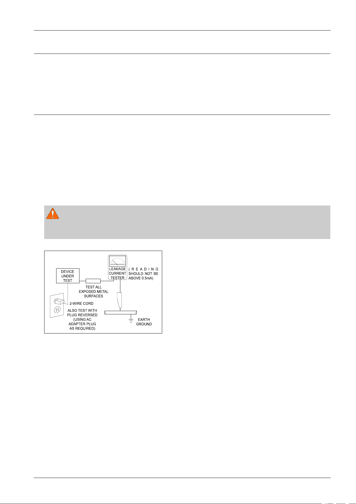
3)CheckforElectricityLeakage(ACLeakageT est)
WARNING
Donotuseaninsulatedtransformerforcheckingtheleakage.Useonlythosecurrentleakagetestersormirroring
systemsthatcomplywithANSIC101.1andtheUnderwriterLaboratory’sspecications(UL1410,59.7).
Figure1.1ACLeakageT est
4)Ahighvoltageismaintainedwithinthespeciedlimitsusingsafetyparts,calibrationandtolerances.Whenvoltage
exceedsthespeciedlimits,checkeachspecialpart.
5)W arningforEngineeringChanges:
Nevermakeanychangesoradditionstothecircuitdesignortheinternalpartforthisproduct.
Ex:Donotaddanyaudioorvideoaccessoryconnectors.Thismightcausephysicaldamage.
Furthermore,anychangesoradditionstotheoriginaldesign/engineeringwillinvalidatethewarranty.
6)W arning-HotChassis:
SomeTVchassisaredirectlyconnectedtooneendoftheACpowercordforelectricalreasons.Withoutinsulated
transformers,theproductcanonlyberepairedsafelywhenthechassisisconnectedtotheearthedendoftheAC
powersource.
TomakesuretheACpowercordisproperlyconnected,followtheinstructionsbelow.Usethevoltmetertomeasurethe
voltagebetweenthechassisandtheearthedground.Ifthemeasurementisover1.0V ,unplugtheACpowercordand
changethepolaritybeforereinsertingit.Measurethevoltagebetweenthechassisandthegroundagain.
Copyright©1995-2013SAMSUNG.Allrightsreserved.1-1
Page 4

1.Precaution
7)SomeTVchassisareshippedwithanadditionalsecondarygroundingsystem.Thesecondarysystemisadjacentto
theACpowerline.Thesetwogroundingsystemsareseparatedinthecircuitusinganunbreakable/unchangeable
insulationmaterial.
8)Whenanyparts,materialorwiringappearoverheatedordamaged,replacethemwithnewregularonesimmediately.
Whenanydamageoroverheatingisdetected,correctthisimmediatelyandmakearegularcheckofpossibleerrors.
9)Checkfortheoriginalshapeofthelead,especiallythatoftheantennawiring,anysharpedges,theACpowerandthe
highvoltagepower.Carefullycheckifthewiringistootight,incorrectlyplacedorloose.Neverchangethespace
betweenthepartandtheprintedcircuitboard.ChecktheACpowercordforpossibledamages.Keepthepartorthe
leadawayfromanyheat-emittingmaterials.
10)SafetyIndication:
Someelectricalcircuitsordevicerelatedmaterialsrequirespecialattentiontotheirsafetyfeatures,whichcannotbe
viewedbythenakedeye.Ifanoriginalpartisreplacedwithanotherirregularone,thesafetyorprotectivefeatureswill
belostevenifthenewonehasahighervoltageormorewatts.
Criticalsafetypartsshouldbebracketedwith(
,).Useonlyregularpartsforreplacements(inparticular,ame
resistanceanddielectricstrengthspecications).Irregularpartsormaterialsmaycauseelectricshockorre.
1-2Copyright©1995-2013SAMSUNG.Allrightsreserved.
Page 5

1.2.ServicingPrecautions
WARNING
1)Firstcarefullyreadthe“SafetyInstruction”inthisservicemanual.
Whenthereisaconictbetweentheserviceandthesafetyinstructions,followthesafetyinstructionatalltimes.
2)Anyelectrolyticcapacitorwiththewrongpolaritywillexplode.
1)Theserviceinstructionsareprintedonthecabinet,andshouldbefollowedbyanyservicepersonnel.
2)MakesuretounplugtheACpowercordfromthepowersourcebeforestartinganyrepairs.
a)Removeorre-installpartsorassemblies.
b)Disconnecttheelectricplugorconnector,ifany.
c)Connectthetestpartinparallelwiththeelectrolyticcapacitor.
3)Somepartsareplacedatahigherpositionthantheprintedboard.Insulatedtubesortapesareusedforthispurpose.
Theinternalwiringisclampedusingbucklestoavoidcontactwithheatemittingparts.Thesepartsareinstalledback
totheiroriginalposition.
4)Aftertherepair,makesuretocheckifthescrews,partsorcablesareproperlyinstalled.Makesurenodamageiscaused
totherepairedpartanditssurroundings.
1.Precaution
5)CheckforinsulationbetweenthebladeoftheACplugandthatofanyconductivematerials(i.e.themetalpanel,
inputterminal,earphonejack,etc).
6)InsulationCheckProcess:
UnplugthepowercordfromtheACsourceandturntheswitchon.Connecttheinsulatingresistancemeter(500V)to
theACplugblade.TheinsulatingresistancebetweenthebladeoftheACplugandthatoftheconductivematerial
shouldbemorethan1MΩ.
7)AnyB+interlockshouldnotbedamaged.
Ifthemetalheatsinkisnotproperlyinstalled,noconnectiontotheACpowershouldbemade.
8)Makesurethegroundingleadofthetesterisconnectedtothechassisgroundbeforeconnectingtothepositivelead.
Thegroundleadofthetestershouldberemovedlast.
9)Bewareofrisksofanycurrentleakagecomingintocontactwiththehigh-capacitycapacitor.
10)Thesharpedgesofthemetalmaterialmaycausephysicaldamage,soprotectyourselfbywearingglovesduringthe
repair.
11)Duetothenatureofplasmadisplaypanels,partialafter-imagesmayappearifastillpictureisdisplayedonthescreen
foralongperiodoftime.
Thisiscausedbybrightnessdeteriorationduetothestorageeffectofthepanel,andtopreventthisfromhappening,we
recommendthatthebrightnessandcontrastarereduced.(e.g.)Contrast:25,Brightness:50
Copyright©1995-2013SAMSUNG.Allrightsreserved.1-3
Page 6

1.Precaution
1.3.StaticElectricityPrecautions
1)Somesemi-conductive(“solidstate”)devicesarevulnerabletostaticelectricity .ThesedevicesareknownasESD.
ESDincludestheintegratedcircuitandtheeldeffecttransistor.Toavoidanymaterialsdamagefromelectrostatic
shock,followtheinstructionsdescribedbelow.
2)Removeanystaticelectricityfromyourbodybyconnectingtheearthgroundbeforehandlinganysemi-conductiveparts
orassemblies.Alternatively ,wearadischargeablewrist-belt.
(Makesuretoremoveanystaticelectricitybeforeconnectingthepowersource-thisisasafetyinstructionfor
avoidingelectricshock)
3)RemovetheESDassemblyandplaceitonaconductivesurfacesuchasaluminumfoiltopreventaccumulatingstatic
electricity.
4)DonotuseanyFreon-basedchemicals.SuchchemicalswillgeneratestaticelectricitythatcausesdamagetotheESD.
5)Useonlygrounded-tipironsforsolderingpurposes.
6)Useonlyanti-staticsolderremovaldevices.
Mostsolderremovaldevicesdonotsupportananti-staticfeature.Asolderremovaldevicewithoutananti-staticfeature
canstoreenoughstaticelectricitytocausedamagetotheESD.
7)DonotremovetheESDfromtheprotectiveboxuntilthereplacementisready.MostESDreplacementsarecoveredwith
lead,whichwillcauseashorttotheentireunitduetotheconductivefoam,aluminumfoilorotherconductivematerials.
8)RemovetheprotectivematerialfromtheESDreplacementleadimmediatelyafterconnectingittothechassisor
circuitassembly.
9)T akeextremecautioninhandlinganyuncoveredESDreplacements.Actionssuchasbrushingclothesorliftingyourleg
fromthecarpetoorcangenerateenoughstaticelectricitytodamagetheESD.
CAUTION
Theseservicinginstructionsareforusebyqualiedservicepersonnelonly.
Toreducetheriskofelectricshockdonotperformanyservicingotherthanthatcontainedintheoperatinginstructions
unlessyouarequaliedtodoso.
1-4Copyright©1995-2013SAMSUNG.Allrightsreserved.
Page 7

1.Precaution
1.4.InstallationPrecautions
1)Forsafetyreasonsaminimumoftwopeoplearerequiredtocarrythisproduct.
2)Keepthepowercordawayfromanyheatemittingdevices,asameltedcoveringmaycausereorelectricshock.
3)Donotplacetheproductinareaswithpoorventilationsuchasabookshelforcloset.Theincreasedinternaltemperature
maycausere.
4)Bendtheexternalantennacablewhenconnectingittotheproduct.Thisisameasuretoprotectitfrombeingexposedto
moisture.Otherwise,itmaycauseareorelectricshock.
5)Makesuretoturnthepoweroffandunplugthepowercordfromtheoutletbeforerepositioningtheproduct.Also
checktheantennacableortheexternalconnectorsiftheyarefullyunplugged.Damagetothecordmaycausere
orelectricshock.
6)Keeptheantennafarawayfromanyhigh-voltagecablesandinstallitrmly.Contactwiththehigh-voltagecableorthe
antennafallingovermaycausereorelectricshock.
7)WhenconnectingtheRFantenna,checkforaDTVreceivingsystemandinstallaseparateDTVreceptionantennafor
areaswithnoDTVsignal.
8)Wheninstallingtheproduct,leaveenoughspace(4”)betweentheproductandthewallforventilationpurposes.A
riseintemperaturewithintheproductmaycausere.
9)WhenmovingaPDPwithremovablespeakers,detachthespeakersrstbeforemovingthemainbody.MovingthePDP
mainbodywithoutseparatingthespeakersmaycausethespeakerstodetach,possiblycausingdamageorinjury.
Copyright©1995-2013SAMSUNG.Allrightsreserved.1-5
Page 8
2.ProductSpecication
2.ProductSpecication
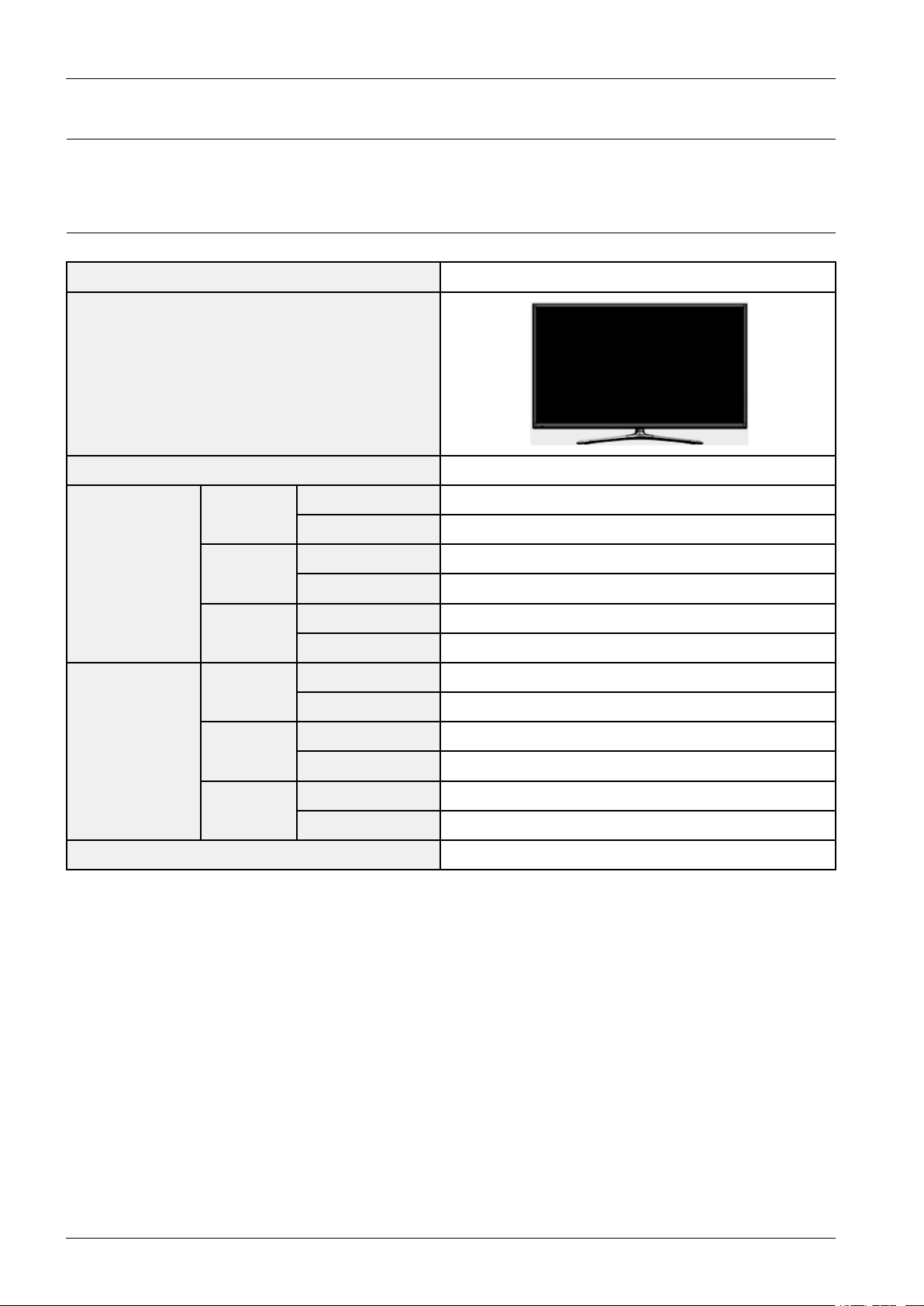
2.1.ModelComparison
SeriesPF5500
FrontView
FrontColorBlack
Dimensions
WxDxH
(inch)
Weight
(lbs)
51"
WithoutStand1191.9x57.0x709.1
WithStand1191.9x307.2x798.8
WithoutStand1396.9x57.0x831.3
60"
WithStand1396.9x375.5x928
WithoutStand1483.8x57.0x877.1
64"
WithStand1483.8x375.5x974.5
WithoutStand18.5kg
51"
WithStand26.5kg
WithoutStand27.5kg
60"
WithStand38.3kg
WithoutStand33kg
64"
WithStand44.8kg
Featuresmarttv2.0
2-1Copyright©1995-2013SAMSUNG.Allrightsreserved.
Page 9
2.2.Feature&Specications
■Features
•Digital-TV ,RF,4HDMI,1-Component(A V),3-USB2.0(MediaPlay),Optical,Lan
•Brightness:1500cd/m2
•ContrastRatio:10000:1
•DolbyDigital+,SRStheater
■Specication
ModelPN51F5500PN60F5500PN64F5500
DisplayResolution1920x1080
Environmental
Considerations
OperatingT emperature
OperatingHumidity
StorageTemperature
StorageHumidity
50°Fto104°F(10°Cto40°C)10%to80%,non-condensing-4°Fto113°F
(-20°Cto45°C)5%to95%,non-condensing
2.ProductSpecication
StandSwivel(Left
/Right)
Dimensions(WxH
xD)Body
WithStand
With
Stand
Weight
Without
Stand
ScreenSize
Sound(Output)10Wx2
46.9x27.9x2.2inches
(1191.9x709.1x57.0mm)
46.9x31.4x12.0inches
(1191.9x798.8x307.2mm)
44.7lbs(20.3kg)66.3lbs(30.1kg)78.4lbs(35.6kg)
40.7lbs(18.5kg)60.6lbs(27.5kg)72.7lbs(33.0kg)
51˝Class
(50.6measureddiagonally)
(1396.9x831.3x57.0mm)
(1396.9x928x375.5mm)
(59.9measureddiagonally)
-20˚~20˚
54.9x32.7x2.2inches
54.9x36.5x14.7inches
58.4x34.5x2.2inches
(1483.8x877.1x57.0mm)
58.4x38.3x14.7inches
(1483.8x974.5x375.5mm)
60˝Class
(64.0measureddiagonally)
64˝Class
Copyright©1995-2013SAMSUNG.Allrightsreserved.2-2
Page 10
2.ProductSpecication
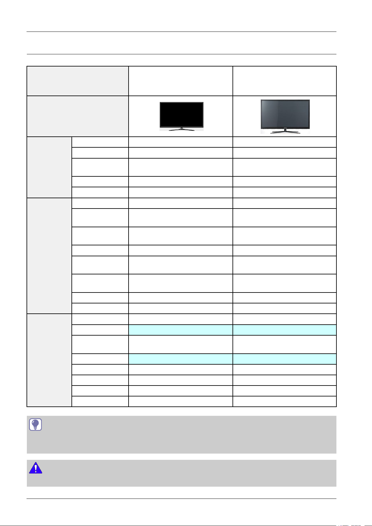
2.3.SpecicationsAnalysis
Model
Design
PN51F5500
PN60F5500
PN64F5500
DisplayT ypePDPTVPDPTV
Resolution1,920x1,0801920X1080
PN51E550
Basic
Picture
PremiumDisplay
Panel
RealBlackProPanelXX
ClearImagePanelOO
PictureEngine3DHyperRealEngine3DHyperRealEngine
600HzSubeld
Motion
DynamicContrast
Ratio
CinemaSmoothOO
MotionJudder
Canceller
WideColorEnhancer
(Plus)
FilmModeOO
RelaxModeSupportXX
DolbyDolbyDigitalPlus/PulseDolbyDigitalPlus/Pulse
SRS/DNSe+SRSTheaterSound3DSRSTheaterSoundHD
dts2.0+DigitalOut/
DTSPremiumAudio
DTSPremiumAudioDTSPremiumAudio
X
O
MegaDCR
X
O
MegaDCR
X
O
X
O
Audio
TIP
O:Supported
X:NotSupported
NOTE
Forthepowersupplyandpowerconsumption,refertothelabelattachedtotheproduct.
2-3Copyright©1995-2013SAMSUNG.Allrightsreserved.
3DSoundOX
SoundCustomizerXX
SpeakerT ypeDownFiring+FullRangeDownFiring+FullRange
SoundOutput(RMS)10Wx210WX2
WooferXX
Page 11
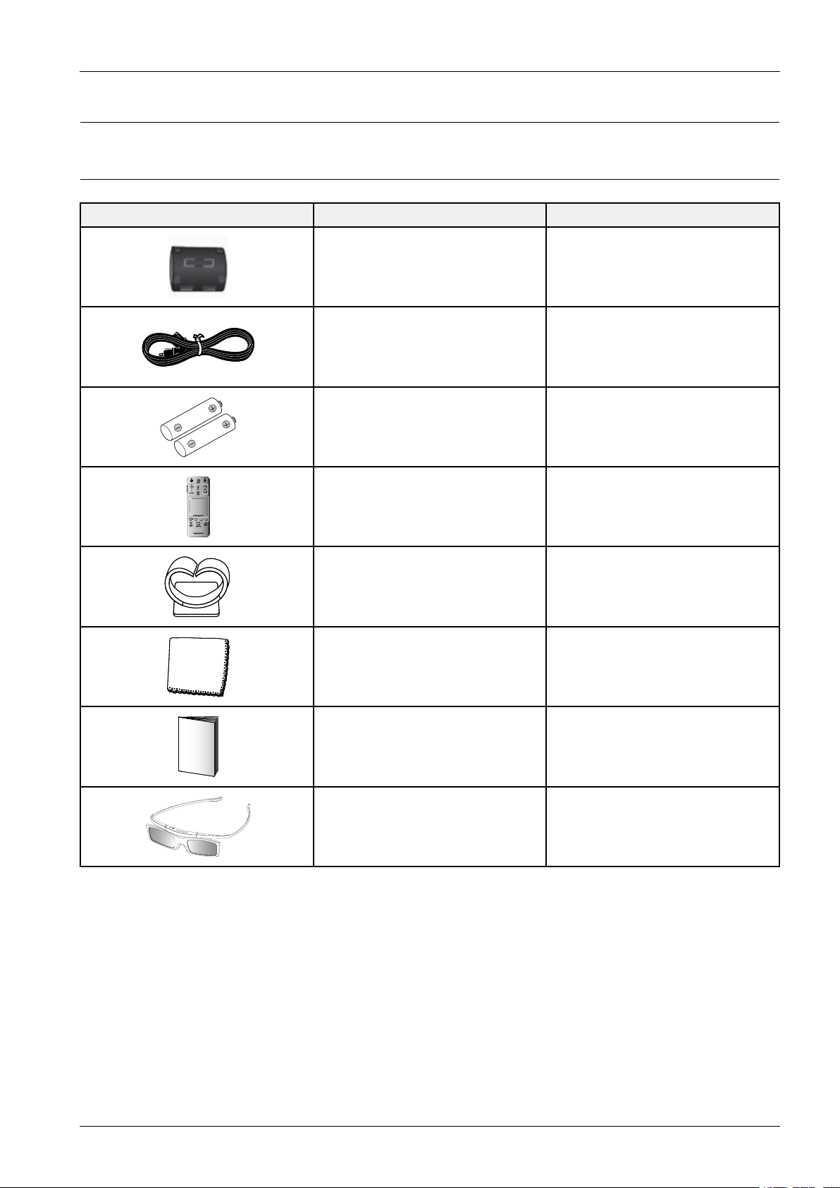
2.4.Accessories
TV
MIC
STB
SOURCE
VOICE
MORE
VOL
CH
LIGHT DVR MENU 3D
SMART HUB
GUIDERETURN
EXIT
2.4.1.SuppliedAccessories
2.ProductSpecication
AccessoriesItemItemcode
FerriteCore3301-002049
PowerCord3903-000552
Batteries(AAAx2)4301-000103
RemoteControlAA59-00772A
StandWireHolderBN61-08370A
CleaningClothBN63-02368B
Owner`sInstructionsBN68-04891A
3DGlassesBN96-25614A
Copyright©1995-2013SAMSUNG.Allrightsreserved.2-4
Page 12
3.DisassemblyandReassembly
3.DisassemblyandReassembly
ThissectionoftheservicemanualdescribesthedisassemblyandreassemblyproceduresforthePDPTV .
WARNING
ThisPDPTVcontainselectrostaticallysensitivedevices.Usecautionwhenhandlingthesecomponents.
3.1.OverallDisassemblyandReassembly
CAUTION
•DisconnectthePDPTVfromthepowersourcebeforedisassembly.
•Followthesedirectionscarefully;neverusemetalinstrumentstopryapartthecabinet.
•Ifthereisnoadditionalcomment,itissameforallinches.
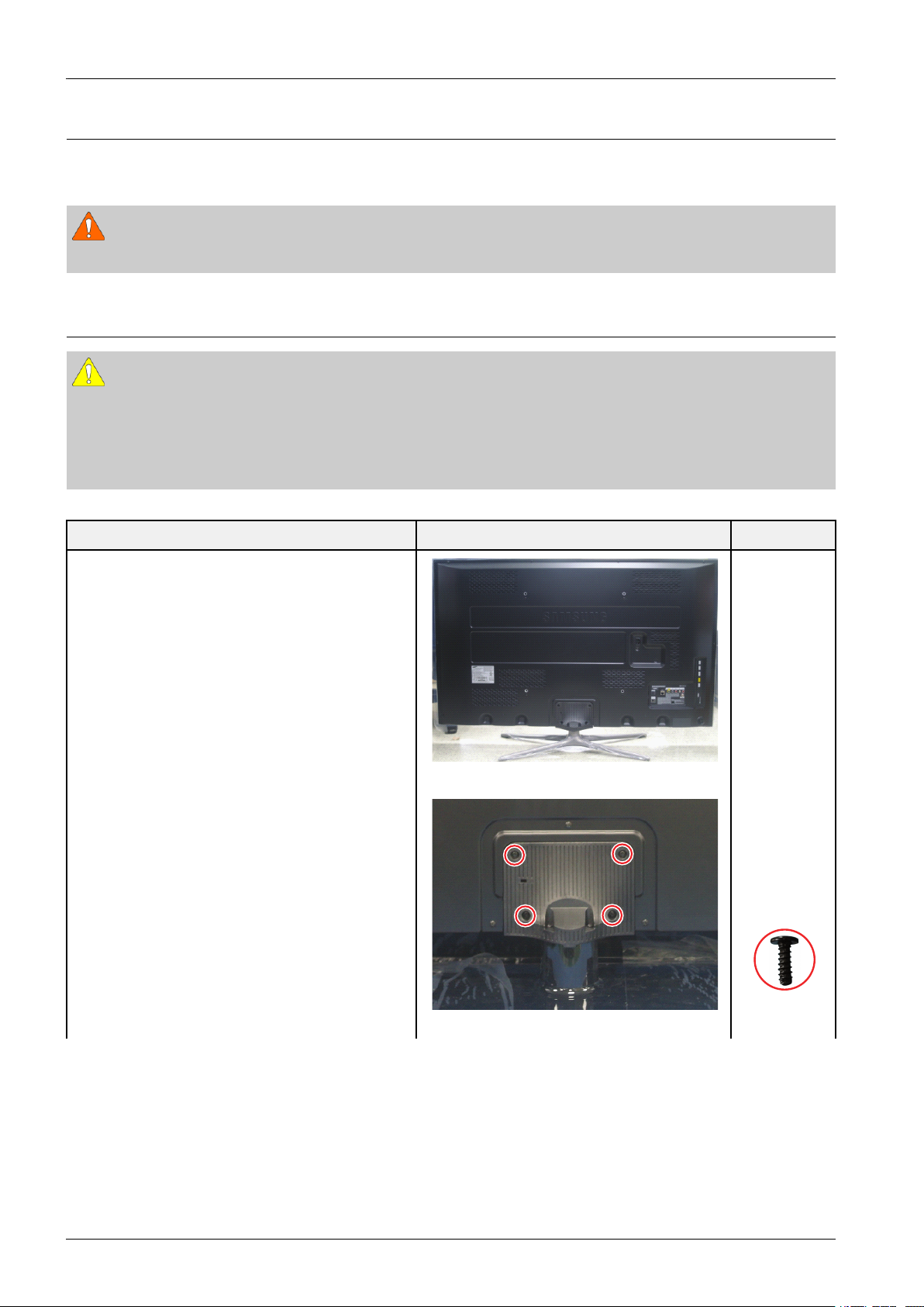
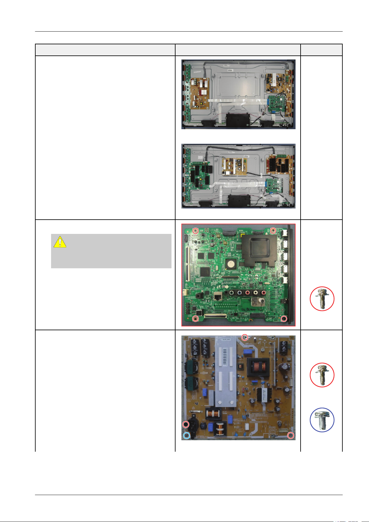
DescriptionDescriptionPhotoScrew
1.Placemonitorfacedownoncushionedtable.
RemovescrewsfromtheStand.
Removestand.
<51">
<51">
3-1Copyright©1995-2013SAMSUNG.Allrightsreserved.
6003–001782
M4*L12
Page 13
3.DisassemblyandReassembly
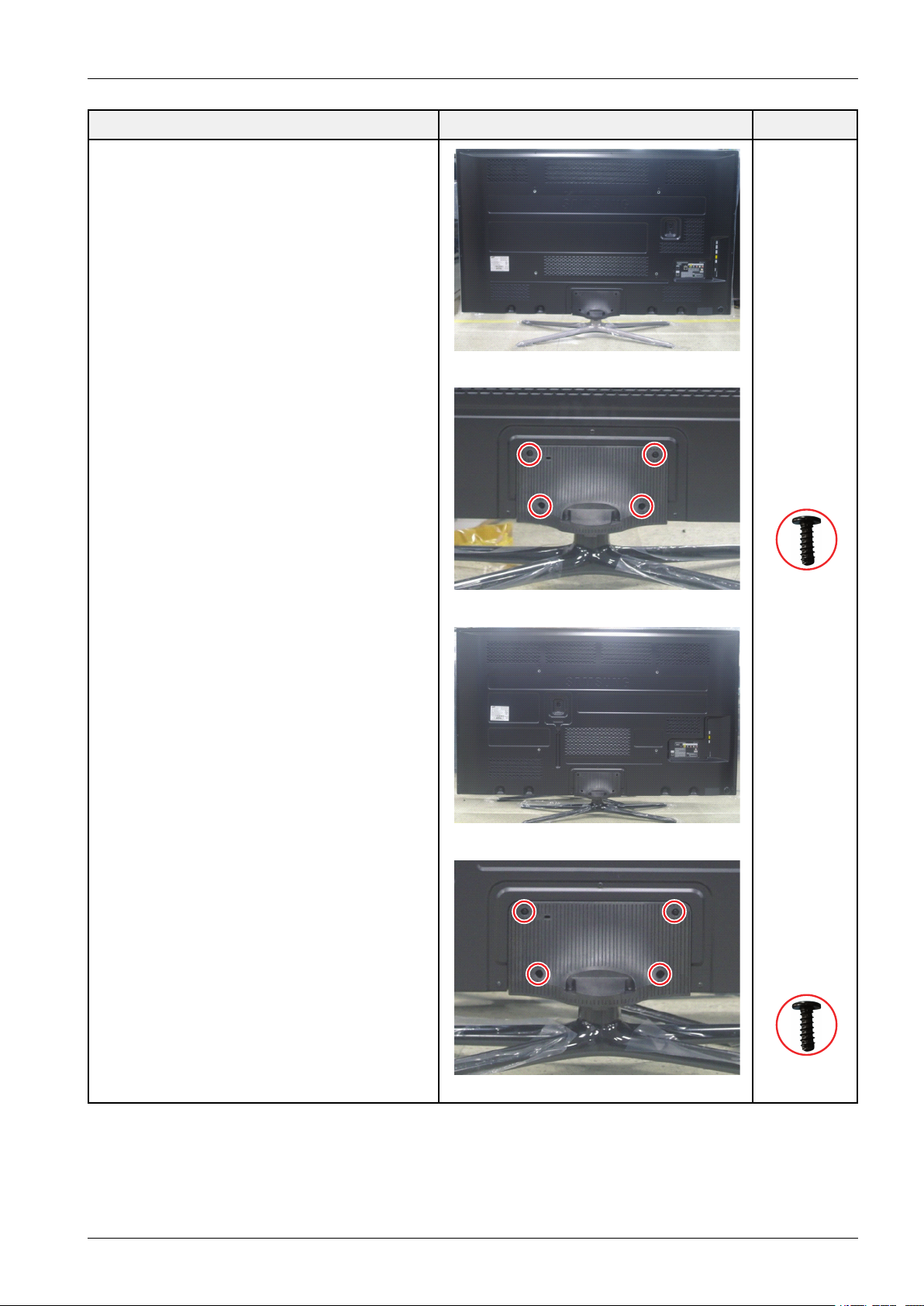
DescriptionDescriptionPhotoScrew
<60">
6003–001782
<60">
M4*L12
<64">
6003–001782
<64">
Copyright©1995-2013SAMSUNG.Allrightsreserved.3-2
M4*L12
Page 14
3.DisassemblyandReassembly
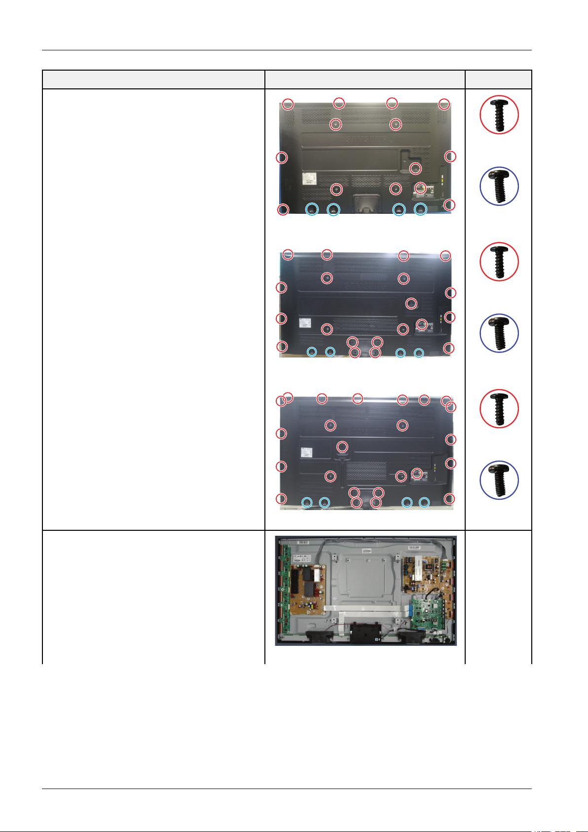
DescriptionDescriptionPhotoScrew
2.Removethescrewsofrear-cover.
6003–001782
M4*L12
6003–000337
<51">
M4*L10
6003–001782
M4*L12
3.Liftupandremovetherear-cover.
<60">
6003–000337
M4*L10
6003–001782
M4*L12
6003–000337
<64">
M4*L10
<51">
3-3Copyright©1995-2013SAMSUNG.Allrightsreserved.
Page 15
3.DisassemblyandReassembly
DescriptionDescriptionPhotoScrew
<60">
4.Removethescrewsofmainboard.
CAUTION
Disconnectallconnectorspriortoremoving
boards.
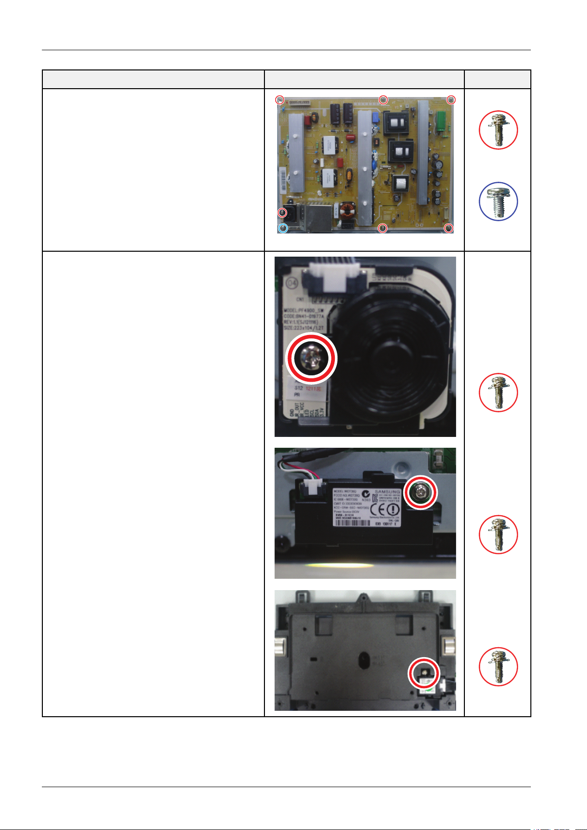
5.RemovethescrewsofSMPS.
RemovetheSMPS.
<64">
6001–002606
M3*L10
6001–002606
M3*L10
6003–001439
<51"><60">
Copyright©1995-2013SAMSUNG.Allrightsreserved.3-4
M3*L10
Page 16
3.DisassemblyandReassembly
6.RemovethescrewofFunction.
RemovetheFunction.
DescriptionDescriptionPhotoScrew
6001–002606
M3*L10
6003–001439
<64">
M3*L10
RemovethescrewofWI-FImodule.
RemovetheWI-FImodule.
WI-FIcode:BN59-01161A
Removethescrewofblue-toothmodule.
Removetheblue-toothmodule.
Blue-toothcode:BN96-25376A
6001–002606
M3*L10
6001–002606
M3*L10
6001–002606
M3*L10
3-5Copyright©1995-2013SAMSUNG.Allrightsreserved.
Page 17
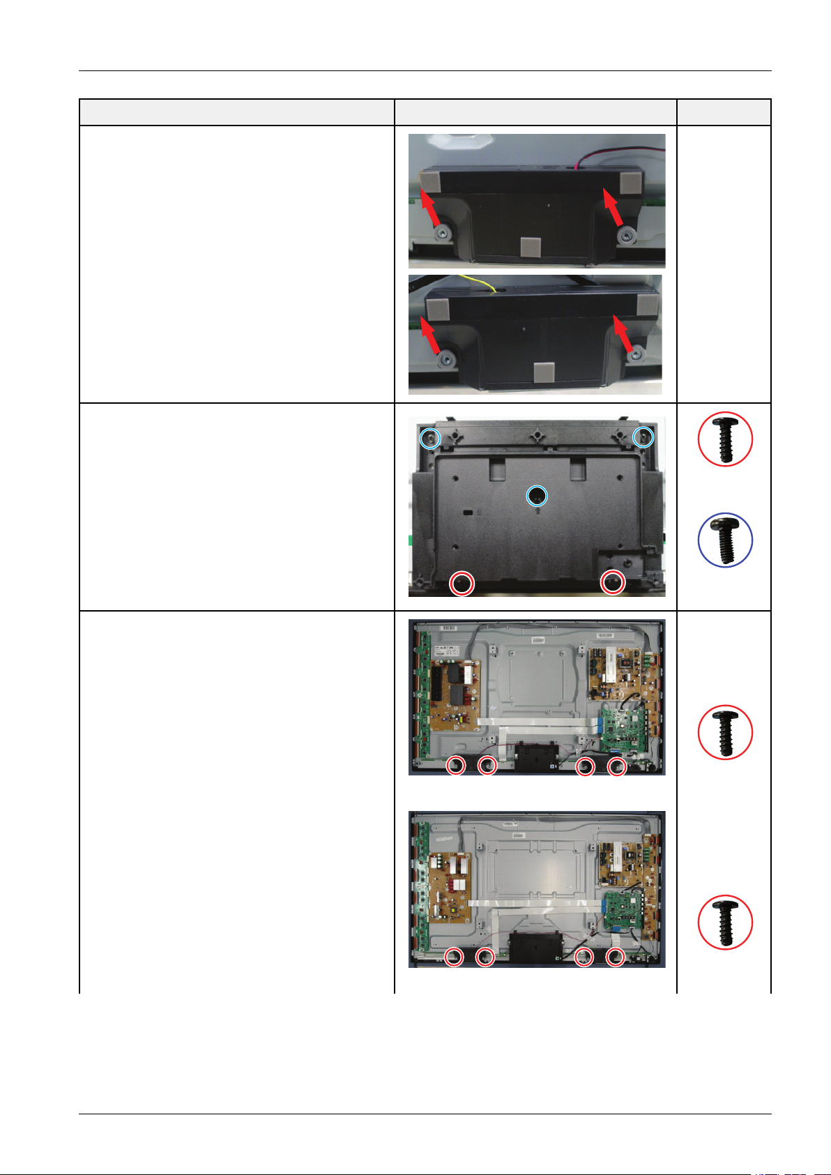
7.Removethespeakers.(R/L)
RemovethescrewofCoverbottom.
3.DisassemblyandReassembly
DescriptionDescriptionPhotoScrew
8.Removethescrewsofthefront-cover.
6003–001782
M4*L12
6003–000337
M4*L10
6003–001782
<51">
M4*L12
6003–001782
<60">
Copyright©1995-2013SAMSUNG.Allrightsreserved.3-6
M4*L12
Page 18
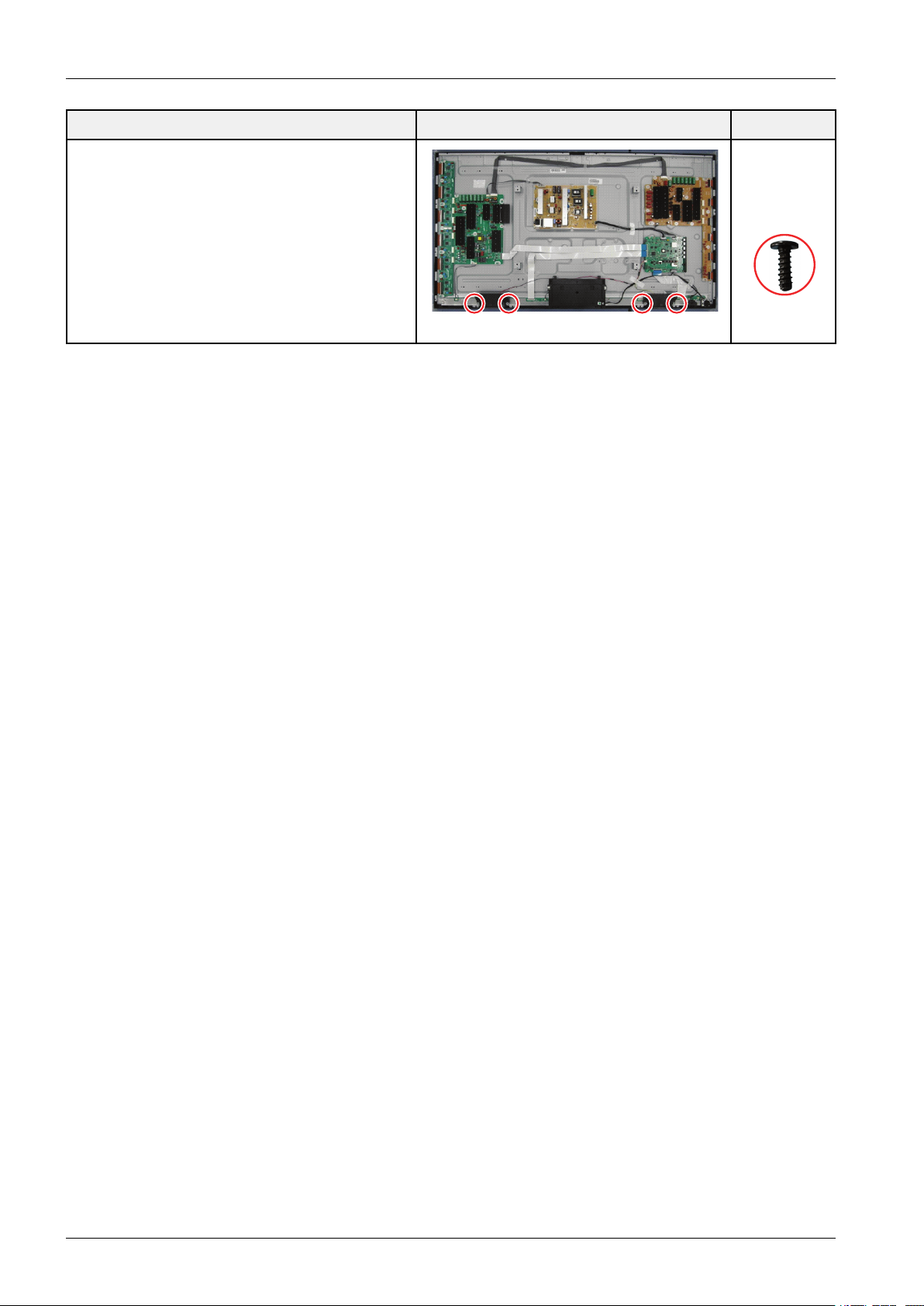
3.DisassemblyandReassembly
DescriptionDescriptionPhotoScrew
6003–001782
<64">
M4*L12
3-7Copyright©1995-2013SAMSUNG.Allrightsreserved.
Page 19
4.Troubleshooting
4.1.FirstChecklistforTroubleshooting
1)Checkthevariouscableconnectionsrst.
•Checktoseeifthereisaburntordamagedcable.
•Checktoseeifthereisadisconnectedorloosecableconnection.
•Checktoseeifthecablesareconnectedaccordingtotheconnectiondiagram.
2)CheckthepowerinputtotheMainBoard.
3)HowtodistinguishiftheproblemiscausedbyMainboardorLogicBoard.
•NoVideo:IftheproblemisNoVideobutLogicBoardisonandIndicationLEDisblinkingrepeatedlyand
fasterthannormalbooting,replacetheLogicboard.
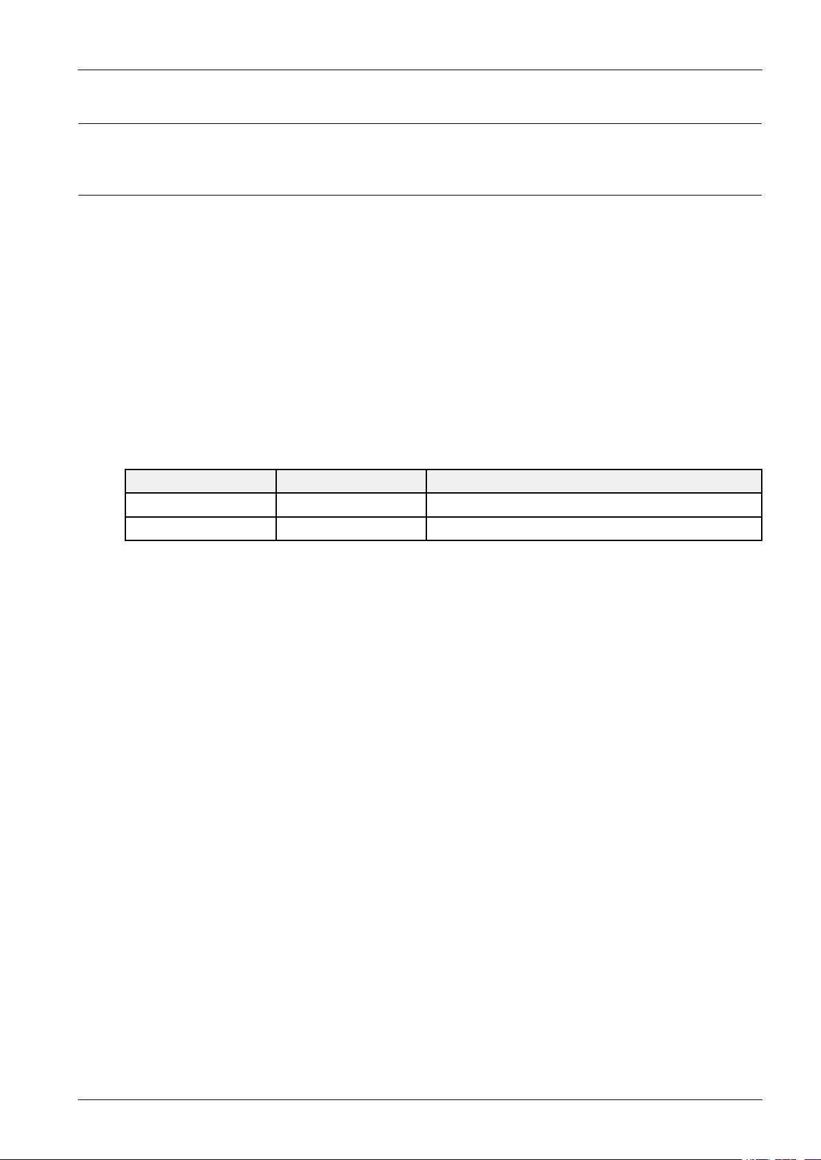
•DistortedPicture:Checktheinnerpatterns.
4.Troubleshooting
InnerpatternPictureProblem
OKNGMainBoard
NGNGMain/LogicBoardorPanel.
•HowtocheckLogictestpattern?
a.EnteringFactorymode
b.MovetoSVCmenu
c.MovetoTestPattern
d.Checktestpatterns.
Copyright©1995-2013SAMSUNG.Allrightsreserved.4-1
Page 20
4.Troubleshooting
Fuse
CN801
CN201
Fuse
CN801
CN201_CO
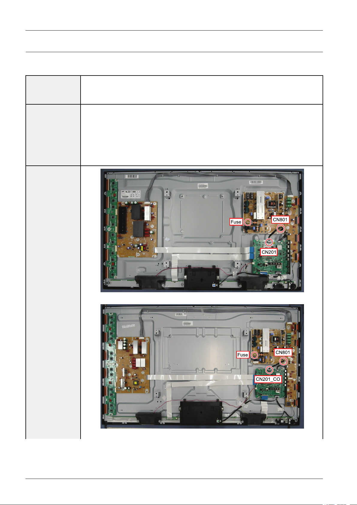
4.2.CheckpointsbyErrorMode
■NoPower
•TheLEDsonthefrontpaneldonotworkwhenconnectingthepowercord.
Symptom
MajorChecklist
•TheSMPSrelaydoesnotworkwhenconnectingthepowercord.
•Theunitappearstobedead.
TheSMPSrelayortheLEDsonthefrontpaneldoesnotworkwhenconnectingthepowercordif
thecablesareimproperlyconnectedortheMainBoardorSMPSisnotfunctioning.Inthiscase,
checkthefollowing:
•Checktheinternalcableconnectionstatusinsidetheunit.
•Checkthefusesofeachpart.
•ChecktheoutputvoltagesoftheSMPS.
•ReplacetheMainBoard.
<51"PDP>
<60"PDP>
Diagnostics
4-2Copyright©1995-2013SAMSUNG.Allrightsreserved.
Page 21

4.Troubleshooting
Fuse
CN801
CN201
Yes
Yes
Yes
Yes
P owe r ind ica to r LED is o n?
Che ck AC powe r con nection .
Re p lace the Main Boa rd .
Co nn e c t th e c a ble b e twe e n
CN8 01 a nd C N10 1 con ne ctor.
Are the S MPS CN40 07 a nd Ma in
CN2 01 c on n e cte d?
Re p lace Fus e . (F801 S )
Is th e Fus e (F801S ) of the SMPS Po we r
Inpu t P a rt Ope n?
Re p lace the SMPS .
S MPS CN80 1
P IN2 : S TB 5V
PIN1 _P S O N : Ch e ck to s e e if it is 0 V
No
No
No
No
<64"PDP>
CAUTION
MakesuretodisconnectthepowerbeforeworkingontheSMPSboard.
Copyright©1995-2013SAMSUNG.Allrightsreserved.4-3
Page 22

4.Troubleshooting
Module FFC Cable
Module FFC Cable
■NoVideo
Symptom•Audioisnormalbutnopictureisdisplayedonthescreen.
•TheoutputvoltageoftheMainSMPS.
MajorChecklist
•ThismayhappenwhentheLVDScableconnectingtheMainBoardandthePanelis
disconnected.
Diagnostics
<51"PDP>
<60"PDP>
4-4Copyright©1995-2013SAMSUNG.Allrightsreserved.
Page 23

4.Troubleshooting
Module FFC Cable
Check the LED
Operation.
Ye s
Ye s
Ye s
Re p lace the Main Boa rd .
Che ck / Re pla ce the FFC Ca ble.
Che ck the FFC C a ble
Is it con necte d co rre ctly?
Re p lace the S MPS .
Che ck All output voltag e s o n S MPS.
Are all volta ge ne rma l?
Che ck the LED ope ra tion of Log ic Boa rd
whitch is norma lly ope ra ting?
(Norma l : Blink on ce a s e con d)
No
No
No
Che ck / Re pla ce the X/Y Ma in or
Logic Boa rd .
<64"PDP>
Copyright©1995-2013SAMSUNG.Allrightsreserved.4-5
Page 24

4.Troubleshooting
CAUTION
MakesuretodisconnectthepowerbeforeworkingontheSMPSboard.
4-6Copyright©1995-2013SAMSUNG.Allrightsreserved.
Page 25

■NoSound
Speaker
Speaker Cable
CN801
Speaker
Speaker Cable
CN801
Symptom•Videoisnormalbutthereisnosound.
•Whenthespeakerconnectorsaredisconnectedordamaged.
MajorChecklist
•WhenthesoundprocessingpartoftheMainBoardisnotfunctioning.
•Speakerdefect.
•SMPSnotsupplyingvoltagetothemainboard.
4.Troubleshooting
Diagnostics
<51"60"PDP>
<64"PDP>
Copyright©1995-2013SAMSUNG.Allrightsreserved.4-7
Page 26

4.Troubleshooting
Yes
Yes
Yes
Re p lace the Spe ake r.
Re p lace the SMPS .
Is th e outpu t voltag e o f S MPS norm a l?
(CN801 P IN 7 : 15 V)
Re p lace the Main boa rd.
(1)
Is the spe ake r outpu t te rm ina l of
the Main boa rd no rmal?
Conn e ct the ca ble p rop e rly or
repla ce the ca ble , if ne cess a ry.
Is the ca b le co nne c tion be twee n
Main boa rd a nd th e s pea ke r
prope rly co nn e cte d?
No
No
No
Sound Output S ha pe
(1)
CAUTION
MakesuretodisconnectthepowerbeforeworkingontheIPboard.
4-8Copyright©1995-2013SAMSUNG.Allrightsreserved.
Page 27

4.2.1.ExampleofTroubleShooting
SymptomRelatedImageCausesandCountermeasures
4.Troubleshooting
Ablankverticalcell(block)
appearsonthescreen.
Agreenscreenappearswhen
theTVisturnedon.
TheOSDboxappearsbutthere
isnotext.
•Addressbufferdefect
•Replacethecorrespondingupper/lower
buffers.
•COFdefect(burnt)
•Replacethemodule.
•TheScaleisnotresecting.
•ReplacetheMainboard.
•Incorrectprogramversion.
•Checktheversionofeachprogram.
•ReplacetheMainboard.
Ablankupper(orlower)block
appearsonthescreen.
Eitherthemainorsubpicture
doesnotappear.
•Upper/LowerYBufferdefect
•Replacethecorrespondingupper/
lowerbuffers.
•ReplacetheMainboard.
Copyright©1995-2013SAMSUNG.Allrightsreserved.4-9
Page 28

4.Troubleshooting
SymptomRelatedImageCausesandCountermeasures
Averticalgreenlineappearson
thescreen.
•TheSMPSvoltageisincorrect.
•AdjusttheSMPSvoltageaccording
tothevoltageprintedonthemodule
label.
Dimscreen(blurredinred)•X-Mainboarddefect
•ReplacetheX-Mainboard.
Ablankscreenappears.•ReplacetheY -Mainboard.
4-10Copyright©1995-2013SAMSUNG.Allrightsreserved.
Page 29

4.2.2.OperatingLogicLED
■Normal
•LEDblinktimeisonceper0.5s
■Abnormal
•LEDBlinkinterveris0.3sandOfftime4s
4.Troubleshooting
Copyright©1995-2013SAMSUNG.Allrightsreserved.4-11
Page 30

4.Troubleshooting
■PDPModuleAction
4-12Copyright©1995-2013SAMSUNG.Allrightsreserved.
Page 31

4.3.FactoryModeAdjustments
4.3.1.DetailFactoryOption
•Ifyoureplacethemainboardwithnewone,pleasechangethefactoryoptionaswell.
•Theoptionsyoumustchangeare“T ype”.
ModelNamePN51F5500PN60F5500PN64F5500
VendorSDISDISDI
CodeBN96-25240ABN96-25241ABN96-25242A Panel
Spec
SMPSCodeBN44-00600ABN94-06194BBN44-00618A
ChassisAss'yBN94-06194ABN91-10288BBN94-06194C
MainAssy
PBAAss'ycodeBN97-07107WBN97-07107XBN97-07107Y
4.Troubleshooting
Factory
0FactoryReset-
1T ype51FFHcD60FFHcD64FFHcD
2LocalsetUS
3SWModelPF5500
4BOMModel-
5TunerSI_ADI
6ChtableNONE
7Country-
8FrontColorP-W-D-55
Copyright©1995-2013SAMSUNG.Allrightsreserved.4-13
Page 32

4.Troubleshooting
¾¾ ÆÆ ´´ ÁÁoo
¾¾ ÆÆ ´´ ÁÁoo
¤¤ ££ oo
INFO
Factory
4.3.2.EnteringFactoryMode
■Toenter‘ServiceMode’Presstheremote-controlkeysinthissequence.
•IfyoudonothaveFactoryremote-control.
•IfyouhaveFactoryremote-control.
4-14Copyright©1995-2013SAMSUNG.Allrightsreserved.
Page 33

•Ifyoudon’thaveFactoryremotecontrol,can’tcontrolsomemenu.
Option
Control
Debug
SVC
ADC/WB
Advanced
T-MST12AKUC-xxxx
T-MST12AKUS-xxxx
BTV ersion:xxxx
CameraV ersion:xxxx
E-Manual:xxxx
EDIDSUCCESS
CALIB:A V/COMP/PC/HDMI/
Option:xxxx,US,6400,NONE
USBRS232C:OFF
4.Troubleshooting
SDAL-X12-MAIN-xxxx-xxxx
RFS:"X120071"KER/201x-xx-xx
KERNEL:8.0837,D/Onboot:xxxx.x
BackendIC[x],DataV er:xxxx
TCONV ersion:xxxx
DTP-DTVTD-xxxx
Model:PN51F5500
WiredMACSUCCESS
WirelessMACSUCCESS
DRM:CrtO,NfO,WvO,HcO,DcO,MxO,MIO
FactoryDataV er:97
EERCV ersion:51
DTP-BP-HAL-3183
DTP-AP-CNC-3151
DTP-AP-MM-3145
DTP-AP-WP-3148
DTP-BP-MW-3156
DTP-BP-APP-3156
POP-FLA-13-TEMP
Dateofpurchase:mm/dd/yyyy
Copyright©1995-2013SAMSUNG.Allrightsreserved.4-15
Page 34

4.Troubleshooting
4.3.3.FactoryData
■Option
FactoryMenuNameDataRemark
FactoryReset
Type51FFHcD/60FFHcD/64FFHcD
LocalSetUS
SWModelPF5500
BOMModel
TUNERSI_ADI
ChTableNONE
FrontColorP-W-D-55 MRTOption
LVDSFORMA TVESA
Language_ArabicUS
RegionUSA
PnPLanguageENG_US
WIFIREGIONS
OTNSupportON
OTASupportOFF
TTXOFF
ChinaHDOFF
NTConversionOFF
NumofDTV1
NumofA V1
NumofCOMP1
NumofHDMI3
NumofSCART0
NumofUSBPort2
NumofHeadPhone0
NumofRVU1
NumofDisplay2
NumofIPTV0
NumofRUI0
NumofPVRRECORD0
TOOLSSupport40
LNASupportOFF
24Px4SupportOFF
BDWiseSupportON
DataServiceSupportOFF
PVRSupportOFF
CISupportOFF
4-16Copyright©1995-2013SAMSUNG.Allrightsreserved.
Page 35

FactoryMenuNameDataRemark
LEDMotionPlusSupportON
NaturalModeSupportON
RelaxModeSupportOFF
HDMI/DVISEL3
SelectLCD/PDPPDP
WallMountOFF
HVFlipOFF
LightEffectOFF
e-PopDefault1
CAMERASupportOFF
NETWORKSupport3
EcoSensorSupportON
3DSupportON
BTSupportON
4.Troubleshooting
BTADDRESS
Engineer
AutoPowerMEMORY
Option
TypeOfP ANELKEYNone
5W ayFunctionKeyL_BACK
ContentsBarOFF
CableModulationQAM
Standbyledon/offOFF
RecognitionSupport
IFAGC0
DAGC0
PHBW0
FQBW0
PHRA TE0
PDEN0
PEQInx0
WFScale
WFType0
NuofNetworkStream1
DPVSize0
BackendDevicePARMA
BT_AUDIO_ON_OFFOFF
Cong_A V_P A TH
ECOStandbyOFF
FastLogoDelay0
NumofPANELKEY6
Copyright©1995-2013SAMSUNG.Allrightsreserved.4-17
Page 36

4.Troubleshooting
■Control
MenuItemDataRemark
EDIDEDIDON/OFFOFF
EDIDWRITEALL...
EDIDWRITEHDMI...
EDIDV er...
EDIDPort
SubOptionRS-232JackUART
WatchdogOFF
Checksum0x0000
FastBootinProductionOFF
USBSerialOFF
EepromReset
ECOICTYPENONE
InfoLinkServerT ypedevelopment
InfoLinkCountryNone
TTXGroup
VisualTest
MediaPlayDB
OPTION_SWU
OTNServerTypeoperating
OTNT estServerOFF
SWUReset
SWUDurationOFF
SWUFailTestOFF
OPTION_NUM
NumofATV1
NumofSVIDEO0
NumofPC0
NumofDVI0
NumofOPTICALLink1
NumofMEDIA1
NumofTuner1
NumofISP1
RFRemoconSupportOFF
CDDmode
DPMSSupportOFF
NumofIPTVCIP0
NumofCI0
NumofDECODER0
T-CONDevice
4-18Copyright©1995-2013SAMSUNG.Allrightsreserved.
Page 37

MenuItemDataRemark
BOARDCONTROLOFF
HPLINELineOut
RM
ServerTypeOperating
RTSModeOFF
PSA
FKPDownload10
FKPDownload20
LMKthreshold3
Lowthreshold10
Highthreshold15
CSBON
CLBON
PDPOptionPixelShiftTestOFF
4.Troubleshooting
LogicSW0
PanelT emperature0
LOGICW aveformDay0
LogicCheckSum0
MRT0
SAPCTimer
APCSpeed
HotelOptionHospitalityModeOFF
PowerOn...
MenuOSD...
Operation...
MusicMode...
ExternalSource...
EcoSolution...
Cloning...
ShopOptionShopModeOFF
ExhibitionModeOFF
3DCubeOFF
AsiaOption
UnbalanceOFF
AFLeveladjust3
TXPowerLevel0
MonoLastMemoryOFF
HShakingOFF
SoundCarrier_MuteOFF
HighDeviOFF
SpeakerDelayNormal0x96h
Copyright©1995-2013SAMSUNG.Allrightsreserved.4-19
Page 38

4.Troubleshooting
MenuItemDataRemark
SPDIFPCMGain-9dB
FMMPrescale0x30h
FMPrescale0z44h
AMPrescale0x32h
NICAMPrescale0x48h
BTSCMonoPrescale0x19h
BTSCstereoPrescale0x2Fh
BTSCSAPPrescale0x2Bh
A2IdentHighTHID36
A2IdentLowTHID9
PilotLevelHighThld0x28h
PilotLevelLowThld0x10h
Carrier2AmpHighTHID4
Carrier2AmpLowTHID3
Carrier2SNRHighTHR16
Carrier2SNRLowTHR80
SigErrorOn35
SigErrorOff41
AmpModelTAS5745
AmpV olume0xcbh
AmpScale0x2Fh
AmpCheckSum
WooferType0
WooferScale0x8ah
WooferCheckSumNONE
WooferLocalEQ
Checksum
SpeakerEQON
PEQTestReady
LocalSpeakerEQ0
LocalEQChecksum0
Speakercut-offFerq4
0
Audio-IPTest
SRSTuningParm0
TruBass-CheckSum0
MicScale0
SubwooferSupport0
IndiaSoundOFF
AudioDockBTdelay50
WallFilterType0
WiselinkDelayMenu70
4-20Copyright©1995-2013SAMSUNG.Allrightsreserved.
Page 39

4.Troubleshooting
■Debug
MenuItemDataRemark
SpreadSpectrum
LVDSSpreadON
DDRSpread1.0%Spectrum
Period30K
Amplitude1
HDSSCON/OffON
HDSSCValue1
LVDSSSCON/OffON
LVDSSSCV alue0
DDRSSCON/OffON
DDRSSCValue1
FRCL VDSSSC
ON/OFF
FRCL VDSSSC
MRR
FRCL VDSSSC
MFR
FRCL VDSSSC
Period
FRCL VDSSSC
Modulation
ON
10
1
1
1
FRCDDRSSC
ON/OFF
FRCDDRSSC
MRR
FRCDDRSSC
MFR
FRCDDRSSC
Period
FRCDDRSSC
Modulation
DDRMargin
NDADJSupportON
MICOMPOWER
OFF
A
CTRL_OFFSET_0_3
A
CTRL_OFFSET_D
B
CTRL_OFFSET_0_3
B
CTRL_OFFSET_D
ON
15
1
1
1
ON
1.0%Spectrum
30K
1
1
RFMuteTimeON
Copyright©1995-2013SAMSUNG.Allrightsreserved.4-21
Page 40

4.Troubleshooting
MenuItemDataRemark
CI+1.30
FRC
FRCFDISPLA Y
ON
1
ON/OFF
3DFDISPLA Y
ON
ON/OFF
PCModeON/OFF10
TunerMargin1
MPEGMargin1
H.264Margin1
CAMW aitTimeON
TSClockdeldy15
TCON_TEMP
1
READ
TEMPLAST1
DCCVERSION1
DCCCHKSEL0
DCCCHECK
0x0
LOCAL
DCCCHECK
0x0
TOTAL
MulitACC
0
Checksum
IICBusstopOFF
TunerStatus
DVBSNR
BER
SignalStrength
Bandwidth
Frequency
LNAStatus
FFT
Modulation
CodeRate
GI
HierModulation
Frequencyoffset
Timingoffset
AGC
UCB
PLLType
DEMODT ype
TPSLock
4-22Copyright©1995-2013SAMSUNG.Allrightsreserved.
Page 41

MenuItemDataRemark
RSLock
SSI
SQI
FirmwareV ersion
ISDB-TFFTSize_1
GuardInterval_1
Freq.Offset_1
SNR_1
IFAGC_1
TMCCLock_1
TSPacker_1
MasterLock_1
A_Modulation_1
A_CodeRate_1
4.Troubleshooting
A_Timer
InterLeave_1
A_Segments
Num_1
A_BER_1
B_Modulation_1
B_CodeRate_1
B_Timer
InterLeave_1
B_Segments
Num_1
B_BER_1
C_Modulation_1
C_CodeRate_1
C_Timer
InterLeave_1
C_Segments
Num_1
C_BER_1
Copyright©1995-2013SAMSUNG.Allrightsreserved.4-23
Page 42

4.Troubleshooting
■SVC
MenuItemDataRemark
TestPattern
PatternSelOFF
LogicPatternSel
LogicLevelSel
FRCPreT est
Pattern
FRCPostTest
Pattern
FRC3DFdisplayOFF
FRC3DPCModeOFF
SOCTCONTest
Pattern
SOCTCONPattern
Level
SOCTCONFRC
Pattern
HDMIWBPatternOFF
HDMIPatternSel0
ParmaPreT est
Pattern
0
0
0
##
0
0
ParmaPostTest
Pattern
PanelDisplayTime0Hr
SVCInfo0
DeleteS/N0
Upgrade
T-CONUsb
Download
T-CONCheckSum...
LogicUsbD/LFailute
SUBMICOM
UPGRADE
BTUPGRADE
BTFREEP AIRINGON
FunctionUpgradeFailute
FRC3DFW
Upgrade
CameraUpgrade
MicUpgrade
CPLDUSB
Download
0
...
Ready
JPMICOM
UPGRADE
DPMICOM
UPGRADE
4-24Copyright©1995-2013SAMSUNG.Allrightsreserved.
Failute
Failute
Page 43

MenuItemDataRemark
JumpUpgradeFailute
SmartHubReset0
4.Troubleshooting
ERCount
LOG(ViewLog)
SelfDiagnosis
WDCount0
ARCount0
WIFIERCount0
BTERCount0
HDMIErrCnt0
CameraERCount0
SelectLogTypeNVRAM
LogView0
DeleteLog
DebugLogDown
EmergencyLog
Copy
LoopBack
LANTest
A VAudioTest
DVINAudioTest
CVBSTest
COMPTest
USBHUBTest
HDMITest
SCARTAudioT est
SCARTCVBSTest
SCARTRGBT est
CPU
DDR
FLASH
EEPROM
SoundAMP
HDMISwitchIC
USBHUBIC
WIFI
LVDS
T-CON/FRC
PCBTest
MOIP
AppSelfTest
DeviceselfTest
V oltage
Copyright©1995-2013SAMSUNG.Allrightsreserved.4-25
Page 44

4.Troubleshooting
MenuItemDataRemark
EcoSensor
BT
EXTSound
Inspection
WooferSound
Inspection
ATVCHInspection
DTVCHInspection
SatelliteCH
Inspection
IPERFStopped
OPTIONHDMI
Expert
DVBCI
CALDataBackup
CALDataRestore
NONE
4-26Copyright©1995-2013SAMSUNG.Allrightsreserved.
Page 45

4.Troubleshooting
■ADC/WB
MenuItemDataRemark
ADC
ADCResult
WhiteBalance
A VCalibrationSuccess
CompCalibraionSuccess
PCCalibrationSuccess
HDMICalibrationSuccess
1st_Y_GH258
1st_Y_GL128
1st_Cb_BH
1st_Cb_BL
1st_Cr_RH
1st_Cr_RL
2nd_R_L132
2nd_G_L132
2nd_B_L132
2nd_R_H70
2nd_G_H70
2nd_B_H70
R-Offset128
G-Offset128
B-Offset128
R-Gain128
G-Gain128
B-Gain128
WB_W2_R_Offset128
WB_W2_B_Offset128
WB_W2_R_Gain164
WB_W2_B_Gain63
WB_N_R_Offset128
WB_N_B_Offset128
WB_N_R_Gain151
WB_N_B_Gain108
MGA
MGAOn/OffOFF
R1_Gain
B1_Gain
G1_Gain
R2_Gain
B2_Gain
G2_Gain
R3_Gain
B3_Gain
Copyright©1995-2013SAMSUNG.Allrightsreserved.4-27
Page 46

4.Troubleshooting
MenuItemDataRemark
G3_Gain
R4_Gain
B4_Gain
G4_Gain
R5_Gain
B5_Gain
G5_Gain
R6_Gain
B6_Gain
G6_Gain
R7_Gain
B7_Gain
G7_Gain
R8_Gain
B8_Gain
G8_Gain
R9_Gain
B9_Gain
G9_Gain
R10_Gain
B10_Gain
G10_Gain
4-28Copyright©1995-2013SAMSUNG.Allrightsreserved.
Page 47

4.4.WhiteBalance–Calibration
4.Troubleshooting
Copyright©1995-2013SAMSUNG.Allrightsreserved.4-29
Page 48

4.Troubleshooting
ADC / WB
AV Ca libra tion
Comp Calibration
HDMI Calibration
4.4.1.WhiteBalance-Calibration
•Factory
4.4.2.ServiceAdjustment
•YoumustperformCalibrationintheLatticePatternbeforeadjustingtheWhiteBalance.
■ColorCalibration
•Adjustspec.
1)Source:HDMI
2)SettingMode:1280*720@60Hz
3)Pattern:Pattern#24(ChessPattern)
4)UseEquipment:CA210&MasterMSPG925Generator
UseotherequipmentonlyaftercomparingTheresultwiththatofTheMasterequipment.
InputmodeCalibrationPattern
CVBSIN(Model_#1)PerforminNTSC/P ALB&WPattern#24Lattice
ComponentIN(Model_#6)Performin720pB&WPattern#24Lattice
PCAnalogIN(Model_#21)PerforminVESAXGA(1024x768)B&WPattern#24Lattice
HDMIINPerformin720pB&WPattern#24Lattice
4-30Copyright©1995-2013SAMSUNG.Allrightsreserved.
Page 49

•MethodofColorCalibration(A V)
1)ApplytheNTSC/PALLattice(N0.3)patternsignaltotheA VIN1port.
2)PresstheSourcekeytoswitchto“A V1”mode.
3)EnterServicemode.
4)Selectthe“ADC”menu.
5)Selectthe“AVCalibration”menu.
4.Troubleshooting
6)In“AVCalibrationOff”status,pressthe“
7)WhenCalibrationiscomplete,itreturnstothehigh-levelmenu.
8)Y oucanseethechangeofthe“AVCalibration”statusfromFailuretoSuccess.
”keytoperformCalibration.
•MethodofColorCalibration(Component)
1)Applythe720pLattice(N0.6)patternsignaltotheComponentIN1port.
2)PresstheSourcekeytoswitchto“Component1”mode.
3)EnterServicemode.
4)Selectthe“ADC”menu.
5)Selectthe“CompCalibration”menu.
6)In“CompCalibrationOff”status,pressthe“
7)WhenCalibrationiscomplete,itreturnstothehigh-levelmenu.
8)Y oucanseethechangeofthe“CompCalibration”statusfromFailuretoSuccess.
”keytoperformCalibration.
•MethodofColorCalibration(HDMI)
1)Applythe720pLattice(N0.6)patternsignaltotheHDMI1/DVIINport.
2)PresstheSourcekeytoswitchto“HDMI1”mode.
3)EnterServicemode.
4)Selectthe“ADC”menu.
5)Selectthe“HDMICalibration”menu.
6)In“HDMICalibrationOff”status,pressthe“
7)WhenCalibrationiscomplete,itreturnstothehigh-levelmenu.
8)Y oucanseethechangeofthe“HDMICalibration”statusfromFailuretoSuccess.
”keytoperformCalibration.
Copyright©1995-2013SAMSUNG.Allrightsreserved.4-31
Page 50

4.Troubleshooting
ADC / WB - White Balance
Factory (Low light) (High light)
Sub Bright
R offset
G offset
B offset
Sub Contrast
R gain
G gain
B gain
4.4.3.WhiteBalance-Adjustment
4-32Copyright©1995-2013SAMSUNG.Allrightsreserved.
Page 51

4.5.SoftwareUpgrade
SamsungmayofferupgradesfortheTV’srmwareinthefuture.
TheseupgradescanbeperformedviatheTVwhenitisconnectedtotheInternet,orbydownloadingthenewrmware
fromsamsung.comtoaUSBmemorydevice.
•AlternativeSoftware(Backup)showsThepreviousversionthatwillbereplaced.
•Softwareisrepresentedas‘Y ear/Month/Day_Version’.
Themorerecentthedate,thenewerthesoftwareversion.
Installingthelatestversionisrecommended.
■ByUSB
4.Troubleshooting
InsertaUSBdrivecontainingthermwareupgradedownloadedfromsamsung.comintotheTV.
PleasebecarefultonotdisconnectthepowerorremovetheUSBdrivewhileupgradesarebeingapplied.
TheTVwillturnoffandturnonautomaticallyaftercompletingthermwareupgrade.
Pleasecheckthermwareversionaftertheupgradesarecomplete(thenewversionwillhaveahighernumberthanthe
olderversion).
Whensoftwareisupgraded,videoandaudiosettingsyouhavemadewillreturntotheirdefault(factory)settings.
Werecommendyouwritedownyoursettingssothatyoucaneasilyresetthemaftertheupgrade.
■ByOnline
UpgradesthesoftwareusingtheInternet.
•First,congureyournetwork.FordetailedproceduresonusingtheNetworkSetting,refertothe‘SettingtheNetwork’
instructions.
•IfTheinternetconnectiondoesn’toperateproperly,connectioncanbebroken,pleaseretrydownloading.Iftheproblem
stillhappens,downloadbyUSBandupgrade.
■AlternativeSoftware(Backup)
Ifthereisanissuewiththenewrmwareanditisaffectingoperation,youcanchangethesoftwaretothepreviousversion.
•IfSoftwarewaschanged,existingSoftwareisdisplayed.
•youcanchangecurrentSoftwaretoAlternativeSoftwareby‘AlternativeSoftware.
Copyright©1995-2013SAMSUNG.Allrightsreserved.4-33
Page 52

4.Troubleshooting
4.6.RS-232C
1.ToRS232Ccontrol
•Port:COM#(Serial)
•Bitrate:9600(Control)
•DataBit:8bit
•Parity:None
•StopBits:1
•FlowControl:None
2.DescriptionofRS232C
Pin#NameFullName
1CDCarrierDetect
2RxDReceivedData
3TxDTransmittedData
4DTRDataT erminalReady
5GNDSignalGround
6DSRDataSetReady
7R TSRequestToSend
8CTSClearToSend
9RIRingIndicator
4-34Copyright©1995-2013SAMSUNG.Allrightsreserved.
Page 53

4.7.AVcontrolcode
4.Troubleshooting
ControlItemCmd1Cmd2Cmd3Value
General
InputSourceList
Power
V olume
Mute0x020x000x000x00
Ch.
Power0x000x000x000x00
Off0x01
On0x02
Direct0x010x000x00(0~100)
Up0x010x00
Down0x020x00
Direct0x04-
Continuous
TVTV0x0a0x000x000x00
A V
S-Video
Up0x010x00
Down
A V10x010x00
A V20x01
A V30x02
S-Video10x020x00
S-Video20x01
S-Video30x02
0x030x00
0x020x00
Component
PC
HDMI
DVI
Picture
Mode
Dynamic(Entertain)0x0b0x000x000x00
Standard0x01
Movie0x02
Natural0x03
Component10x030x00
Component20x01
Component30x02
PC10x040x00
PC20x01
PC30x02
HDMI10x050x00
HDMI20x01
HDMI30x02
HDMI40x03
DVI10x060x00
DVI20x01
DVI30x02
CAL-NIGHT0x04
CAL-DAY0x05
BDWise0x06
BackLight0~200x010x00(0~20)
Copyright©1995-2013SAMSUNG.Allrightsreserved.4-35
Page 54

4.Troubleshooting
ControlItemCmd1Cmd2Cmd3Value
Contrast0~1000x020x00(0~100)
Brightness0~1000x030x00(0~100)
Sharpness0~1000x040x00(0~100)
Color0~100x050x00(0~100)
TintG/R0x060x00(0~100)
AdvancedSettings
BlackTone
Off0x070x000x00
Dark0x01
Darker0x02
Darkest0x03
DynamicContrast
Off0x010x00
Low0x01
Medium0x02
HIgh0x03
ShadowDetail-2~20x02(-2~2)
Gamma-3~30x03(-3~3)
RGBOnlyMode
Off0x050x00
Red0x01
Green0x02
Blue0x03
ColorSpace
Auto0x060x00
Native0x01
Custom0x02
WhiteBalanceR-Offset(LCD)0x07(0~50)
WhiteBalanceG-Offset(LCD)0x08(0~50)
WhiteBalanceB-Offset(LCD)0x09(0~50)
WhiteBalanceR-Gain(LCD)0x0a(0~50)
WhiteBalanceG-Gain(LCD)0x0b(0~50)
WhiteBalanceB-Gain(LCD)0x0c(0~50)
WhiteBalanceReset(LCD)0x0d0x00
FleshTone-15~150x0e(-15~15)
Off0x0f0x00 EdgeEnhancement
On0x01
Off0x100x00 xvYCC
On0x01
Off0x110x00 MotionLighting
On0x01
LEDMotionPlus
Off0x070x00
On(Normal)0x01
Cinema0x02
Ticker0x03
4-36Copyright©1995-2013SAMSUNG.Allrightsreserved.
Page 55

4.Troubleshooting
ControlItemCmd1Cmd2Cmd3Value
PictureOption
ColorTone
Cool0x0a0x000x00
Normal0x01
Warm10x02
Warm20x03
DigitalNoiseFilter
Off0x020x00
Low0x01
Medium0x02
High0x03
Auto0x04
AutoV isualization0x05
MPEGNoiseFilter
Off0x030x00
Low0x01
Medium0x02
High0x03
Auto0x04
Normal0x040x00 HDMIBlackLevel
Low0x01
FilmMode
AutoMotionPlus
ScreenAdjustmentPictureSize
Off0x050x00
Auto10x01
Auto20x02
Off0x060x00
Clear0x01
Standard0x02
Smooth0x03
Custom0x04
Demo0x05
16:90x0b0x0a0x010x00
Zoom10x01
Zoom20x02
WideFit0x03
4:30x04
ScreenFit0x05
SmartViewI0x06
SmartViewII0x07
ResetPictureResetPicture0x0b0x0b0x000x00
3DMode 3D
Off0x0b0x0c0x000x00
2D->3D0x01
SideBySide0x02
TopBottom0x03
LineByLine0x04
Copyright©1995-2013SAMSUNG.Allrightsreserved.4-37
Page 56

4.Troubleshooting
ControlItemCmd1Cmd2Cmd3Value
VerticalLine0x05
CheckerBD0x06
FrameSequence0x07
Off0x010x00 3D->2D
On0x01
3DViewPoint0x02(-5~5)
Depth0x03(1~10)
PictureCorrection0x040x00
3DAutoView
Off0x050x00
MessageNotice0x01
On0x02
Sound
SRS
TheaterSound(Genoa)
SoundMode(X6)
Standard
0x0c0x000x000x00
Music0x01
Movie0x02
ClearV oice0x03
Amplify0x04
Equalizer
Balance0x010x00(0~20)
100hz0x01(0~20)
300hz0x02(0~20)
1khz0x03(0~20)
3khz0x04(0~20)
10khz0x05(0~20)
Reset0x060x00
SRSTruSurround
HD(Genoa)
Off
0x020x000x00
VirtualSurrond(X6)On0x01
SRSTruDialog(Genoa)Off0x030x000x00
DialogClarify(X6)On0x01
PreferredLanguage
English0x040x000x00
Spanish0x01
French0x02
Korean0x03
Japanese0x04
Multi-TrackSound
Mono0x050x000x00
Stereo0x01
SAP0x02
AutoV olume
Off0x060x000x00
Normal0x01
Night0x02
SpeakerSelect
4-38Copyright©1995-2013SAMSUNG.Allrightsreserved.
TVSpeaker0x070x000x00
Page 57

ControlItemCmd1Cmd2Cmd3Value
ExternalSpeaker0x01
Main0x080x000x00 SoundSelect
Sub0x01
SoundResetSoundReset0x090x000x00
KEYKeyGeneration0x0d0x000x00
KeyvalueValue
Up96(0x60)
Down97(0x61)
Left101(0x65)
Right98(0x62)
Menu26(0x1A)
Internet147(0x93)
4.Troubleshooting
referto
thetable
ofbelow
Enter(OK)104(0x68)
EXIT45(0x2D)
Copyright©1995-2013SAMSUNG.Allrightsreserved.4-39
Page 58

4.Troubleshooting
4.8.RearCoverDimension
PF550051"COVER-REARDimension
PF550060"COVER-REARDimension
PF550064"COVER-REARDimension
4-40Copyright©1995-2013SAMSUNG.Allrightsreserved.
Page 59

4.Troubleshooting
ModelInch
Dimension
ABCDEFGH
PF550051”1185.21132.9792.1702.1634.526.341.3671.0
PF550060”1388.31333.5924.1823.3754.427.541.3819.0
PF550064”1478.01424.0967.0870.0804.025.041.3819.0
ModelInch
IJKLMNOP
PF550051”55.7307.2400.0400.0496.9891.536.479.5
PF550060”55.7375.5600.0400.0519.81068.727.5172.4
PF550064”55.7375.5600.0400.0554.41088.843.6176.6
Copyright©1995-2013SAMSUNG.Allrightsreserved.4-41
Page 60

5.WiringDiagram
X- Bu ffe r
Y – DRIVE
CN5 00 0
CN5 00 1
CN5 00 2
CN5 50 1
CN8 01 S
CN5 50 2
CN5 50 3
CN5 50 4
CN5 50 5
CN5 50 6
CN2 50 1
CN201 2_ LO
CN201 3_ LO
CN400 2
CN400 2
CN260 1
CN201
CN801
CN201 0_ LO
CN120 1
Y – Buffer
S MP S
Logic +
Main Bo a rd
E- BUFFE R
CN1
FUNCTION
E- BUFFE R
Spe ake r (L) Spe ake r (R)
CN301
CN500 3
CN400 8
CN500 4
CN400 3
CN400 4
CN 20 11 _LO
CN4 00 7
CN4 00 5
5.WiringDiagram
5.1.OverallWiring
■51"FF
5-1Copyright©1995-2013SAMSUNG.Allrightsreserved.
Page 61

■60"FF
Y
– DRIVE
CN5 00 6
CN5 00 7
CN5 00 3
C
N54 0 4
C
N80 1 S
C
N54 0 5
CN5 40 6
CN5 41 5
CN5 41 4
CN5 41 3
CN5 00 0
CN2 50 1
CN201 2_ LO
CN201 3_ LO
CN400 2
CN400 2
C
N26 0 9
C
N20 1
CN801
CN201 0_ LO
C
N12 0 1
S
MPS
L
ogic +
Main Bo a rd
E
- BUFF ER
C
N1
F
UNCTION
E
- BUFF ER
S
pe ake r (L)
S
pe ake r (R)
CN301
CN500 0
C
N40 0 3
C
N50 0 8
CN500 5
CN500 4
CN500 9
C
N20 11_LO
Y – Buffer
X- Bu ffe r
5.WiringDiagram
Copyright©1995-2013SAMSUNG.Allrightsreserved.5-2
Page 62

5.WiringDiagram
Y – DRIVE
CN5 00 6
CN5 00 7
CN5 00 3
CN5 41 3
CN8 01 S
CN5 41 4
CN5 41 5
CN5 51 3
CN5 51 4
CN5 51 5
CN2 50 1
CN201 2_ LO
CN201 3_ LO
CN401 0
CN400 9
CN270 1
CN201
CN801
CN201 0_LO
CN120 1
Y –
Buffe r
S MP S
Logic +
Main Bo a rd
E- BUFFE R
CN1
FUNCTION
E- BUFFE R
Spe ake r (L) Spe ake r (R)
CN301
CN500 0
CN400 4
CN500 6
CN500 6
CN500 6
CN500 0
CN400 6
CN400 7
CN400 5
CN400 1
CN400 2
CN400 3
CN 20 11 _LO
CN802 _64
X – DRIVE
■64"FF
NOTE
Thecodenumberofcable(Lead-connector)canbechanged,see“ExplodedViewsandPartsList”.
5-3Copyright©1995-2013SAMSUNG.Allrightsreserved.
Page 63

5.WiringDiagram
■51"Cable(Lead-connector)
UsePOWER18Pin
Code51":BN39-01781A(130mm)
Photo
■60"Cable(Lead-connector)
UsePOWER18Pin
Code60":BN39-01781B(150mm)
Photo
■64"Cable(Lead-connector)
UsePOWER18Pin
Code64":BN39-01781F(420mm)
Photo
Copyright©1995-2013SAMSUNG.Allrightsreserved.5-4
Page 64

5.WiringDiagram
5.1.1.PinConnection
SMPS↔MainBoard[PowerHarness]
PinNo.(SMPS)Signal(SMPS)PinNo.(MainBoard)Signal(MainBoard)
1A5.3V1VS_ON
2SW-POWER2GND
3B15VS_PW3VS_CON
4GND4GND
5GND5B5V_ASIC_PW
6GND6B5V_ASIC_PW
7B5.3V_PW7B5V_ASIC_PW
8B5.3V_PW8B15V_PW
9B15V_PW9GND
10GND10B15V_PW
11B15V_PW11B5.3V_PW
12B5V_ASIC_PW12B5.3V_PW
13B5V_ASIC_PW13GND
14B5V_ASIC_PW14GND
15GND15GND
16VS_CON16B15VS_PW
17GND17SW-POWER
18VS_ON18A5.3V
CN1202(MainBoard)↔CN1(Function)
PinNo.(SMPS)Signal(MAINBOARD)PinNo.(SMPS)Signal(MainBoard)
1IR12BT_USB_DM
2GND13KEY2
3GND14B5.2V
4BT_SYNC_INPUT15LED
5A3.3V16BT_WAKE
6BT_SYNC_OUTPUT17BT_RESET
7SCL18POWER_DET
8GND19WIFI_B5V
9SDA20WIFI_USB_DM
10BT_USB_DP21WIFI_USB_DP
11KEY122GND
5-5Copyright©1995-2013SAMSUNG.Allrightsreserved.
Page 65

CN1201(MainBoard)↔CN1(Function)
PinNo.(FUNCTION)Signal(MainBoard)
1IR
2GND
3A3.3V
4SCL
5SDA
6KEY1
7KEY2
8LED
CN1201(MainBoard)↔CN1(Function)
PinNo.(FUNCTION)Signal(MainBoard)
1BT_RESET
2POWER_DET
3BT_W AKE
5.WiringDiagram
4B5.2V
5BT_USB_DM
6BT_USB_DP
7GND
8BT_SYNC_INPUT
9BT_SYNC_OUTPUT
10GND
CN1201(MainBoard)↔CN1(Function)
PinNo.(WIFI)Signal(MainBoard)
1GND
2WIFI_USB_DP
3WIFI_USB_DM
4WIFI_B5V
5NC
CN301(MainBoard)↔SPEAKER
PinNo.(SMPS)Signal(SMPS)
1R+_OUT
2R-_OUT
3L+_OUT
4L-_OUT
Copyright©1995-2013SAMSUNG.Allrightsreserved.5-6
Page 66

GSPN(GLOBALSERVICEPARTNERNETWORK)
Area
Europe,MENA,
CIS,Africa
E.Asia,W.Asia,
China,Japan
N.America,S.Americahttps://gspn3.samsungcsportal.com
ThisServiceManualisapropertyofSamsungElectronics
Co.,Ltd.
AnyunauthorizeduseofManualcanbepunishedunder
applicableInternationaland/ordomesticlaw.
WebSite
https://gspn1.samsungcsportal.com
https://gspn2.samsungcsportal.com
©2013SamsungElectronicsCo.,Ltd.
Allrightsreserved.
PrintedinKorea
 Loading...