

Page 1

Latest Firmware: Please check
Samsung.com for latest update!
Service Bulletins
Quick Parts List:
HELP: 1-888-751-4086 (Tech Support)
1-866-894-0637 (FE)
GSPN
http://gspn3.samsungcsportal.com
PLUS ONE
http://my.plus1solutions.net/clientPortals/samsung
HOT TIPS
-Power On Problems: (pg. 3)
-Video Problems: (pg. 4)
PN59D8000FFXZA
Version
Parts No
Short Description
ALL
BN44-00447A
Power PCB
ALL
BN94-04402U
Main PCB
I101
BN96-16531A
Logic Main PCB
ALL
BN96-16532A
Buffer E
ALL
BN96-16533A
Buffer F
ALL
BN96-16534A
Buffer G
ALL
BN96-16535A
X Main
ALL
BN96-16536A
Y Main
ALL
BN96-16537A
Buffer X
ALL
BN96-16538A
Buffer Y Up
ALL
BN96-16539A
Buffer Y Down
ALL
BN96-17107A
RF module PCB
I101
BN96-18260E
Function & IR PCB
Y504
BN96-20516A
Logic Main PCB
Y503
BN96-20516A
Logic Main PCB
I101
BN96-18201A
Panel
Y503
BN96-20269A
Panel
Y504
BN96-20270A
Panel
ALL
BN63-07791A
Bottom Cover
ALL
BN96-16787A
Stand Base
ALL
BN96-16814A
Front Cover
ALL
BN96-16826B
Rear Cover
ALL
BN96-16829A
Stand Guide
I101
BN59-01134A
Remote
ALL
BN59-01134B
Remote
ALL
BN96-18070B
Speaker
ALL
BN96-18130H
LVDS Cable
ALL
BN96-09872R
Power Cord
Fast Track Troubleshooting Manual, Rev. 1/11/12
Y Buffer
Y Main
Spkr
SMPS
Logic
Blue Tooth
Firmware for PDP TV D8000 series (ver.
1022.1)
Description:
This firmware will: -Decrease flickering
problem on 3D mode. (only 3D model)
- Change the way to get out of Store Demo
Mode
- Change the type of information of Info banner
- Prevent escaping issue when pressing
volume button on video apps(Netflix, Vudu,
etc)
- Support Remote Service
- Support Netflix 3.1
X Buffer
X Main
Plasma Screen Peeling Issue ASC20110708001
Related Model Code(s): PN59D7000FFXZA /
PN59D8000FFXZA / PN64D8000FFXZA
Please check GSPN for parts update!
Main
Spkr Wi-Fi
Buffer F Buffer E
Page 2

PN59D8000FFXZA
Fast Track Troubleshooting Manual
Power On Sequence:
1. STBY 5V (CN801, #2, 5v)
2. PS_ON (CN801, #1, 3.3v-0v)
3. VS_ ON (CN802, #6, 0-3.3v)
4. Panel should illuminate briefly
Page 3
PN59D8000FFXZA
Fast Track Troubleshooting Manual
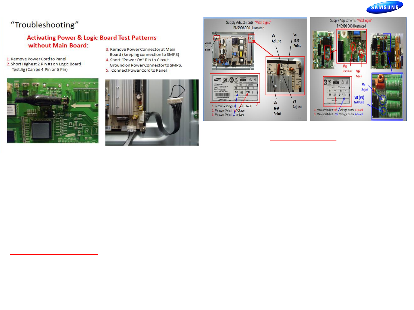
Power Supply Trouble Shooting Notes:
2010/2011 models
Will not be run with the “X” or “Y” main disconnected. The SMPS will
shut down immediately. However if a meter is first connected to the
test point when power is applied it will read the correct voltage briefly
before shut- ting down.(You have enough time to check key
voltages)
CAUTION: Do not reconnect any connectors to SMPS or Y/X Boards
until power has been turned off long enough for Vs to drop below 10V
or damage will occur to X or Y Boards.
SMPS Over Current Protection
If a short circuit occurs on either the VS or VA voltage lines, the SMPS
stops operating, but should not fail. When the short circuit is removed
from the source line, the Power Supply will operate normally again.
Many SMPS Supplies are replaced needlessly!
Sample
“VITAL SIGNS”
When troubleshooting, It’s very important to first check Vs, Va, Vsc & Ve
If Vs is missing (0V), disconnect power and check for short. Use ohm
meter to measure resistance while disconnecting Y-Board & X-Board
supply feeds one at a time.
Turn Power On and Test SMPS with shorted connector removed for
correct Vs voltage verification. (It may only come up briefly but to full
level). Be careful not to reconnect power connectors until Vs falls below
10V.
If Va is low or missing, disconnect power connectors to Address Boards
and Check to see if SMPS Supply is restored. (Note Va feed normally
passes through the Y-Drive to the Address Boards (Logic Buffer Boards).
If Vsc is low or missing and Vs is OK, the failure is with the Y-Board
.
since the Y-Board generates the Vsc voltage from the supplied Vs.
If Ve is low or missing and Vs is OK, the failure is with the X-Board since the
Ve is generated by the X-Board from the supplied Vs. (Please note: In some
rare cases the Ve is generated by the Y-Board fed to the X-Board.)
Other SMPS Voltages:
Check Low Voltage feeds to the Main Board and other supplied Assemblies.
3
Page 4
PN59D8000FFXZA
Fast Track Troubleshooting Manual
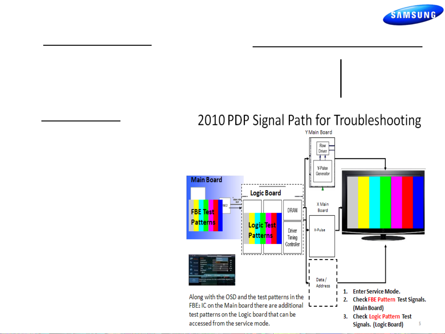
TROUBLESHOOTING VIDEO PROBLEMS
1. Verify Video Operation
a) Customer Picture Test (if available)
b) “Display” (If display is OK source is suspected)
c) Substitute with known good Source
(external DVD or Signal Generator)
3. Determine cause
a) If Logic pattern is NG; Logic
board, Logic buffers or
Panel are suspect.
b) If FBE patterns is NG and
Logic is OK; Main or LVDS
cable are suspect.
c) If both are OK it is likely a
source issue.
2. Using Test Patterns in Service Mode
- ENTERING SERVICE MODE –
Customer Remote: Service Remote:
1. Power off 1. Power On
2. Mute, 182, Power 2. Info, Factory
4
Page 5
PN59D8000FFXZA
Model
Code
PN59D8000FFXZA
Side Label
Option
Type
Model
Tuner
Light
Effect
Ch
Table
Country
Front Color
I101
59DSCrD
PD8000
SEC_Si2173
OFF
USA
P-W-VIO
I202
59DSCrD
PD8000
SEC_Si2173
OFF
USA
P-W-VIO
Y503
59DSCrD
PD8000
SEC_Si2173
OFF
USA
P-W-VIO
Y504
59DSCrD
PD8000
SEC_Si2173
OFF
USA
P-W-VIO
Fast Track Troubleshooting Manual
ALIGNMENTS & OPTION BYTES :
1. Check/Adj. VS, VA, VE, & VSC according to Panel Label
and Diffusion test. (see bulletins for any special notes
before making changes)
2. Check/Set Option Bytes:
- ENTER SERVICE MODE -
a) Customer Remote: Power off; Mute, 182, Power On
b) Service Remote: Power On; Info, Factory
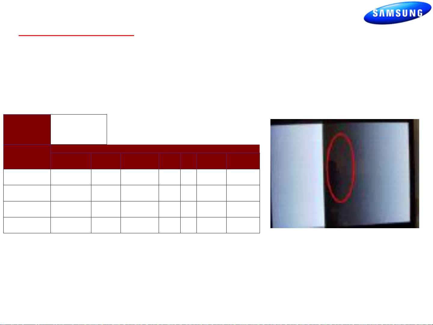
DIFFUSION TEST/ADJ. (cell miss-firing, older units)
- Allow the unit to warm up 15 to 20 minutes
- Access the Burn Protect Sig. Pattern in User
Menu.
-Adjust the Vs volts until screen errors are gone in
both dark and bright areas.
- Adjust the Vs volts within +/- 10V on the panel
label.
5
 Loading...