

Samsung PN50A650T1FXZA Quick Guide
1-800-SAMSUNG (7267864)
($-)).
Samsung Electronics America, Inc.
105 Challenger Road Ridgefield Park, NJ 07660-0511
Samsung Electronics Canada Inc., Customer Service
55 Standish Court Mississauga, Ontario L5R 4B2
Call center hours of operation (Mon-Sun 9AM-12AM EST).
www.samsung.com/global/register.
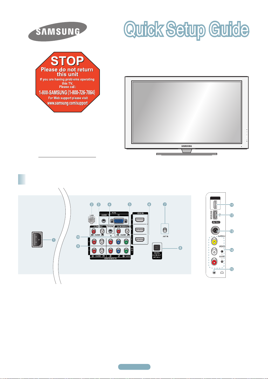
Rear & Side Panel Jacks
PN50A650T1F/ PN58A650T1F
1
POWER IN
2
LAN
3
AUDIO OUT (R/L)
4
PC IN[PC]/[AUDIO]
5
DVI IN (HDMI 2) (AUDIO-R/L)
6
HDMI IN 1, 2, 3
7
ANT IN
8
DIGITAL AUDIO OUT (OPTICAL)
9
COMPONENT IN 1, 2 / AV IN 1
0
EX-LINK
English - 1
!
HDMI IN 4
@
WISELINK
#
S-VIDEO (AV IN 2)
$
AV IN 2
%
HEADPHONE
Remote Control Buttons
You can use the remote control up to a distance of about 23 feet from the TV.
1
POWER
Turns the TV on and off.
2
TV
Selects the TV mode directly.
3
NUMERIC BUTTONS
Press to change the channel.
4
Press to select additional channels
(digital and analog) being broadcast
by the same station. For example,
to select channel “54-3”, press “54”,
then press “ ” and “3”.
5
MUTE
Press to temporarily cut off the
sound.
6
VOL
Press to increase or decrease the
volume.
7
SOURCE
Press to display and select the
available video sources.
8
CH LIST
Used to display Channel Lists on the
screen.
9
TOOLS
Use to quickly select frequently used
functions.
0
UP▲ / DOWN▼ / LEFT◄ /
RIGHT► / ENTER
Press the Up/Down/Left/Right
sections of the wheel button and
Enter to select on-screen menu
items and change menu values.
You can navigate up and down the
menu, switch channels and adjust
the volume by turning the wheel
button. (See pages 18~19 of the
owner's manual)
!
INFO
Press to display information on the
TV screen.
@
COLOR BUTTONS
Use these buttons in the Channel list
and WISELINK, etc.
#
CC
Controls the caption decoder.
$
E.MODE
Press to select the preset display
and sound modes for sports, cinema
and games.
%
Use these buttons in the DMA,
WISELINK and Anynet+ modes.
( : This remote can be used
to control recording on Samsung
recorders with the Anynet+ feature)
^
ON/OFF
Press to backlight the buttons on the
remote.
This function is convenient for using
at night or when the room is dark.
(Using the remote control with the
ON/OFF(
will reduce the battery usage time.)
&
PRE-CH
Tunes to the previous channel.
*
CH
Press to change channels.
(
MENU
Displays the main on-screen menu.
)
W.LINK(WISELINK)
This function enables you to view
and play photo and music files from
an external device. (Refer to pages
71 (Photo) and 81 (Music) of the
owner's manual)
a
RETURN
Returns to the previous menu.
b
EXIT
Press to exit the menu.
c
INFO.L
Press to use the News, Stock
Market and Weather Forecast
information services available over
the network.
(see page 95 of the owner's manual)
d
DMA (Digital Media Adapter)
Use this when connecting a
Samsung DMA device through an
HDMI interface and switching to
DMA mode.
For more information on the
operating procedures, refer to the
user manual of the DMA.
This button is available when “
➢
e
P.SIZE
Picture size selection.
f
FAV.CH
Press to switch to your favorite
channels.
) light button set to On
Anynet+(HDMI-CEC)” is “On.
(see page 99 of the owner's
manual)
Video Input Performance Comparison
/
/
HDMI/DVI Best
PC/COMPONENT Better
S-VIDEO Good
VIDEO Normal
Audio Output Performance Comparison
OPTICAL (Digital) Best
AUDIO (Analog) Normal
English - 2
English - 3
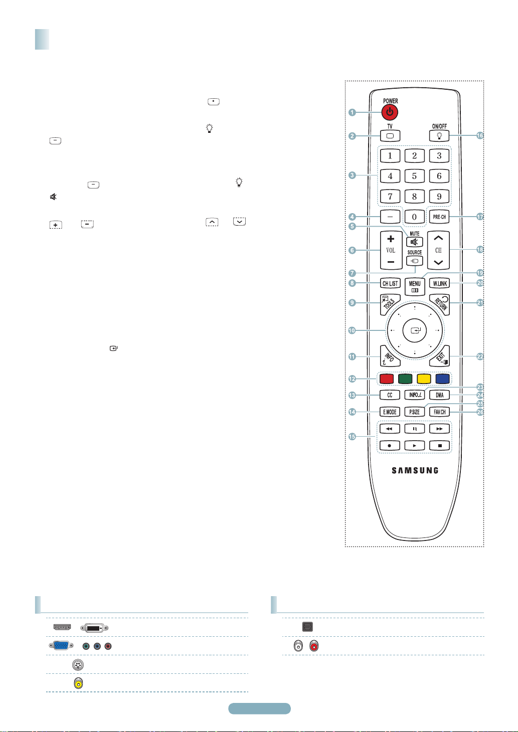
Connecting a DVD Player or Cable Box /
Satellite receiver (Set-Top Box) via HDMI
Connecting to HDMI (High Definition Multimedia Interface)
TV Rear Panel TV Side Panel
DVD Player or Cable Box /
Satellite receiver (Set-Top Box)
Connect an HDMI Cable between
the HDMI IN (1, 2, 3 or 4) jack on
the TV and the HDMI jack on the
DVD Player or Cable Box / Satellite
receiver (Set-Top Box).
Press the SOURCE button on the
remote control until you see the Set-
Top Box signal (see “To Select the
Source” on page 10).
HDMI Cable (Not supplied)
1
What is HDMI?
• HDMI, or high-definition multimedia interface, is an interface that enables the transmission of digital audio and video
signals using a single cable.
• The difference between HDMI and DVI is that the HDMI device is smaller in size and
Digital Copy Protection) coding feature installed.
➢
Each DVD Player or Cable Box / Satellite receiver (Set-Top Box) has a different back panel configuration.
➢
The TV may not output sound and pictures may be displayed with abnormal color when DVD Player or Cable Box / Satellite
receivers supporting HDMI versions older than 1.3 are connected. When connecting an older HDMI cable and there is no sound,
connect the HDMI cable to the HDMI IN 2 jack and the audio cables to the DVI IN (HDMI2) [R-AUDIO-L] jacks on the back of
the TV. If this happens, contact the company that provided the DVD Player or Cable Box / Satellite receiver to confirm the HDMI
version, then request an upgrade.
➢
HDMI cables that are not 1.3 may cause annoying flicker or no screen display.
h
as the HDCP (High Bandwidth
Connecting a DVD Player or Cable Box /
Satellite receiver (Set-Top Box) via DVI
Connecting to DVI (Digital Visual Interface)
DVD Player or Cable Box /
Satellite receiver (Set-Top Box)
Audio Cable (Not supplied)
HDMI/DVI Cable (Not supplied)
TV Rear Panel
2
Connect a HDMI/DVI Cable or DVIHDMI Adapter between the HDMI
IN 2 jack on the TV and the DVI jack
on the DVD Player or Cable Box/
Satellite receiver (Set-Top Box).
Connect Audio Cables between the
DVI IN (HDMI 2)
[R-AUDIO-L] jack on the TV and the
DVD Player or Cable Box / Satellite
receiver (Set-Top Box).
Press the SOURCE button on the
remote control until you see the Set-
Top Box signal (see “To Select the
Source” on page 10).
1
➢
Each DVD Player or Cable Box / Satellite receiver (Set-Top Box) has a different back panel configuration.
➢
When connecting a DVD Player or Cable Box / Satellite receiver (Set-Top Box), match the color of the connection terminal to the
cable.
➢
When using an HDMI / DVI cable connection, you must use the HDMI IN 2 jack.
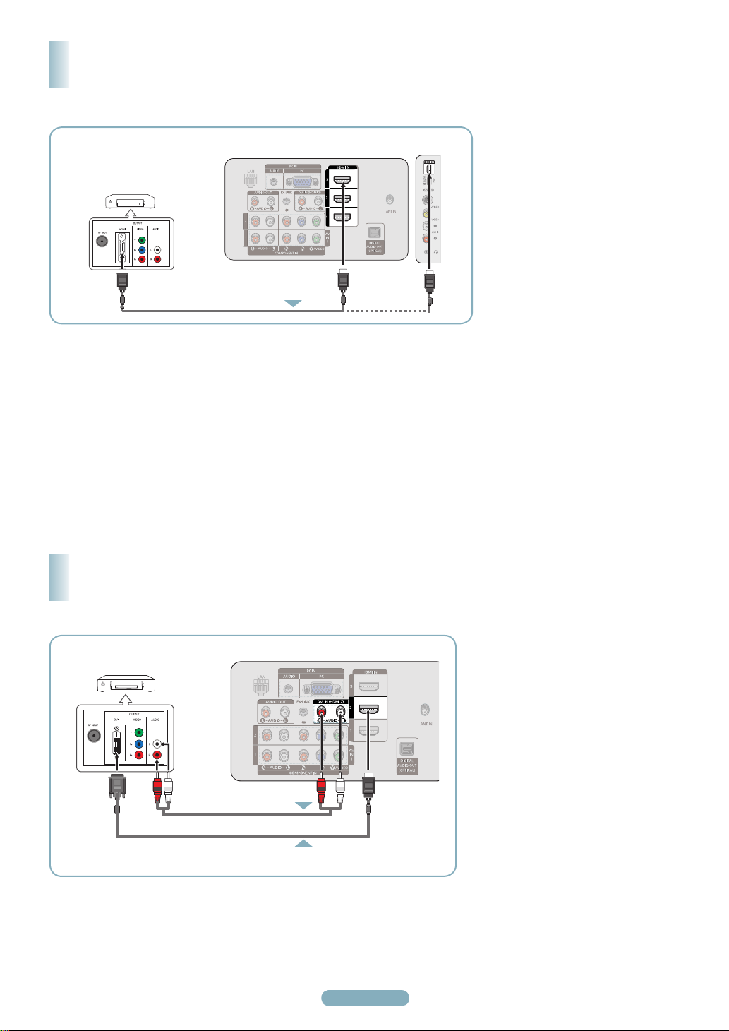
Connecting a DVD Player or Cable Box /
Satellite receiver (Set-Top Box) via Component cables
Connecting to Y, PB, PR
TV Rear Panel
DVD Player or Cable Box/
Satellite receiver (Set-Top Box)
2
Audio Cable (Not supplied)
Component Cable (Not supplied)
1
➢
Component video separates the video into Y (Luminance (brightness), PB (Blue) and PR (Red) for enhanced video quality. Be sure
to match the component video and audio connections. For example, if connecting a Component video cable to COMPONENT IN 1,
connect the audio cable to COMPONENT IN 1 also.
➢
Each DVD Player or Cable Box / Satellite receiver (Set-Top Box) has a different back panel configuration.
➢
When connecting a DVD Player or Cable Box / Satellite receiver (Set-Top Box), match the color of the connection terminal to the
cable.
Connect a Component Cable
between the COMPONENT IN (1 or
2) [Y, PB, PR] jacks on the TV and
the COMPONENT [Y, PB, PR] jacks
on the DVD Player or Cable Box /
Satellite receiver(Set-Top Box).
Connect Audio Cables between
the COMPONENT IN (1 or 2) [R-
AUDIO-L] jacks on the TV and the
AUDIO OUT jacks on the DVD
Player or Cable Box / Satellite
receiver (Set-Top Box).
Press the SOURCE button on the
remote control until you see the Set-
Top Box signal. (see “To Select the
Source” on page 10).
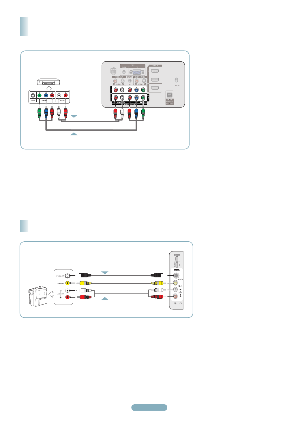
Connecting a Camcorder
1
Camcorder
or
2
S-Video Cable(Not supplied)
Video Cable (Not supplied)
Audio Cable (Not supplied)
TV Side Panel
Connect a Video Cable
(or S-Video Cable) between the AV
IN 2 [VIDEO] (or S-VIDEO) jack on
the TV and the VIDEO OUT jack on
the Camcorder.
Connect Audio Cables between the
AV IN 2 [L-AUDIO-R] jacks on the
TV and the AUDIO OUT jacks on
the Camcorder.
Press the SOURCE button on the
remote control until you see the
Camcorder signal (see “To Select
the Source” on page 10).
➢
Each Camcorder has a different back
panel configuration.
➢
When connecting a Camcorder, match
the color of the connection terminal to
the cable.
English - 4
English - 5
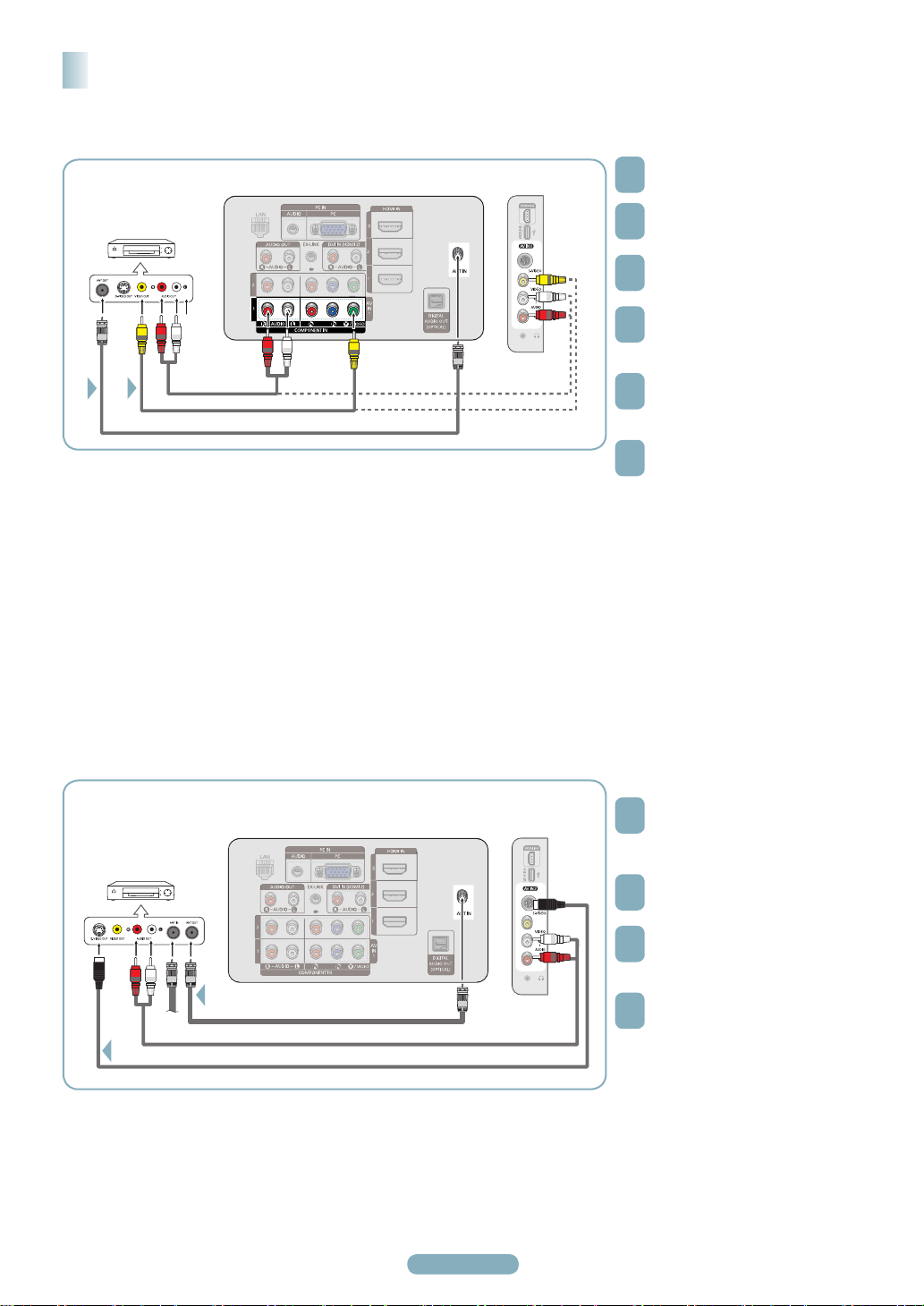
Connecting a VCR
Video Connection
Unplug the cable or antenna from
TV Rear Panel
VCR Rear Panel
2
1
➢
If you have a “mono” (non-stereo) VCR, use a Y-connector (not supplied) to connect to the right and left audio input jacks of the
TV. Alternatively, connect the cable to the “R” jack. If your VCR is stereo, you must connect two cables.
➢
Each VCR has a different back panel configuration.
➢
When connecting a VCR, match the color of the connection terminal to the cable.
➢
When connecting to AV IN 1, the color of the AV IN 1 [Y/VIDEO] jack (Green) does not match the color of the video cable (Yellow).
Audio Cable (Not supplied)
S-Video Cable (Not supplied)
Antenna Cable (Not supplied)
TV Side Panel
the back of the TV.
1
Connect the cable or antenna to the
ANT IN terminal on the back of the
2
VCR.
Connect an Antenna Cable between
the ANT OUT terminal on the VCR
3
and the ANT IN terminal on the TV.
Connect a Video Cable between the
VIDEO OUT jack on the VCR and
4
the AV IN 1 [Y/VIDEO] or AV IN 2
[VIDEO] jack on the TV.
Connect Audio Cables between the
AUDIO OUT jacks on the VCR and
5
the AV IN 1 (or AV IN 2)
[R-AUDIO-L] jacks on the TV.
Press the SOURCE button on the
remote control until you see the
6
VCR signal (see “To Select the
Source” on page 10).
S-Video Connection
TV Rear Panel
VCR Rear Panel
1
Antenna Cable (Not supplied)
Audio Cable (Not supplied)
2
An S-Video cable may be included with your VCR. (If not, check your local electronics store.)
➢
Each VCR has a different back panel configuration.
➢
When connecting a VCR, match the color of the connection terminal to the cable.
S-Video Cable (Not supplied)
TV Side Panel
To begin, follow steps 1–3 in the
previous section to connect the
1
antenna or cable to your VCR and
your TV.
Connect an S-Video cable between
the [S-VIDEO] jack on the TV and
2
the S-VIDEO OUT jack on the VCR.
Connect Audio Cables between the
AUDIO OUT jacks on the VCR and
3
the AV IN 2 [R-AUDIO-L] jacks on
the TV.
Press the SOURCE button on the
remote control until you see the
4
VCR signal (see “To Select the
Source” on page 10).
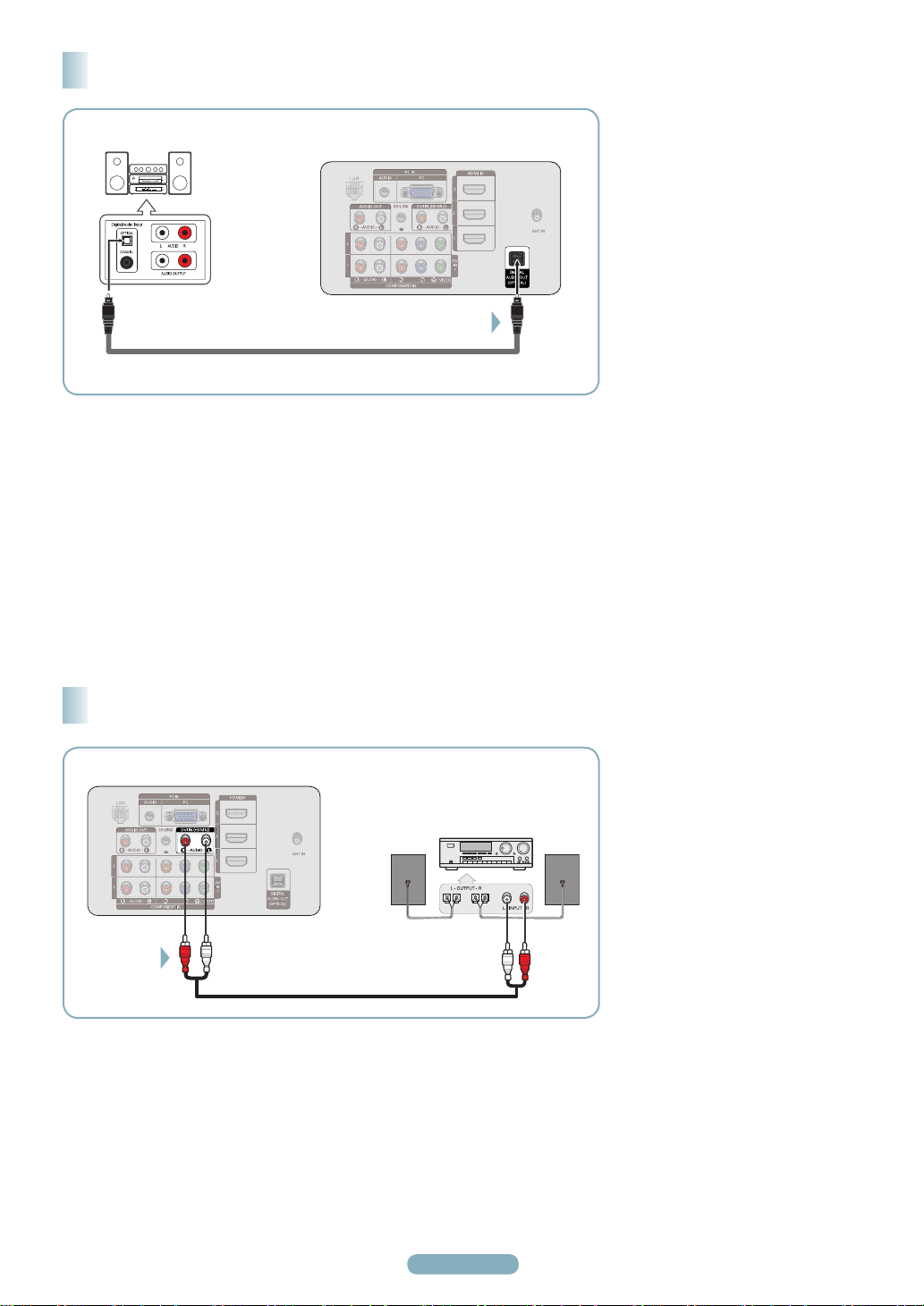
Connecting a Digital Audio System
Digital Audio System
TV Rear Panel
1
Optical Cable (Not supplied)
5.1CH audio is possible when the TV is connected to an external device supporting 5.1CH.
➢
Each Digital Audio System has a different back panel configuration.
➢
When the receiver (home theater) is set to On, you can hear sound output from the TV’s Optical jack. When the TV is displaying a
➢
DTV(air) signal, the TV will send out 5.1 channel sound to the Home theater receiver. When the source is a digital component such
as a DVD and is connected to the TV via HDMI, only 2 channel sound will be heard from the Home Theater receiver.
If you want to hear 5.1 channel audio, connect the DIGITAL AUDIO OUT (OPTICAL) jack on the DVD player or Cable/Satellite Box
directly to an Amplifier or Home Theater, not the TV.
Connect an Optical Cable
between the DIGITAL AUDIO OUT
(OPTICAL) jack on the TV and the
Digital Audio Input (OPTICAL) jacks
on the Digital Audio System.
When a Digital Audio System is
connected to the “DIGITAL AUDIO
OUT (OPTICAL)” jack: Decrease
the volume of the TV, and adjust
the volume level with the system’s
volume control.
What is OPTICAL?
• An optical cable converts an
electric signal into an optical
light signal, and transmits it
through glass fibers. S/PDIF is
a transmission system of digital
audio in the form of a light wave
that uses a glass conductor.
Connecting an Analog Amplifier / DVD Home Theater
TV Rear Panel
1
Amplifier/
DVD Home Theater
Audio Cable (Not supplied)
➢
Each Amplifier / DVD Home
Theater has a different back panel
configuration.
When connecting an Amplifier / DVD
➢
Home Theater, match the color of the
connection terminal to the cable.
Connect Audio Cables between the
AUDIO OUT [R-AUDIO-L] jacks on
the TV and AUDIO IN [L-AUDIO-R]
jacks on the Amplifier/DVD Home
Theater.
When an audio amplifier is
connected to the “AUDIO OUT
[R-AUDIO-L]” jacks terminals:
Decrease the volume of the TV,
and adjust the volume level with the
Amplifier’s volume control.
English - 6
English - 7
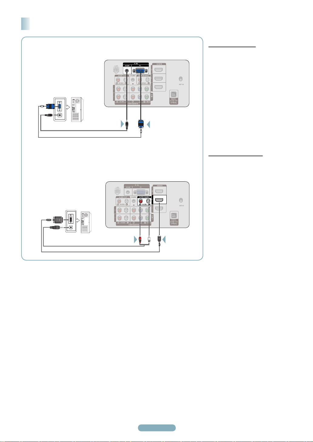
Connecting a PC
Using the D-Sub Cable
PC
PC Audio Cable (Not supplied)
D-Sub Cable (Not supplied)
Using the HDMI/DVI Cable
PC
Using the D-Sub Cable
TV Rear Panel
2
1
TV Rear Panel
Connect a D-Sub Cable between
PC IN [PC] jack on the TV and the
PC output jack on your computer.
Connect a PC Audio Cable between
the PC IN [AUDIO] jack on the TV
and the Audio Out jack of the sound
card on your computer.
Using the HDMI/DVI Cable
Connect a HDMI/DVI cable between
the HDMI IN 2 jack on the TV
and the PC output jack on your
computer.
Connect a 3.5 mm Stereo plug to
2RCA cable between the DVI IN
(HDMI2) [R-AUDIO-L] jack on the
TV and the Audio Out jack of the
sound card on your computer.
3.5 mm Stereo plug to RCA Cable (Not supplied)
HDMI/DVI Cable (Not supplied)
➢
Each PC has a different back panel configuration.
➢
When connecting a PC, match the color of the connection terminal to the cable.
➢
When using an HDMI/DVI cable connection, you must use the HDMI IN 2 terminal.
12
Turning the TV On and Off
Press the POWER button on the remote control.
You can also use the POWER button on the TV.
➢ It may take a while for the picture to appear.
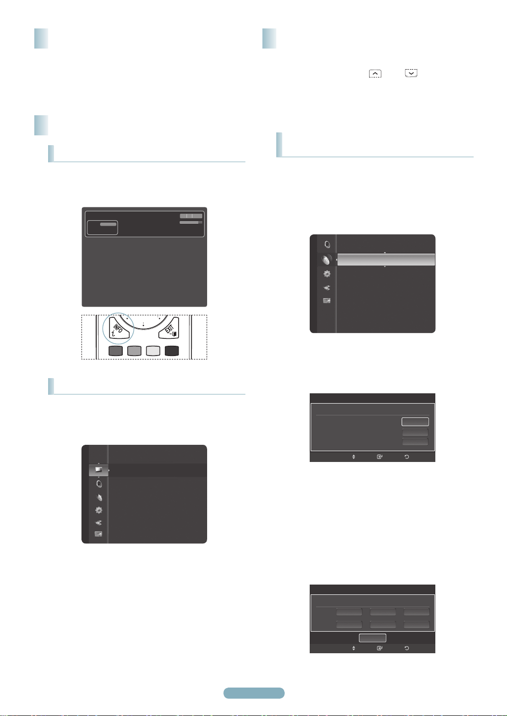
Viewing the Displays and Menus
Viewing the Display
Press the INFO button on the remote control.
The TV will display the channel, the type of sound,
and the status of certain picture and sound settings.
TV #1
DTV Air
13-1
Dolby Digital
Wed, Jan 2 12:28am
M. Spillane’s Mike Hammer
Bonocrunch
11:36 pm - 12:42 am
480i 4:3 English
Memorizing the Channels
Your TV can memorize and store all of the available channels
for both air and cable channels. After the available channels
are memorized, use the CH
through the channels. This eliminates the need to change
channels by entering the channel digits. There are three
steps for memorizing channels: selecting a broadcast source,
memorizing the channels (automatic) and adding and deleting
channels (Channel Lists).
Storing Channels in Memory
(Automatic Method)
Before your television can begin memorizing the available
channels, you must specify the type of signal source that is
connected to the TV (i.e. an Air or a Cable system).
Press the MENU button to display the menu.
Press the ▲ or ▼ button to select Channel, then
press the ENTER button.
Antenna : Air
Channel
Auto Program ►
Clear Scrambled Channel
Channel List
Fine Tune
Signal Strength
or CH
button to scan
Viewing the Menus
With the power on, press the MENU button.
The main menu appears on the screen. The menu’s
left side has icons: Picture, Sound, Channel,
Setup, Input, Application.
Picture
Mode : Standard
Cell Light : 7
Contrast : 80
Brightness : 45
Sharpness : 50
Color : 50
Tint (G/R) : G50/R50
Detailed Settings
Press the ▲ or ▼ button to select one of the icons.
Then press the ENTER button to access the icon’s
sub-menu.
➢
To move to a lower menu, turn the wheel
clockwise when the menu Display is on the
screen. To move to a higher menu, turn the
wheel counterclockwise.
Press the EXIT button to exit.
➢
It takes about one minute until the on-screen
menu disappears.
English - 8
Press the ▲ or ▼ button to select Auto Program,
then press the ENTER button.
Auto Program
Select the Antenna source to memorize.
Air
Cable
Auto
Press the ▲ or ▼ button to select an antenna
connection, then press the ENTER button.
➢
Air: Air antenna signal.
Cable: Cable antenna signal.
Auto: Air and Cable antenna signals.
Auto Program
Select the cable system.
Analog
Digital
STD
HRC IRC
HRC IRCSTD
Start
Start
Start
Start
ReturnEnterMove
ReturnEnterMove
 Loading...