

Page 1
PN42C450B1DXZA
FIRMWARE
Please check for updates!
--6/25/10. 1006.0
-Buzzing noise level will be reduced
SERVICE BULLETINS
HELP : 1-888-751-4086 (Tech Support)
1-866-894-0637 (FE)
GSPN
http://gspn3.samsungcsportal.com
PLUS ONE
http://my.plus1solutions.net/clientPortals/samsung
HOT TIPS
-Power On Problems: (pg. 3)
-Video Problems: (pg. 4)
Fast Track Troubleshooting Manual - Rev 1/9/2012
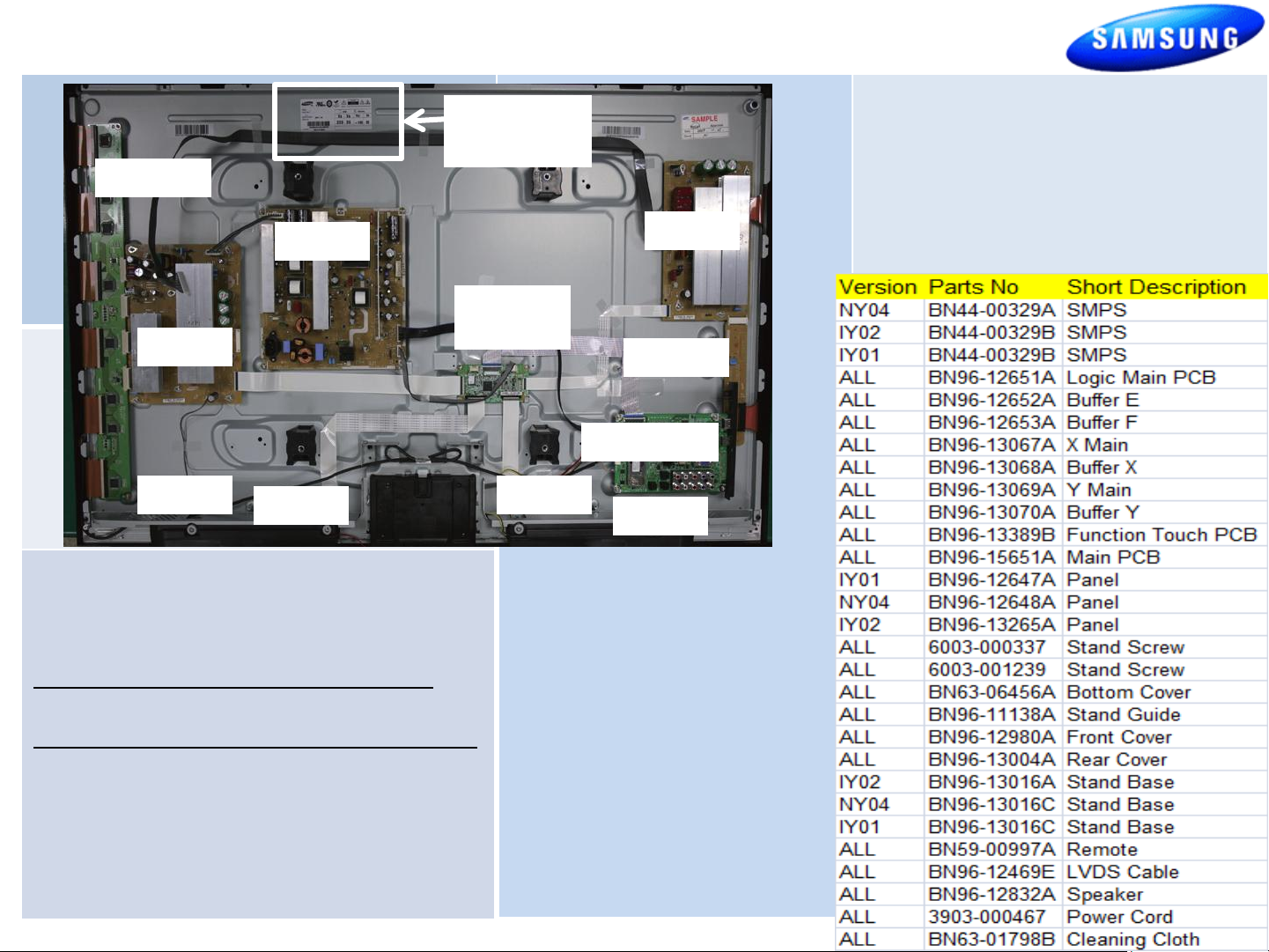
Vs Va Vsc Ve
Voltages
Buffer Y
SMPS
Y Main
Spkr R
X Main
Please check for parts updates!
Logic
Main PCB
Buffer X
Main PCB
Buffer F Buffer E
Spkr L
1
Page 2
Fast Track Troubleshooting Manual PN42C450B1DXZA
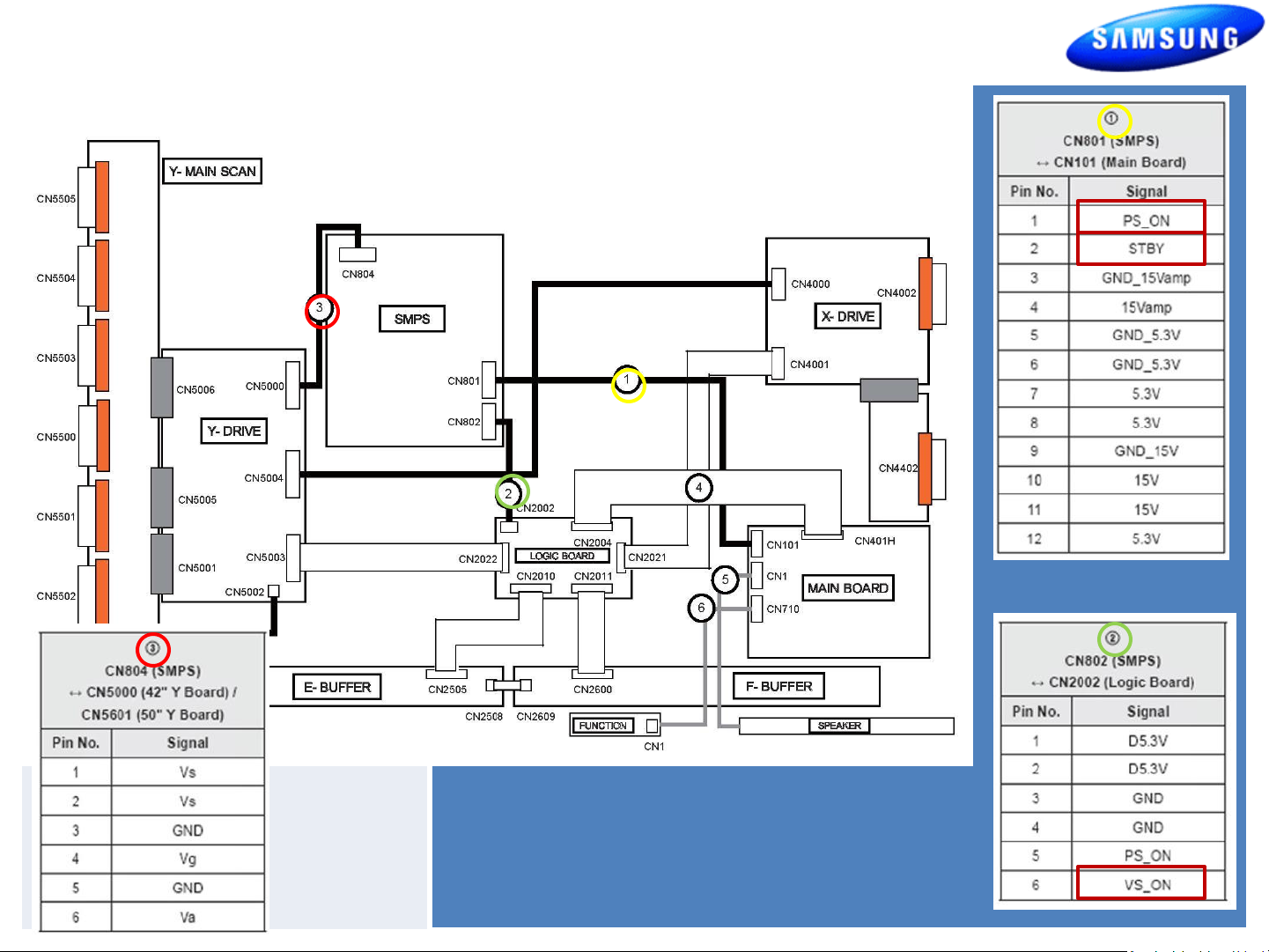
Power On Sequence
-STBY 5V (Pin 2 CN801)
-PS_ON (approx 3.3V – 0V) (Pin 1 CN801)
-VS_ ON (approx 0V – 3.3V) (Pin 6 CN802)
2
Page 3

Fast Track Troubleshooting Manual
Power Supply Trouble Shooting Notes:
2010/2011 models
Will not be run with the “X” or “Y” main disconnected. The SMPS will shut
down immediately. However if a meter is first connected to the test point
when power is applied it will read the correct voltage briefly before shut-
ting down.(You have enough time to check key voltages)
CAUTION: Do not reconnect any connectors to SMPS or Y/X Boards until
power has been turned off long enough for Vs to drop below 10V or damage
will occur to X or Y Boards. .
Over Current Protection
For the SMPS Power Supply... If a short circuit occurs on either the VS or
VA voltage lines, the SMPS stops operating, but should not fail. When the
short circuit is removed from the source line, the Power Supply will
operate normally again. Many SMPS Supplies are replaced needlessly!
SAMPLE VIEW & READINGS
. “VITAL SIGNS”
When troubleshooting, It’s very important to first check Vs, Va, Vsc & Ve
If Vs is missing (0V), disconnect power and check for short. Use ohm meter to
measure resistance while disconnecting Y-Board & X-Board supply feeds one
at a time.
Turn Power On and Test SMPS with short connector removed for correct Vs
voltage verification. (It may only come up briefly but to full level). Again be
careful not to reconnect Power Connectors until Vs falls below 10V.
If Va is low or missing, disconnect Supply Feed to Address Boards and
Check to see if SMPS Supply is restored. (Note Va feed normally passes
through the Y-Drive to the Address Boards (Logic Buffer Boards).
If Vsc is low or missing and Vs was OK, the failure is with the Y-Board
.
since the Y-Board generate the Vsc voltage from the Vs supplied by the
SMPS.
If Ve is low or missing and Vs is OK, the failure is with the X-Board since the
Ve is generated by the X-Board from the Vs supplied by the SMPS. Please note
in some rare cases the Ve may be generated by the Y-Board feed to the XBoard.) Other SMPS Voltages:
Check Low Voltage feeds to the Main Board and other supplied Assemblies.
3
Page 4

Fast Track Troubleshooting Manual
TROUBLESHOOTING VIDEO PROBLEMS
1. Verify Video Operation
a) Customer Picture Test (if available)
b) “Display” (If display is OK source is suspected)
c) Substitute with known good Source
(external DVD or Signal Generator)
3. Determine cause
a) If Logic pattern is NG; Logic
board, Logic buffers or Panel
are suspect.
b) If FBE patterns is NG and Logic
is OK; Main or LVDS cable are
suspect.
c) If both are OK it is likely a
source issue.
2. Using Test Patterns in Service Mode
- ENTERING SERVICE MODE -
Customer Remote Service Remote
1. Power off 1. Power On
2. Mute, 182, Power 2. Info, Factory
4
Page 5

Page 6

ALIGNMENTS:
Fast Track Troubleshooting Manual
SPECIAL NOTES:
See bulletin “Red Dots” for correction/
adjustments for this model.
1. Check/Adj. VS, VA, VE, & VSC according to Panel Label
and Diffusion test. (see bulletins for any special notes
before making changes)
2. Check/Set Option Bytes:
- ENTER SERVICE MODE -
Customer Remote
1. Power off
2. Mute, 182, Power
Service Remote
1. Power On
2. Info, Factory
DIFFUSION TEST/ADJ. (cell miss-firing, older units)
- Allow the unit to warm up 15 to 20 minutes
- Access the Burn Protect Sig. Pattern in Cust. Menu.
-Adjust the Vs volts until screen errors are gone in
both dark and bright areas.
- Adjust the Vs volts within +/- 10V on the panel label.
6
 Loading...