

Samsung PN22NSBU, PN22NS Troubleshooting
PN22N* 5-1
5 Troubleshooting
5-1 Parts Level Troubleshooting
Notes: 1. If a picture does not appear, fully rotate the brightness and contrast controls clockwise and reinspect.
2. Check the following circuits.
• No raster appears: Power circuit, Horizontal output circuit, H/V control circuit, and H/V output circuit.
• High voltage develops but no raster appears: Video output circuits.
• High voltage does not develop: Horizontal output circuits.
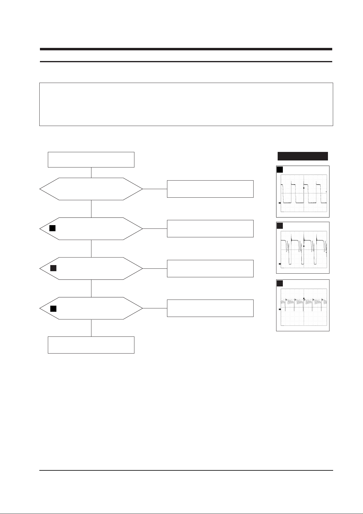
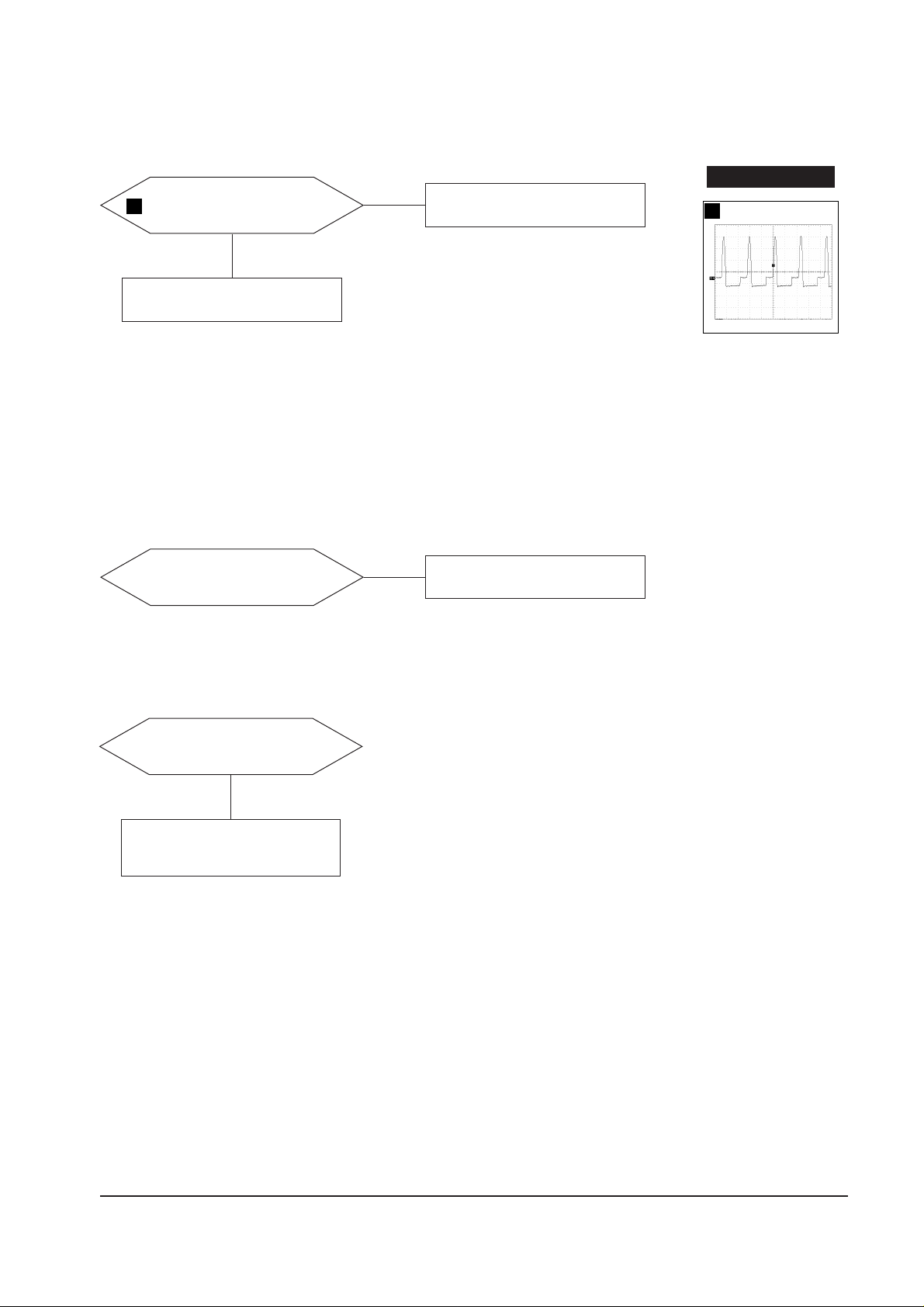
5-1-1 No Power Supply
Check and replace FH601, D601,
Q601, Q604, and IC611.
Done.
Repeating start?
Done.
No
Yes
IC611 Drain waveform is right?
Check and replace IC611.
Yes
No
Q601 Drain waveform is right?
Check IC601 and D602.
Yes
No
Q604 Drain waveform is right?
Check IC602 and IC603.
Yes
No
WAVEFORMS
5
2
Q601 Drain
CH1 RMS = 226.0V
4
Q604 Drain
CH1 RMS =434.4V
5
IC611 Drain
CH1 RMS = 333.2V
2
4
5 Troubleshooting
5-2 PN22N*
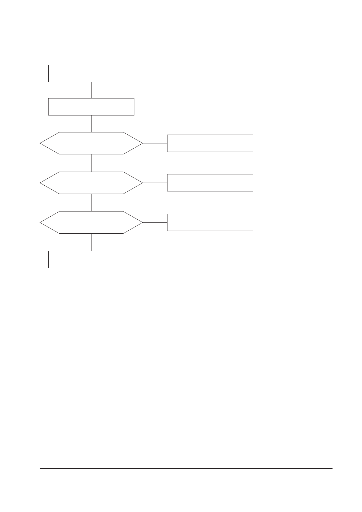
5-1-2 DPMS Failure
Check signal source
H/V sync video level.
Make No H/V sync (power off mode)
LED toggle green color, blinks?
Check IC201 Pin 30 and 31.
Yes
No
IC201 Pin9 High?
Check IC201 Pin 9.
Yes
No
Heater voltage is off?
Check IC201 Pin 10.
Yes
No
Done
5 Troubleshooting
PN22N* 5-3
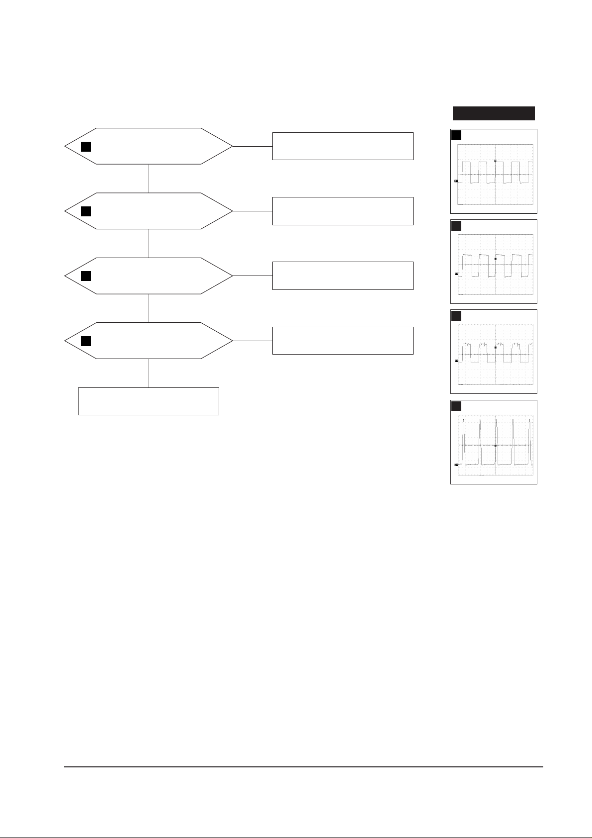
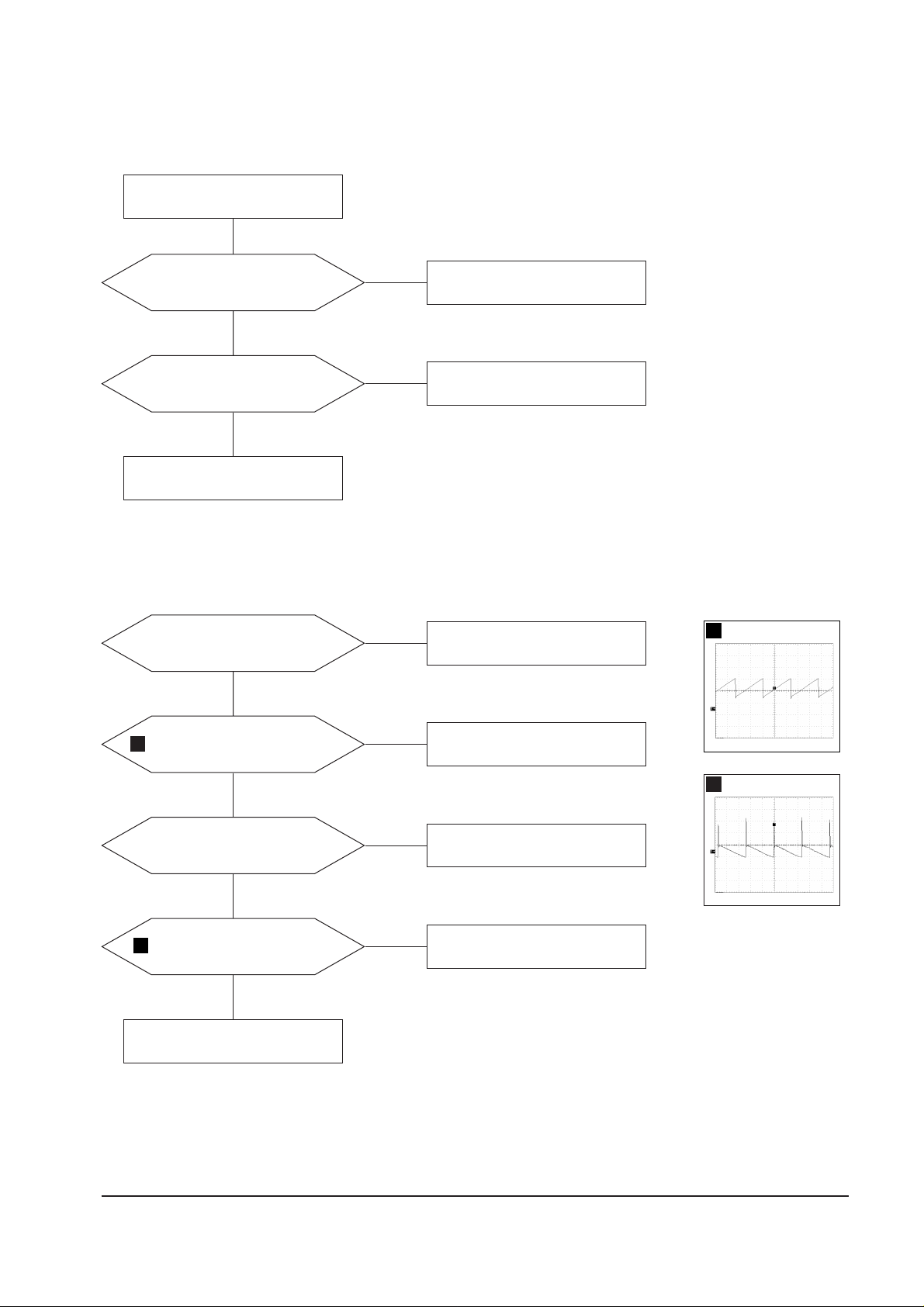
5-1-3 H_Deflection Failure
Q403 Drain waveform is right?
Check R403, D416 and +210 V line.
Yes
No
Q404 Gate
waveforms are right?
Check Q404 and R415.
Check +80 V line.
Yes
No
Q405 collector
waveforms are right?
Check and replace D410 and Q405.
Check DY connector connection.
Yes
No
Check some parts around
QS202 and QS203.
ICS202 Pin 26
waveform is right?
Check some parts around ICS202.
Yes
No
WAVEFORMS
20
21
23
14
14
ICS 202 #26
CH1 RMS = 8.88 V
21
Q404 Gate
CH1 RMS = 7.67 V
23
Q405 Collector
CH1 RMS =353.2 V
20
Q403 Drain
CH1 RMS = 188.4 V
5 Troubleshooting
5-4 PN22N*
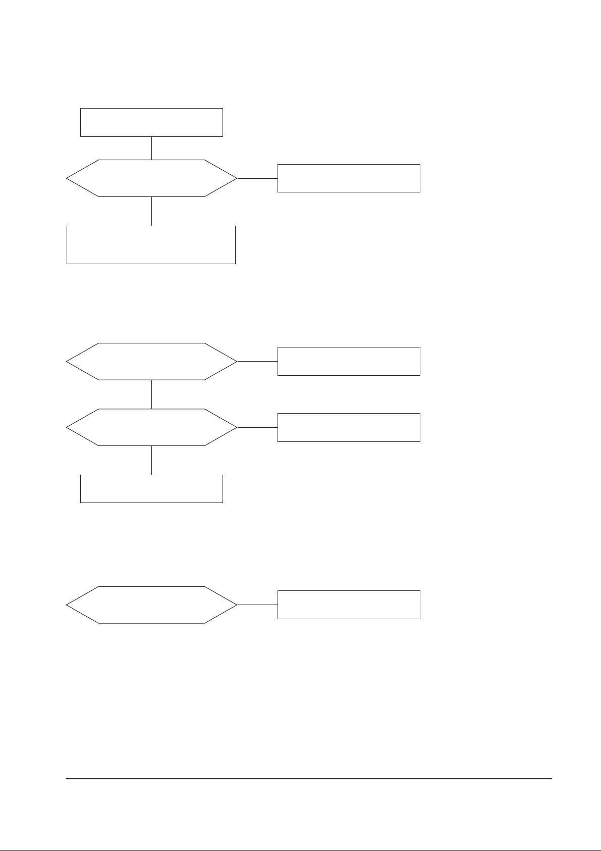
5-1-4 S_Correction Failure
S1~S6 signals are right at each
frequency block?
Check S1 ~ S6 signal.
Check and replace C451~ C457,
Q451~Q455, and Q456~Q460 .
Yes
5-1-5 H_Lin. Failure
ICS201 Pin 22 voltage varies with
different H_Lin. DAC values?
IC403 Pin 7 and 8 voltage varies
with different H_Lin. DAC values?
Check +12 V line.
Check some parts around IC403.
Check L403.
Yes
Yes
No
Check and replace ICS201.
No
Replace ICS201.
No
5-1-6 Invariable H_Size
ICS201 Pin 20 voltage varies with
different H_Size DAC values?
Check and replace ICS201.
No
5 Troubleshooting
PN22N* 5-5
5-1-7 Abnormal H_Size
T402 Pin 10 waveform is right?
Check and replace T402.
Check some parts
around ICS201 Pin 20
Yes
No
5-1-8 Side Pin or Trap Failure
ICS202 Pin 24 output exists?
Check and replace ICS202.
5-1-9 Para. or Pin Balance Failure
ICS202 Pin 24 output varies with
different DAC values?
No
Replace ICS202.
No
WAVEFORMS
19
19
T402 #10
CH1 RMS = 11.52 V
5 Troubleshooting
5-6 PN22N*
5-1-10 Tilt Failure
IC201 Pin 21 output duty varies
with different DAC values?
IC801 Pin 7 and 9 output varies
with different DAC values?
Check and replace IC801.
Check and replace Tilt coil.
Yes
Yes
No
Check and replace IC201.
No
Check tilt connector connection
5-1-11 V Deflection Failure
±13 V line is on?
ICS202 Pin 23 output exists?
Check and replace ICS202.
Yes
Yes
No
Check and replace D616 and D618.
No
IC301 Pin 1 input exists?
Check R300 and R304.
Yes
No
IC301 Pin 6 output exists?
Check and replace some parts
around IC301.
Yes
No
Check V DY connector connection.
16
25
16
ICS202 #23
CH1 RMS =3.668 V
25
IC301 #6
CH1 RMS = 8.72 V
 Loading...