

Samsung PN22NSBU, PN22NS Disassemble
3-1-1 Before making Disassembly
1. Disconnector signal cable and power cord
from the monitor.
2. With a pad beneath it, stand the monitor on its
front with the screen facing downward and
the base close to you.
3. Make sure nothing will damage the screen.
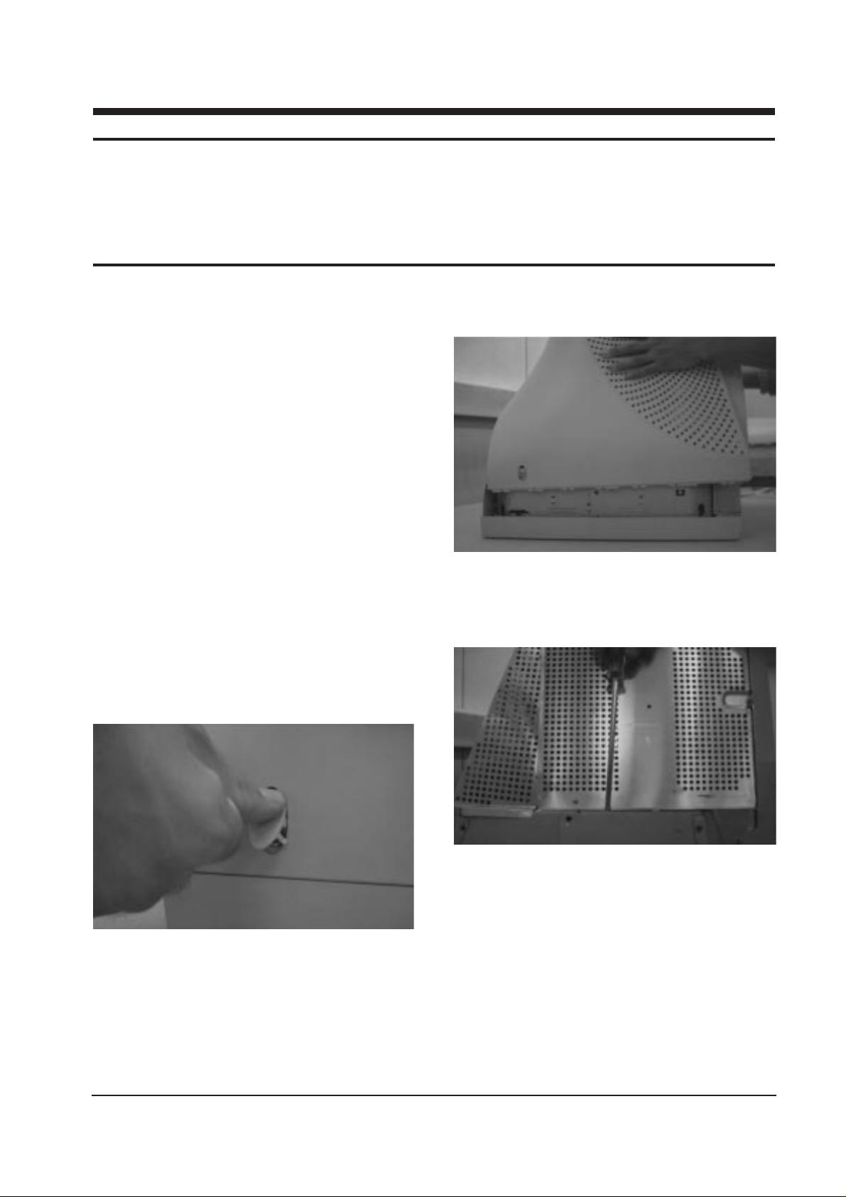
3-1-2 Cabinet Disassembly
1. With a pad beneath it, stand the monitor on its
front with the screen facing downward and
the base closest to you. Make sure nothing will
damage the screen.
2. Remove the Stand from the monitor.
(Refer to Stand manual)
3. Incline the monitor by lifting the rear of the
monitor.
4. Take out the screw caps on left/right top of
monitor.
5. Unscrew (4) and take the Rear Cover apart.
3-1-3 Removing the Top Shield
Remove the 9 screws on the top shield cover
and remove the shield.
3-1-4 Removing the Power PCB Assembly
and the Power PCB
1. Remove the 3 screws on the Power Assembly
shield.
2. Disconnect CN603, CN604, CN602, CN881 and
wire of clamp holder and then CN601 from
PCB Assembly shield.
3. Remove the 2 screws on the PCB Assembly
rear shield and remove the shield
4. Remove the 4 screws on the PCB Assembly.
PN22N* 3-1
3 Disassembly and Reassembly
This section of the service manual describes the disassembly and reassembly procedures for the
PN22N* monitors.
WARNING: This monitor contains electrostatically sensitive devices. Use caution when handling
these components.
3-1 Disassembly
Cautions:1. Disconnect the monitor from the power source before disassembly.
2. Follow these directions carefully; never use metal instruments to pry apart the cabinet.
Figure 3
Figure 2
Figure 1

3-1-5 Removing the BNC PCB Assembly and
the BNC PCB
1. Disconnect CN801, CN802, CN803, CN804,
CN202, CN204, CN205 on the BNC PCB
Assembly shield and remove the shield.
2. Remove the 2 screws from PCB Assembly
shield outside.
3. Remove the 2 cable ties, disconnect CN10 on
the small PCB Assembly.
4. Remove the 7 screws from PCB Assembly and
remove the PCB Assembly.
3-1-6 Removing the Video PCB Assembly
and the Video PCB
1. Disconnect 2 wires from BNC Assembly shield
and remove Video Assembly from the CRT
neck.
2. Disconnect 3 wires from Main PCB Assembly
and wires of clamp holder.
3. Desolder the 4 points on the video rear shield
and remove the shield.
4. Remove the 3 screws on the Video Assembly
shield inside and remove the shield from
Video PCB.
3-1-7 Removing the Main PCB Assembly
and the Main PCB
1. Remove chassis ground wire on the lift side.
2. Remove the 4 screws on the Bottom shield.
3. Disconnect CN901, CNS211, CNS201, H_DY,
V_DY and anode cap on the Main PCB
Assembly.
4. Remove 5 screws on the Main PCB.
3-1-8 Removing the Bracket
Remove the 10 screws on the Front Cabinet.
3 Disassembly and Reassembly
3-2 PN22N*
3-2 Reassembly
Reassembly procedures are in the reverse order of Disassembly procedures.
 Loading...