Samsung Plasma, Treinamento Schematic

PDP Training (Alexander)

Agenda

1.Explanation of Layout and Function of Circuit Board

2.Operation Explanation per Board

2-1 Drive Description on SMPS

2-2 Operation Explanation of Driving Circuit

2-3 Logic-Main Board

2-4 Scaler Board

Samsung Plasma, Treinamento Schematic

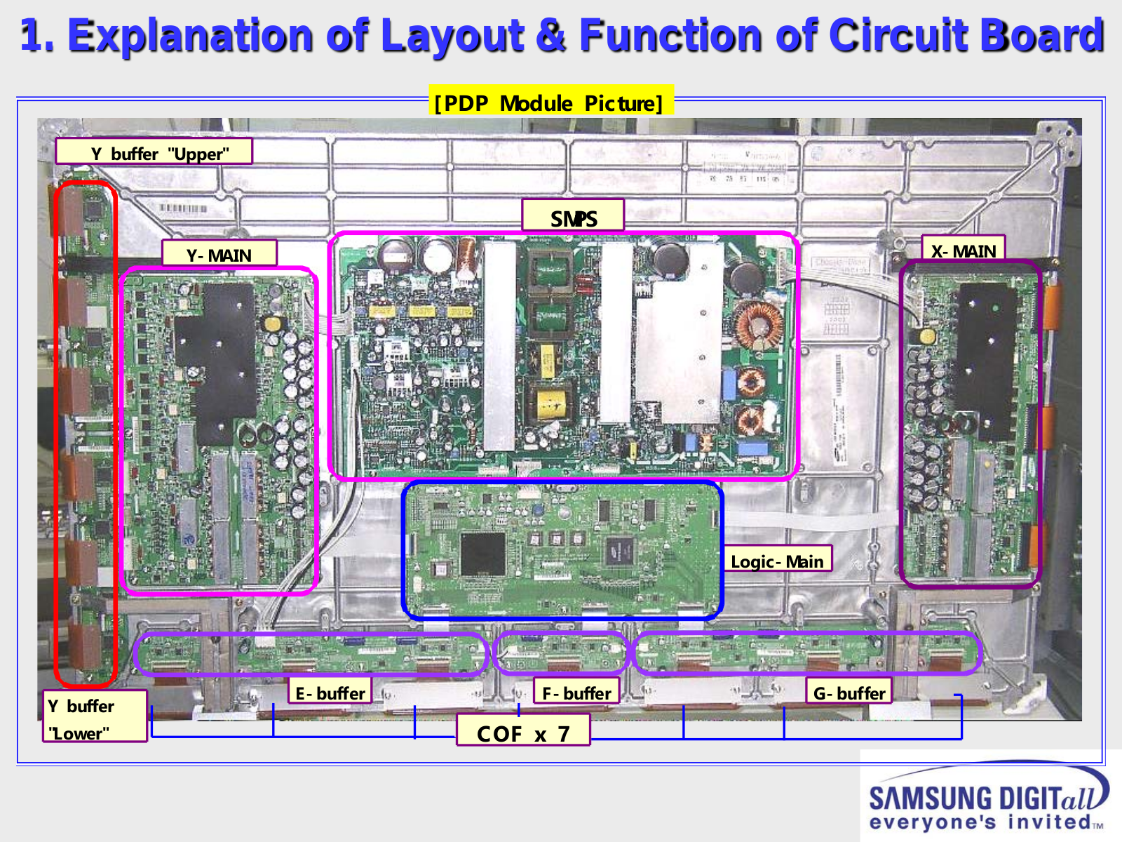
1. Explanation of Layout & Function of Circuit Board

[PDP Module Picture]

Y buffer "Upper"

Y- MAIN

SMPS

X- MAIN

LogicMain


E- buffer


F- buffer


G- buffer


Y buffer


"Lower"


COF x 7


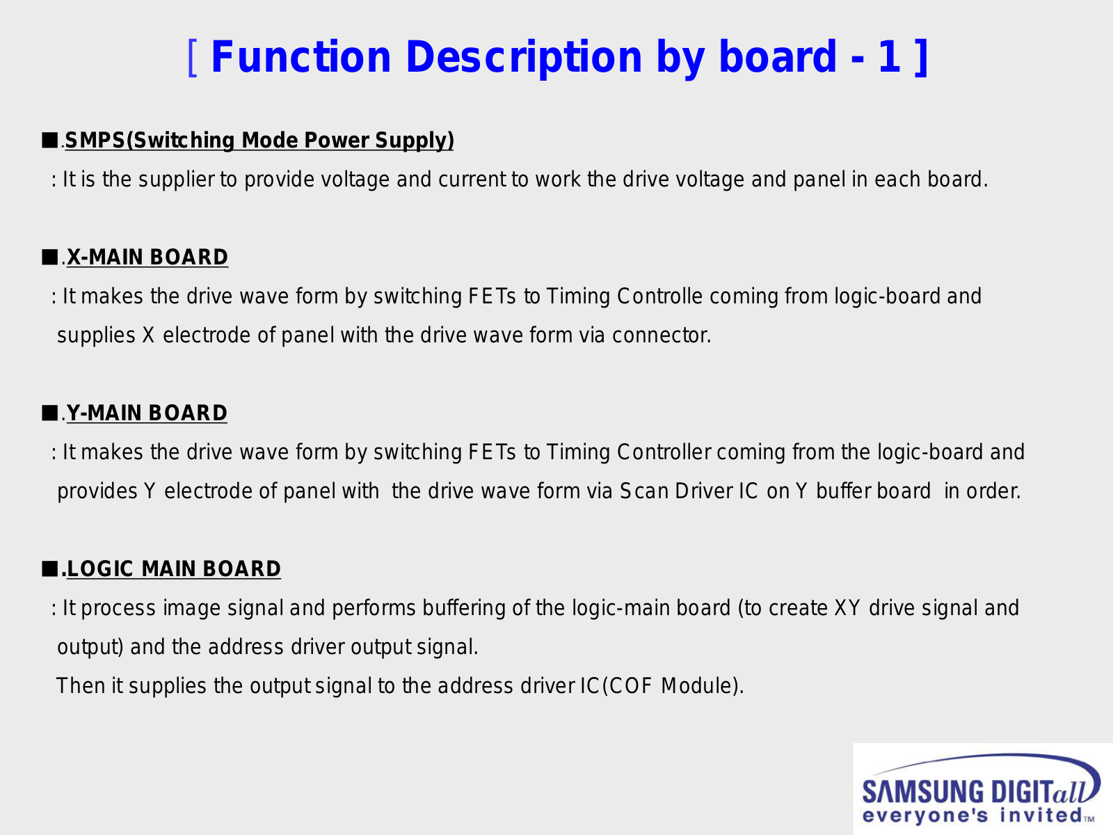
[ Function Description by board - 1 ]

■.SMPS(Switching Mode Power Supply)

: It is the supplier to provide voltage and current to work the drive voltage and panel in each board.

■.X-MAIN BOARD

: It makes the drive wave form by switching FETs to Timing Controlle coming from logic-board and supplies X electrode of panel with the drive wave form via connector.

■.Y-MAIN BOARD

: It makes the drive wave form by switching FETs to Timing Controller coming from the logic-board and provides Y electrode of panel with the drive wave form via Scan Driver IC on Y buffer board in order.

.LOGIC MAIN BOARD

: It process image signal and performs buffering of the logic-main board (to create XY drive signal and output) and the address driver output signal.

Then it supplies the output signal to the address driver IC(COF Module).

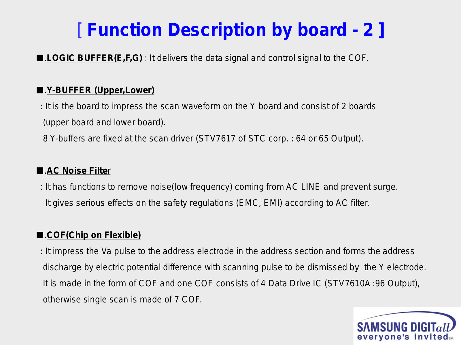
[ Function Description by board - 2 ]

■.LOGIC BUFFER(E,F,G) : It delivers the data signal and control signal to the COF.

■.Y-BUFFER (Upper,Lower)

: It is the board to impress the scan waveform on the Y board and consist of 2 boards (upper board and lower board).

8 Y-buffers are fixed at the scan driver (STV7617 of STC corp. : 64 or 65 Output).

■.AC Noise Filter

:It has functions to remove noise(low frequency) coming from AC LINE and prevent surge. It gives serious effects on the safety regulations (EMC, EMI) according to AC filter.

■.COF(Chip on Flexible)

: It impress the Va pulse to the address electrode in the address section and forms the address discharge by electric potential difference with scanning pulse to be dismissed by the Y electrode. It is made in the form of COF and one COF consists of 4 Data Drive IC (STV7610A :96 Output), otherwise single scan is made of 7 COF.

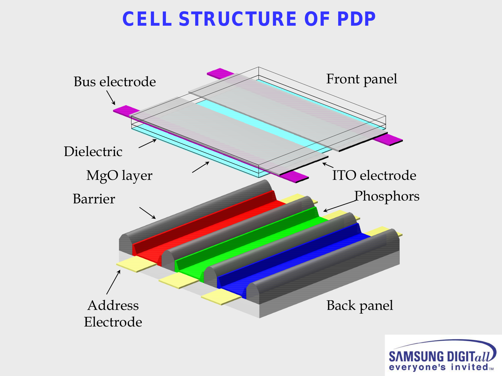
CELL STRUCTURE OF PDP

Bus electrode

Front panel

Dielectric


MgO layer

ITO electrode

Barrier

Phosphors

Address

Back panel

Electrode


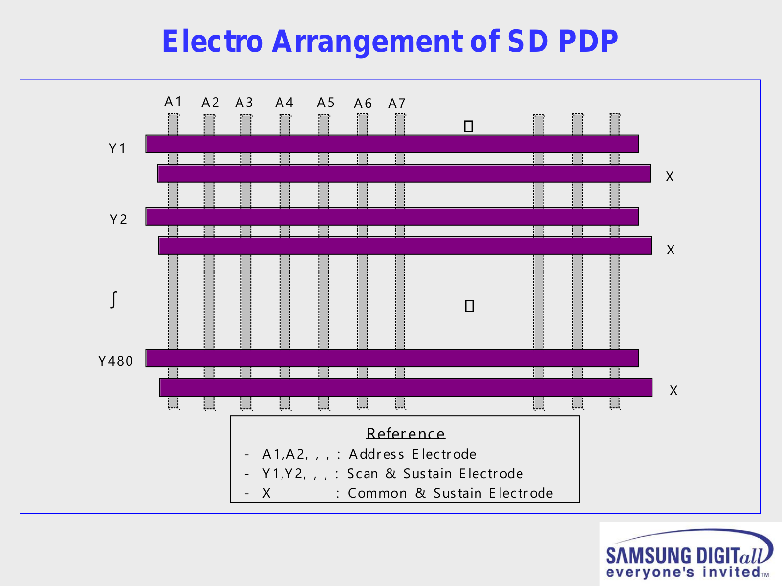
Electro Arrangement of SD PDP


A 1 A 2 A 3 A 4 A 5 A 6 A 7


Y 1


X

Y 2


X


Y 480


X


Refer ence


-

A 1,A 2,

,

,

: A ddr es s E lectr ode

-

Y 1,Y 2,

,

,

: Scan & Sus tain E lectr ode

-

X


: Common & Sus tain E lectr ode

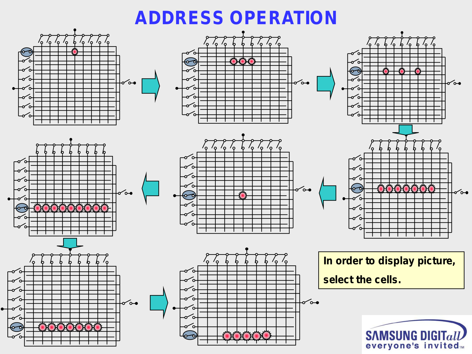
ADDRESS OPERATION

In order to display picture, select the cells.

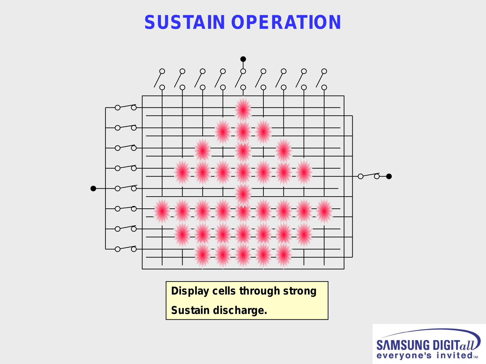
SUSTAIN OPERATION

Display cells through strong

Sustain discharge.

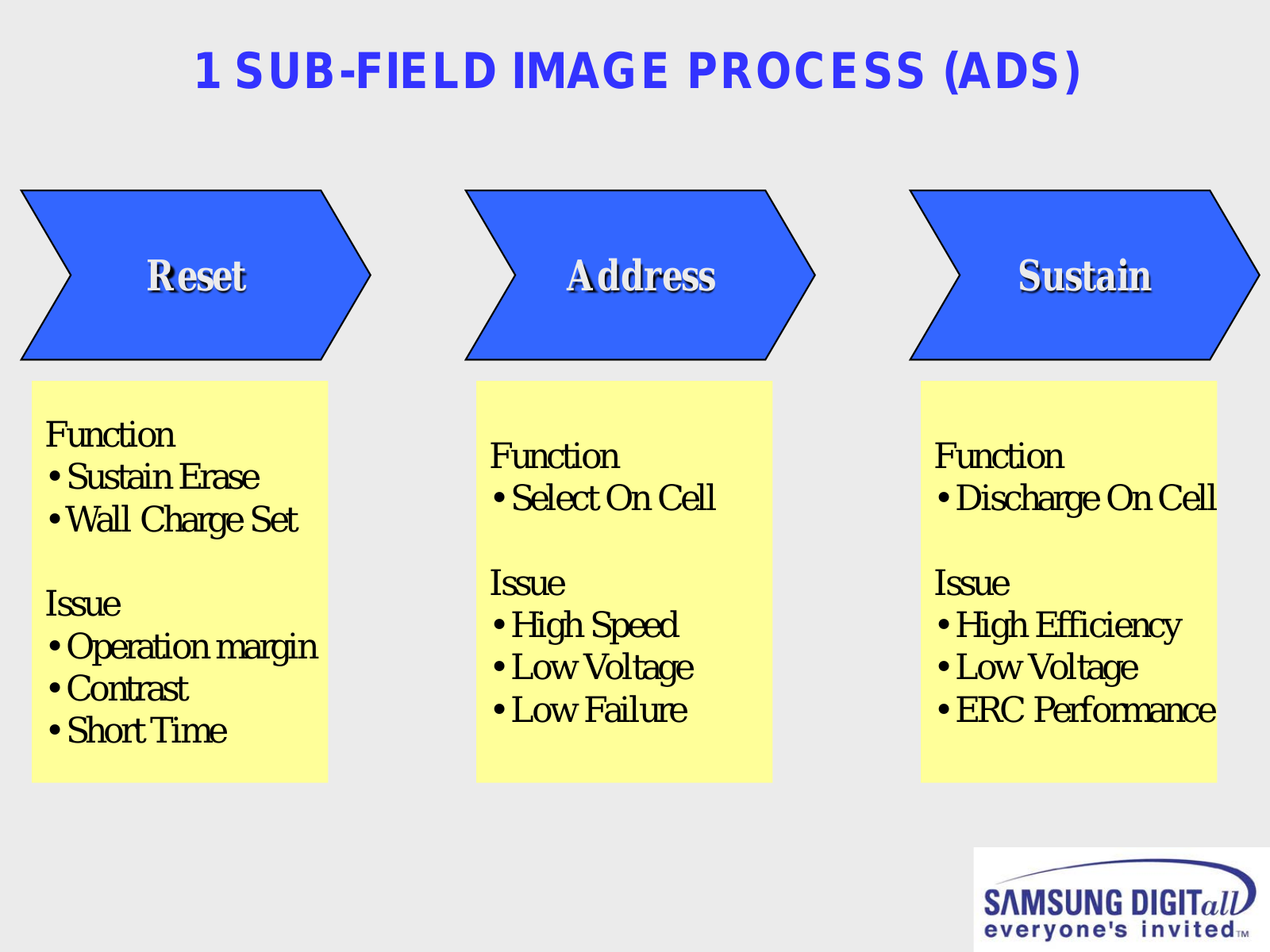
1 SUB-FIELD IMAGE PROCESS (ADS)

Reset

Function

Sustain Erase

Wall Charge Set

Issue

Operation margin

Contrast

Short Time

Address

Sustain


Function


Function


• Select On Cell


• Discharge On Cell


Issue


Issue


• High Speed


• High Efficiency


• Low Voltage


• Low Voltage


• Low Failure


• ERC Performance


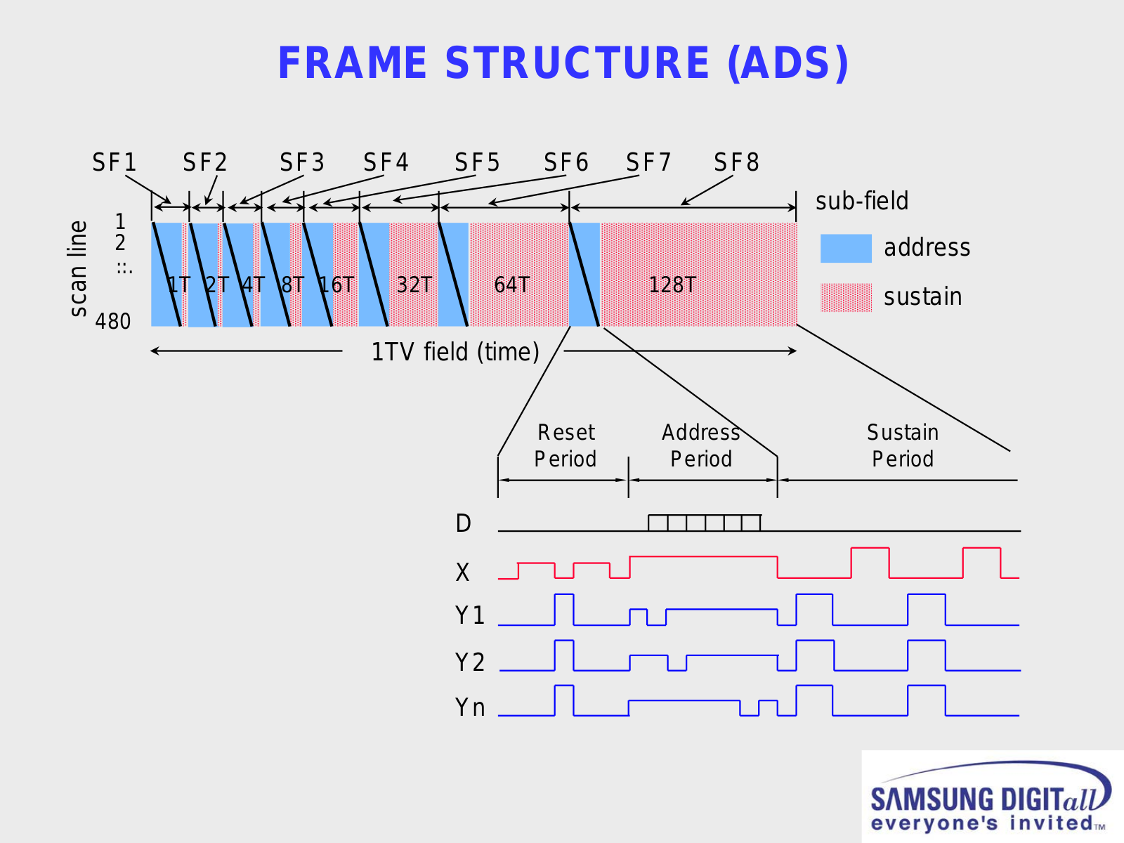
FRAME STRUCTURE (ADS)

scan line

SF1

1

2

..

...

480

SF2

SF3 SF4 SF5 SF6 SF7 SF8

sub-field address

1T 2T 4T

8T 16T

32T

64T

128T

sustain


1TV field (time)

Reset


Address


Sustain

Period


Period


Period


D

X

Y1

Y2

Yn

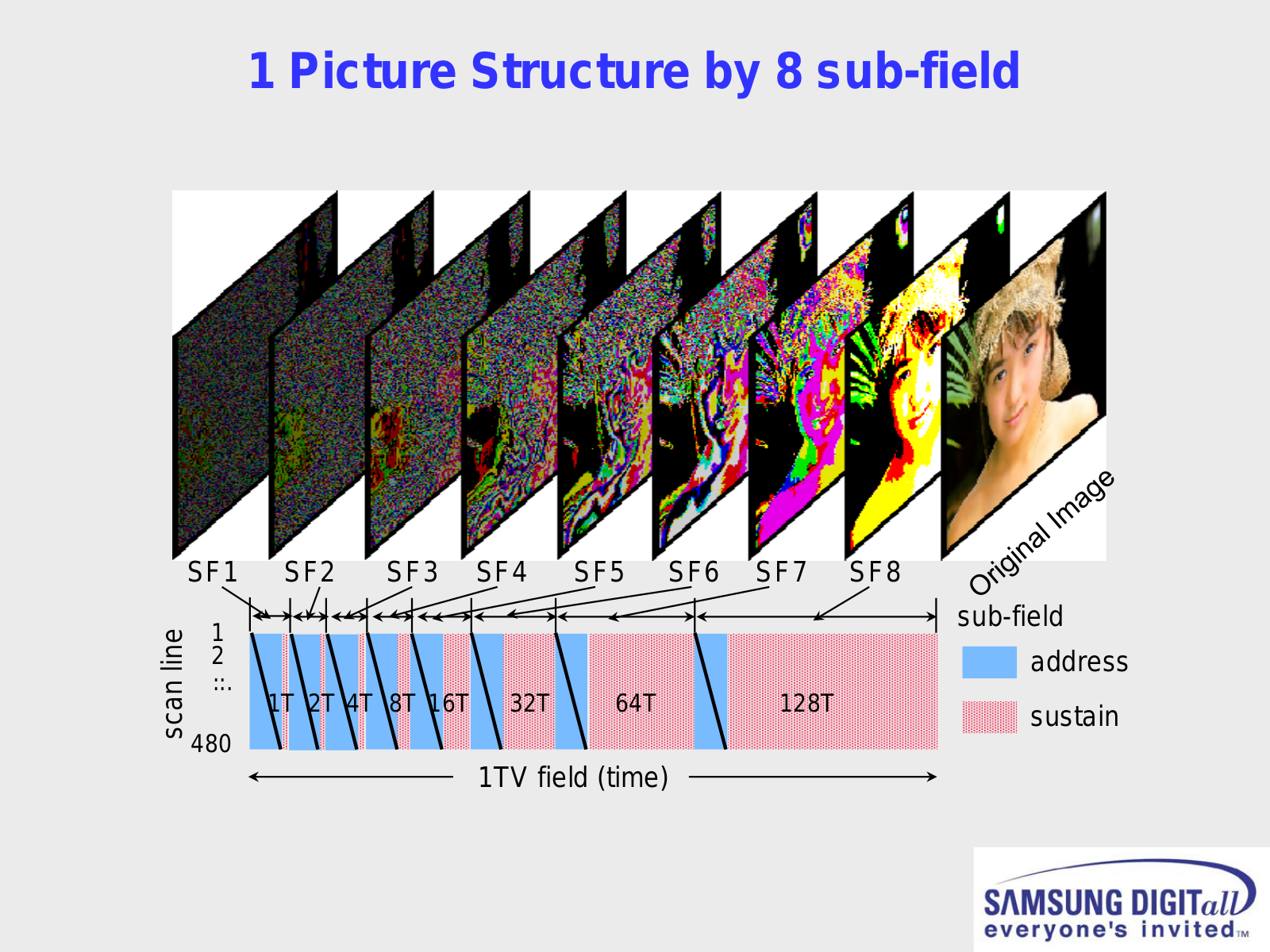
1 Picture Structure by 8 sub-field

scan line

SF1

1

2

..

...

480

SF2 SF3

SF4


SF5 SF6

SF7 SF8


sub-field


1T 2T 4T 8T 16T


32T


64T


128T


address


sustain


1TV field (time)

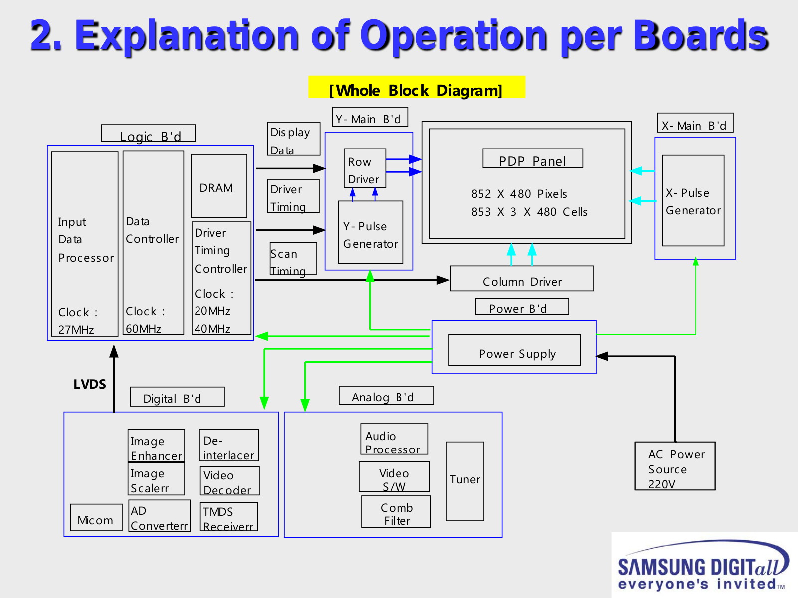
2. Explanation of Operation per Boards


[Whole Block Diagram]


Dis play

Y- Main

B 'd


Logic B'd


Data

Row

PDP Panel


DRAM

Driver

Driver

852 X 480 Pixels


Timing


Input

Data


853 X 3 X 480 Cells


Driver


Y- Pulse

Data

Controller


Generator

Timing


Scan

Processor


Controller

Timing


Column Driver


Clock

:


Power B 'd

Clock :

Clock :

20MHz


27MHz

60MHz

40MHz


Power Supply


LVDS


Digital B 'd


Analog B 'd


Audio


Image


De-


Processor


E nhancer


interlacer


Image


Video


Video


Tuner


Scalerr


Decoder


S/W


Comb


Micom


AD


TMDS


Converterr


Receiverr


Filter


X- Main B 'd

X- Pulse

Generator

AC Power Source 220V

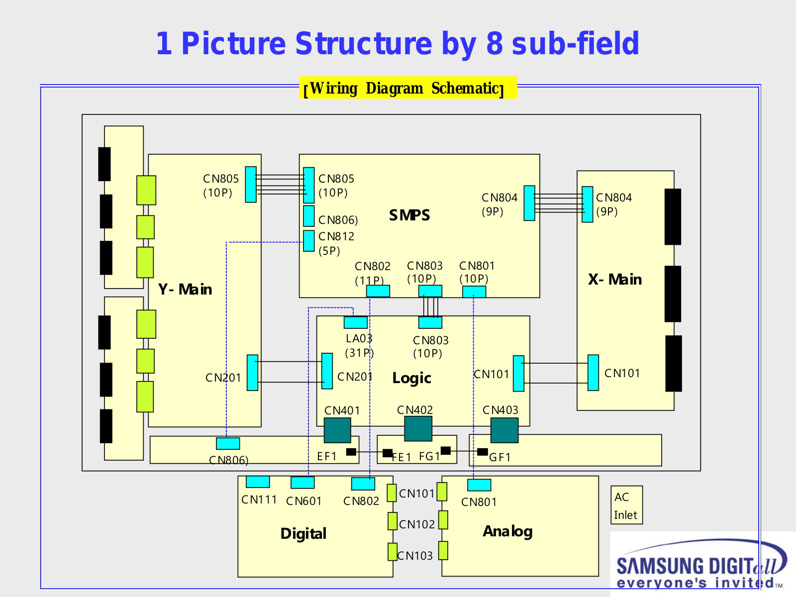
1 Picture Structure by 8 sub-field

[Wiring Diagram Schematic]

CN805 (10P)

Y- Main

CN201

CN806)


CN805


(10P)


CN804


CN806)

SMPS


(9P)


CN812


(5P)


CN801


CN802 CN803


(11P)


(10P)

(10P)


LA03


CN803


(31P)


(10P)


CN101


CN201

Logic


CN401

CN402


CN403


E F1


FE 1 FG1


GF1


CN804 (9P)

X- Main

CN101


CN101


AC


CN111 CN601 CN802


CN801


Digital


CN102


Analog


Inlet


CN103


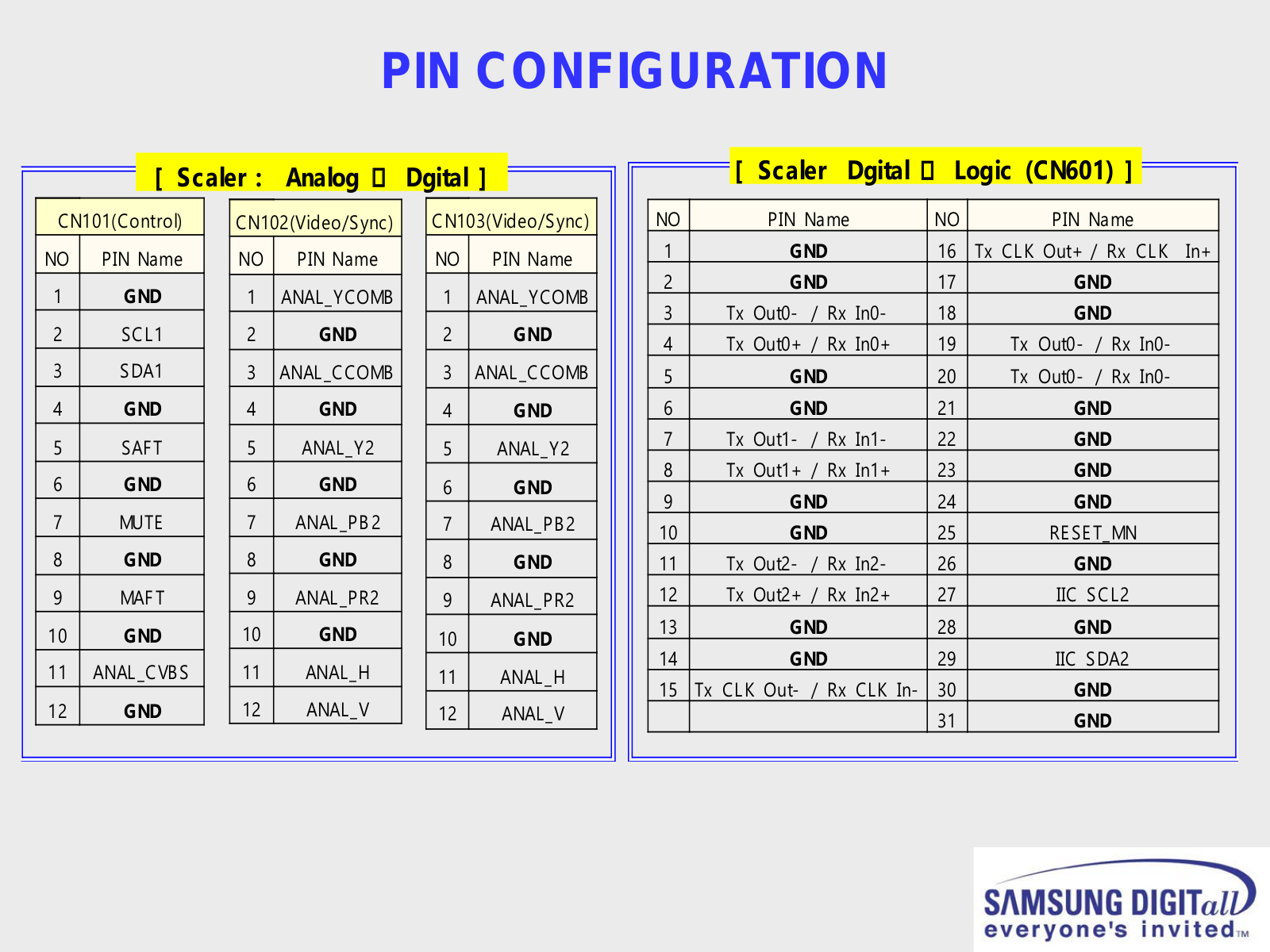
PIN CONFIGURATION


[ Scaler :

Analog


Dgital ]


CN101(Control)


CN102(Video/Sync)


CN103(Video/Sync)


NO

PIN Name


NO

PIN Name


NO

PIN Name


1

GND


1

ANAL_YCOMB


1

ANAL_YCOMB


2

SCL1


2

GND


2


GND


3

SDA1


3

ANAL_CCOMB


3

ANAL_CCOMB


4

GND


4

GND


4


GND


5

SAFT


5

ANAL_Y2


5

ANAL_Y2


6

GND


6

GND


6


GND


7

MUTE


7

ANAL_PB 2


7

ANAL_PB 2


8

GND


8

GND


8


GND


9

MAF T


9

ANAL_PR2


9

ANAL_PR2


10

GND


10

GND


10


GND


11

ANAL_CVB S


11

ANAL_H


11

ANAL_H


12

GND


12

ANAL_V


12

ANAL_V


[ Scaler Dgital Logic (CN601) ]

NO

PIN Name


NO


PIN Name

1

GND


16

Tx CLK Out+ / Rx CLK In+

2

GND


17


GND

3

Tx Out0- / Rx

In0-

18


GND

4

Tx Out0+ / Rx

In0+

19

Tx

Out0-

/ Rx In0-

5

GND


20

Tx

Out0-

/ Rx In0-

6

GND


21


GND

7

Tx Out1- / Rx

In1-

22


GND

8

Tx Out1+ / Rx

In1+

23


GND

9

GND


24


GND

10

GND


25


RE SE T_MN

11

Tx Out2- / Rx

In2-

26


GND

12

Tx Out2+ / Rx

In2+

27


IIC SCL2

13

GND


28


GND

14

GND


29


IIC

SDA2

15

Tx CLK Out- / Rx

CLK In-

30


GND


31


GND

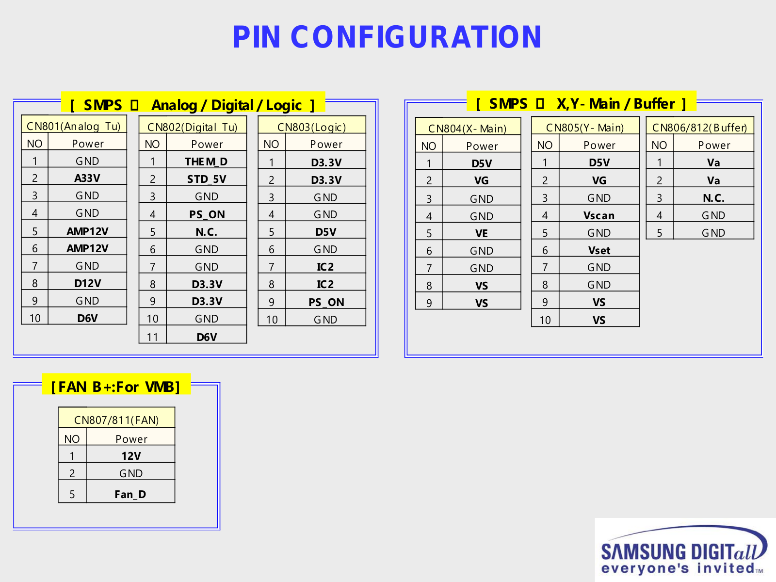
PIN CONFIGURATION


[ SMPS

Analog / Digital / Logic

]


CN801(Analog Tu)


CN802(Digital Tu)


CN803(Logic)


NO


Power


NO

Power


NO


Power


1


GND


1

THEM_D


1


D3.3V


2


A33V


2

STD_5V


2


D3.3V


3


GND


3

GND


3


GND


4


GND


4

PS_ON


4


GND


5


AMP12V


5

N.C.


5


D5V


6


AMP12V


6

GND


6


GND


7


GND


7

GND


7


IC2


8


D12V


8

D3.3V


8


IC2


9


GND


9

D3.3V


9


PS_ON


10


D6V


10

GND


10


GND


11

D6V


[ FAN B+:For VMB]

CN807/811( FAN)

NO Power

112V

2GND

5 Fan_D


[ SMPS

X,Y- Main / Buffer ]


CN804(X- Main)


CN805(Y- Main)


CN806/812( B uffer)


NO

Power


NO

Power


NO


Power


1


D5V


1

D5V


1


Va


2


VG


2

VG


2


Va


3


GND


3

GND


3


N.C.


4


GND


4

Vscan


4


GND


5


VE


5

GND


5


GND


6


GND


6

Vset


7


GND


7

GND


8


VS


8

GND


9


VS


9

VS


10

VS


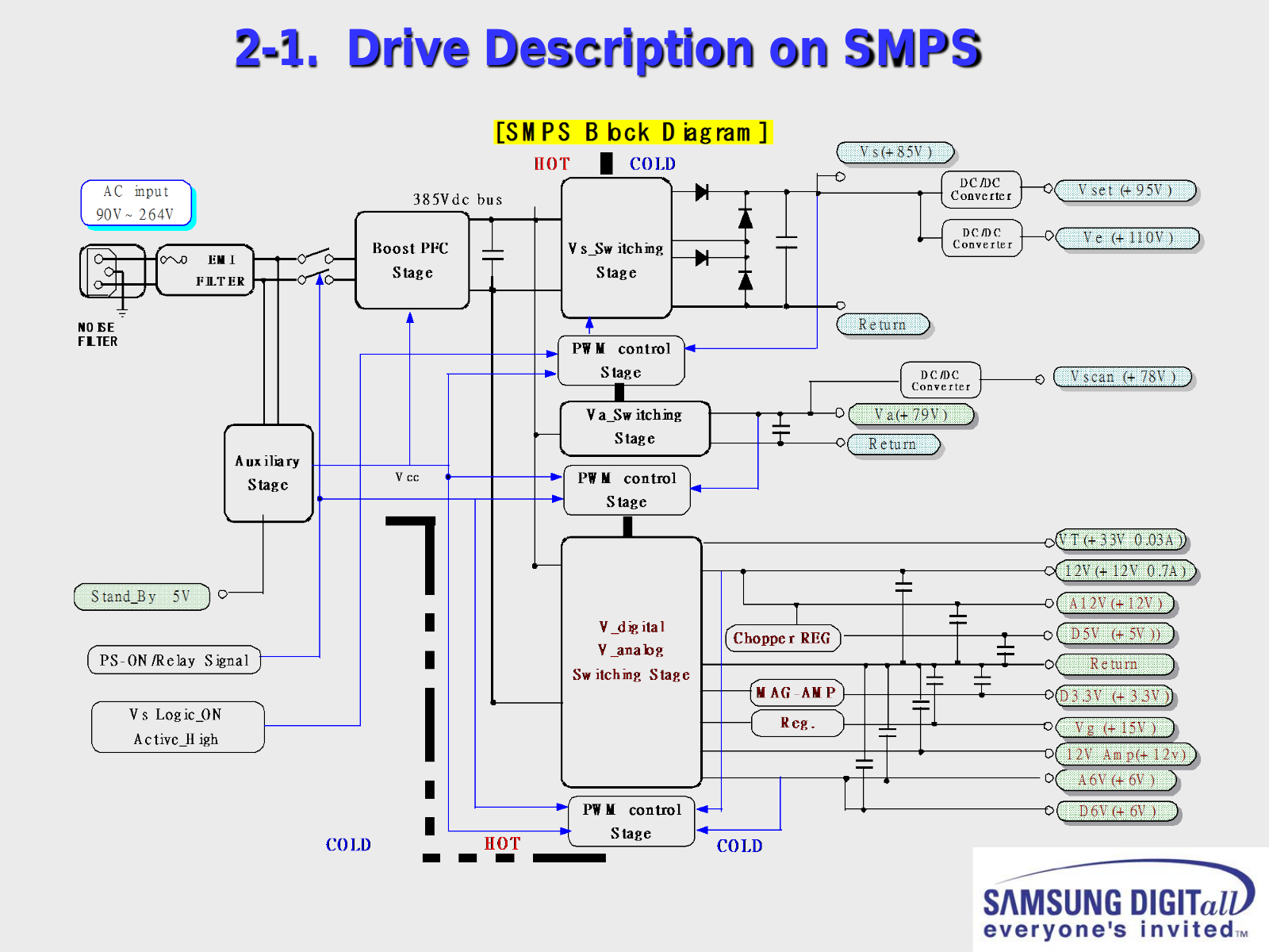
2-1. Drive Description on SMPS

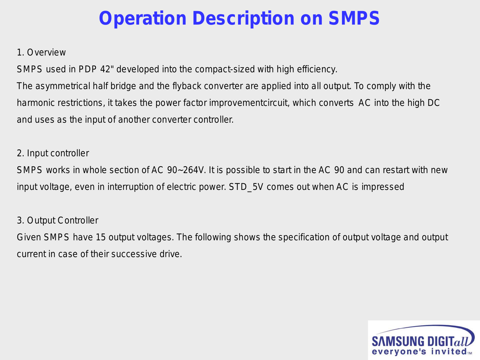
Operation Description on SMPS

1. Overview

SMPS used in PDP 42" developed into the compact-sized with high efficiency.

The asymmetrical half bridge and the flyback converter are applied into all output. To comply with the harmonic restrictions, it takes the power factor improvementcircuit, which converts AC into the high DC and uses as the input of another converter controller.

2. Input controller

SMPS works in whole section of AC 90~264V. It is possible to start in the AC 90 and can restart with new input voltage, even in interruption of electric power. STD_5V comes out when AC is impressed

3. Output Controller

Given SMPS have 15 output voltages. The following shows the specification of output voltage and output current in case of their successive drive.

Loading...
+ 39 hidden pages