

Page 1

E-MANUAL
Contate a SAMSUNG EM TODO O MUNDO
Caso tenha dúvidas ou comentários sobre os produtos da Samsung, entre em contato com o centro de atendimento ao cliente da
SAMSUNG.
País
ARGENTINA 0800-333-3733 www.samsung.com
BRASIL 0800-124-421
CHILE 800-SAMSUNG(726-7864) www.samsung.com
NICARAGUA 00-1800-5077267 www.samsung.com
HONDURAS 800-7919267 www.samsung.com
COSTA RICA 0-800-507-7267 www.samsung.com
EQUADOR 1-800-10-7267 www.samsung.com
EL SALVADOR 800-6225 www.samsung.com
GUATEMALA 1-800-299-0013 www.samsung.com
JAMAICA 1-800-234-7267 www.samsung.com
PANAMÁ 800-7267 www.samsung.com
PUERTO RICO 1-800-682-3180 www.samsung.com
REP. DOMINICANA 1-800-751-2676 www.samsung.com
TRINIDAD & TOBAGO 1-800-SAMSUNG(726-7864) www.samsung.com
VENEZUELA 0-800-100-5303 www.samsung.com
COLÔMBIA 01-8000112112 www.samsung.com
Assistência Técnica
4004-0000
Web Site
www.samsung.com
Plasma TV
Manual do Usuário
© 2011 Samsung Electronics Co., Ltd. All rights reserved.
imagine as possibilidades
Obrigado por comprar este produto Samsung.
Para receber um serviço mais completo, registre
seu produto no site:
www.samsung.com/register
BN68-03456A-00
Page 2

For more information on how to use e-Manual
Figures and illustrations in this User Manual are provided for reference only and may differ from actual product appearance.
Product design and specifications may be changed without notice.
Important User Information
• Screen Image retention
Do not display a still image (such as that from a video game) on the plasma display panel for more than a few minutes. Still images can cause screen
image retention (burn in). This avoid image retention is also known as ‘screen burn’. To avoid such image retention, reduce the degree of brightness
and contrast of the screen when displaying a still image.
• Heat on the top of the Plasma TV
The top side of the TV may become hot after long periods of use as heat dissipates from the panel through the vent hole in the upper part of the TV.
This is normal and does not indicate any defect or operational failure of unit.
However, children should be prevented from touching the upper part of the TV.
• The TV is making a ‘cracking’ noise.
A ‘cracking’ noise may occur when the TV contracts or expands due to a change in the surrounding environment such as temperature or humidity.
This is normal and not a defect.
• Cell Defects
The PDP uses a panel consisting of 2,360,000 (HD-level) to 6,221,000 (FHD-level) pixels which require sophisticated technology to produce.
However, there may be a few bright or dark pixels on the screen. These pixels will have no impact on the performance of the product.
• Avoid operating the TV at temperatures below 41°F (5°C)
• A still image displayed too long may cause permanent damage to the PDP Panel.
Watching the Plasma TV in 4:3 format for a long period of time may leave traces of the borders on the left, right, top, or bottom of
the screen. Playing a DVD or a game console may have a similar effect.
Damage caused by the above effect is not covered by the warranty.
• After-images on the Screen.
Displaying still images from Video games and PC for longer than a certain period of time may produce partial after-images.
To prevent this effect, reduce the ‘brightness’ and ‘contrast’ when displaying still images for a long time.
• Warranty
Warranty does not cover any damage caused by image retention.
Burn-in is not covered by the warranty.
Securing the Installation Space
Keep the required distances between the product and other objects (e.g. walls) to ensure proper ventilation.
Failing to do so may result in fire or a problem with the product due to an increase in the internal temperature of the product.
When using a stand or wall-mount, use parts provided by Samsung Electronics only.
✎
• If you use parts provided by another manufacturer, it may result in a problem with the product or an injury due to the product falling.
The appearance may differ depending on the product.
✎
Be careful when you contact the TV because some parts can be somewhat hot.
✎
Installation with a stand. Installation with a wall-mount.
4 inches
4 inches
4 inches
4 inches
Other Warnings
✎
The actual appearance of the TV may differ from the images in this manual, depending on the model.
✎
Be careful when you touch the TV. Some parts can be somewhat hot.
4 inches
4 inches
4 inches
English - 2
Page 3

Accessories
✎
Please make sure the following items are included with your TV. If any items are missing, contact your dealer.
✎
The items’ colors and shapes may vary depending on the models.
✎
Check that there are no accessories hidden behind packing materials when you open the box.
y Remote Control & Batteries (AAA x 2)
y Owner’s Instructions
y Warranty Card / Safety Guide
Ferrite Core (1EA)
✎
Ferrite Core : The ferrite cores are used to shield the cables from interference. When
connecting a cable, open the ferrite core and clip it around the cable near the plug as shown
in the figure.
y Cleaning-Cloth
y Power Cord
Antenna Cable/
Component Cable
(sold separately)
Input Cables (Sold Separately)
HDMI HDMI-DVI Component Composite (AV) Coaxial (RF) VGA
English - 3
Page 4
Viewing the Control Panel
✎
The product color and shape may vary depending on the model.
Control Panel
Remote control sensor Aim the remote control towards this spot on the TV.
Power Indicator Blinks and turns off when the power is on and lights up in standby mode.
SOURCE
MENU Displays an on-screen menu, the OSD (on screen display), which contains controls for
y
z
P
E
(Power)
Toggles between all the available input sources. In the on-screen menu, use this
button as you would use the ENTERE button on the remote control.
your TV’s features.
Adjusts the volume. In the OSD, use the
and ► buttons on the remote control.
Changes the channels. In the OSD, use the
▼ and ▲ buttons on the remote control.
Turns the TV on or off.
y
z
buttons as you would use the ◄
buttons as you would use the
Standby mode
Do not leave your TV in standby mode for long periods of time (when you are away on vacation, for example). A small amount
of electric power is still consumed even when the power button is turned off. It is best to unplug the power cord.
English - 4
Page 5

Installing the Wall Mount
Installing the Wall Mount Kit
The wall mount kit (sold separately) allows you to mount the TV on the wall.
For detailed information on installing the wall mount, see the instructions provided with the wall mount. We recommend you
contact a technician for assistance when installing the wall mount bracket. Samsung Electronics is not responsible for any
damage to the product or injury to yourself or others if you elect to install the wall mount on your own.
Wall Mount Kit Specifications (VESA)
✎
The wall mount kit is not supplied, but sold separately. Install your wall mount on a solid wall perpendicular to the floor.
When attaching to other building materials, please contact your nearest dealer. If installed on a ceiling or slanted wall, it
may fall and result in severe personal injury.
✎
NOTE
Standard dimensions for wall mount kits are shown in the table below.
x
When purchasing our wall mount kit, a detailed installation manual and all parts necessary for assembly are provided.
x
Do not use screws that do not comply with the VESA standard screw specifications.
x
Do not use screws that are longer than the standard dimension or do not comply with the VESA standard screw
x
specifications. Screws that are too long may cause damage to the inside of the TV set.
For wall mounts that do not comply with the VESA standard screw specifications, the length of the screws may differ
x
depending on the wall mount specifications.
Do not fasten the screws too strongly; this may damage the product or cause the product to fall, leading to personal
x
injury. Samsung is not liable for these kinds of accidents.
Samsung is not liable for product damage or personal injury when a non-VESA or non-specified wall mount is used or
x
the consumer fails to follow the product installation instructions.
Our 63” model do not comply with VESA Specifications. Therefore, you should use our dedicated wall mount kit for
x
this model.
Do not mount the TV at more than a 15 degree tilt.
x
Always use two people to mount the TV to a wall.
x
Product Family
PDP-TV
TV size in
inches
43~51 400 X 400
59~64 600 X 400
VESA screw hole
specs (A * B) in
millimeters
Standard Screw Quantity
M8 4
✎
Unscrew the hole around before installing Wall-Mount on the wall.
Do not install your Wall Mount Kit while your TV is turned on. It may result in personal injury due to
electric shock.
English - 5
Page 6

Viewing the Remote Control
✎
This remote control has Braille points on the Power, Channel, and Volume buttons and can be used by visually impaired
persons.
Turns the TV on and off.
Have direct access to channels.
Press to select additional channels
(digital) being broadcasted by the
same station. For example, to select
channel “54.3”, press “54”, then press
“–” and “3”.
Adjusts the volume.
Opens the OSD.
Displays the Content Home, which
include Watch TV, My Content and
Source.
Quickly select frequently used functions.
Selects the on-screen menu items and
changes the values seen on the menu.
Returns to the previous menu.
Displays and selects the available video
sources.
Returns to the prevlous channel.
Cuts off the sound temporarily.
Changes channels.
Displays channel lists on the screen.
Displays the EPG (Electronic Program
Guide)
Displays information on the TV screen.
Exits the menu.
These buttons are for the Channel
Manager or My Contents menu, etc.
Use these buttons in My Contents and
Anynet+ (HDMI-CEC) modes.
Installing batteries (Battery size: AAA)
E-MANUAL: Displays the e-Manual.
SRS: Selects the Sound Mode.
X
: Turns the 3D image on or off.
P.SIZE: Selects the Picture Size.
CC: Displays digital subtitles.
MTS: Press to choose stereo, mono
or Separate Audio Program (SAP
broadcast).
✎
NOTE
Use the remote control within 23 feet of the TV.
x
Bright light may affect the performance of the remote control.
x
Avoid using nearby special fluorescent light or neon signs.
The color and shape may vary depending on the model.
x
English - 6
Page 7

How to Navigate Menus
Before using the TV, follow the steps below to learn how to
navigate the menu and select and adjust different functions.
1 MENU button: Displays the main on-screen menu.
2 ENTER
3 RETURN button: Returns to the previous menu.
4 EXIT button: Exits the on-screen menu.
E
select an item. Confirm the setting.
/ Direction button: Move the cursor and
How to Operate the OSD (On Screen Display)
The access step may differ depending on the selected menu.
MENU The main menu options appear on
1
▲ / ▼ Select an icon with the ▲ or ▼
2
ENTER
E
3
▲ / ▼
4
◄ / ►
5
ENTER
E
6
EXIT
e
the screen:
Picture, Sound, Channel,
Network, System, Support.
button.
Press ENTERE to access the
sub-menu.
Select the desired submenu with
the ▲ or ▼ button.
Adjust the value of an item with the
◄ or ► button. The adjustment in
the OSD may differ depending on
the selected menu.
Press ENTERE to confirm the
selection.
Press EXIT.
7
Connecting to an Antenna
When the TV is initially powered on, basic settings proceed automatically.
✎
Connecting the power cord and antenna.
✎
The PDP device may interfere with an amateur radio or AM radio.
✎
When using two-way radio mobile and portable units or amateur radio or AM radio near by your TV, this may cause the
TV to malfunction.
Power Input
Antenna Cable (Not Supplied)
or
VHF/UHF Antenna
Cable
ANT OUT
English - 7
Page 8

Plug & Play (Initial Setup)
INFO GUIDE
When the TV is initially powered on, a sequence of on-screen prompts will assist in configuring basic settings. Press the
POWERP button. Plug & Play is available only when the Source is set to TV.
✎
Before turning on the TV, make sure the antenna cable is connected (p. 7).
✎
To return to the previous step, press the Red button.
Selecting a language
1
Selecting Store Demo
2
or Home Use
Setting the Clock
3
Mode
Selecting an antenna
Press the ▲ or ▼ button, then press the ENTER
Select the desired OSD (On Screen Display) language.
Press the ◄ or ► button, then press the ENTER
Select the Home Use mode. Store Demo mode is for retail
environments.
To return the unit’s settings from Store Demo to Home Use (standard):
Press the volume button on the TV. When you see the volume OSD, press
and hold MENU for 5 sec.
Store Demo is only for shop display. If you select it, several functions are
not able to use. Please select Home Use when you watch at home.
Set the Clock Mode automatically or manually.
y Auto: Set the Clock Mode automatically.
y Manual: Allows you to manually set the current date and time.
Press the ▲ or ▼ button, then press the ENTER
E
button.
E
button.
E
button. Select Air or Cable.
POWER
4
Selecting a channel
5
Enjoy your TV.
Press the ▲ or ▼ button, then press the ENTER
to memorize. When setting the antenna source to Cable, a step appears allowing you to
assign numerical values (channel frequencies) to the channels. For more information, refer to
Channel → Memorising Channels in the e-Manual.
Press the ENTER
Press the ENTER
E
button at any time to interrupt the memorization process.
E
button.
E
button. Select the channel source
6
If You Want to Reset This Feature...
O
MENU → System → Plug & Play → ENTER
You should do Plug & Play again at home although you did in shop.
E
English - 8
Page 9

Connecting to an AV Device
Using an HDMI or an HDMI to DVI Cable: HD connection (up to 1080p)
Available devices: DVD, Blu-ray player, HD cable box, HD STB (Set-Top-Box) satellite receiver
WR
WhiteRed
HDMI Cable (Not Supplied)
Device
HDMI OUT
Device
✎
HDMI IN 1(DVI), 2, 3, 4 / PC/DVI AUDIO IN
For better picture and audio quality, connect to a digital device using an HDMI cable.
x
An HDMI cable supports digital video and audio signals, and does not require an audio cable.
x
– To connect the TV to a digital device that does not support HDMI output, use an HDMI/DVI and audio cables.
The picture may not display normally (if at all) or the audio may not work if an external device that uses an older
x
version of HDMI mode is connected to the TV. If such a problem occurs, ask the manufacturer of the external
device about the HDMI version and, if out of date, request an upgrade.
Be sure to purchase a certified HDMI cable. Otherwise, the picture may not display or a connection error may
x
occur.
We recommend using a basic high-speed HDMI cable or an HDMI cable that supports Ethernet. Note that this
x
TV does not support the Ethernet function via HDMI.
Using a Component (up to 1080p) or an Audio/Video (480i only) Cable
Available devices: DVD, Blu-ray player, cable box, STB satellite receiver, VCR
2
1
HDMI to DVI Cable (Not Supplied)
Audio Cable (Not Supplied)
DVI OUT
Red
White
Red Blue Green
Audio Cable
(Not Supplied)
Component Adapter
(Not Supplied)
Video Cable
(Not Supplied)
Audio Cable
(Not Supplied)
Red
White Yellow
DeviceDevice
✎
When connecting to AV IN, the color of the AV IN [Y/VIDEO] jack (green) will not match the video cable (yellow).
✎
For better picture quality, we recommend the Component connection over the A/V connection.
English - 9
Page 10

Connecting to an Audio Device
1
2
1
2
Using an Optical (Digital) or an Audio (Analog) Cable Connection
Available devices: Digital Audio System, Amplifier, DVD home theater
Optical Cable (Not Supplied)
Audio Cable (Not Supplied)
✎
DIGITAL AUDIO OUT (OPTICAL)
When a Digital Audio System is connected to the DIGITAL AUDIO OUT (OPTICAL) jack, decrease the volume
x
OPTICAL
AUDIO IN
W R
R-AUDIO-L
Device
of both the TV and the system.
Digital Audio System
5.1 CH (channel) audio is available when the TV is connected to an external device supporting 5.1 CH.
x
When the receiver (home theater) is set to on, you can hear sound output from the TV’s optical jack. When the
x
TV is receiving a DTV signal, the TV will send 5.1 CH sound to the home theater receiver. When the source is
a digital component such as a DVD / Blu-ray player / cable box / STB (Set-Top-Box) satellite receiver and is
connected to the TV via HDMI, only 2 CH audio will be heard from the home theater receiver. If you want to
hear 5.1 CH audio, connect the digital audio out jack from your DVD / Blu-ray player / cable box / STB satellite
receiver directly to an amplifier or home theater.
✎
AUDIO OUT: Connects to the audio input jacks on your amplifier/DVD home theater.
When connecting, use the appropriate connector.
x
When an audio amplifier is connected to the AUDIO OUT jacks: Decrease the volume of the TV and adjust the
x
volume level with the amplifier’s volume control.
Connecting to a PC
Using an HDMI cable or an HDMI to DVI cable or a D-sub cable
✎
Connecting through the HDMI cable may not be supported depending on the PC.
Audio Cable (Not Supplied)
HDMI to DVI Cable (Not Supplied)
HDMI Cable (Not Supplied)
Audio Cable (Not Supplied)
D-Sub Cable (Not Supplied)
English - 10
AUDIO OUT
DVI OUT
HDMI OUT
AUDIO OUT
PC OUT
Page 11

Display Modes (D-Sub and HDMI to DVI Input)
Optimal resolution is 1920 X 1080 @ 60 Hz.
Mode Resolution
IBM
MAC
VESA DMT
VESA DMT / DTV CEA 1920 x 1080p 67.500 60.000 148.500 +/+
✎
NOTE
For HDMI/DVI cable connection, you must use the HDMI IN 1(DVI) jack.
x
The interlace mode is not supported.
x
The set may operate abnormally if a non-standard video format is selected.
x
Separate and Composite modes are supported. SOG(Sync On Green) is not supported.
x
640 x 350
720 x 400
640 x 480
832 x 624
1152 x 870
640 x 480
640 x 480
640 x 480
800 x 600
800 x 600
800 x 600
1024 x 768
1024 x 768
1024 x 768
1152 x 864
1280 x 1024
1280 x 1024
1280 x 800
1280 x 800
1280 x 960
1360 x 768
1440 x 900
1440 x 900
1680 x 1050
Horizontal Frequency
(KHz)
31.469
31.469
35.000
49.726
68.681
31.469
37.861
37.500
37.879
48.077
46.875
48.363
56.476
60.023
67.500
63.981
79.976
49.702
62.795
60.000
47.712
55.935
70.635
65.290
Vertical Frequency
(Hz)
70.086
70.087
66.667
74.551
75.062
59.940
72.809
75.000
60.317
72.188
75.000
60.004
70.069
75.029
75.000
60.020
75.025
59.810
74.934
60.000
60.015
59.887
74.984
59.954
Pixel Clock Frequency
(MHz)
25.175
28.322
30.240
57.284
100.000
25.175
31.500
31.500
40.000
50.000
49.500
65.000
75.000
78.750
108.000
108.000
135.000
83.500
106.500
108.000
85.500
106.500
136.750
146.250
Sync Polarity
(H / V)
+/-
-/+
-/-
-/-
-/-
-/-
-/-
-/+/+
+/+
+/+
-/-
-/+/+
+/+
+/+
+/+
-/+
-/+
+/+
+/+
-/+
-/+
-/+
Changing the Input Source
Source
Use to select TV or an external input
sources such as a DVD / Blu-ray player /
cable box / STB satellite receiver.
■■ TV / PC / AV / Component1 /
Component2 / HDMI1/DVI / HDMI2 /
HDMI3 / HDMI4 / USB / AllShare
✎
You can only choose external devices
that are connected to the TV. In the Source, connected
inputs will be highlighted.
✎
In Source, PC always stays activated.
✎
If the connected external devices are not highlighted,
press the red button. The TV will search for connected
devices.
Edit Name
In Source, press the TOOLS button, and then you can set
an external input sources name you want.
■ VCR / DVD / Cable STB / Satellite STB / PVR STB /
AV Receiver / Game / Camcorder / PC / DVI PC / DVI
Devices / TV / IPTV / Blu-ray / HD DVD / DMA: Name
the device connected to the input jacks to make your
input source selection easier.
✎
When connecting a PC to the HDMI IN 1 (DVI) port
with HDMI cable, you should set the TV to PC mode
under Edit Name.
✎
When connecting a PC to the HDMI IN 1 (DVI) port
with HDMI to DVI cable, you should set the TV to DVI
PC mode under Edit Name.
✎
When connecting an AV devices to the HDMI IN 1
(DVI) port with HDMI to DVI cable, you should set the
TV to DVI Devices mode under Edit Name.
Information
You can see detailed information about the selected external
device.
English - 11
Page 12

Wired/Wireless Network Connection
Network Connection - Wireless
You can connect your TV to your LAN through a standard wireless router or modem. To connect wirelessly, you must first
attach a “Samsung Wireless LAN Adapter” (WIS09ABGN, WIS09ABGN2, WIS10ABGN - sold separately) to either the USB 1
(HDD) or USB 2 port on the back of your TV. See the illustration below.
TV Rear Panel
The LAN Port on the Wall
LAN Cable (Not Supplied)
Samsung’s Wireless LAN adapter is sold separately and is offered by select retailers, Ecommerce sites and Samsungparts.
com. Samsung’s Wireless LAN adapter supports the IEEE 802.11A/B/G and N communication protocols. Samsung
recommends using IEEE 802.11N. When you play the video over a IEEE 802.11B/G connection, the video may not play
smoothly.
Most wireless network systems incorporate a security system that requires devices that access the network through an access
point or AP (typically a wireless IP Sharer) to transmit an encrypted security code called an access key. If Pure High-throughput
(Greenfield) 802.11n mode is selected and the Encryption type is set to WEP, TKIP or TKIPAES (WPS2Mixed) for your AP,
Samsung TVs will not support a connection in compliance with new Wi-Fi certification specifications.
Configuring the Network Connection - Wireless
The instructions below are for networks that use the Dynamic Host Configuration Protocol (DHCP) to configure network
connections automatically. If your have a Static IP network, see your user’s manual for configuration instructions. To configure
your network connection for a network that uses DHCP, follow these steps:
1. Connect your TV to your network as shown in the illustrations above.
2. Turn on your TV, press the MENU button on your remote, and the select Network → Network Settings.
3. Select the Wireless.
4. The Network function searches for available wireless network. When done, it displays a list of the available networks.
5. In the list of network, press the ▲ or ▼ button to select a network, and then select Next.
6 If the AP has security, enter the Security key (Security or PIN), and then select Next.
✎
When you enter the Security Key (Security or PIN), use ▲/▼/◄/► buttons on your remote to select number/
characters.
7 The network test screen appears, and network setting is done.
✎
For more detailed information, refer to “Network Settings” in the e-Manual.
Wireless IP Sharer
(AP having DHCP Server)
or
Samsung Wireless
LAN Adapter
English - 12
Page 13

Network Connection - Wired
There are two main ways to connect your TV to your network using cable, depending on your network setup. They are
illustrated below:
The Modem Port on the Wall
The Modem Port on the Wall
✎
A network speed of lower of than 10 Mbps is not supported.
Configuring the Network Connection - Wired
Most home networks use the Dynamic Host Configuration Protocol (DHCP) to configure network connections. Home networks
that support DHCP automatically provide the IP address, subnet mask, gateway, and DNS values your TV needs to access the
Internet so you don’t have to enter them manually.
To configure your network connection for a network that uses DHCP, follow these steps:
1. Connect your TV to your network as shown in one of the illustrations above.
2. Turn on your TV, press the MENU button on your remote, and then select Network → Network Settings. The Network
Settings screen will appear.
3. Select the Wired.
✎
Some networks are Static IP networks. If your network is a Static IP network, you can not use DHCP to configure
the network connection. Instead, you must enter the IP Address, Subnet Mask, Gateway, and DNS Server
manually.
✎
For more detailed information, refer to “Wired Network Connection” in the e-Manual.
External Modem
(ADSL / VDSL / Cable TV)
LAN Cable (Not Supplied)Modem Cable (Not Supplied)
LAN Cable (Not Supplied)
TV Rear Panel
TV Rear Panel
English - 13
Page 14

How to view the e-Manual
E-MANUAL
You can read the introduction and instructions about the TV features stored in your
TV.
O
MENUm → Support → e-Manual → ENTER
✎
If you want to return to e-Manual, press E-Manual button on remote.
Screen Display
TV Screen: Displays the current input
source screen.
E
Basic Features
Changing the Preset Picture Mode
Adjusting Picture Settings
Changing the Picture Size
Changing the Picture Options
Setting up the TV with Your PC
Change the category. Press
button to select category you want.
Displays the sub-menu list. Press
the ENTER
menu you want.
}
Index E Enter e Exit
Operation Buttons:
}
Blue (Index): Displays index screen.
E
Enter: Select a category or sub-menu.
e
Exit: Exit the e-Manual.
E
button to select sub-
l
or r
How to toggle between the e-Manual and the corresponding menu(s).
Basic Features > Changing the Preset Picture Mode (5/10)
Changing the Preset Picture Mode
O MENUm → Picture → Picture Mode → ENTER
■
Picture Mode
Select your preferred picture type.
N In PC mode, you can only select Entertain and Standard.
• Dynamic: Suitable for a bright room.
• Standard: Suitable for a normal environment.
• Movie: Suitable for watching movies in a dark room.
• Entertain: Suitable for watching movies and games.
a
Try Now b Home { Zoom } Index L Page e Exit
E
Try Now
E-MANUAL
Method 1 Method 2
1. Press the red button to select Try Now, if you want to
execute the corresponding menu(s).
2. To return to the e-Manual screen, press the E-MANUAL
button.
1. Press the ENTER
Area. The “Do you want to execute this?” is displayed.
Select Yes and then press the ENTERE button. The
OSD window will be displayed.
2. To return to the e-Manual screen, press the E-MANUAL
button.
Picture
Picture Mode : Standard
Cell Light : 10
Contrast : 100
Brightness : 45
Sharpness : 50
Color : 50
Tint (G/R) : G50/R50
Screen Adjustment
E
button when selecting Contents
r
English - 14
Page 15

Viewing the Contents
Basic Features > Changing the Preset Picture Mode (5/10)
Changing the Preset Picture Mode
O MENUm → Picture → Picture Mode → ENTER
■
Picture Mode
Select your preferred picture type.
N In PC mode, you can only select Entertain and Standard.
• Dynamic: Suitable for a bright room.
• Standard: Suitable for a normal environment.
• Movie: Suitable for watching movies in a dark room.
• Entertain: Suitable for watching movies and games.
a
Try Now b Home { Zoom } Index L Page e Exit
E
Operation Buttons:
a
Red (Try Now): Displays the corresponding menu(s).
b
Green (Home): Moves to the e-Manual home screen.
{
Yellow (Zoom): Magnifies a screen.
}
Blue (Index): Displays index screen.
L
(Page): Moves to previous or next page.
Using the Zoom mode
When you are viewing an e-Manual instruction page, press the
yellow button to magnify the screen. You can scroll through
u
the magnified screen by using the
✎
To return to the previous screen, press the RETURN
or d buttons.
button.
Contents Area: You can view the contents
contents, if you selected a sub-menu. To move
previous or next page, press the l or r button.
Changing the Preset Picture Mode
O MENUm → Picture → Picture Mode → ENTER
■
Picture Mode
Select your preferred picture type.
N In PC mode, you can only select Entertain and Standard.
• Dynamic: Suitable for a bright room.
• Standard: Suitable for a normal environment.
• Movie: Suitable for watching movies in a dark room.
• Entertain: Suitable for watching movies and games.
E
How to search a keyword by using index page
✎
This function may not be supported depending on the language.
1. If you want to search a keyword, press the blue button to open the Index screen.
l
2. Press the
3. Press the
or r button to select a character order you want, and then press the ENTERE button.
u
or d button to select a keyword you want to see, and then press the ENTERE button.
4. The e-Manual page with the topic appears.
✎
To close the Index screen, press the RETURN button.
U
Move
R
Return
English - 15
Page 16

Troubleshooting
If the TV seems to have a problem, first try this list of possible problems and solutions. If none of these troubleshooting tips
apply, visit “www.samsung.com,” then click on Support, or call Samsung customer service at 1-800-SAMSUNG.
Issues Solutions and Explanations
The TV won’t turn on. • Make sure the AC power cord is securely plugged in to the wall outlet and the TV.
There is no picture/video. • Check cable connections (remove and reconnect all cables connected to the TV and external
The remote control does not work. • Replace the remote control batteries with the poles (+/–) in the right direction.
The cable/set top box remote control
doesn’t turn the TV on or off, or adjust the
volume.
✎
Some functions and pictures shown in this manual are available on specific models only.
✎
To keep your TV in optimum condition, upgrade to the latest firmware on the Samsung web site by USB (samsung.com →
Support → Downloads).
• Make sure the wall outlet is working.
• Try pressing the POWER button on the TV to make sure the problem is not the remote. If the TV turns
on, refer to “Remote control does not work” below.
devices).
• Set your external device’s (Cable/Sat Box, DVD, Blu-ray etc) video outputs to match the connections
to the TV input. For example, if an external device’s output is HDMI, it should be connected to an
HDMI input on the TV.
• Make sure your connected devices are powered on.
• Be sure to select the TV’s correct source by pressing the SOURCE button on the remote control.
• Reboot the connected device by reconnecting the device’s power cable.
• Clean the sensor’s transmission window on the remote.
• Try pointing the remote directly at the TV from 5~6 feet away.
• Program the Cable/Set remote control to operate the TV. Refer to the Cable/Set user manual for the
SAMSUNG TV code.
License
List of Features
y Excellent Digital Interface & Networking: With a built-in HD digital tuner, your TV lets you watch non-subscription HD
broadcasts without a cable box or STB (Set-Top-Box) satellite receiver.
y 3D: This exciting new feature enables you to view 3D content.
y AllShare™: AllShare™ connects your TV and compatible Samsung mobile phones/devices through a network.
y Anynet+(HDMI-CEC): Allows you to control all connected Samsung devices that support anynet+ with your Samsung
TV’s remote.
y My Contents: Allows you to play music files, pictures, and movies saved on a USB device.
English - 16
Page 17

Securing the TV to the Wall
Caution: Pulling, pushing, or climbing on the TV may cause the TV to fall. In particular, ensure your
children do not hang over or destabilize the TV; doing so may cause the TV to tip over, causing serious
injuries or death. Follow all safety precautions provided on the included Safety Flyer. For added stability,
install the anti-fall device for safety purposes, as follows.
To Avoid the TV from Falling
1. Put the screws into the clamps and firmly fasten them onto the wall.
Confirm that the screws have been firmly installed onto the wall.
✎
You may need additional material such as an anchor depending
on the type of wall.
✎
Since the necessary clamps, screws, and string are not supplied,
please purchase these additionally.
2. Remove the screws from the back center of the TV, put the screws into
the clamps, and then fasten the screws onto the TV again.
✎
Screws may not be supplied with the product. In this case, please
purchase the screws of the following specifications.
3 Connect the clamps fixed onto the TV and the clamps fixed onto the wall
with a strong cable and then tie the string tightly.
✎
NOTE
•
Install the TV near to the wall so that it does not fall backwards.
•
It is safe to connect the string so that the clamps fixed on the
wall are equal to or lower than the clamps fixed on the TV.
•
Untie the string before moving the TV.
4 Verify all connections are properly secured. Periodically check
connections for any sign of fatigue for failure. If you have any doubt
about the security of your connections, contact a professional installer.
wall
Storage and Maintenance
✎
If you attached some stickers on the TV screen, it remains some debris after removing the sticker. Please clean it to
watch TV.
Do not spray water or a cleaning agent directly onto the
product. Any liquid that goes into the product may cause a
failure, fire, or electric shock.
Clean the product with a soft cloth dapped in a small amount
of water.
English - 17
Page 18

Specifications
Environmental Considerations
Operating Temperature
Operating Humidity
Storage Temperature
Storage Humidity
Stand Swivel (Left / Right) -20˚ ~ 20˚
Model Name PL51D550 PL64D550
Screen Size 51" Class
Power Consumption
Normal operation
Standby
Sound
(Output) 10 W X 2 15W x 2
Dimensions (WxDxH)
Body
With stand
Weight
Without Stand
With Stand
Display Resolution 1920 x 1080
✎
Design and specifications are subject to change without prior notice.
✎
For information about power supply, and more about power consumption, refer to the label attached to the product.
(50.7" measured diagonally)
350W
<1W
47.1 X 2.2 X 28.2 inches
(1196.8 X 57.0 X 715.6 mm)
47.1 X 12.0 X 31.0 inches
(1196.8 X 305.0 X 787.3 mm)
34.5 kg
40.6 kg
50°F to 104°F (10°C to 40°C)
10% to 80%, non-condensing
-4°F to 113°F (-20°C to 45°C)
5% to 95%, non-condensing
64" Class
(64.0" measured diagonally)
470W
<1W
58.6 x 2.2 x 34.8 inches
(1488.8 X 57.0 X 885.8 mm)
58.6 x 13.2 x 37.8 inches
(1488.8 x 335.0 x 960.2 mm)
21.8 kg
26.1 kg
English - 18
Page 19

This page is intentionally
left blank.
Page 20

Para obter mais informações sobre como usar o e-Manual
As figuras e ilustrações deste Manual de usuário são fornecidas apenas para fins de referência e podem ser diferentes da
aparência real dos produtos. O design e as especificações do produto podem ser alterados sem aviso prévio.
Instruções ao usuário
• Retenção da imagem na tela
Não exiba uma imagem estática (como em um videogame) no painel do monitor de plasma por mais de alguns minutos, pois isso pode causar
retenção da imagem na tela. Essa retenção de imagem também é conhecida como ‘queima de tela’. Para evitar a retenção de imagem, diminua o
grau de brilho e de contraste do ecrã quando visualizar uma imagem fixa.
• Aquecimento da parte superior da TV de Plasma
A parte de cima do produto pode esquentar após longos períodos de uso, uma vez que o calor se dissipa do painel através do orifício de ventilação
na parte superior do produto.
Isso é normal e não indica qualquer defeito ou problema operacional do produto.
Entretanto, é recomendável não deixar que crianças toquem na parte de cima do produto.
• O produto está fazendo um ruído de “estalo”.
Um ruído de ‘estalo’ pode ocorrer quando há contração ou expansão do produto devido a mudança do ambiente, como temperatura ou umidade.
Isso é normal e não um defeito da unidade.
• Defeitos na célula
O PDP utiliza um painel composto de 2.360.000 (nível HD) a 6.221.000 (nível FHD) pixels que requerem tecnologia sofisticada para produção.
Entretanto, pode haver alguns pixels luminosos ou escuros na tela. Esses pixels não causarão nenhum impacto no desempenho do produto.
• Evite operar a TV em temperaturas abaixo de 5°C
• Uma imagem estática exibida por muito tempo pode causar dano permanente no Painel PDP.
O fato de assistir a TV de Plasma no formato 4:3 por um longo período de tempo pode deixar traços de bordas exibidos nas
partes esquerda, direita e central da tela, causados pela diferença da emissão de luz na tela. A utilização de um DVD ou de um
console de jogo pode causar efeitos semelhantes na tela.
Danos provocados pelo efeito acima não são cobertos pela Garantia.
• Retenção de imagens na tela.
A exibição de imagens estáticas de Videogames e PC por mais tempo que um determinado período pode produzir pós-imagens parciais.
Para evitar esse efeito, reduza o “brilho” e o “contraste” ao exibir imagens estáticas por longos períodos de tempo.
• Garantia
A garantia não cobre defeitos causados por retenção de imagens.
A queima de tela não está coberta pela garantia.
Segurança do espaço de instalação
Mantenha as distâncias exigidas entre o produto e outros objetos (paredes, por exemplo) para garantir a ventilação apropriada.
A não observação de tais distâncias pode causar incêndios ou problemas com o produto devido a elevações de sua temperatura interna.
Ao usar um suporte ou suporte na parede, utilize somente as peças fornecidas pela Samsung Electronics.
✎
• Se você usar peças fornecidas por outro fabricante, isto pode resultar em algum problema com o produto ou ferimento ocasionado pela queda
do produto.
A aparência pode ser diferente dependendo do produto.
✎
Tenha cuidado ao ligar a TV porque algumas peças podem estar quentes.
✎
Instalacao com um suporte. Instalacao com um suporte de parede.
10 cm
10 cm
10 cm
10 cm
Outros avisos
✎
A aparência real da TV pode ser diferente das imagens neste manual, dependendo do modelo.
✎
Tenha cuidado ao tocar na TV. Algumas peças podem estar um pouco quentes.
10 cm
10 cm
10 cm
Português - 2
Page 21

Acessórios
✎
Verifique se os itens a seguir foram incluídos com a TV. Se algum item estiver faltando, entre em contato com o
representante.
✎
As cores e os formatos dos itens podem variar dependendo do modelo.
✎
Verifique se não há nenhum acessório escondido atrás dos materiais da embalagem quando a caixa for aberta.
y Controle remoto & pilhas (AAA x 2)
y Instruções ao proprietário
y Certificado de garantia / Guia de segurança
Núcleo de ferrite (1EA)
✎
Núcleo de ferrite : Os núcleos de ferrite são usados para proteger os cabos contra
interferência. Ao conectar um cabo, abra o núcleo de ferrite e prenda-o ao redor do cabo,
próximo ao plugue, tal como na figura.
y Pano de limpeza
y Cabo de força
Cabo de antena/
Cabo de componente
(vendido separadamente)
Cabos de entrada (vendidos separadamente)
HDMI HDMI-DVI Componente Composto (AV) Coaxial (RF) VGA
Português - 3
Page 22

Visualizando o Painel de controle
✎
A cor e o formato do produto podem variar, dependendo do modelo.
Painel de controle
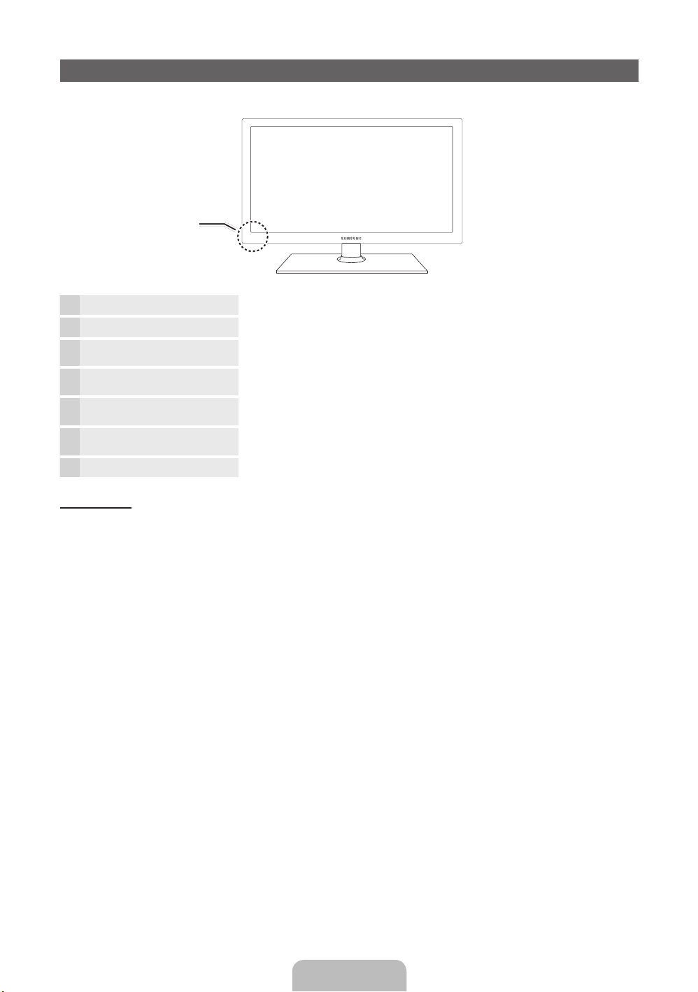
Sensor do controle remoto Aponte o controle remoto para este ponto na TV.
Indicador de energia Pisca e apaga quando a energia está ligada e acende quando está no modo de
SOURCE
MENU Exibe o menu na tela, com os controles das funções de sua TV.
y
z
P
E
(Power)
espera.
Alterna entre todas as fontes de entrada disponíveis. No menu na tela, utilize esse
botão da mesma maneira que usaria o botão ENTERE no controle remoto.
Ajusta o volume. No menu na tela, use os botões
usaria os botões ◄ e ► no controle remoto.
Muda os canais. No menu na tela, use os botões
usaria os botões ▼ e ▲ no controle remoto.
Liga e desliga a TV.
y
z
da mesma maneira que
da mesma maneira que
Modo standby
Não deixe a sua TV em standby por longos períodos (quando você viajar, por exemplo). Uma pequena quantidade de energia
é consumida mesmo com o botão Power desligado. É melhor desconectar o cabo da tomada.
Português - 4
Page 23

Como instalar o kit de montagem na parede
Instalação do kit de montagem na parede
O kit de montagem na parede (vendido separadamente) permite instalar a TV na parede.
Para obter informações detalhadas sobre como fazer a montagem na parede, consulte as instruções fornecidas juntamente
com o kit. Entre em contato com um técnico para instalar o suporte de montagem na parede. A Samsung Electronics não se
responsabiliza por qualquer dano ao produto ou ferimento a si próprio ou a outras pessoas quando você decide instalar a TV
por sua conta.
Especificações do kit de montagem na parede (VESA)
✎
O kit de montagem na parede é vendido separadamente.Instale seu suporte de parede em uma parede sólida
e perpendicular ao chão. Se a fixação for feita em algum outro material de construção, entre em contato com o
revendedor mais próximo. Se instalado em um teto ou uma parede com inclinação, ele poderá cair e ocasionar algum
dano pessoal grave.
✎
NOTA
As medidas padrão para kits de montagem na parede são mostradas na tabela abaixo.
x
Ao adquirir o nosso kit para montagem na parede, um manual de instalação detalhado e todas as peças necessárias
x
acompanham o produto.
Não use parafusos que não estejam em conformidade com as especificações VESA de parafuso padrão.
x
Não utilize parafusos mais longos que a dimensão padrão ou que não estejam em conformidade com as
x
especificações de parafusos padrão VESA. Parafusos muito longos podem danificar o interior da TV.
Para kits de montagem na parede que não estejam em conformidade com essas especificações VESA de parafuso
x
padrão, o comprimento dos parafusos pode ser diferente, dependendo das especificações dos kits.
Não aperte os parafusos com muita força, pois isso pode danificar o produto ou ocasionar sua queda, o que pode
x
resultar em ferimentos pessoais. A Samsung não se responsabiliza por esses tipos de acidentes.
A Samsung não se responsabiliza por danos ao produto nem ferimentos quando for usado um suporte para parede
x
que não seja VESA ou o especificado, ou caso o cliente não siga as instruções de instalação do produto.
Nossos modelos de 63” não estão em conformidade com as especificações VESA. Por isso, é necessário utilizar o
x
nosso kit especial de montagem na parede indicado para esses modelos.
Não instale a TV a uma inclinação maior do que 15º.
x
Sempre conte com a ajuda de duas pessoas para instalar a TV na parede.
x
Família de
Produto
PDP-TV
Tamanho
da TV em
polegadas
43~51 400 X 400
59~64 600 X 400
Especificações
dos orifícios para
parafusos VESA
(A * B) em milímetros
Pafafuso padrão Quantidade
M8 4
✎
Desaparafuse o orifício circundante antes de instalar o kit de montagem na parede.
Não instale o kit de montagem na parede enquanto a TV estiver ligada. Isso pode causar ferimentos
ocasionados por choque elétrico.
Português - 5
Page 24

Visualizando o controle remoto
✎
Este é um controle remoto especial para deficientes visuais e possui pontos em braile nos botões Power, Canal e
Volume.
Liga e desliga a TV.
Pressione para acessar canais
diretamente.
Pressione para selecionar mais canais
(digitais) transmitidos pela mesma
estacao. Por exemplo, para selecionar o
canal“54-3”, pressione “54”, depois
“-” e “3”.
Ajusta o volume.
Exibe o menu de tela principal.
que inclui Ver TV, Meu conteúdo e
Entrada.
Seleciona rapidamente funções
utilizadas com frequência.
Seleciona os itens do menu de tela e
troca os valores vistos no menu.
Volta ao menu anterior.
Botões utilizados nos menus Lista
de Canais, Gerenc. de Canais, Meu
conteúdo, etc.
Utilize esses botões nos modos
Meu conteúdo e Anynet+ (HDMI-CEC).
Exibe e seleciona as fontes de vídeo
disponíveis.
Volta ao canal anterior.
Elimina o som temporariamente.
Muda os canais.
Exibe a lista de canais na tela.
Exibe o EPG (Electronic Programme
Guide - Guia eletrônico de programas)
Exibe informações na tela da TV.
Sai do menu.
E-MANUAL: Exibe o e-Manual.
SRS: Seleciona o Modo de Som.
X: Liga ou Desliga a imagem 3D.
P.SIZE: Seleciona o Tam. Imagem.
CC: Exibe legendas digitais.
MTS: pressione para selecionar estéreo,
mono ou programa de áudio separado
(transmissão SAP).
Instalação das pilhas (Tamanho das pilhas: AAA)
✎
NOTA
Utilize o controle remoto a uma distância máxima de 7 metros
x
da TV.
Luzes brilhantes podem afetar o desempenho do controle
x
remoto. Evite utilizá-lo quando estiver perto de luzes
fluorescentes ou de letreiros de neon.
A cor e o formato podem variar, dependendo do modelo.
x
Português - 6
Page 25

Como navegar pelos menus
Antes de usar a TV, siga as etapas abaixo para aprender
como utilizar o menu para selecionar e ajustar as diferentes
funções.
1 Botão MENU: Exibe o menu de tela principal.
2 ENTER
3 Botão RETURN: Volta ao menu anterior.
4 Botão EXIT: Sai do menu na tela.
E
seleciona um item. Confirma a configuração.
/ botão de direção: Move o cursor e
Operação do menu (exibição na tela)
As etapas de acesso podem ser diferentes dependendo do
menu selecionado.
MENU As opções do menu principal são
1
2
3
4
5
6
▲ / ▼
ENTER
▲ / ▼
◄ / ►
ENTER
EXIT
e
E
E
exibidas na tela:
Imagem, Som, Canal, Rede,
Sistema e Suporte.
Selecione um ícone com o botão
▲ ou ▼.
Pressione ENTERE para acessar
o submenu.
Selecione o submenu desejado
utilizando os botões ▲ ou ▼.
Ajuste o valor de um item utilizando
os botões ◄ ou ►. As etapas
para ajuste de menu podem ser
diferentes dependendo do menu
selecionado.
Pressione ENTERE para
confirmar a seleção.
Pressione EXIT.
7
Conexão com uma antena
Quando a TV for ligada, os ajustes básicos serão realizados automaticamente.
✎
Conexão do cabo de força e da antena.
✎
O dispositivo PDP pode interferir em um rádio amador ou rádio AM.
✎
A utilização de um rádio transmissor/receptor portátil, um rádio Ham ou um rádio AM próximo à sua TV pode causar
mau funcionamento da TV.
Entrada de energia
Cabo de antena (Não fornecido)
ou
Antena VHF/UHF
Cabo
ANT OUT
Português - 7
Page 26

Ajuste - Plug & Play (Configuração inicial)
POWER
INFO GUIDE
Quando a TV for ligada, uma sequência de avisos na tela irá auxiliá-lo a realizar as configurações básicas. Pressione o botão
POWERP. Plug & Play está disponível apenas quando a Entrada está definida como TV.
✎
Antes de ligar a TV, certifique se o cabo da antena está conectado. (p. 7).
✎
Para retornar à etapa anterior, pressione o botão vermelho.
Seleção de idioma
1
Seleção de Loja ou
2
Casa
Configuração do Modo
3
Relógio.
Seleção de antena
Pressione o botão ▲ ou ▼, e então pressione o botão ENTER
Selecione o idioma desejado para o menu da tela.
Pressione o botão ◄ ou ►, e então pressione o botão ENTER
Selecione o modo Casa. O modo Loja é o modo utilizado pelas lojas.
Para retornar as configurações da unidade de Loja para Casa (padrão):
Pressione o botão de volume da TV. Ao ver o menu de volume na tela,
aperte e mantenha o botão pressionado o MENU por 5 segundos.
Se você selecionar o modo Loja, algumas funções estarão desabilitadas
para uso. Por favor selecione o modo Casa quando assistir em casa.
Configure a opção Modo Relógio automática ou manualmente.
y Auto: Configure a opção Modo Relógio automática.
y Manual: permite definir data e hora atuais manualmente.
Pressione o botão ▲ ou ▼, e então pressione o botão ENTER
E
.
E
.
E
. Selecione Ar ou Cabo.
4
Seleção de canal
5
Aproveite a sua TV!.
Pressione o botão ▲ ou ▼, e então pressione o botão ENTER
canal a memorizar. Ao configurar a fonte de antena como Cabo, será exibida uma etapa
permitindo que você atribua valores numéricos (frequências de canais) aos canais. Para
obter mais informações, consulte Canal → Prog. Automática no e-Manual.
Pressione o botão ENTER
Pressione o botão ENTER
E
quando desejar interromper o processo de memorização.
E
.
E
. Selecione a fonte de
6
Se você quiser restaurar essa função.
MENU → Sistema → Plug & Play → ENTER
O
É preciso realizar Plug & Play novamente em casa, mesmo que essa função já tenha sido utilizada na loja.
E
Português - 8
Page 27

Conexão com um dispositivo AV
Usando um cabo HDMI ou HDMI para cabo DVI: conexão HD (até 1080p)
Dispositivos disponíveis: DVD, leitor de discos Blu-ray, cabo HD, receptor de satélite HD (conversor Set-Top Box)
Dispositivo
WR
BrancoVermelho
Cabo HDMI (Não fornecido)
HDMI OUT
Dispositivo
HDMI para Cabo DVI (Não fornecido)
Cabo de áudio (Não fornecido)
✎
HDMI IN 1(DVI), 2, 3, 4 / PC/DVI AUDIO IN
Para obter uma qualidade melhor de Imagem e áudio, conecte a um dispositivo digital usando um cabo
x
HDMI.
Um cabo HDMI é compatível com sinais digitais de vídeo e áudio, e não requer um cabo de áudio.
x
– Para conectar a TV a um dispositivo digital que não seja compatível com a saída HDMI, use cabos HDMI/DVI
e de áudio.
A Imagem talvez não seja exibida normalmente (caso seja) ou o áudio poderá falhar se um dispositivo externo
x
que usa uma versão anterior do modo HDMI for conectado à TV. Se esse problema ocorrer, informe-se junto
ao fabricante do dispositivo externo sobre a versão HDMI e, se estiver desatualizada, solicite uma atualização.
Certifique-se de comprar um cabo HDMI certificado. Caso contrário, a imagem talvez não seja exibida ou
x
poderá ocorrer um erro de conexão.
Recomenda-se um cabo HDMI básico de alta velocidade ou um com ethernet. Esse produto não é compatível
x
com a função ethernet via HDMI.
Uso de um Cabo de áudio/vídeo (480i apenas) ou Componente (até 1080p)
Dispositivos disponíveis: DVD, leitor de discos Blu-ray, cabo, receptor de satélite, videocassete
DVI OUT
2
1
Adaptador
Cabo de áudio (Não
Vermelho
Branco
Vermelho Azul Verde
fornecido)
Dispositivo
✎
Ao conectar no AV IN, a cor da entrada AV IN [Y/VIDEO] (verde) não irá corresponder ao cabo de vídeo
para entrada
componente
(Fornecido)
Cabo de áudio
(Não fornecido)
Cabo de áudio
(Não fornecido)
Dispositivo
Vermelho
(amarelo).
✎
Para obter a melhor qualidade de imagem, recomenda-se a conexão Componente, em vez de A/V.
Português - 9
Branco Amarelo
Page 28

Conexão com um dispositivo de áudio
1
2
1
2
Uso de uma conexão de Cabo óptico (digital) ou Cabo áudio (analógico)
Dispositivos disponíveis: Sistema digital de áudio, Amplificador, DVD home theater
Cabo óptico (Não fornecido)
Cabo de áudio (Não fornecido)
✎
DIGITAL AUDIO OUT (OPTICAL)
Quando um sistema de áudio digital for conectado à entrada DIGITAL AUDIO OUT (OPTICAL), reduza o
x
OPTICAL
AUDIO IN
W R
R-AUDIO-L
Sistema digital de áudio
Dispositivo
volume da TV e do sistema.
Áudio 5.1 CH é possível quando a TV está conectada a um dispositivo externo que ofereça suporte a tal tecnologia.
x
Quanto o receiver (home theater) estiver ajustado em ligado), você poderá ouvir a reprodução de som pelo conector
x
óptico da TV. Quando a TV estiver recebendo um sinal de DTV, ela irá enviar som 5.1 CH ao amplificador ou DVD
home theater, vendido separadamente. Quando a fonte é um componente digital como um receptor de DVD player/
Blu-ray player/Cabo/Satélite e estiver conectada à TV via HDMI, somente será ouvido som de 2 canais do receptor
do home theater. Caso deseje ouvir áudio 5.1 CH, conecte o conector digital audio out do receptor do DVD player/
Blu-ray player/Cabo/Satélite diretamente a um Amplificador ou Home theater, e não à TV.
✎
AUDIO OUT: Conecta-se às entradas de áudio do seu amplificador/DVD home theater.
Ao fazer a conexão, use o conector apropriado.
x
Quando um amplificador de áudio estiver conectado às entradas AUDIO OUT: diminua o volume da TV e
x
ajuste o nível do volume com o controle de volume do amplificador.
Como se conectar a um PC
Usando um cabo HDMI ou HDMI para cabo DVI ou um cabo D-sub
✎
A conexão por meio do cabo HDMI talvez não seja compatível dependendo do PC.
Cabo de áudio (Não fornecido)
HDMI para cabo DVI (Não fornecido)
Cabo HDMI (Não fornecido)
Cabo de áudio (Não fornecido)
Cabo D-Sub (Não fornecido)
Português - 10
AUDIO OUT
DVI OUT
HDMI OUT
AUDIO OUT
PC OUT
Page 29

Modo de exibição (D-Sub e HDMI/DVI Entrada)
A resolução ótima é de 1920 x 1080 @ 60 Hz.
Modo Resolução
IBM
MAC
VESA DMT
VESA DMT / DTV CEA 1920 x 1080p 67.500 60.000 148.500 +/+
✎
NOTA
Para uma conexão a cabo HDMI/DVI, é necessário utilizar a entrada HDMI IN 1(DVI).
x
O modo entrelaçado não é compatível.
x
O aparelho pode operar de forma anormal se um formato de vídeo fora do padrão for selecionado.
x
Modos Separado e Composto são suportados. SOG (Sync On Green - Sincr. no verde) não é compatível.
x
640 x 350
720 x 400
640 x 480
832 x 624
1152 x 870
640 x 480
640 x 480
640 x 480
800 x 600
800 x 600
800 x 600
1024 x 768
1024 x 768
1024 x 768
1152 x 864
1280 x 1024
1280 x 1024
1280 x 800
1280 x 800
1280 x 960
1360 x 768
1440 x 900
1440 x 900
1680 x 1050
Frequência horizontal
(KHz)
31.469
31.469
35.000
49.726
68.681
31.469
37.861
37.500
37.879
48.077
46.875
48.363
56.476
60.023
67.500
63.981
79.976
49.702
62.795
60.000
47.712
55.935
70.635
65.290
Frequência vertical
(Hz)
70.086
70.087
66.667
74.551
75.062
59.940
72.809
75.000
60.317
72.188
75.000
60.004
70.069
75.029
75.000
60.020
75.025
59.810
74.934
60.000
60.015
59.887
74.984
59.954
Frequência do relógio
de pixels
(MHz)
25.175
28.322
30.240
57.284
100.000
25.175
31.500
31.500
40.000
50.000
49.500
65.000
75.000
78.750
108.000
108.000
135.000
83.500
106.500
108.000
85.500
106.500
136.750
146.250
Polaridade de
sincronização
(H / V)
+/-
-/+
-/-
-/-
-/-
-/-
-/-
-/+/+
+/+
+/+
-/-
-/+/+
+/+
+/+
+/+
-/+
-/+
+/+
+/+
-/+
-/+
-/+
Alteração da fonte de entrada
Lista de Entradas
Utilize para selecionar TV ou uma fonte de entrada externa,
como DVD / leitor de discos Blu-ray / cabo / receptor de
satelite.
■ TV / PC / AV / Component1 / Component2 / HDMI1/
DVI / HDMI2 / HDMI3 / HDMI4 /
USB / AllShare
✎
Só é possível escolher entre os
dispositivos externos que estão
conectados à TV. Na Lista de
Entradas, as entradas conectadas
serão ativadas.
✎
Na Lista de Entradas, o PC
permanece sempre ativo.
✎
Se os dispositivos externos conectados não estiverem
assinalados, pressione o botão vermelho. A TV irá
procurar os dispositivos conectados.
Português - 11
Editar Nome
Na Entrada, pressione o botão TOOLS e, em seguida,
é possível definir um nome desejado para as entradas
externas.
■ VCR / DVD / Sinal Cabo / Sinal Satélite / PVR STB
/ Receptor AV / Jogos / Filmadora / PC / DVI PC /
Dispositivos DVI / TV / IPTV / Blu-ray / HD DVD /
DMA : Nomeie o dispositivo conectado às entradas
para facilitar a seleção de sua fonte de entrada.
✎
Ao conectar um PC à porta HDMI IN 1 (DVI) com o
cabo HDMI, você deverá definir a TV para o modo PC
em Editar Nome.
✎
Ao conectar um PC à porta HDMI IN 1 (DVI) com o
cabo HDMI para DVI, você deverá definir a TV para o
modo DVI PC em Editar Nome.
✎
Ao conectar um dispositivo AV à porta HDMI IN 1 (DVI)
com o cabo HDMI para DVI, você deverá definir a TV
para o modo Dispositivos DVI em Editar Nome.
NOTA
Você pode ver mais informações sobre o dispositivo externo
selecionado.
Page 30

Conexão de rede
Conexão de rede - Sem fio
Você pode conectar sua TV à Rede por meio de um roteador sem fio ou modem padrão. Para conectar sua TV a uma
rede sem fio, será necessário um roteador ou modem sem fio e um Adaptador de rede sem fio Samsung (WIS09ABGN,
WIS09ABGN2,WIS10ABGN), que você deve conectar à entrada USB no painel lateral ou traseiro de sua TV.
Painel traseiro da TV
Porta de Rede na parede
Cabo de rede (Não fornecido)
O adaptador de rede sem fio Samsung é vendido separadamente e é oferecido por revendedores e sites de vendas seletos
e pelo site Samsungparts.com. O adaptador de rede sem fio Samsung é compatível com os protocolos de comunicação
IEEE 802.11A/B/G e N. A Samsung recomenda a utilização do IEEE 802.11N. Ao reproduzir o vídeo em uma conexão IEEE
802.11B/G, o vídeo pode não ser reproduzido com fluidez.
A maioria dos sistemas de rede sem fio incorpora um sistema de segurança que exige que os dispositivos que acessam a
rede por meio de um ponto de acesso ou roteador sem fio (normalmente um Compartilhador de IP sem fio) transmitam um
código de segurança criptografado chamado chave de acesso. Se o modo Transmissão elevada Pura (Ambiente intacto)
802.11n for selecionado e o tipo de criptografia for configurado como WEP, TKIP ou TKIPAES (WPS2Mixed) para seu
ponto de acesso, as TVs Samsung não serão compatíveis com uma conexão que esteja em conformidade com as novas
especificações da certificação de Wi-Fi.
Configuração da conexão de rede - Sem fio
As instruções abaixo são para redes que utilizam o Dynamic Host Configuration Protocol (DHCP - Protocolo de configuração
dinâmica de hosts) para configurar conexões de rede. Se você tiver uma rede de IP estático, consulte o manual do usuário
para encontrar as instruções de configuração. Para configurar sua conexão de rede para uma rede que utiliza DHCP, siga
estas etapas:
1. Conecte a TV à sua rede, como mostrado nas ilustrações acima.
2. Ligue a sua TV, pressione o botão MENU no seu controle remoto, e selecione Rede → Configurações de rede.
3. Selecione Sem fio.
4. Quando terminar, será exibida uma lista com as redes disponíveis.
5. Na lista de redes, pressione o botão ▲ ou ▼ para selecionar uma rede e, em seguida, pressione o botão Next.
6 If the AP has security, enter the Security key (Security or PIN), and then select Avançar.
✎
Ao inserir a Chave seg (Segurança ou Senha), use os botões ▲/▼/◄/► no seu controle remoto para selecionar
número/caracteres.
7 A tela de teste da rede é exibida e a configuração da rede é realizada.
✎
Para obter mais informações, consulte “Conexões de rede” no e-Manual.
Compartilhador de IP sem fio
(com o servidor DHCP)
ou
Adaptador de rede
sem fio Samsung
Português - 12
Page 31

Conexão de rede - Cabo
Há duas maneiras principais para conectar sua TV à rede usando o cabo, dependendo da configuração da rede. Elas estão
ilustradas abaixo:
Porta do modem na parede
Porta do modem na parede
✎
Uma velocidade de rede menor que 10 Mbps não é compatível.
Configuração da conexão de rede - Cabo
A maioria das redes domésticas utiliza o Dynamic Host Configuration Protocol (DHCP - Protocolo de configuração dinâmica
de hosts) para configurar conexões de rede. Redes domésticas compatíveis com DHCP fornecem automaticamente os
valores de endereço IP, máscara de sub-rede, gateway e DNS de que sua TV necessita para acessar a Internet, fazendo com
que você não precise digitá-los manualmente.
Para configurar sua conexão de rede para uma rede que utiliza DHCP, siga estas etapas:
1. Conecte a TV à sua rede, como mostrado em uma das ilustrações acima.
2. Ligue a sua TV, pressione o botão MENU no seu controle remoto e selecione Rede → Configurações de rede. A tela
Configurações de Rede será exibida.
3. Selecione Cabo.
✎
Algumas redes são redes de IP estático. Se a sua for uma rede de IP estático, não será possível usar o DHCP
para configurar a conexão de rede. Nesse caso, será necessário digitar manualmente os valores de endereço IP,
máscara de sub-rede, gateway e servidor DNS.
✎
Para obter mais informações, consulte “Conexão de rede a cabo” no e-Manual.
Modem externo
(ADSL / VDSL / TV a cabo)
Cabo de rede (Não fornecido)Cabo do modem (Não fornecido)
Cabo de rede (Não fornecido)
Painel traseiro da TV
Painel traseiro da TV
Português - 13
Page 32

Como visualizar o e-Manual
E-MANUAL
É possível ler a introdução e as instruções a respeito dos recursos de TV
armazenados em sua TV.
TV.
Exibição na tela
Tela da TV: Vídeo, programa de TV,
entre outros, exibidos no momento.
MENUm → Suporte → e-Manual → ENTER
O
✎
Para retornar ao menu principal do e-Manual, pressione o botão E-MANUAL.
E
Altera a categoria. Pressione o
FUNÇÕES BÁSICAS
Como alterar o modo de Imagem prede nido
Ajuste de con gurações de Imagem
Como alterar as Tam. Imagem
Como alterar as opções de imagem
Ajuste da TV com o seu PC
}
Índice E Entrar e Sair
botão l ou r para selecionar a
categoria desejada.
Exibe a lista do submenu.
Pressione o botão ENTER
selecionar o submenu desejado.
Botões de operação:
}
Azul (Índice): Exibe a tela do índice remissivo.
E
Entrar: Seleciona uma categoria ou submenu.
e
Sair: Sai do e-Manual.
E
para
Como alternar entre o e-Manual e o(s) menu(s) correspondente(s).
FUNÇÕES BÁSICAS > Alteração do modo de imagem prede nido (5/10)
Alteração do modo de imagem predefi nido
O MENUm → Imagem → Modo de Imagem → ENTER
■
Modo de Imagem
Selecione o seu tipo de imagem preferido.
• Dinâmico: Adequado para uma sala bem iluminada.
• padrão: Adequado para um ambiente normal.
• fi lme: Adequado para assistir fi lmes em uma sala escura.
• Entretenimento: Adequado para assistir fi lmes e jogos.
N Está disponível apenas no modo PC.
a
Exp. Agora b Residência { Zoom } Índice L Página e Sair
E
Tentar Agora
E-MANUAL
Método 1 Método 2
1. Pressione o botão vermelho para selecionar Exp. Agora
se quiser executar o(s) menu(s) correspondente(s).
2. Para retornar à tela do e-Manual, pressione o botão
E-MANUAL.
1. Pressione o botão ENTER
de conteúdos. A mensagem “Você deseja executar
isso?” é exibida. Selecione Sim e pressione o botão
ENTERE. A janela OSD será exibida.
2. Para retornar à tela do e-Manual, pressione o botão
E-MANUAL.
Imagem
Modo de Imagem
Luz da Célula : 10
Contraste : 100
Brilho : 45
Nitidez : 50
Cor : 50
Matiz (Vd/Vm) : Vd50/Vm50
Ajuste da tela
E
ao selecionar a área
: Normal
r
Português - 14
Page 33

Visualização de conteúdos
FUNÇÕES BÁSICAS > Alteração do modo de imagem predenido (5/10)
Alteração do modo de imagem predefinido
O MENUm → Imagem → Modo de Imagem → ENTER
■
Modo de Imagem
Selecione o seu tipo de imagem preferido.
• Dinâmico: Adequado para uma sala bem iluminada.
• padrão: Adequado para um ambiente normal.
• filme: Adequado para assistir filmes em uma sala escura.
• Entretenimento: Adequado para assistir filmes e jogos.
N Está disponível apenas no modo PC.
a
Exp. Agora b Residência { Zoom } Índice L Página e Sair
Botões de operação:
a
Vermelho (Tentar Agora): Exibe o(s) menu(s) correspondente(s).
b
Verde (Residência): Direciona para a tela inicial do e-Manual.
{
Amarelo (Zoom): Amplia a tela.
}
Azul (Índice): Exibe a tela do índice remissivo.
L
(Página): Mova-se para a página anterior ou seguinte.
Utilização do modo de zoom
Quando visualizar a página de instruções do e-Manual,
pressione o botão amarelo para ampliar a tela. É possível
percorrer a tela ampliada usando os botões
✎
Para retornar à tela anterior, pressione o botão
u
ou d.
RETURN.
E
Área de conteúdos: Será possível visualizar
os conteúdos correspondentes se você tiver
selecionado um submenu. Para ir para a página
anterior ou para a próxima página, pressione o
botão l ou r.
Alteração do modo de imagem predefinido
O MENUm → Imagem → Modo de Imagem → ENTER
■
Modo de Imagem
No modo PC, é possível selecionar somente Entretenimento e Padrão.
• Dinâmico: Adequado para uma sala bem iluminada.
• padrão: Adequado para um ambiente normal.
• filme: Adequado para assistir filmes em uma sala escura.
• Entretenimento: Adequado para assistir filmes e jogos.
N Está disponível apenas no modo PC.
E
Como pesquisar uma palavra-chave usando a página do índice remissivo
✎
Esta função pode não ser suportada, dependendo do idioma.
1. Se você quiser pesquisar uma palavra-chave, pressione o botão azul para abrir a tela Índice.
l
2. Pressione o botão
3. Pressione o botão
ou r para selecionar a ordem de caracteres desejada e pressione o botão ENTERE.
u
ou d para selecionar uma palavra-chave que deseja ver e pressione o botão ENTERE.
4. É possível visualizar a tela de instruções correspondente do e-Manual.
✎
Para fechar a tela Índice, aperte o botão RETURN.
U
Mover
R
Retornar
Português - 15
Page 34

Solução de problemas
Se a TV aparentar ter algum problema, primeiro verifique esta lista de possíveis problemas e solucões. Se nenhuma dessas
dicas de solução de problemas se aplicar ao seu caso, visite o site “www.samsung.com” e clique em Suporte, ou entre em
contato com o centro de atendimento ao cliente Samsung.
Problemas Soluções e explicações
A TV não liga. • Certifique-se de que o cabo de alimentação CA esteja conectado corretamente à tomada da parede
Não há imagem / vídeo. • Verifique as conexões de cabos (retire e reconecte todos os cabos conectados à TV e aos
O controle remoto não funciona. • Troque as pilhas do controle remoto com os pólos (+/-) nas direções corretas.
O controle remoto do decodificador de TV
a cabo / receptor não liga ou desliga a TV
e nem ajusta seu volume.
✎
Algumas das imagens e funcoes acima estao disponiveis apenas para modelos especificos.
✎
Você pode manter sua TV em uma condição ideal se atualizar o firmware mais recente no site (samsung.com →
Suporte → Downloads) por meio de USB.
e na TV.
• Certifique-se de que a tomada de parede esteja funcionando.
• Experimente apertar o botão POWER na TV para se certificar de que o problema não seja o controle
remoto. Caso a TV ligue, consulte a seção “O controle remoto não funciona”, localizada mais abaixo.
dispositivos externos).
• Defina as saídas de vídeo de seus dispositivos externos (Decodificador / Receptor de satélite, DVD,
Blu-ray, etc.) de modo compatível com as conexões de entrada da TV. Por exemplo, caso a saída de
um dispositivo externo seja HDMI, ela deve ser conectada a uma entrada HDMI da TV.
• Certifique-se de que seus dispositivos conectados estejam ligados.
• Certifique-se de selecionar a fonte correta da TV, pressionando o botão SOURCE no controle
remoto.
• Reinicie o dispositivo conectado, reconectando o cabo de alimentação do dispositivo.
• Limpe a janela de transmissão do sensor do controle remoto.
• Tente apontar o controle remoto diretamente para a TV, cerca de 1,5 m.
• Programe o controle remoto do decodificador / receptor para operar a TV. Consulte o manual do
usuário do decodificador / receptor de satélite para obter o código da TV SAMSUNG.
Licença
Lista de funções
y Excelente rede de comunicação e interface digital: Com um sintonizador digital de HD interno, as transmissões HD sem
assinatura podem ser visualizadas sem cabo/receptor de satélite (conversor Set-Top Box).
y 3D: Este novo recurso empolgante permite a exibição do conteúdo 3D.
y AllShare™: AllShare™ conecta sua TV e os celulares/dispositivos Samsung compatíveis por meio de uma rede.
y Anynet+(HDMI-CEC): Permite que você controle todos os dispositivos Samsung conectados que suportam anynet+ com
o controle remoto da sua TV Samsung.
y Meu conteúdo: Possibilita a reprodução de arquivos de música, fotos e filmes salvos em um dispositivo USB.
Português - 16
Page 35

Fixando a TV à Parede
Cuidado: puxar, empurrar ou subir na TV pode fazer com que ela caia. Fique atento para que as
crianças não subam ou mexam na TV, pois a TV poderá cair e causar ferimentos graves, podendo até
levar à morte. Siga todas as precauções de segurança fornecidas no folheto de segurança incluso. Para
maior estabilidade, instale um dispositivo antiqueda para fins de segurança.
Para evitar que a TV caia
1. Coloque os parafusos em grampos e prenda-os na parede firmemente.
Verifique se os parafusos estão bem presos à parede.
✎
Você pode precisar de material extra, como um chumbador,
dependendo do tipo de parede.
✎
Como os grampos, parafusos e corda necessários não são
fornecidos, você deve comprá-los separadamente.
2. Remova os parafusos da parte central traseira da TV, coloque-os em
grampos e, em seguida, aperte-os novamente na TV.
✎
Os parafusos podem não ser fornecidos com o produto. Neste
caso, adquira parafusos com as especificações a seguir.
3 Conecte os grampos fixados na TV e os que estão fixados na parede
com um cabo forte e prenda-os bem.
✎
NOTA
•
Instale a TV próxima à parede para que ela não caia para trás.
•
É seguro conectar a corda para que os grampos fixados na
parede fiquem no mesmo nível ou abaixo dos grampos fixados
na TV.
•
Desamarre a corda antes de mover a TV.
4 Verifique se todas as conexões estão seguras. Verifique periodicamente
as conexões para evitar qualquer sinal de insuficiência ou falha. Caso haja alguma dúvida sobre a segurança das
conexões, entre em contato com um profissional de instalação.
wall
Armazenamento e manutenção
✎
Se colar autocolantes na tela da TV, podem ficar algumas marcas depois de removê-los. Limpe a tela para assistir à TV.
Não borrife água nem aplique um agente de limpeza
diretamente no produto. Qualquer líquido que entre em
contato com o produto poderá provocar falha, incêndio ou
choque elétrico.
Limpe o produto utilizando um plano macio molhado com
uma pequena quantidade de água.
Português - 17
Page 36

Especificações
Considerações ambientais
Temperatura de funcionamento
Umidade operacional
Temperatura de armazenamento
Umidade de armazenamento
Rotação da base (esquerda / direita) -20˚ ~ 20˚
Nome modelo PL51D550 PL64D550
Tamanho da tela Classe 51"
Consumo de energia
Operação normal
Standby
Som
(Saída) 10 W X 2 15W x 2
Dimensões (CxLxA)
Corpo
Com suporte
Peso
Sem suporte
Com suporte
Display Resolution 1920 x 1080
✎
O design e especificações estão sujeitas a alteração sem aviso prévio.
✎
Para informações sobre fornecimento de energia, e mais informações sobre consumo de energia, consulte a etiqueta
(50.7 medidas diagonalmente)
350W
<1W
47.1 X 2.2 X 28.2 polegadas
(1196.8 X 57.0 X 715.6 mm)
47.1 X 12.0 X 31.0 polegadas
(1196.8 X 305.0 X 787.3 mm)
34.5 kg (76.1 lbs)
40.6 kg (89.5 lbs)
anexa ao produto.
50°F a 104°F (10 °C a 40 °C)
10 a 80%, sem condensação
-20 °C a 45 °C (-4°F a 113°F)
5 a 95%, sem condensação
Classe 64"
(64.0" medidas diagonalmente)
470W
<1W
58.6 x 2.2 x 34.8 polegadas
(1488.8 X 57.0 X 885.8 mm)
58.6 x 13.2 x 37.8 polegadas
(1488.8 x 335.0 x 960.2 mm)
21.8 kg (48.1 lbs)
26.1 kg (57.5 lbs)
Português - 18
Page 37

This page is intentionally
left blank.
 Loading...