

Samsung PL43E400U1F Service Manual

PlasmaTV
ChassisF5CA
ModelCodePL43E400U1FXZP
SERVICE
MANUAL
PlasmaTV
PL43E400U1F
Contents
1.Precaution
2.ProductSpecication
3.DisassemblyandReassembly
4.Troubleshooting
5.WiringDiagram
RefertotheservicemanualintheGSPN(seetherearcover)formoreinformation.

Contents
Contents
1.Precaution........................................................................................................................................1−1
1.1.SafetyPrecautions...................................................................................................................1−1
1.2.ServicingPrecautions...............................................................................................................1−3
1.3.StaticElectricityPrecautions......................................................................................................1−4
1.4.InstallationPrecautions.............................................................................................................1−5
2.ProductSpecication.........................................................................................................................2−1
2.1.ModelComparison...................................................................................................................2−1
2.2.Feature&Specications...........................................................................................................2−2
2.3.SpecicationsAnalysis.............................................................................................................2−4
2.4.Accessories............................................................................................................................2−6
2.4.1.SuppliedAccessories...................................................................................................2−6
2.4.2.SoldSeparately...........................................................................................................2−7
3.DisassemblyandReassembly..............................................................................................................3−1
3.1.OverallDisassemblyandReassembly..........................................................................................3−1
3.1.1.MethodforDisassemblyofFunctionAssy.......................................................................3−3
4.Troubleshooting................................................................................................................................4−1
4.1.Troubleshooting......................................................................................................................4−1
4.1.1.FirstChecklistforTroubleshooting.................................................................................4−1
4.1.2.CheckpointsbyErrorMode...........................................................................................4−2
4.1.3.AnalogPartTroubleshooting.........................................................................................4−7
4.1.4.DigitalPartTroubleshooting..........................................................................................4−9
4.1.5.FaultsandCorrectiveActions........................................................................................4−11
4.1.6.OperatingLogicLED...................................................................................................4−13
4.1.7.AdjustSMPSV oltagewhenchangeSMPS.......................................................................4−14
4.2.FactoryModeAdjustments........................................................................................................4−15
4.2.1.EnteringFactoryMode.................................................................................................4−15
4.2.2.FactoryData...............................................................................................................4−17
4.3.ServiceAdjustment..................................................................................................................4−40
4.4.SoftwareUpgrade....................................................................................................................4−43
5.WiringDiagram................................................................................................................................5−1
5.1.OverallWiring........................................................................................................................5−1
5.1.1.PinConnection...........................................................................................................5−2
iCopyright©1995-2012SAMSUNG.Allrightsreserved.

1.Precaution
1.Precaution
Toavoidpossibledamage,electricshocksorexposuretoradiation,followtheinstructionsbelowwithregardtosafety,
installation,serviceandESD.
1.1.SafetyPrecautions
1)Makesureallprotectivedevicesareproperlyinstalledincludingnon-metallichandlesandcompartmentcoverswhen
installingorre-installingthechassisorchassisassemblies.
2)Makesurethatnogapsexistbetweenthecabinetsforchildrentoinserttheirngersintopreventchildrenfrom
receivingelectricshocks.GapsmentionedaboveincludeventilationholesofatoogreatmagnitudebetweenthePDP
moduleandthecabinetmask,andtheimproperinstallationoftherearcabinet.
Errorsmayoccurwhentheresistanceisbelow1.0MΩorover5.2MΩ.Inthesecases,makesurethatthedeviceis
repairedbeforesendingitbacktothecustomer.
3)CheckforElectricityLeakage(ACLeakageT est)
WARNING
Donotuseaninsulatedtransformerforcheckingtheleakage.Useonlythosecurrentleakagetestersormirroring
systemsthatcomplywithANSIC101.1andtheUnderwriterLaboratory’sspecications(UL1410,59.7).
DEVICE
UNDER
TEST
LEAKAGE
CURREN T
TESTER
TES T ALL
EXPOSED ME TAL
SUR FACES
2-WIRE CORD
ALSO TES T WITH
PLUG REVERSED
(USING AC
ADAPTER PLUG
AS REQU IRED)
EARTH
GRO UND
( R E A D I N G
SHOULD NOT BE
ABOVE 0.5mA)
Figure1.1ACLeakageT est
4)Ahighvoltageismaintainedwithinthespeciedlimitsusingsafetyparts,calibrationandtolerances.Whenvoltage
exceedsthespeciedlimits,checkeachspecialpart.
5)W arningforEngineeringChanges:
Nevermakeanychangesoradditionstothecircuitdesignortheinternalpartforthisproduct.
Ex:Donotaddanyaudioorvideoaccessoryconnectors.Thismightcausephysicaldamage.
Furthermore,anychangesoradditionstotheoriginaldesign/engineeringwillinvalidatethewarranty.
6)W arning-HotChassis:
SomeTVchassisaredirectlyconnectedtooneendoftheACpowercordforelectricalreasons.Withoutinsulated
transformers,theproductcanonlyberepairedsafelywhenthechassisisconnectedtotheearthedendoftheAC
powersource.
TomakesuretheACpowercordisproperlyconnected,followtheinstructionsbelow.Usethevoltmetertomeasurethe
voltagebetweenthechassisandtheearthedground.Ifthemeasurementisover1.0V ,unplugtheACpowercordand
changethepolaritybeforereinsertingit.Measurethevoltagebetweenthechassisandthegroundagain.
Copyright©1995-2012SAMSUNG.Allrightsreserved.1-1

1.Precaution
7)SomeTVchassisareshippedwithanadditionalsecondarygroundingsystem.Thesecondarysystemisadjacentto
theACpowerline.Thesetwogroundingsystemsareseparatedinthecircuitusinganunbreakable/unchangeable
insulationmaterial.
8)Whenanyparts,materialorwiringappearoverheatedordamaged,replacethemwithnewregularonesimmediately.
Whenanydamageoroverheatingisdetected,correctthisimmediatelyandmakearegularcheckofpossibleerrors.
9)Checkfortheoriginalshapeofthelead,especiallythatoftheantennawiring,anysharpedges,theACpowerandthe
highvoltagepower.Carefullycheckifthewiringistootight,incorrectlyplacedorloose.Neverchangethespace
betweenthepartandtheprintedcircuitboard.ChecktheACpowercordforpossibledamages.Keepthepartorthe
leadawayfromanyheat-emittingmaterials.
10)SafetyIndication:
Someelectricalcircuitsordevicerelatedmaterialsrequirespecialattentiontotheirsafetyfeatures,whichcannotbe
viewedbythenakedeye.Ifanoriginalpartisreplacedwithanotherirregularone,thesafetyorprotectivefeatureswill
belostevenifthenewonehasahighervoltageormorewatts.
Criticalsafetypartsshouldbebracketedwith(
,).Useonlyregularpartsforreplacements(inparticular,ame
resistanceanddielectricstrengthspecications).Irregularpartsormaterialsmaycauseelectricshockorre.
1-2Copyright©1995-2012SAMSUNG.Allrightsreserved.

1.Precaution
1.2.ServicingPrecautions
WARNING
1)Firstcarefullyreadthe“SafetyInstruction”inthisservicemanual.
Whenthereisaconictbetweentheserviceandthesafetyinstructions,followthesafetyinstructionatalltimes.
2)Anyelectrolyticcapacitorwiththewrongpolaritywillexplode.
1)Theserviceinstructionsareprintedonthecabinet,andshouldbefollowedbyanyservicepersonnel.
2)MakesuretounplugtheACpowercordfromthepowersourcebeforestartinganyrepairs.
a)Removeorre-installpartsorassemblies.
b)Disconnecttheelectricplugorconnector,ifany.
c)Connectthetestpartinparallelwiththeelectrolyticcapacitor.
3)Somepartsareplacedatahigherpositionthantheprintedboard.Insulatedtubesortapesareusedforthispurpose.
Theinternalwiringisclampedusingbucklestoavoidcontactwithheatemittingparts.Thesepartsareinstalledback
totheiroriginalposition.
4)Aftertherepair,makesuretocheckifthescrews,partsorcablesareproperlyinstalled.Makesurenodamageiscaused
totherepairedpartanditssurroundings.
5)CheckforinsulationbetweenthebladeoftheACplugandthatofanyconductivematerials(i.e.themetalpanel,
inputterminal,earphonejack,etc).
6)InsulationCheckProcess:
UnplugthepowercordfromtheACsourceandturntheswitchon.Connecttheinsulatingresistancemeter(500V)to
theACplugblade.TheinsulatingresistancebetweenthebladeoftheACplugandthatoftheconductivematerial
shouldbemorethan1MΩ.
7)AnyB+interlockshouldnotbedamaged.
Ifthemetalheatsinkisnotproperlyinstalled,noconnectiontotheACpowershouldbemade.
8)Makesurethegroundingleadofthetesterisconnectedtothechassisgroundbeforeconnectingtothepositivelead.
Thegroundleadofthetestershouldberemovedlast.
9)Bewareofrisksofanycurrentleakagecomingintocontactwiththehigh-capacitycapacitor.
10)Thesharpedgesofthemetalmaterialmaycausephysicaldamage,soprotectyourselfbywearingglovesduringthe
repair.
11)Duetothenatureofplasmadisplaypanels,partialafter-imagesmayappearifastillpictureisdisplayedonthescreen
foralongperiodoftime.
Thisiscausedbybrightnessdeteriorationduetothestorageeffectofthepanel,andtopreventthisfromhappening,we
recommendthatthebrightnessandcontrastarereduced.(e.g.)Contrast:25,Brightness:50
Copyright©1995-2012SAMSUNG.Allrightsreserved.1-3

1.Precaution
1.3.StaticElectricityPrecautions
1)Somesemi-conductive(“solidstate”)devicesarevulnerabletostaticelectricity .ThesedevicesareknownasESD.
ESDincludestheintegratedcircuitandtheeldeffecttransistor.Toavoidanymaterialsdamagefromelectrostatic
shock,followtheinstructionsdescribedbelow.
2)Removeanystaticelectricityfromyourbodybyconnectingtheearthgroundbeforehandlinganysemi-conductiveparts
orassemblies.Alternatively ,wearadischargeablewrist-belt.
(Makesuretoremoveanystaticelectricitybeforeconnectingthepowersource-thisisasafetyinstructionfor
avoidingelectricshock)
3)RemovetheESDassemblyandplaceitonaconductivesurfacesuchasaluminumfoiltopreventaccumulatingstatic
electricity.
4)DonotuseanyFreon-basedchemicals.SuchchemicalswillgeneratestaticelectricitythatcausesdamagetotheESD.
5)Useonlygrounded-tipironsforsolderingpurposes.
6)Useonlyanti-staticsolderremovaldevices.
Mostsolderremovaldevicesdonotsupportananti-staticfeature.Asolderremovaldevicewithoutananti-staticfeature
canstoreenoughstaticelectricitytocausedamagetotheESD.
7)DonotremovetheESDfromtheprotectiveboxuntilthereplacementisready.MostESDreplacementsarecoveredwith
lead,whichwillcauseashorttotheentireunitduetotheconductivefoam,aluminumfoilorotherconductivematerials.
8)RemovetheprotectivematerialfromtheESDreplacementleadimmediatelyafterconnectingittothechassisor
circuitassembly.
9)T akeextremecautioninhandlinganyuncoveredESDreplacements.Actionssuchasbrushingclothesorliftingyourleg
fromthecarpetoorcangenerateenoughstaticelectricitytodamagetheESD.
CAUTION
Theseservicinginstructionsareforusebyqualiedservicepersonnelonly.
Toreducetheriskofelectricshockdonotperformanyservicingotherthanthatcontainedintheoperatinginstructions
unlessyouarequaliedtodoso.
1-4Copyright©1995-2012SAMSUNG.Allrightsreserved.

1.Precaution
1.4.InstallationPrecautions
1)Forsafetyreasonsaminimumoftwopeoplearerequiredtocarrythisproduct.
2)Keepthepowercordawayfromanyheatemittingdevices,asameltedcoveringmaycausereorelectricshock.
3)Donotplacetheproductinareaswithpoorventilationsuchasabookshelforcloset.Theincreasedinternaltemperature
maycausere.
4)Bendtheexternalantennacablewhenconnectingittotheproduct.Thisisameasuretoprotectitfrombeingexposedto
moisture.Otherwise,itmaycauseareorelectricshock.
5)Makesuretoturnthepoweroffandunplugthepowercordfromtheoutletbeforerepositioningtheproduct.Also
checktheantennacableortheexternalconnectorsiftheyarefullyunplugged.Damagetothecordmaycausere
orelectricshock.
6)Keeptheantennafarawayfromanyhigh-voltagecablesandinstallitrmly .Contactwiththehigh-voltagecableorthe
antennafallingovermaycausereorelectricshock.
7)WhenconnectingtheRFantenna,checkforaDTVreceivingsystemandinstallaseparateDTVreceptionantennafor
areaswithnoDTVsignal.
8)Wheninstallingtheproduct,leaveenoughspace(4”)betweentheproductandthewallforventilationpurposes.A
riseintemperaturewithintheproductmaycausere.
9)WhenmovingaPDPwithremovablespeakers,detachthespeakersrstbeforemovingthemainbody.MovingthePDP
mainbodywithoutseparatingthespeakersmaycausethespeakerstodetach,possiblycausingdamageorinjury .
Copyright©1995-2012SAMSUNG.Allrightsreserved.1-5

2.ProductSpecication
2.ProductSpecication
2.1.ModelComparison
InchPN43E400
FrontView
FrontColorSteamMold
WithoutStand1011.8x622.4x56.0mm Dimensions
WxDxH
(inch)
43"
WithStand
1011.8x675.9x262.0mm
WithoutStand16.0kg
Weight
(lbs)
43"
WithStand19.0kg
FeatureZeroBlackPanel/ConnectShare
2-1Copyright©1995-2012SAMSUNG.Allrightsreserved.
2.ProductSpecication
2.2.Feature&Specications
■Features
•Digital-TV ,RF,2-HDMI,1-Component(A V),1-USB2.0,Optical
•Brightness:1500cd/m2
•ContrastRatio:1000000:1
•AllShare,Content
ModelPx43E400
PDPPanelClearImagePanel
ScanningFrequency
Horizontal:60kHz~73kHz(Automatic)
Vertical:47Hz~63Hz(Automatic)
DisplayColors16.7Mcolor
Maximumresolution
Horizontal:1920Pixels
Vertical:1080Pixels
InputSignalAnalog0.7Vp-p±5%positiveat75Ω,internallyterminated
InputSyncSignalH/VSeparate,TTL,P .orN.
MaximumPixelClockrate74.25MHz
ACPowerV oltage&FrequencyAC110V~120V ,60Hz
PowerConsumption205W
TVSystem
Tuning:FrequencySynthesize(Refertodetailed
FrequencyTable)
System:ATSC&ClearQAM
Sound:NTSC-M,DolbyDigital+
EnvironmentalConsiderations
OperatingTemperature:32˚F~122˚F(0˚C~50˚C)
OperatingHumidity:20%~90%
StorageTemperature:-4˚F~140˚F(-20˚C~60˚C)
StorageHumidity:10%~90%
AudioSpec.
MAXInternalAudioOutputPower:Each3W(Left/Right)
Equalizer:5band
OutputFrequency:RF:20Hz~15.4kHz
A V/Componet/HDMI:20Hz~20kHz
Copyright©1995-2012SAMSUNG.Allrightsreserved.2-2

2.ProductSpecication
■43”Specication
ModelPx43E450xxxxxxPx43E400xxxxxx
WithStand39.8x26.6x12inches39.8x26.6x12inches
Dimensions
(WxHxD)
WithoutStand39.8x24.5x2.2inches39.8x24.5x2.2inches
WithStand41.8lbs41.8lbs
Weight
WithoutStand35.2lbs35.2lbs
ScreenSize43Inches(16:9)43Inches(16:9)
PCResolution1920(H)x1080(V)
PowerConsumption43HD:200W±10%andLess43HD:200W±10%andLess
AntennaInputANT-AIR/CABLEIN75Ωunbalanced
VideoInput
A V
COMPONENT1:
480i/480p/720p/1080i/1080p
PC
HDMI1:480p/720p/1080i/1080p
HDMI2(DVICompatible):
480p/720p/1080i/1080p
A V
COMPONENT1:
480i/480p/720p/1080i/1080p
HDMI1:480p/720p/1080i/1080p
HDMI2:480p/720p/1080i/1080p
AudioInput
A V
COMPONENT1:
480i/480p/720p/1080i/1080p
DVI
A V
COMPONENT1:
480i/480p/720p/1080i/1080p
DVI
AudioOutputAUDIO(L/R)
SpeakerOutput10W+10W(40dB+40dB)
NewFeaturesZeroBlackPanel/ConnectShareZeroBlackPanel/ConnectShare
2-3Copyright©1995-2012SAMSUNG.Allrightsreserved.

2.ProductSpecication
2.3.SpecicationsAnalysis
ModelPx43E450xxxxxxPx43E400xxxxxx
Design
DisplayT ypePDPTVPDPTV
Buil-InT unerOO
Resolution1024x768852x480
PDPModuleEHEV
ScreenSize43inches43inches
Basic
PictureRatio16:916:9
Brightness1,500Cd/m21,500Cd/m2
ContrastRatio10000:110000:1 Picture
PictureEnhancerDNIe(SEMS23)DNIe(SEMS23)
Equalizer5Band5Band
AutoV olumeControlOO
SurroundSoundSRSTheaterSoundSRSTheaterSound
Audio
SpeakerOutput10W+10W10W+10W
PIPXO
DoubleScreenXX
CaptionOO
StillImageXX
EPGOO
MyColorControlXX
EnergySavingOO
ScreenBurnProtectionOO
Features
AnynetXX
Antenna1(Cable/Air)1(Cable/Air)
A VInput1Input1Input
S-VideoXX
Component
W/W:1Input
EU/CIS:1Input
W/W:1Input
EU/CIS:1Input
PC(D-SUB)1InputX
DVI1Input1Input
HDMIE450–2InputE400–2Input
USB11
Connections
Copyright©1995-2012SAMSUNG.Allrightsreserved.2-4

2.ProductSpecication
SubWooferXX
Optical1X
ETCSpeaker/StandBuilt-inSpeakerBuilt-inSpeaker
TIP
O:Supported,X:NotSupported
NOTE
Forthepowersupplyandpowerconsumption,refertothelabelattachedtotheproduct.
2-5Copyright©1995-2012SAMSUNG.Allrightsreserved.
2.ProductSpecication
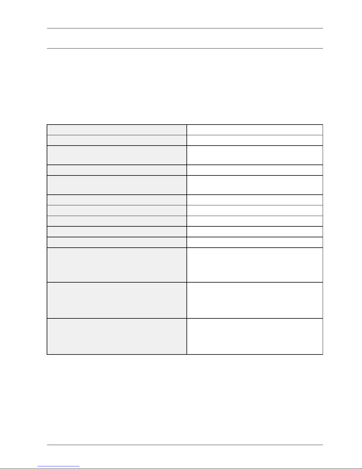
2.4.Accessories
2.4.1.SuppliedAccessories
AccessoriesItemItemcodeRemark
PowerCord3903-000467
Batteries(AAAx2)4301-000121
A B C D
P.MODE P.S IZE
SRS
MEDIA.P
HDMI
RemoteControlAA59-00600A
CleaningClothBN63-02368B
Owner`sInstructionsBN68-04404A
SamsungServiceCenter
Copyright©1995-2012SAMSUNG.Allrightsreserved.2-6

2.ProductSpecication
2.4.2.SoldSeparately
AccessoriesItemItemcodeRemark
RS232Cable-
HDMI-
HDMI-DVI-
Audio-
Component-
Composite(A V)-
Coaxial(RF)-
SamsungServiceCenter
2-7Copyright©1995-2012SAMSUNG.Allrightsreserved.
3.DisassemblyandReassembly
3.DisassemblyandReassembly
ThissectionoftheservicemanualdescribesthedisassemblyandreassemblyproceduresforthePDPTV .
WARNING
ThisPDPTVcontainselectrostaticallysensitivedevices.Usecautionwhenhandlingthesecomponents.
3.1.OverallDisassemblyandReassembly
CAUTION
•DisconnectthePDPTVfromthepowersourcebeforedisassembly.
•Followthesedirectionscarefully;neverusemetalinstrumentstopryapartthecabinet.
•Ifthereisnoadditionalcomment,itissameforallinches.
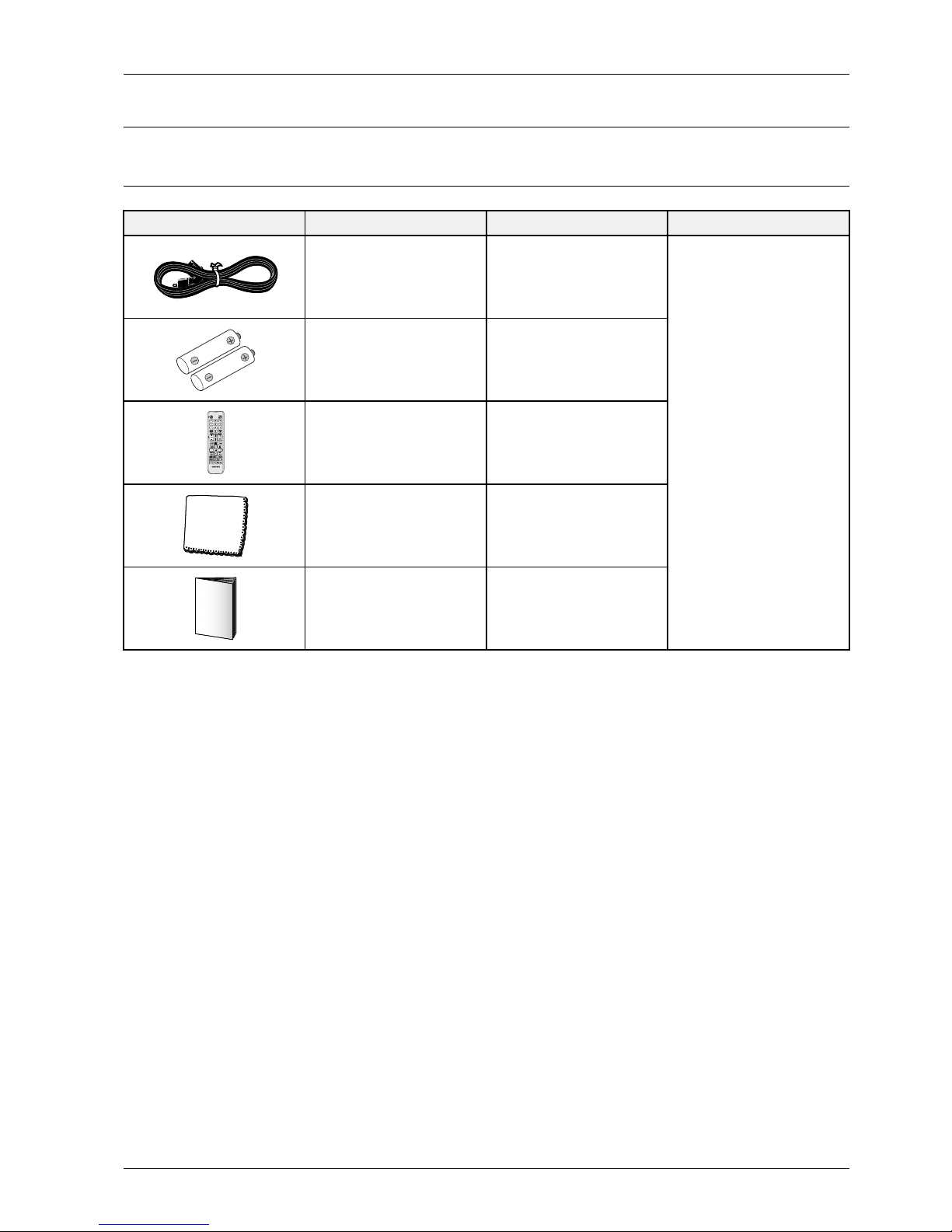
DescriptionDescriptionPhotoScrew
1.Placemonitorfacedownoncushionedtable.
Removescrewsfromthestand.
Removestand.
<Rearviewof43">
<Rearviewof43">
6003–001782
M4*L12
2.RemovethescrewsofRear-Cover.
<Rearviewof43">
6003–001782
M4*L12
6003–000337
M4*L10
Copyright©1995-2012SAMSUNG.Allrightsreserved.3-1

3.DisassemblyandReassembly
DescriptionDescriptionPhotoScrew
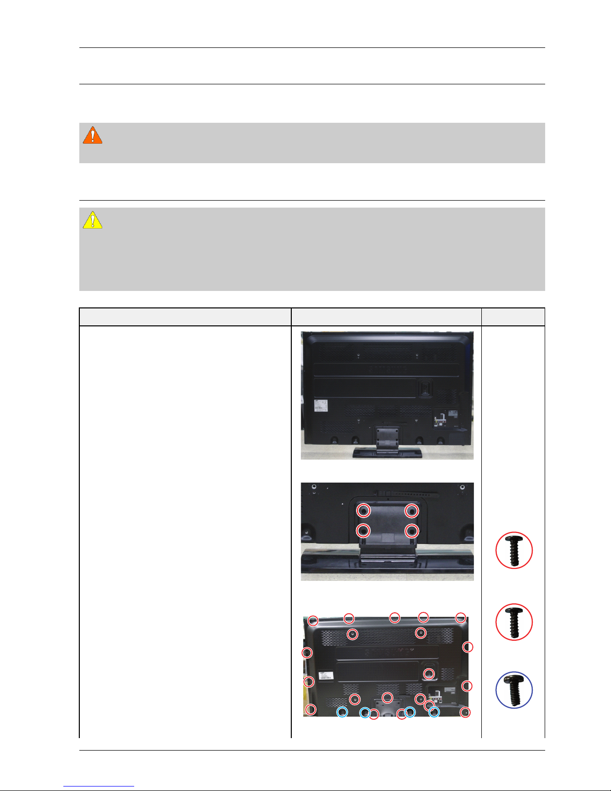
3.LiftupandremovetheRear-Cover.
<Rearviewof43">
4.RemovethescrewsofMainBoard.
CAUTION
Disconnectallconnectorspriortoremoving
boards.
6001–002606
M3*L10
RemovethescrewsofSMPS.RemovetheSMPS.
CAUTION
Alignboardundertabwhenre-installing.
6001–002606
M3*L10
6003–001439
M4*L8
5.Removethespeakers(R/L)
3-2Copyright©1995-2012SAMSUNG.Allrightsreserved.
3.DisassemblyandReassembly
DescriptionDescriptionPhotoScrew
RemovethescrewofCoverbottom.
<Rearviewof43">
6003–001782
M4*L12
6.Removethescrewsofthefront-cover.
<Rearviewof43">
6003–001782
M4*L12
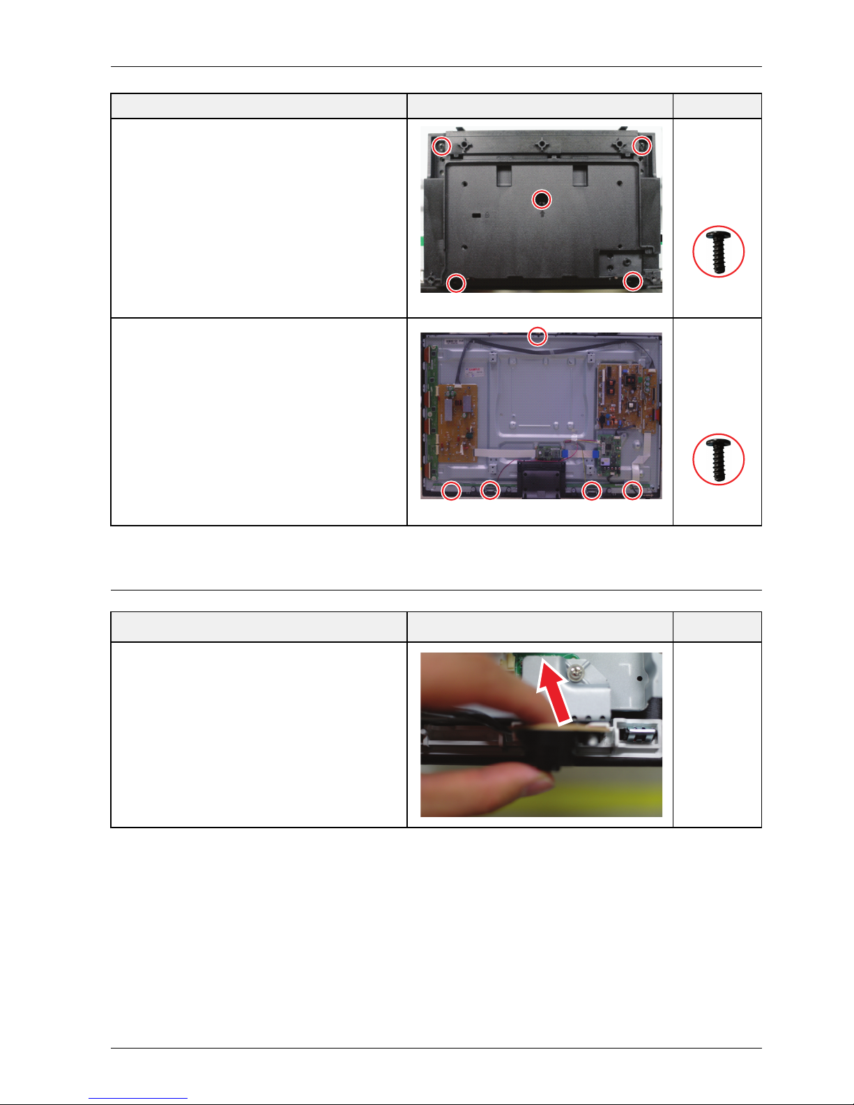
3.1.1.MethodforDisassemblyofFunctionAssy
DescriptionDescriptionPhotoScrew
1.PinchtheFunctionPCBbetweenyourngersand
gentleypullawayfromfrontcoverclip.
Copyright©1995-2012SAMSUNG.Allrightsreserved.3-3

4.Troubleshooting
4.Troubleshooting
4.1.Troubleshooting
4.1.1.FirstChecklistforTroubleshooting
1)Checkthevariouscableconnectionsrst.
•Checktoseeifthereisaburntordamagedcable.
•Checktoseeifthereisadisconnectedorloosecableconnection.
•Checktoseeifthecablesareconnectedaccordingtotheconnectiondiagram.
2)CheckthepowerinputtotheMainBoard.
3)HowtodistinguishiftheproblemiscausedbyMainboardorLogicBoard.
•NoVideo:IftheproblemisNoVideobutLogicBoardisonandIndicationLEDisblinkingrepeatedlyand
fasterthannormalbooting,replacetheLogicboard.
•DistortedPicture:Checktheinnerpatterns.
InnerpatternPictureProblem
OKNGMainBoard
NGNGMainorL VDScableorLogicBoardorPanel.
•Howtocheckinnerpattern?
a.Factorymode
b.MovetoSVCmenu.
c.MovetoT estPattern.
d.Checkinnerpatterns.(ThismodelonlysupportFBE,READPRE,READPOST)
4-1Copyright©1995-2012SAMSUNG.Allrightsreserved.

4.Troubleshooting
4.1.2.CheckpointsbyErrorMode
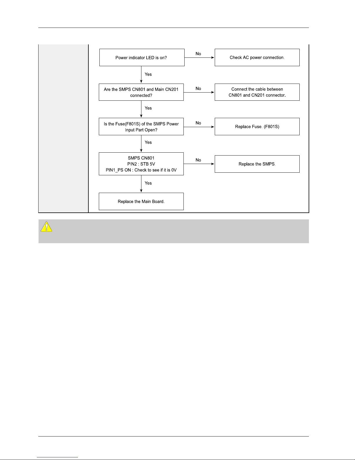
■NoPower
Symptom
•TheLEDsonthefrontpaneldonotworkwhenconnectingthepowercord.
•TheSMPSrelaydoesnotworkwhenconnectingthepowercord.
•Theunitappearstobedead.
MajorChecklist
TheSMPSrelayortheLEDsonthefrontpaneldoesnotworkwhenconnectingthepowercordif
thecablesareimproperlyconnectedortheMainBoardorSMPSisnotfunctioning.Inthiscase,
checkthefollowing:
•Checktheinternalcableconnectionstatusinsidetheunit.
•Checkthefusesofeachpart.
•ChecktheoutputvoltagesoftheSMPS.
•ReplacetheMainBoard.
Diagnostics
CN801
CN201
Fuse
<Rearviewof43">
Copyright©1995-2012SAMSUNG.Allrightsreserved.4-2
4.Troubleshooting
Ye s
Ye s
Ye s
Ye s
P owe r ind ica to r LED is o n?
Che ck AC powe r con ne ction.
Re place the Ma in Bo a rd.
Conn e ct the cable b e twe e n
CN801 a nd C N20 1 co nne ctor.
Are th e SMPS CN80 1 a nd Ma in C N20 1
conn e cte d?
Re place Fus e. (F8 01S )
Is th e Fus e (F8 01S ) of the S MPS P o we r
Input P a rt Ope n?
Re place the S MPS.
SMPS CN80 1
PIN2 : S TB 5V
PIN1_P S O N : Che ck to se e if it is 0V
No
No
No
No
CAUTION
MakesuretodisconnectthepowerbeforeworkingontheSMPSboard.
4-3Copyright©1995-2012SAMSUNG.Allrightsreserved.
4.Troubleshooting
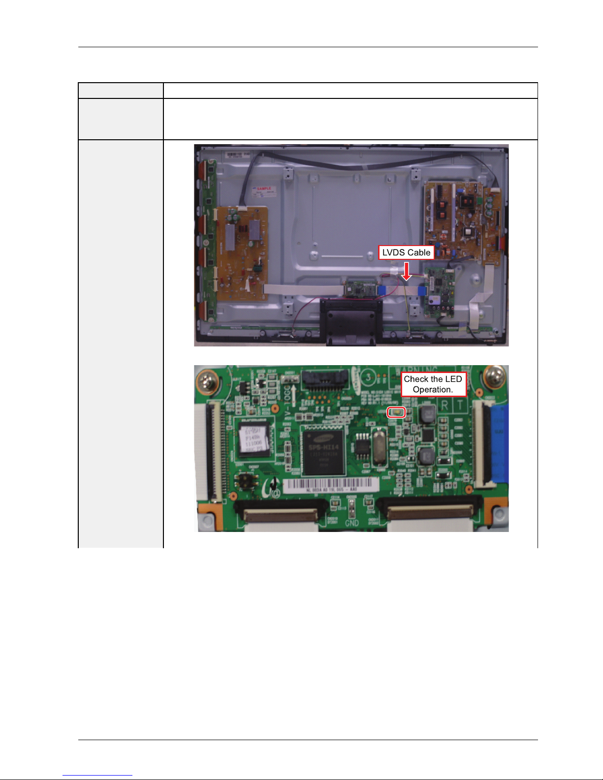
■NoVideo
Symptom•Audioisnormalbutnopictureisdisplayedonthescreen.
MajorChecklist
•TheoutputvoltageoftheMainSMPS.
•ThismayhappenwhentheLVDScableconnectingtheMainBoardandthePanelis
disconnected.
Diagnostics
LVDS Cable
<Rearviewof43">
Check the LED
Operation.
<Rearviewof43">
Copyright©1995-2012SAMSUNG.Allrightsreserved.4-4

4.Troubleshooting
Ye s
Ye s
Ye s
Re place the Main Boa rd.
Che ck / Re pla ce the LVDS C a ble.
Che ck the LVDS conn e ctor.
Is it con necte d co rre ctly?
Re place the S MPS .
Che ck All output voltag e s o n S MPS.
Are a ll voltag e n e rma l?
Re place the Logic Boa rd.
Che ck the LED ope ra tion of Logic Boa rd
whitch is norma lly ope rating?
(Norma l : Blink on ce a s e con d)
No
No
No
CAUTION
MakesuretodisconnectthepowerbeforeworkingontheSMPSboard.
4-5Copyright©1995-2012SAMSUNG.Allrightsreserved.

4.Troubleshooting
■NoSound
Symptom•Videoisnormalbutthereisnosound.
MajorChecklist
•Whenthespeakerconnectorsaredisconnectedordamaged.
•WhenthesoundprocessingpartoftheMainBoardisnotfunctioning.
•Speakerdefect.
•SMPSnotsupplyingvoltagetothemainboard.
Diagnostics
Speaker
Speaker Cable
CN801
<Rearviewof43">
Ye s
Ye s
Ye s
Re place the S pe a ke r.
Re place the S MPS .
Is th e outpu t voltag e o f S MPS norm a l?
(CN801 P IN 7 : 15 V)
Re place the Ma in b oa rd.
(1)
Is th e spe ake r o utpu t te rm ina l of
the Main boa rd norm a l?
Conn e ct the cable p rop e rly or
repla ce the cable , if ne cess a ry.
Is th e ca b le co nn e c tion be twee n
Main b oa rd a nd th e s pea ke r
prope rly co nn e cte d?
No
No
No
So und O utpu t Sh ape
(1)
Copyright©1995-2012SAMSUNG.Allrightsreserved.4-6
 Loading...