


_............_Owner's
Instructions

l Warninq ! Important
Safety Instructions
CAUTION
CAUTION: TO REDUCE THE RISK OF ELECTRIC SHOCK, DO NOT
REMOVE COVER (OR BACK). NO USER SERVICEABLE PARTS INSIDE.
REFER SERVICING TO QUALIFIED SERVICE PERSONNEL.
This symbol indicates high voltage is present inside, It is
dangerous to make any kind of contact with any inside part of
this product.
This symbol alerts you that important literature concerning
operation and maintenance has been included with this producL
Note to CATV system installer: This reminder is provided to call CATV system
installer's attention to Article 820 40 of the National Electrical Code (Section 54 of
Canadian Electrical Code, Part I), that provides guidelines for proper grounding
and, in particular, specifies that the cable ground shall be connected to the
grounding system of the building as close to the point of cable entry as practical.
Caution: FCC/CSA regulations state that any unauthorized ehanges or modillca
tlons to this equipment may void the user's authority to operate it.
Caution: To prevent etectric shoek, match the wide Made of plug to the wide slot,
and fully insert the plug.
Attention: pour eviter les chocs electriques, introduire la lame le ptus large de la
fiche dans la borne correspondante de la prise et pousserjusqu'au fond.
Important: One Federal Court has held that unauthorized recording of
copyrighted TV programs is an infringement of U.S. copyright laws.
Certain Canadian programs may also be copyrighted and any unauthorized
recording in whole or in part may be in violation of these rights.
To prevent damage which may result in fire or electric shock
hazard, do not expose this appliance to rain or moisture.

Thank You for Choosing Samsung
Thank you for choosing Samsung! Your new Samsung Projection TV represents the latest hi
television technolog]t We designed it with easy to use on screen menus and dosed captioning
capabilities, making it one of the best products in its class. We are proud to offer you a product
that will provide convenient, dependable service and enjoyment for years to come.
Important Safety Information
Always be careful when using your TV receiver. To reduce the risk of fire, electrical shock,
and other injuries, keep these safety precautions in mind when installing, using, and
maintaining your machine.
• Read all safety and operating instructions before operating your T_
• Keep the safety and operating instructions for future re%fence.
• Heed all warnings on the TV receiver and in the operating instructions.
• Follow all operating and use instructions.
• Unplug the TV receiver from the wall outlet befure cleaning. Use a damp cloth; do not use
liquid or aerosol cleaners.
• Never add any attachments and/or equipment without approval of the manufacturer. Such
additions can inci-ease the risk of fire, electric shock, or other personal injury.
• Do not use the TV receiver where contact with or immersion in water is a possibility, such as
near bath tubs, sinks, washing machines, swimming pools, etc.
• Do not place the TV on an unstable cart, stand, tripod, bracket, or
table where it can fail. A falling TV can cause serious injury to a
child or adult, and serious damage to the appliance. Use only with
a cart, stand, tripod, bracket, or table recommended by the manu
facturer or sold with the TV[ Pollow the manufacturer_ instruc
tions when mounting the unit, and use a mounting accessory rec
ommended by the manufacturer. Move the TV and cart with care.
Quick stops, excessive force, and uneven surfaces can make the
unit and cart unsteady and likely to overturn.
• Provide ventilation fur the TV receiver. The unit is designed with slots in the cabinet for
ventilation to protect it from overheating. Do not block these openings with any object, and
do not place the TV receiver on a bed, sofa, rug, or other similar surface. Do not place it near
a radiator or heat register. If you place the TV receiver on a rack or bookcase, ensure that
there is adequate ventilation and that you've followed the manufacturer_ instructions for
mounting.
• Operate your TV receiver only from the type of power source indicated on the marking label.
If you are not sure of the type of power supplied to your home, consult your appliance dealer
or local power compan]t
• Use only a grounded or polarized outlet. For your safety, this TV is equipped with a polarized
alternating current line plug having one blade wider than the other. This plug will fit into the
power outlet only one walt If you are unable to insert the plug fully into the outlet, try
reversing the plug. If the plug still does not fit, contact your electrician to replace your outlet.
SAFELY
• Protect the power cord. Power supply cords should be routed so that they won't be walked on
or pinched by objects placed on or against them. Pay particular attention to cords at plugs, con
venience receptacles, and the point where they exit from the unit.
• Unplug the TV from the wall outlet and disconnect the antenna or cable system during a light
ning storm or when left unattended and unused for long periods of time. This will prevent dam
age to the unit due to lightning and power line surges.
• Avoid overhead power lines. An outside antenna system should not be placed in the vich]ity of
overhead power lines or other electric light or power circuits or where it can fail into such
power lines or circuits. When installing an outside antenna system, be extremely careful to keep
from touching the power lines or circuits. Contact with such lines can be fatal.
• Do not overload the wall outlet or extension cords. Overloading can result in fire or electric
shock.
• Do not insert anything through the openings in the unit, where they can touch dangerous volt
age points or damage parts. Never spill liquid of any kind on the TV
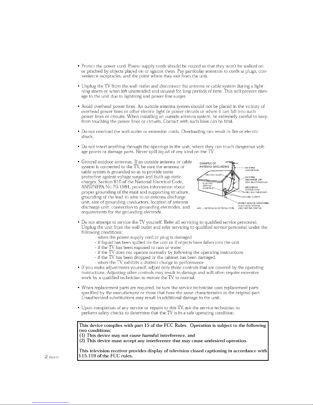
• Ground outdoor antennas. If an outside antenna or cable
system is connected to the TV_ be sure the antenna or
cable system is grounded so as to provide some
protection against voltage surges and built up static
charges. Section 810 of the National Electrical Code,
ANSI/NFPA No.70 1984, provides infurmation about
proper grounding of the mast and supporting structure,
grounding of the lead in wire to an antenna discharge
unit, size of grounding conductors, location of antenna
discharge unit, connection to grounding electrodes, and
requirements for the grounding electrode.
EXAMPLEQF
ANTENNAGROUNDING
• Do not attempt to service the TV yourself. Refer all servicing to qualified service personnei.
Unplug the unit from the wall outIet and refer servicing to qualified service personnel under the
fullowing conditions:
when the power supply cord or plug is damaged
if liquid has been spilIed on the unit or if objects have fallen into the unit
if the TV has been exposed to rain or water
if the TV does not operate normally by following the operating instructions
if the TV has been dropped or the cabinet has been damaged
when the TV exhibits a distinct change in performance
• If you make adjustments yourself, adjust only those controls that are covered by the operating
instructions. Adjusting other controls may result in damage and will often require extensive
work by a qualified technician to restore the TV to normal.
• When replacement parts are required, be sure the service technician uses replacement parts
specified by the manufacturer or those that have the same characteristics as the original part.
Unauthorized substitutions may result in additional damage to the unit.
• Upon completion of any service or repairs to this TV] ask the service technician to
perform safety checks to determine that the TV is in a safe operating condition.
This device complies with part 15 of the FCC Rules. Operation is subject to the following
two conditions:
(1) This device may not cause harmful interference, and
(2) This device must accept any interference that may cause undesired operation.
This television receiver provides display of television closed captioning in accordance with
2 s_._ 15.119 of the FCC rules.

Important Warranty Information
Regarding Television Format
Viewing
Standard screen format televisions (4:3, the aspect ratio of the screen width to height) are
primarily designed to view standard format l'ull motion video. The images displayed on
them should pi-imari[y be in the standard 4:3 ratio format and constantly moving.
Displaying stationary graphics and images on screen, such as the dark top and bottom
letterbox bars (wide screen pictures), should be limited to no more than 15% of the total
television viewing per week.
Wide screen format televisions (l 6:9, the aspect i-atio of the screen width to height) are
primarily designed to view wide screen format fuli motion video. The images displayed
on them should primarily be in the wide screen 1 6:9 ratio format, or expanded to fill the
screen if your model offers this feature, and constantly moving. Displaying stationary
graphics and images on screen, such as the dark side bars on non expanded standard
format television video and programming, should be limited to no more than 15% of the
total television viewing per week.
Additionally, viewing other stationary images and text such as stock market reports,
video game displays, station logos, web sites or computer graphics and patterns, should
be limited as described abo\ e for all televisions. Displaying ar_y stationarly images that
exceed tile above guidelines can cause uneven aging of picture tubes (CRTs) that leave subtle,
but permanent burned in ghost inlages in the television picture. To avoid this, vary the program-
ruing and images, and prinla_41y display full screen moving inlages, not stationaly patterns or
da_k bars. On television models that offer picture sizing features, use these controls to
view the different ft_rmats as a full screen picture.
Be careful in the selection and duration of television formats used for vie_ving. Uneven
CRT aging as a result of' format selection and use, as well as other burned in images, is
not covered by your Samsung limited warranty.

CONTENTS ]
Chapter 1: Your New TV ............... 1.1
List of Features .......................................... 1.1
Familiarizing Ycourselfwith YcourNew TV ...................... 1.2
Front Panel Buttons ............................... 1.2
Front/Side Panel lacks ............................. 1.3
Using the Component Shelf ......................... 1.t'_
Rear Panel lacks .................................. 1.4
Remote Control .................................. 1.5
Chapter 2: Installation ................ 2.1
Connecting VHF and UHF Antermas ......................... 2.1
Antennas with 300 ohm Flat _bvin Leads ............... 2.1
Antennas with 75 ohm Round Leads .................. 2.2
Separate VHF and UHF Antennas .................... 2.2
Connecting Cable TV ..................................... 2.2
Cable without a Cable Box .......................... 2.2
Connecting to a CabJe Box that Descrambles
All Channels .................................... 2.3
Connecting to a Cable Box that Descrambles
some Channels .................................. 2.{'_
Connecting a VCR ....................................... 2.5
Connecting a Second VCR to Record from the TV ........ 2.(5
Connecting a Camcorder .................................. 2.6
Connecting a DVD Player, DTV Set Top Box (480i, 480p, 1080i) . 2.7
Connecting a DTV Set Top Box (480p, 1080i) .................. 2.8
Installing Batteries in the Remote Corltrol ..................... 2.g
Chapter 3: Operation .................. 3.1
_lhrning the TV Or_and Off ................................ 3.1
Phtg & Play Featnre ...................................... 3.1
Using the Perfect Focus Feature ............................. 3.3
Ac]justing Manual convergerlce ............................. 3.4
Adjust Red Convergence ........................... 3.5
Viewing the Menus and On Screen Displays ................... 3.6
Viewing the Menus ............................... 3.6
Viewing the Display ............................... 3.6
Selecting a Menn Langnage ................................ 3.7
Selecting the Antenna Input ................................ 3.7
Memorizing the Channels ................................. 3.8
Selecting the Video SignaJ source ..................... 3.8
Storing Channels it1Memory (Antomatic Method) ........ 3.9
Adding and Erasing Charlnels (Manual Method) ......... 3.9
Changing Channels ..................................... 3 10
Using the Channel Buttons ........................ 3 10
Using the Number Buttons ........................ 3 10
Using the Previons Channel ........................ 3 10
Selecting Your Favorite Channels ........................... 3 11
_I_ Store Your Favorite Channels: .................... 3 11
_I_ View Your Favorite ChanneJs: .................... 3 11
Addirlg and Erasing Channels (Manual Method) ............... 3 12
Labeling the Channels ................................... 3 13
Picture Control ........................................ 3 14
Customizing the Picture ........................... 3 14
Using Automatic Picture Settings .................... 3 15
Selecting the Color Tcone .......................... 3 16
Chapter 3: Operation (Cont.) .......... 3.16
(_ON/EN/S

CONTENTS
Sound Control ......................................... 3.16
Adjusting the Volulne ............................ 3.16
Using Mute .................................... 3.16
Customizing the Sound ........................... 3.17
Using Automatk Sound Settings .................... 3.18
Setting the Clock ....................................... 3.10
Option 1: Setting the Clock Manually ................ 3.19
Option 2: Using the Local PBS Channel to Automatically
Set the TV Clock ................................ .'3.20
Chapter 4: Special Features ............ 4.1
Fine 1lining Channels .................................... 4 1
Digital Noise Reduction ................................... 4 2
Changing the Screen Size .................................. 4 8
Using the R.surf Feature ................................... 44
Settingthe On/Off Timer .................................. 45
Settingthe SleepTimer ................................... 46
Extra sound settings ...................................... 47
Choosing a Multi Channel Sound (MTS) track ................. 48
Viewing Closed Captions .................................. 49
Viewing Picture in Picture ................................ 4. l0
Activating Pkture-in Picture ....................... 4. l0
Selecting a Signal Source (Antenna or Cable) for PIP ..... 4.11
Selecting a Signal Source (External A/V) for PIP ......... 4.1 i
Swapping the Contents of the PIP image and Main image 4.12
Changing the Size of the PIP Window ................ 4.12
Changing the PIP Channel ......................... 4.13
Changing the Location (Rotating) the PiP mode ........ 4.13
Scanning the Available Channels .................... 4.13
Using the VChip ....................................... 4.14
Setting Up Your Personal ID Number (PIN) ............ 4.14
How to Enable/Disable the _Chip ................... 4.15
How to Set up Restrictions Using the "TV guidelines" . . 4.15
How to Set up Restrictions using the MPAA Ratings:
G. PC, PC i3, R, NC 17, X ........................ 4.17
How to Reset the TV after the VChip Blocks
a Channel ("Emergency Escape") .................... 4.18
Viewing the Demonstration ........................ 4.19
Customizing Your Remote Control .......................... 4.20
Setting Up Your Remote Control to Operate Your
VCR or DVD ................................... 4.20
Setting Up Your Remote Control to Operate Your
Cable Box ..................................... 4.21
Chapter 5: Troubleshooting ............ 5.1
Icientifying Problems ..................................... 5 1
Appendix ........................... A.1
Cleaning and Maintaining Your TV .......................... A i
Using Your TV in Another Country .......................... A 1
Specifications ........................................... A 1
( _H_H_s2
Your NEW TV
List of Features
Your Samsung TV vvas designed with the latest tecbnolog_v This TV is a high perfurmance
unit that includes the following special features:
Easy to use remote control
Easy to use on screen menu system
Automatic timer to turn the TV on and off
Adjustable picture and sound settings that can be stored in the TV_ memory
Automatic channel tuning fur up to 181 channels
A special filter to reduce or eliminate reception problems
Fine tuning control for the sharpest picture possible
A built in multi channel sound decoder for stereo and bilingual listening
Built in, dual channel speakers
A special sleep timer
Picture in Picture
Component Video Input jacks to obtain a sharper image from external sources
Peribct Focus
_._ (2}lAP I ON} Y( t}l N]\% V

I Your NEw TV
Familiarizing Yourself with The TV
Front Panel Buttons
The buttons on the front panel control your TV_ basic features, including the on screen
menu. Tu use the more advanced features, you must use the remote control.
HCM4215W / HCM4216W / HCM422W
000 • • 000
HCM5525WB / HCM653WB / HCM553WB / HCM474W
000 @ • • OO
PCM541551
OO 0000 • 0
HCM4715W HCM556W
00000 O0 •
O TV/VIDEO
All the inputs connected to the external
componentjacks will be shown in regular
sequence.
O MUTE
Press to temporarily cut off the sound.
O MENU
Pressto seeanon screen menuofyour TV'sfeatures,
O VOL-, +
Press to increase or decrease the volume,Also
used to select items on the on screen menu.
CH_" and OH&
Press to change channels, Also press to highlight
various items on the on screen menu.
Remote Control Sensor
Aim the remote control towards this spot onthe TV.
Timer indicator
WhentheTVisturnedon,the limer indicatorblinks
abouttentimes,Thisindicatorilluminateswhenthe
1]mermodeis settothe" On"positionaftersettingthe
clockandeithertheOntimeror Offtimer,with the
remotecontrol.Evenifthepower isturnedof[, this
indicatorstayslit. (Clockmustbe setbefore usingthis
function,),
O POWER
Pressto turn the TVon and off,
Your NEw TV ]
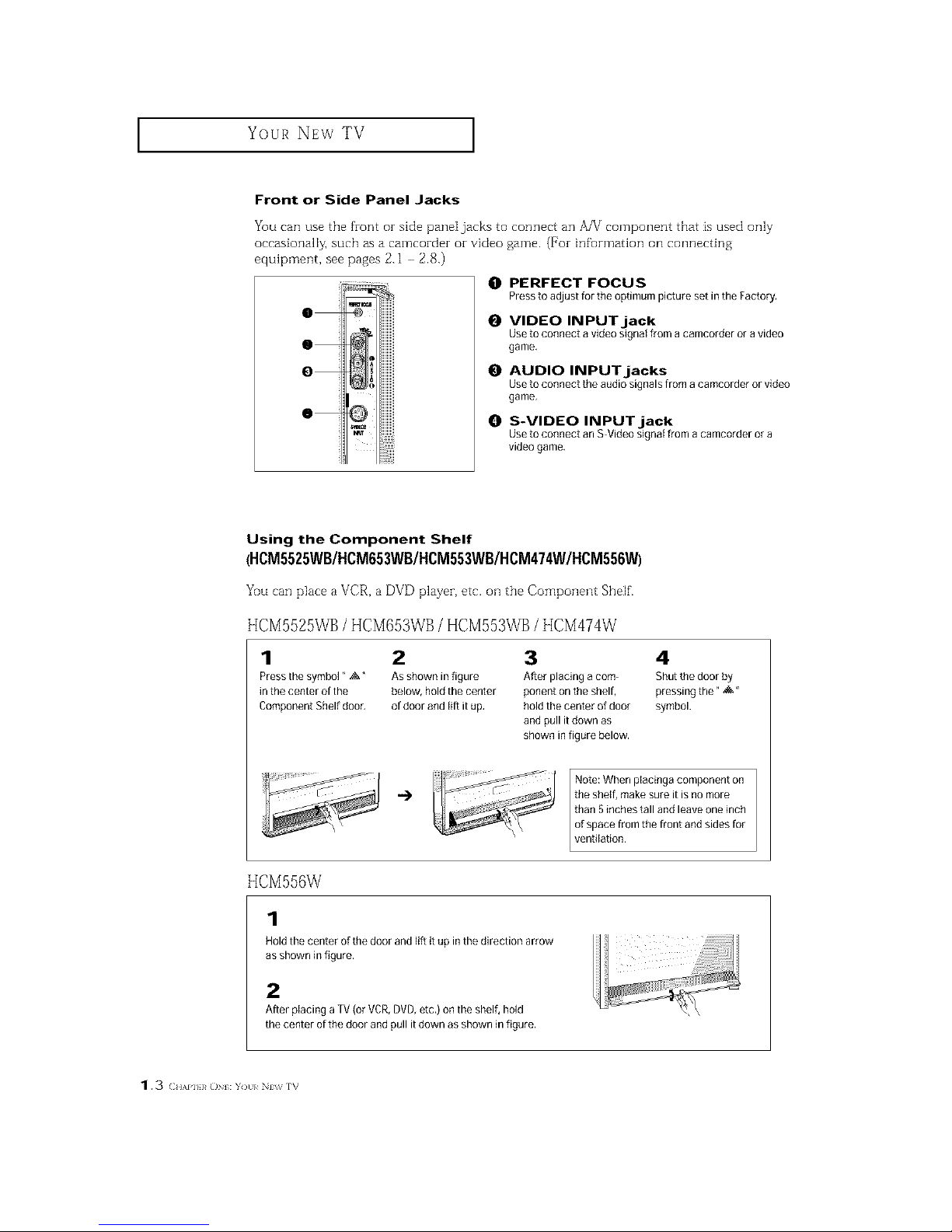
Front or Side Panel Jacks
You can use the front or side pane[jacks to connect an A/V component that is used only
occasionally, such as a camcorder or video game. (For infurmation ollconnecting
equipment, see pages 2.1 2.8.)
0
O
O
O
O PERFECT FOCUS
Presstoadjustfortheoptimumpicturesetin theFactory,
O VIDEO INPUT jack
Use to connect a video signal from acamcorder or a video
game,
O AUDIO INPUTjacks
Use to connect the audio signals from acamcorder or video
game.
O S-VIDEO INPUTjack
Use to connect an S Video signal from acamcorder or a
video game,
Using the Component Shelf
(HCM5525WB/HCM653WB/HCM553WB/HCM474W/HCM556W)
Yuu can place a VCR, a DVD player, etc. ollthe Component Shelf.
HCM5525WB/HCM653WB/HCM553WB/HCM474W
1 2
Press the symbol" ,:&" Asshown in figure
in the center of the below, hold the center
Component Shelf dooc of door and lift itup,
3 4
After placing a corn- Shut the door by
ponent on the shelf, pressing the* _&"
hold the center of door symbol.
and pull it down as
shown in figure below.
HCM556W
1
Note: When placinga component on
"_ ttIi_sh5elnf,chme_kteai_t-are_tlieSa__ omn_riech
of space from the front and sides for
Lvenfilation.
Hold the center of the door and lift it up inthe direction arrow
as shown in figure,
2
After placing a TV (or VCR,DVD,etc,) on the shelf, hold
the center ofthe door and pull it down as shown in figure.
1.3 ( HAPI}}_O : Y)tl/ Nv_ rv

Your NEw TV ]
Rear Panel Jacks
Use the zear parle] jacks to connect an A/V component that will be connected conthlu
ously, such as a VCR or a DVD player.
Because theze are two sets of inputjacks, you can connect two different A/V components
(i.e., a VCR and a DVD, 2 VCRs, etc.)
For more inf_rmation oil connecting equipment, see pages 2.1 2.8.
0 @0 • • • 0
0 ANTENNA terminals
Two independent cables or antennas can be
connected to these terminals, UseANT-A and
ANTB terminals to receive a signal from
VHHUHFantennas or your cable system. Use
the ANTA OUTterminal to send the signal being
received by the ANnA terminal out to another
component (such as a CableSet TopBox),The
PiP channel can be received only when a signal
source is connected to ANT A.
O
AUDIO-VIDEO MONITOR
OUTPUT jacks
Connect to the audio/video inputjacks of a
recording VCR,
Note: The monitor out does not operate in DVD
or DTV mode.
O
VIDEO INPUT jacks
Connect to the video output jacks of VCRs,DVD
players and similar devices (Two sets are avail
abie: Video1 and Video2),
0 AUDIO INPUT jacks
Connect to the audio output jacks of VCRs,DVD
players and similar devices.
O S-VIDEO INPUT jack
Connectto anSVHSVCRor DVDplayer.
0 COMPONENT 1(480i, 480p,
1080i) AUDIO/VIDEO INPUT
jacks
Connecta sourcethatoutputs480i/480p/1080i
Y,PL_andP,signals,suchasaDVD(orDTVSet-
TopBox.
0 COMPONENT 2, 3(480p,
1080i) AUDIO/VIDEO INPUT
jacks
Connect a source that outputs 480p/1080iY,P,_
and P,_signals, such asa DTVSet-Top Box,
(The Component3 jack is available on PCM545PJ
HCM422W/ HCM474W/ HCM553WB /
HCM653WB)
Your NEw TV ]
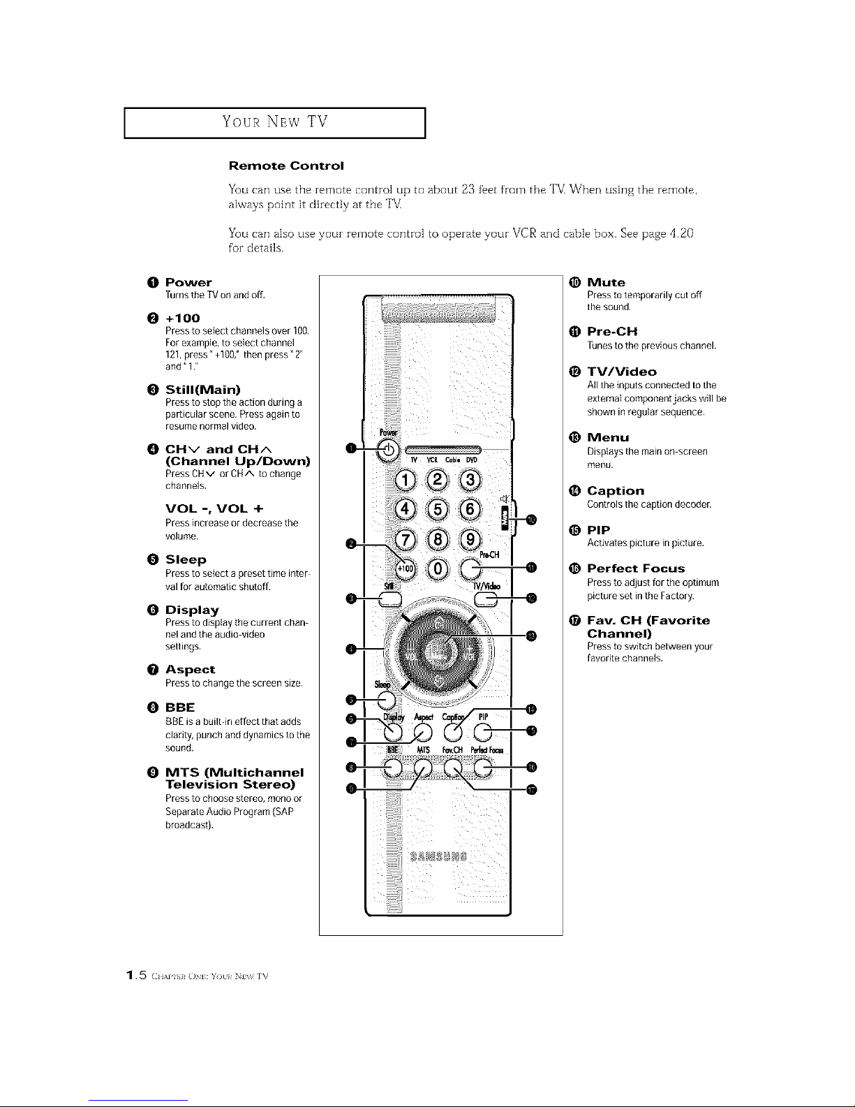
Remote Control
You can use the remote control up to about 23 fi_et from the ']'V_When ush]g the remote,
always point it directly at the TV
You can also use your remote control to operate your VCR and cable box. See page 4.20
for details.
10t Power
Turns the TVon and off,
O +100
Pressto select channels over 100.
For example, to select channel
121,press" +100," then press" 2"
and" 12
O Still(Main)
Pressto stop the action during a
particular scene, Press again to
resume normalvideo.
CHv and CHA
(Channel Up/Down)
Press CHv or CHA to change
channels.
VOL -, VOL +
Press increase or decrease the
volume.
0 Sleep
Pressto select a preset time inter
val for automatic shutoff.
0 Display
Pressto display the current chan
nel and the audio video
settings,
O Aspect
Pressto changethescreensize.
O BBE
13BEis a built-in effect that adds
clarity, punch anddynamics to the
sound,
0 MTS (Multichannel
Television Stereo)
Pressto choose stereo, mono or
Separate Audio Program (SAP
broadcast).
iiiiiiiiiiii!!i
@ Mute
Pressto temporarily cut off
the sound.
Pre-CH
Tunesto the previous channel.
_) IV/Video
All the inputs connected to the
external componentjacks will be
shown inregular sequence.
@ Menu
Displays the main on screen
menu,
Caption
Controls the caption decoder.
PIP
Activates picture in picture,
_) Perfect Focus
Pressto adjust fortile optimum
picture set inthe Factory.
Fav. CH (Favorite
Channel)
Pressto switchbetweenyour
favoritechannels.
1.5 (;.,,,p. _o :Y)tl/ N_ rv
I Your NEw TV
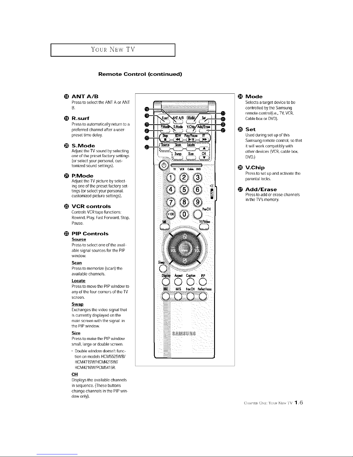
Remote Control (continued)
ANT A/B
Press to select the ANT A orANT
B.
R.surf
Press to automatically return to a
preferred charnel after a user
preset time delay.
S.Mode
Adjust the TVsound by selecting
oneof the preset factory settings
(or selectyour personal, cus
tomized sound settings),
P.Mode
Adjust the TVpicture by select
ing one of the preset factory set
tings (or select your personal,
customized picture settings),
VCR controls
Controls VCRtape functions:
Rewind, Play, FastForward, Stop,
Pause.
PiP Controls
Source
Press to select one of the avail
able signal sources for the PIP
window,
Scan
Press to memorize (scan) the
available channels,
Locate
Press to movethe PIPwindow to
any of the four corners of the TV
screen,
Exchangesthe video signal that
is currently displayed on the
main screen with the signal in
the PIP window,
Size
Press to makethe PIPwindow
small, largeor double screen,
• Double window doesn't func
tion on models HCM5525WB/
HCM4715W/HCM4215W/
HCM4216W/PCM5415R,
614
Displays the available channels
in sequence, (Thesebuttons
change channels in the PIP win
dow only).
@
@
Mode
Selects atarget device to be
controlled by the Samsung
remote controi(Le,, TV,VCR,
Cable box or DVD),
Set
Used during set up of this
Samsung remote control, sothat
it wiflwork compatibly with
other devices (VCR,cable box,
DVD.)
V.Chip
Press to set up and activate the
parental locks.
Add/Erase
Press to add or erase channels
in the TV's memory,
C]I_P ii ON}: Yot}}_ NI;_ IV 1.6

INSTALLATION
Connecting VHF and UHF Antennas
If youz antenna has a set of leads that
look like this, see "Antennas with
300 ohm Flat _vin Leads," below.
If youz antenna has one lead that looks
like this, see "Antennas with 75 ohm
Round Leads," oil page 2.2.
If you have two antennas, see "Sepai-ate
VHF and UHF Antennas," oil page 2.2.
Antennas with 300-ohm Flat Twin Leads
If'you aze using an off air antenna (such as a zoof antenna or "zabMt eazs") that has 300
ohm twin fiat leads, follow the dizections below.
Place the wires from [h_
twin leads under the
screws onthe 300_75
ohm adaptor (not sup-
plied). Use a screwdriver
_etighten the screws.
i
2
Plugme aoaptorintothe
ANT-AorANr-Bterminal
_ntherearpanel.

INSTALLATION ]
Antennas with 75-ohm Round Leads
Plugthe antenna lead
into the AN%A or ANT-B
terminal o
Separate VHF and UHF Antennas
If you have two separate antennas foz your TV (one VHF and one UHF), you must combine
the two antenna signals befoze connecting the antennas to the T_ This pzoceduze requh-es a
an optional combinez adaptor (available at most electronics shops).
Connect bothantenna
earls to the combiner.
2
3lugthecombinerinto
Connecting Cable TV
You can connect different cable systems to youz TV, inciuding cable without a cable box,
and cable with a cable box that descrambles some oz all channels.
Cable without a Cable Box
If you want to connect eabIe, and you do not need to use a cable box:
Plugthe incoming cable
into the ANT-A orANT-B
antenna terminoi on the
rear of the TV.
(} I,\P] l _( / ]NSIAI AI( /N _ * 2

INSTALLATION ]
Cable with a Cable box that Descrambles All Channels
terminal might be
Iabeled" ANT OUT'r
Connect the other end of ]
this cable to th_
or ANT_Bterminal onthe
rear of the TV,
Connecting to a Cable Box that Descrambles Some Channels
If your cable box descrambles orgy some channels (such as premium channels), fallow the
instructions below. You will need a two way splitter, an RE (A/B) switch, and fuur lengths of'
coaxial cable. (These items are available at most electronics stores.)
,-indanddisconnectthe
cablemat_sconnectee
totheANTENNAINter- _(] IN NA
mmal on your c_bJe box,
This terminal might be labeled
"ANT IN," "VI [F IN," or simply,
"IN."
2
Connect this cabJem a
[wo-way SplIEeL
neemleg
8plKler
3
CoRnet[ a coaxial cable
3etween an OUTPUT [er
"Rli]al oR Ltle S_ Lter ai1c
[ne {N terminaI otl the
cable box.
riP.orrllrlg
CableBox
2.3 (HAP] I IV(} ]NSI\I],\I_N

INSTALLATION ]
4 /
Connect a coaxial cable nr_[_]
betweentheANTENNA _-_ ]_
. Incoming
OUTterminal on the Cable1
cable box and the B: !N Splitter
terminal onthe A/B
CableBox
RF(A/B)
8whch
Connect another cable _
between the other OUT
terminaJ on the splitter Irrupting
and the A- INterminal on ¢,a_e
the RF(A/B) switch, 8plffler RF(A/B)
CableBox Swnch
Connect i
cable between the OUT Incoming
terminai onthe RF(A/B) Cable
switch and the VHFIUHF
terminal onthe rear o[
the TV.
Splitter RF (A/B)
CableBox Switch
After you've made this connection, set the A/B switch to the "A" position for normal view
ing. Set the A/B switch to tile "B" position to view scrambled channels. (When you set the
A/B switch to "B," you will need to tune your TV to the cable box_ output channel, which is
usually channel 3 or 4.)
(} I,\P] 1%_11 ]NSIAI AII(/N 2.4

INSTALLATION ]
Connecting a VCR
These instructions assume that you have already connected your TV to an antenna or a
cable TV system (according to the instructions oil pages 2.1 2.3). Skip step 1 if you have
not yet connected to an antenna or a cable system.
Connect a coaxial cable between the
ANTENNA OUTterminal on the VCRand the
antenna [ermmal on me [V,
A coaxial cable is usuall z ixlduded wilh
VCR Ifnot che__ otlrJocmelect_mic_
_[oi'e
TV RearPanel
2
Connect a set of audio cabIes between the
AUDIO OUT acks on the VCRand the
AUDIO ,acks onthe
[l y _t_have a mono VCR. connect _ mol_o
{JVCR midio out usitlg oiny o[le at_cllo
-able
3
ConnectavideocablebetweentheVIDEO
OU] ackonthe VCRandthe VIDEO)ae_on
theTV.
[1yoIl have a S-VIIS VCR use the S-Video
"OrlKIOCklOXIS aglCl II_lnove IFIP video cable.
Do no_ com_ect the video c_ble and the S
Video cable to Video 1 slmmtaneoI_sly.
FoJlow the instIucUons in "Viewirlg a VCR
orCamcozdeiTape tovle yourVCRlape
VCRRearPanel
Note: This figure shows tile Standard Connactol_jack panel. The actual configuration on your TV may
bedifferent, depending on tile model.
2,5 (lI_}*] I IV() INS \llf ()N
I I
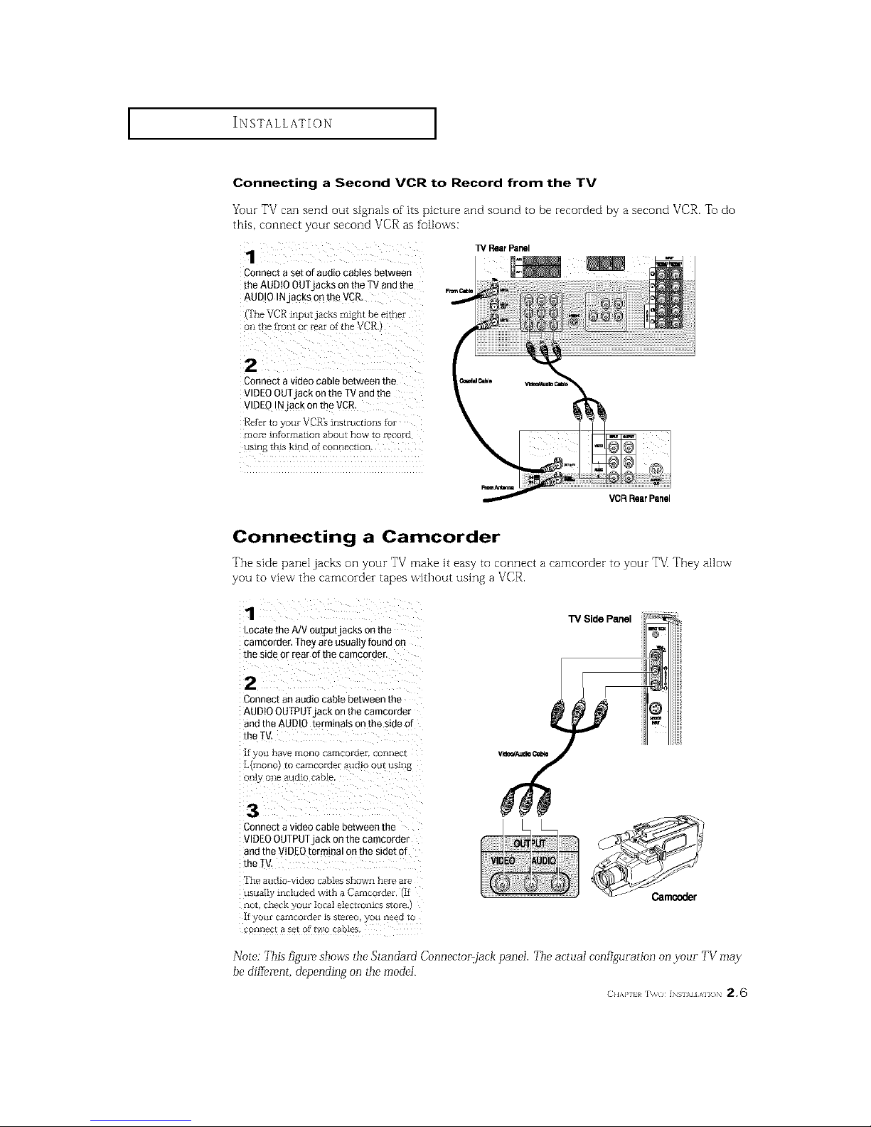
Connecting a Second VCR to Record from the TV
Your TV can send out signals of its picture and sound to be recorded by a second VCR. To do
this, connect your second VCR as follows:
13/RearPanel
Connect a set ofaudio canes between
[he AUDIOOUTjacks on the TV andthe
AUDIO INJacks Qnth_ VCP_
(TheVCR inputjacksmightbee!th_r
2
Connect a video cable between the
VIDEOOUTjack onthe TV end the
VIDEOINjack on the VCR.
Retbr to yore VCR's inslmctions for
more intbrmation about how to £ecord
VCRRearPanel
Connecting a Camcorder
'File side panel jacks orl your TV make it easy to connect a eamcorder to your TV They allow
you to view the cameorder tapes without using a VCR.
1
Locate the A/VoutputjacKs on me
camcomer. They are usua_q found on
me s_deor rear of the camcorde r
TV Side Panel
2
Connect an audio cable between the
AUDIO OUTPUI jack onthe camcorder
andthe AUDIO terminals on the side of
the rV.
[t yOtl have rnoHo gatl_gordpi COl-l]lpc[
L{moHo/ to camcor(lpi aucuo out using
on]3 one audio cable
3
3onnect a video cable between the
VIDEOOUTPUTack on the camcorde|
andthe VIDEOtermma_on me sme[ 3f
me TV.
]'he arid >-video callles shown heIe aIe
usual] included with a CaInroi_ter if
QO[ ght_ck g[)[_[ _[)[a_ P]P[I[OIlICS S[OrP
H yOtlY caII]COlQpF is S[PIPC oil neg_[_ [O
OflIleC_ a set O_ _WO cables
Note: This figme, shows tile Standard Connector,jack panel. The actual configuration on your TV may
be dif[emnt, depending on tile model.
(} I,\P] _ %_( / ] SIAl AI ( / 2,6

INSTALLATION ]
Connecting a DVD Player, DTV Set-Top Box
(480i, 480p, 1080i)
The rear panel jacks on your TV make it easy to connect a DVD player (or DTV Set Tup
Box) to yourTVI
Connecting to Y, P., P.
TVRearPanel
1
Connect a set of audio cables between
the DVD audio injacks on the TVand
the AUDIO OUTjacks on the DVDplayer
(or DTVSet:top Box.
2
Toenable Component videoviewing,
Connect video cables beLweenthe Y,Ps,
and P_inputs on the TV and Y,P_,and P_
(o_¥,C.,CJ_)outputs onthe DVDp_ayer
or DTVSet-Top Box.
Connecting to regular audio and video jacks
Connect a set of audio cables between
the AUDIO IN jacks on the TVand the
AUDIO OUT acks on the DVDplayer
lot DTV Set:[oo Box)
TVRearPanel
2
Connect video cables between the
VIDEOOUTjack on the DVDp_ayer
'or DTVSet-Too Box)and the V DEC
INjack on the TV.
DVDPleyer/D_/Set-T0pBox
DVDPlayer/DTVSet-TopBox
Note: This figure shows ttl_" Standald Connac'tol=jack pan_'I. The acmaI configuration on yo_ir TV may
be different, depending on tile model.
2.7 (IIA}*] I INSI\I]AI /)N

INSTALLATION ]
Connecting a DTV Set-Top Box (480p, 1080i)
When switching to the DTV mode, eitheI de0p oi 1080i foImat is automatically selected
according to the input signal.
Note: Only 480p and 1080i formats are supported.
Connect a set of auato cables between
the DTVSet-ToE}Box audio in acKs on
the TV andthe AUDtO OUT _ckson the
DTVSet-ToEpox
2
Toenable Component videoviewing.
2ortrtec[vtt3eo cables between the Y. P_
andP,dnoutsontheTVandY P_ andP
iorY. C,. C,I out[}uts onthe DTVSetZ[oD
30X
No[e_ FoF 24n Pxplar[euon oJ
Com[ _nent video see 3uI DTV Sel
_.019 ]dOXt; OWIleI'_ ln£tFI_CUOl
"iVRealPanel
DTV Set-T0p Box
(} I,\P] l _( / ]NSIAI AI ( )N 2,8

INSTALLATION ]
Installing Batteries in the Remote Control
Make sure to match the "+" and
"--" ends of the batteries with the
diagram inside the compartment.
Remove the batteries and store
them in a cool, dry place if you won't
be using the remote control for a
long time.
The remote control can be used up
to about 23 tbet from the TM
(Assuming typical TV usage, the
Batteries last for about one yeai_)

OPERATION
Turning the TV On and Off
Pressthe Power button,
You can also use the POWER button on the tbont panel.
Plug & Play Feature
When the TV is initiaI[y powered On, five basic customer settings proceed automatically and
subsequently: Setting the language, Ant. input check, and Auto program/Setting the Clock.
1
Press the Power button on
the remote control.
i
p_&P_y
The message" Ptug & Play"
is displayed,
It flickers for a little while and
then the _Language" menu is . ...........................................................................................................................................................
automatically displayed
Pressthe VOL + orVOL-
button to select the desired
language. Press the Menu
button to enter the language,
and then the YANT/CATV"
menu is autom@ticatty
displayed,
3
Pressthe VOL+ or VOL-
button to select the aes_reom
video stgnaI source.
Pressthe Menu button to
enter the video signal source
and then the "Ant Inau[
±_loet IE_t
check" is automauca.y
amp_ayec
continued...
(2HAl,l} 1¢ IEl}¢i IV ()PHAIlON 3. 1

OPERATION ]
¸4¸¸¸¸
Make sure that the antenna
isConnected to the TV.
And then press the VOL+
or VOL- button to activate
"Auto Program" or pressthe
MENUbutton to skip,
(refer to _Auto program"
(
i_IT 4 i
Pressthe VOL+ or VOL-
button to moveto the hour
Qrminute, Set the hour or
minute by pressing the
CNAorCNv button,
(refer to" Setting the clock"
When you have finished,
press the Menu button. _ov Yourwat_.u..
The message" Enjoyyour
watching.," is diepJayed.
7
If you want to reset this
feature
(1) Pressthe Menu button,
(2)Press the CHv button
three times to setect the
Function menu and pree
theVOI +button.
select 7Piug& Play" and
press the VOL+ button
The message _Plug &
Play" is displayed,
Note: Plug & Play feature doesn't woFk when the Vchip is
on oi- when in the A/V mode.
3.2 (;.,,1., h]._.: rv o,,}},,,,i,,N

OPERATION ]
Using the Perfect Focus Feature
When the picture size is distorted after moving the TV set
adjust for the optimum picture size set in the Factory.
use the Perfect Focus feature to
-_ You can also select Perfbct
Focus by pressing the Perfect Focus
button.
Pressthe CHV button to
select "Convergence", then
press the VO[ + button.
3
Press the CHv button to
select" Perfect Focus", tbe_
Dressthe got + button,
Perform Perfect Focus in the
[olIowing sequence: Green
Rec _ Blue.
Press Menu button to exit,
iiTZi...........
nr:_
i 3
/
Notes
• If any error happens during Perfect Focus, then perform Perfect Focus once again.
• If'you can't make adjustments after Perfbct Focus, then make manual adjustments.
Still you can't make adjustments, contact your Service Center.
• The Perfect Focus function doesn't operate when component input is in 480R
(2HAI']}}¢ IHRi IV ()P} AIlON 3.3

OPERATION ]
Adjusting Manual Convergence
If' the color appears spread out or "smeared" on the screen, the convergence probably needs
alignment. Be sure to use the remote control for tile convergence adjustments.
Fh-st steps:
Press the Menu button.
Language : Enfllisll
Press the Cl.lv button to
setect ?Function", then
press the VOL+ button.
2
Press the City button to
seiect" Convergence", then
Convergence
press the VOL+ but[on.
The _Manual Convergence"
screen will appear, and the R_d I*
word _Red" wi!i be high_
Iighted:
iiiiiiii_iiiiiiiiiiiiiii_i_i_iiiiiiiiiiiiiiiiiii_i
continued...
3.4 c.,,],], l,]._., rv o,,}},,,,i,,N

OPERATION ]
Adjust Red Convergence
4
White" Red" is highlighted, press R=_u_m_==_,
the VOL+ button A crosshair =_a
pattern Will appear onthe screen
After moving the cursor to the 2.&&5:P_t_ o:_
pOSlbOn you want m aajust Using • uG_e_'a ± t_ IMwva
the number buttons 2{upl,4(leftl
6{rtghtL 8taowm on me remote
control aejust Red Convergence
by pressing the'gOt +1MOLJ0B/x
!OHv buttons,
f a horizontal red Itne _s visible use
CHA and CHV buttons to move
the Iine so that i1 is sugerlmBosee on
[Be no[izon[al center4ine (i,e., make
a single horizontal line that is as
WRite &is DOSSIDle.t
pbau we _mom =onm_
Rad
A
v U_own ;_ UR []Menu
6
"a vertical rea line is VISIBle use
the VOL + and VOL - buttonsm
move the hne so that _t _ssuperim_
posed on the vertical-center ,he
/i.e.. make a single vertical line that
ISaS WRite aS DQSSIDteJ
pla_m, use mmow _ormo
Red
2.4.8 S:P_rdon 0:R/B
@ UWDown ;at;taR []Menu
7
For 'Blue' ad*ustmenLno me same as me above.
After the red convergence is correcdy adjusted, press Menu to exit
attthe menus,
(2HAI,llR IHRi IV ()P} AIlON 3.5

OPERATION ]
Viewing the Menus and On-Screen Displays
Viewing the Menus
1
With the power on press
the Menu button
The" Picture" menu
appears onthe screen,
tts leftside has hve
icons: Picture, Sound,
_1 The on-screen menus disappear
f_'om the screen after thirty seconds.
Pressthe CH/N or CHV button tothe move items inthe menu
(the icons blink when highlighted), Press the VOL ÷ orVOL- button to
display, change, ot use the selected items. Press th e VOL+ button to
enter items in the menu,
Pressthe Menu button to exit,
-91 You can also use the Menu,
CHANNEL, and VOLUME buttons
on the control panel of the TV to
make selections.
Viewing the Display
The display identifies the current channel and the status of certain audio video settings.
Press the Displaybutton on
the remote control.
TheTV wiii display the chan-
nel, the type of audio, andthe m =
status of certain video and _,_n :
audio settings,
(" " indicates a channel has
be_n manual!yfine tuned.)
-ql The on-screen displays
disappear after ten seconds.
36 (:.,,1., h]i_.]:rv o,,}},,,,i,,N

OPERATION ]
Selecting a Menu Language
Press the Me_ button.
Press the CHv button to
select" Function", then
press the VOL+ b_tton.
Press the CI-Iv button to
select'! Language",then
press the VOL+ or VOL.
button to select the Ian
Press the Menu button to .......... ;
exit,
Selecting the Antenna Input
You can connect to tvvrodifferent signal sources by choosing the antenna input (Antenna A or
Antenna B),
Press the Menubutton,
PresstheCHv button
to select'!Channel",
thenpresstheVOL+
buttontoenter.
2
Press the VOL +or VOL.
button to select _A" or_ B",
Press the Menu button to
exit.
i
(2HAI']}}¢ IHRi IV ()P} AII()N 37

OPERATION ]
Memorizing the Channels
Your TV can memorize and store all of the available channels for both "off' air" (antenna) and
cable chanrle[s. After the available channels are memorized, use the CH A and CH V but
tons to scan through the channels. This eliminates the need to change channels by entming
the channel digits. There are three steps for memorizing channels: selecting a broadcast
source, memorizing the channels (automatic) and adding and deleting channels (manual).
Selecting the Video Signal-source
Before your television can begin memorizinf_ tile available channels, you must specify tile type
of' signal source that is connected to the TV (i.e., an antenna or a cable system).
1
PresstheMenuoutran
Press the CH v button to
select" ChanneI". then
press the VOL + button
PresstheCHv buttonto
select"ANT/CATV",then
PresstheVOL+or VOI.
buttontocyclethrough
thesechoices:
ANT
or IRC(all cableIV).
Note: STD, HRC and IRC identify various types of' cable TV systems. Contact your local
cable company to identify the type of' cable system that exists in your particular area.
At this point the signal source has been selected. Proceed to "Storing Channels in Memory"
(next page).
38 C}l,x],]{iI]]R}{]:rv ()},}{},,.,i,,N

OPERATION ]
Storing Channels in Memory (Automatic Method)
1
First.select the correc[
s_gnaIsource rANT.STD
HRC,tRCI,See steps 1-2
on previous page,
Pressthe Menu button
Pressthe CH v button to
select °Channel' men
press the VOL+button
2
Pressthe CH v button to
select" Auto Program_,then
DresstheVO[ +button.
AUtO Program •
_M_'e i_t _E)dt
3
The TVwill begin
memorizing all of the
available channels
_P_mm
_4
Alter all the available
cban_els are s[oreG [he mBdt
Auto program menureap_
[}ears. Press the Menu
DUttORtOextt.
The TV automatically cycles
through all of the available chan-
nels and stores them in memory.
This takes about one to two min-
utes.
Adding and Erasing Channels (Manual Method)
Use the number buttons to directly select the channel
that wiIl be addedor erased,
Pressthe Add/Erase button:
Repeatedly pressingthis button will alternate between
"Added" and" Erased£
Pressthe Menu button to exit,
Yuu can view any channel (including an erased channel) by using the number
buttons on the remote control.
CH,',,P]}}¢IH}¢_ IV ()P} AII()N 39

OPERATION ]
Changing Channels
Using the Channel Buttons
Pressthe CH/X or CHV button to change channels.
W'hen you press GHA or CHv, the TV changes channels in sequence. You will see all the chan-
nels that the TV has memorized. (The TV must have nmmorized at least three channels.) You will
not see channels that were either erased or not memorized.
Using the Number Buttons
Use the number buttons to quickly tune to any channel.
Press the number buttons to godirectly to a channel.
For example, to select channel 27,press "2," then "7!i The TV
wilt change channels when you press the second number.
When you use the number buttons, you can directly select channels that were either erased or not
IlleI_lorized.
To select a channel over 100, press the +100 button. (For channel 122, press "+100," then "2," then
"2.")
To change to single-digit channels (0 9) faster, press "0" betore the single digit. (For channel "4,"
press "0," then "4.")
Using the Previous Channel
press the pre-CH buttQn, The W changes to the last channel
you were watching.

OPERATION ]
Selecting Your Favorite Channels
You can store up to ten of your favorite channels for each available input source (such as TV
and CATV). Then, when you press the Fav.CH button oil the remote control, the TV displays
only the favorite channels you previously stored, allowing you to quicMy and easily flnd fre
quently watched channels.
To Store Your Favorite Channels:
1
Pressthe Menu button
Pressthe CH V button
to select" Channel
then press the gOL+
DUtIOR
2
Pressthe CH v button m
select _Fav,channet men
aress the got + button,
Pressthe VOL + orVOL-
button to select the first
channel,
lo select more favorite
channels, press CI-IA or
lo erase the memorized
Favorite Channel, setect
the channet by pressing
the VOL+NOL. buttons
andthen press the
Add/Erasebutton,
_1 Note: Only memorizect channels
can be set as Favorite channe]s
To View Your Favorite Channels:
Pressthe Fav.CHbutton repeatedly tojump from one favorite
channel to another.
CH/,a']H_ ]H}_II IVOPt A]]() 3.q q

OPERATION ]
Adding and Erasing Channels (Manual Method)
1
Pressthe Menu button.
B_ess the CH V button to
select" Channel", then
press me VO[ + button
2
B_essthe CHV button [o
select" Add/Erase ther
Dress theVOL +button
_ Idlmw _Se]_t J_dt
3
B_ess the VOL + button
men oress CH A I CEl v
or numoer DUt[OrlS10
select the channe you
wan[ [G a(](] OFerase
Press t]e Menu button.
4
Pressthe CH A ot
CI-Iv buttor to se_ec_
Select",
B'ess the VO/+ or VOL-
button to se act"Adde_
or" Erased'
Se[ecl : Added
Press the Menu button to exit
[he menu.

OPERATION ]
Labeling the Channels
Use this feature to assign an easy to remember label to any channel (i.e., "CBS", "ESPN",
"PBS2", CNN1% etc.) A [abel consists of four fietds, where each field is a letter, a num
bet, "*", or a blank. When the DISPLAYbutton is pressed, the channel label will appear
next to the channel number.
1
Press CHA or CHV m rune m me channel that will be labeled
2
Press the Menu button
Press the CH v button to
seiecT Channel" men
press the V0L + Button
_MM _. Se]emt gBdt
_1 Note: You cannot se]ect
"Labeling '_ in the A/V mode
3
Press the CH v but[on To
select °Labeling
Dress me VOL+ button to
Degm_aBenng,
The left-most field will be
mgn.gnmo,
Eachlabel has four fields.
See top parag/aon.t
4
Pressthe CH A or CHV
button to seIect a _etter
a number,or _1blanK,
_Pressthe CH/N or
CHv button results m mls
seouence:A.B .Z. blank
&l ,..£
5
Press the VOL + bu[mn
switch to the next field
wh ch will be nlgnllgrlteo,
Select a second letter or
Digit pressing me _H A or
CH g buttor as above, Laue_ng
Repeat the process m _1_
select tile Iast two oigt[s,
ABC
M_ B E_I
Pressthe Menu button to exit the menu,
(>/,P]H_]H}_HiV OPt A]]( 3.1 3

OPERATION ]
Picture Control
You can use the on screen menus to change the contrast, brightness, tint, color, and sharpness
according to personal preference. (Alternatively, you can use one of"the
"automatk" settings. See next page.)
Customizing the Picture
Press the Menu button, Mode :Custom
Xl ii i iii ii
The" Picture" icon will be
highlighted, then press the
VO/÷ or VO/- button repeat-
edty, uetil the word "CUStOm"
isselected, •....
Z
Press the CH V button to
select "Adjust_, thee press
the VOL + button,
(The words Contrast,
Brightness, Sharpness,
3
Press the VOL+ butto_
_Thewords Contrast,
Brightness, Sharpness
Colo- and Tintwill appear
on me screetl _Press the
CHA c CHv button to
select a particular item.
: 80
_M_ _ AdjuM I[l_dt
4
Pressthe VOL+ or VOL-
button to increase or
decrease the value ofa
parucui_ir terfl
-ql After a@usting an item, the
gauge wilI automaticalIy
disappear(after about 4 seconds).

OPERATION ]
Using Automatic Picture Settings
Your TV has three automatic picture settings ("Dynamic", "Standard" and "Movie") that are
preset at the factory. Yuu can activate either Dynamic, Standard or Movie by pressing RMode
(or by maMng a selection from the menu). ©z, you can select "Custom" which automatically
recalls youz personalized picture settings.
Pressthe Menu button, Mode :Custom
Picture icon wiII be high-
lighted.
Pressthe VOL+ or gOL-
buRonto select the Mode :Dynamic
"Custom%°DynamicU
_Standard" or _Movie°
picture setting,
Alternate method:
Simply press the P.Mode
button on the remote
control to select one of
the standard picture
settings.
Standard
Choose StandaM for the standard factory settings.
Choose Dynamic fbr viewing the TV during the day or when there is bright
light in the room.
Choose Movie when viewing the Movie.
Choose Custom if you want to at!just the settings according to personal pref _
erence (see "Customizing the Picture, page 3.14).
c./,P.}_ ]H}_HiV On A]]( 3.1 5

OPERATION ]
Selecting the Color Tone
1
Press the Menu button.
They Picture" icon will
be highlighted, Then
press t_e VOL÷ button,
Press the CNV button to
select" Color Tone"
3 { (/(
Press the VOL ÷or VOL-
button to select" Normal" i
?Warm1"; "Warm2", "Coot2"
Press the Menu button to
i
exit. ..............................................................................................................................................................
Sound Control
Adjusting the Volume
Press the VOL + or VOL- buttons to increase or decrease the volume.
Using Mute
At any time, you can temporarily cut off the sound using the Mute button.
Press the Mute button andthe sound cuts off.
Theword" Mute" win aPpearin the Iower-ieft corner of the screen
Totern m_teoff, press the Mute button again, or simply press either
the VOL- or VOL÷ button,

OPERATION ]
Customizing the Sound
The sound settings can be adjusted to suit your personal perfbrences.
Alternatively, you can use one of the "automatic" settings. See next page.)
Pressthe Men u button+
Pressthe CH v button to
select _Sound"; the press
the VOL÷ button.
Pressthe VOL+or VOL-
button repeatedly,until the
word"Custom" isselected.
(When Custom is selected,
the words" Equalizer_ wilt
appear onthe screen,)
Pressthe CH v button to
select _Equalizer" then
press the VOL+button.
Pressthe I/OL + or I/OL-
button tOhighlight a partita 7
far item to bechanged.
Pressthe CR A or CHV
button to increase or
decrease the vaIue of a
particular item,
Pressthe Menu button exit,
CH/,a']H_ ]H}_II iVOPt A]]( 3.q 7

OPERATION ]
Using Automatic Sound Settings
Yuur TV has four automatic sound settings ("Standard," "Music," "Movie," and "Speech") that
are preset at the factor_ You can activate either Standard, Music, Movie oi- Speech by press
ing the &MODE button (or by making a selection from the menu). Or, you can select
"Custom," which automatically recalls your personalized sound settings.
Press the Me.. button
Press the CHN/button to
select the _Sound"; then
press the gO/, button.
2¸¸/¸¸ ¸ {
Press the VOL. OrVOI +
button repeatedly to select
the _Standard," _Music,"
"Movie," "Speech" or
"Custom" sound settings.
Mode Standard
/
Alternate method:
Simply press the &MODE
button onthe remote con-
trol to select one of the
Standard sound settings.
$_anda_d
Choose Standard for the standard factory settings.
Choose Music when watching music videos or concerts.
Choose Speech when watching a show that is mostly dialogue (i.e., news).
Choose Movies when watching movies.
Choose Custom to recall your personalized settings.

OPERATION ]
Setting the Clock
Setting the clock is necessary in order to use the various timer features of' the TV. Also,
you can check the time while watching the TV[ (Just press Display)
Option 1: Setting the Clock Manually
1
Pressthe Menu button
Pressthe OHv button to
select" Function", then
Dressthe VOL+ button,
Englsfl
T_m_
Clocl oo ooar_
2
Pressthe CH v out[on m
select" Time men_
Pressthe VOL+ button: The
time menuwill aDoear on
me screer and _Clock" wilI
be highhghte&
3
Pressthe VOL + button
again itne noursdigit._
wilt Denighlightedt
Pressthe CH A or
CH v button repea[eal}
untilthe correct nou[
appears
-41 When selecting the hou*s, be
sure to select the proper time of day
(AMor PM).
4
Alter the hour is enterea.
Pressthe VOL + button
_[tills point the minutes
digits will be highlighteOL
Pressme CH A O-
CH N/ button to select
the correct minutes,
@ Adjt_lt • MOW mJ_it
Alter selectlrlg me cod
rect mlrlutes, Dressthe
VOL+ button
Pressthe Menu button to
exit
-41 The time will appear every time
you press the Display button
(;H/,P]H_]H}_HiV OPt A]]( 3.q 9

OPERATION ]
Option 2: Using the Local PBS Channel to Automatically Set
the TV Clock
Press the MENU,
Press the CHv button
to select" Function",
then press the VOL_
button
i!!!!!!!_iiiiiiiiiiiiiil;_tiiiiiiiiiiiiiiiiii!_iiiiiiiii
¸¸2¸¸¸¸¸¸¸¸¸ >
Press the CHx/button
to select" Auto clock
set" menu, then Press
the 1/01.+ button,
Press the V01. + button to
select Auto clock set
_Orl",
tiiiiiii_!_[[[[[[[[[[[[[[[_iS_[[[[[[[[[[[[[[[[[[]_!_a##
Press the CHV button
to select" PBSchan-
nel" While" PBSchan-
nel" is selected, press
the t/01.+ button to
activate the channel-
number field.
Press the 6H i or
CHv button to select
your local PBS chan_el.
continued...

OPERATION ]
Pressthe CI-Iv button to
select _TimeZone'.
While "Time Zone* is select-
eo.men press [neVOL+or
VOL-to change the Time
zone.
Seouence: ATL. EAS_ CEN
MTN PAC.ALAS HAW.
t,_eZone :EAST ]]]]]]]]
Pressthe CH V button to
select °DST"(Daylight saving
time). While YDST is select-
ed, press the VOL+or VOL-
button to indicate "Yes" or
DST :Yes
The clock is set,
Pressthe MENU buttonto exit.
(;H/,,P]H_]H}_HiV OPt A]]( 3.21

SPECIAL FEATURES
Fine Tuning Channels
Use fine tuning to manually adjust a particular channel for optimal reception.
1
Select the appropriate
channe
Pressthe Menu button
Pressthe CH V button to
select the" Channel" men
oress the VOL+ button_
2
Pressthe CH V button to
select °Finelune"
_Mo_s _Adjm g_it
3
Press the VOL + or VOL-
DUt[ORtO aajustthe fine
[unlRg
_1 After you at!just the fine tuning,
"*" will appear when you press
Display while watching this channel.
4
Tostore the freetuning
setting inthe TV'smemory,
Dressthe CH/_ button.
,Astar icon<*>will appear.l
1oreset the fine tuning [o
°00%Dress the CHV button
@ Add/_ratm d_8ek_t g_dt
Pressthe Menu button to exit.
41 (.,,,,. l(t,i _l,_IAIFIAItH]S

SPECIAL FEATURES ]
Digital Noise Reduction
If' the broadcast signal received by your TV is weak, you call activate the Digital Noise
Reduction %ature to help reduce any static and ghosting that may appear on tile screen.
Press the Menu button.
Mode : Custom
Press the CHV button
to select" Picture", then
press the VOL+ button.
Press the CHv button to
se!ecF Digitat NR":
i sdect B
Press the VOL + or VOL-
button to setect t On°,
Press the Menu button to
(]}I,\P 11 _(t)} S}'E IA] }l'_]t)RlS 4.2

SPECIAL FEATURES ]
Changing the Screen Size
4:3 TV
_:i"¸ _!_;)i12 [_W ''¸¸ _7:_ii:;_i!' n_, ._...........
[
Wide TV (16:9)
[
Panorama DVD
4:3 : Cinema
I i .....
Panorama
4:3
DVD
Cinema
• Wide: Sets the picture to 16:9 wide mode.
• Panorama: Use this mode tbr the wide aspect ratio of a panoramic picture.
• DVD: Magnifies the size of the picture and moves the magnified picture up.
You can also move the pictm'e on screen pressing the Ctl/x or CtIV button.
• Zoom: Magnifies the size of the picture on screen.
You can also move the picture on screen pressing the Ctl/x or £tlv button.
• 4:3(Normai): Sets the picture to 4:3 normal mode.
• Cinema: The broadcasting signal is enlm_ed automatically to optimum screen size.
The margins appear grayed.
Notes
Changing the Screen size doesn't work with ComlJonent 1, 2, 3(480p) signals.
The PCM545P,/PCM5415R models operate olny Zoom function with Componentl, 2, 3
(10800 signals.
Screen size cannot be changed in the PIP mode.
It'spossible to be a little diflerence to perform a grey letterbox by the specification of the DVD
or VCR Tapes.
4.3 (}IAP _[ ]OUI SI'} IAI FIAIUI]S

SPECIAL FEATURES I
Using the R.surf feature
This feature aI[ogx,'syou to set the TV to return to a particular channel after a certain amount
of' time. For example, you may be watching a ehamlel when commercials start. You can set
the R.Surf to "5 minutes", then sgv[tch channels. After ,5 minutes, the TV will return to the
original channel To use the R.surf:
While you are watching s.,_ o,
the channe{ to whichyou
want to return, press the
ILsurf button, The on-
screen disP!aywil !read
Surf off",
..............................................................................................................................................................
Press the R.surf button
again to set the timer in
thirty second intervals,
up to five minutes.
Thetime you setwilt begin counting down on the screen. When the
time runeout, the TVwill return to the channel you were watching
when YOUset the timer.
(}I,\P 11 _(t)l S}'I IA] _1%]t)}#iS 44

SPECIAL FEATURES ]
Setting the On/Off Timer
-q Before using the tinier, you must
set the TV's clock. (See "Setting the
Press the Menu button. Clock" on page 3.19)
Language : English
Press the CBV button to When any of the timers are set, the
select _Function", then
"Timer" LED will illuminate (front
press the VO[ 4-button.
.....................................................panel of TV).
Pressthe CH N/button to
select"Time", then press
the VOL+ button,
Pressthe CH V button to
selec! "Ontime". Or,T_me 06: O0amof_
Pressthe VOL+ button to
select the _Ontime_ hours,
(Thehours digits wilt be
highlighted,)
PresstheCH/k or CHV
button repeatedly to select
the appropriate hours (Le.,
the hour when the TVwilt
turn on.)
When you set the hours, make
sure the correct time of day (AM or
PM) appears to the left of the hour.
Pressthe VOL+ button
to select the "On time"
minutes.
(The minutes digits will be
highlighted.)
Pressthe OHA or OHv
button to select the appro-
priate minutes
45 (.,,1,. l()t,i sP} IAIFIAIt)I]S

I SPECIAL FEATURES I
s
Pressthe',/OL + button to
select _On/Off,"
Pressthe CH A or
CHg button button to
turn the on4imer" On,"
(Repeatedlypressing the
To deactivate the "On time,"
select "Off" during this step.
z ZZZZZZZZZZZZZZZZZ
TOset the Off time, press
the 611V button to select
Pressthe VOL+ button
and set the heats and
minutes. (Follow the same
above.)
_,= If no tunction buttons
(including remote control buttons or
front panel buttons) are operated tor
three hours after the TV is turned on
with the by "On time" tbature, the
TV will be automatically turned off.
When finished setting thetimer, press the Meeu button to exit,
Setting the Sleep Timer
The sleep timer automatically shuts off the TV after a preset time (from 10 to 180 minutes).
Pressthe Sleep button on the remot e controI
_2
After about a seconds, the sleep
display will disappear from the
screen, and the time interval will be
set.
Press Sleep repeatedly until the appropriate time interva!
appears (anyof the p_esetvalues from _Ot7 to _1807).
(ll,\p 1[ }()[)l SP} IA] }I%]URiS 4.6

SPECIAL FEATURES ]
Extra sound settings (Surround, Auto Volume, Melody, BBE)
The following sound settings can be adjusted to suit your persoila] prefbrences.
Belbro using tho timer, you must
1
Pressthe Menu button
Pressthe CH V button to
select" Sound" men
oress the VO[ + button,
Mode :CUS[Ora
set the TV's clock. (See "Setting the
Clock" on page 3.19)
When any of the timers are set, the
"Timer" LED will illuminate (fl'ont
panel of TV).
2
Press the CHv button to
select '%.Function, men
press the VOL+ DU[[OP
3
Press the CH/X or CHV
button button to select the
reouired itern, the press the
VOL +button to select "On
Press the Menu button to
8Xlf
Surround
Your Samsung TV can create a "surround" effbct such that the sound seems to come
from aI[ directions. Once the "Surround" is set to "On", the setting applies to sound
efli_cts such as Standard, Music, Movie and Speech.
Auto Volume
Each broadcasting station has its own signal conditions, which cain make it necessary
to adjust the volume every time the channel is changed. "Auto volume" lets you auto
maticalty adjust the volume of the desired channel by lowering the sound output when
the modulation signal is high or by raising the sound output when the modulation
signal is low.
Melody
You cain}neardear a melody sound when the TV is powered on or Off'.
BBE
BBEis a built in eft'err that adds clarity, punch and dynamics to the sound.
47 (.,,1'. ]ouI Sl,} IAI FIAIUIiS

SPECIAL FEATURES ]
Choosing a Multi-Channel Sound (MTS)
Soundtrack
Depending on the particular program being broadcast, you can listen to stereo, mono, or a
Separate Audio Program. (SAP audio is usually a foreign language translation. Sometimes SAP
has unrelated information Iike news or weather.)
1
Press the Menu button
Press the CFIV button to
select" Sound" men
Dressthe 1/01.+ button,
: custom
Quick way to access the MTS
menu: Just press the "MTS" button
on tile remote control.
2
Press the CHV button to
select" MTS" then Press
the 1/01.+ or 1/01.- button m
semct" Mor x° "SAW or
"Stereo.
Press the Menu button to exit
_1 The text at the bottom of the
menu tells you if the incoming
audio is Stereo, SAP, or Mono.
Choose Stereo for channels that are broadcasting in stereo.
Choose Mono for channels that are broadcasting in mono, or if you are
having difficulty receiving a stereo signal.
Choose SAP to listen to the Separate Audio Program, which is usually a
foreign language translation.
(}I,\P iI _()t)l SPl IA] _I'_]t)}¢IS _.8

SPECIAL FEATURES ]
Viewing Closed Captions
YourTV decodes and displays the closed captions that are broadcast with certain TV shows.
These captions are usually subtitles fur the hearing impaired or foreign language trans
lations. All VCRs record the closed caption signal from television programs, so home record
ed video tapes also provide closed captions. Most pre recorded commercial video tapes pro
vide dosed captions as well. Check for the closed caption symbol in your television schedule
and on the taped packaging: [_,
1
PresstheMenubutton
Pressthe Cl-Iv button to
select" Function", then
Dressthe VOL÷ BUtton,
-,9 Quick way to access captions
menu: Simply press the "Caption"
button on the remote control:
2
PresstheCHv buttonm
select" Caoeon ,then
oress theVOL +button
3
Press the VOL + or VOL =
DUttORtO tuFn Close{] Cap_
[ionlng on or"off
Misspellings and unusual
characters sometimes occur dur-
ing closed caption transmissions,
especially those of live events.
There may be a small delay before
captions appear when you change
channels. These are not malfunc-
tions of the Tg_
4
D_ess the CHVbuttonto
select"Mode'.then Dress
the VOL + or VOL - button to
select_CaD[ion" or"lext,"
In caption mode, captions
appear at the bottom of the
screen, and they usually cover
only a small portion of the pic-
ture.
In text mode, intbrmation unre-
lated to the program, such as
news or weather, is displayed.
"l}.xt often covers a lm_e portion
of the screen.
Diffbrent channels and fields
display different information:
Depending on the particular broadcast, it might be necessary to Field 2
make changes to _Channels" and" Field_ : carries additional inf()rlnation that
Use the CH.A., CI'IV i VOL+ and VOL - buttons to make the supplements the information in
changes (F0!law the sam e p[0cedura as in steps 374 above.) Field 1. (For example, Channel 1
may have subtitles in English,
Press the Menu button to exit. while Channel 2 has subtitles in
Spanish.)
Note: The Caption feature doesn't work in Componentl (480p, 10800,
Component2 or Component3 mode.
49 (.,_,, ,, lot,i EPELMFIAItH]S

SPECIAL FEATURES 1
Viewing Picture-in-Picture
You can use the PIP feature to simultaneously watch two video sources.
Note: The PIP feature does not work with Component 1, Component2, Components mode.
When PIP is selected in the Zoom mode, the Mode is automatically converted
into tile Normal mode.
Activating Picture-in-Picture
1
Pressthe Menu button
Pres_ the CI-I V button tc
select _ PIP_ men press
the VO/+ buttor
Quick way to access the PIP
menu: Simply press the "PIP"
button on the remote control.
i
PresstheVOL,orVOL_ '_ " ''Pro o_,
button to select [alp
Press the Menubutton
to exit, I
-'q If you turn TV off while
watching and turn it on again,
the PIP window will disappear.
Notes
• PictuIe in Picture doesn't function when the Vchip is active.
• %reen size cannot be changed in the PIP mode.
• The PIP feature doesn't work with Component 1 or Component2, 3 signals.
• When the cable box output is connected to ANTB, it cannot be viewed in the PIP window.
• Double Window isn't available on models NCM5525WB/NCM4715W/HCM4215W/
HCM4216W/PCM5415R.
( }lAP ii [ ()t}}¢ _1'} IA] ]'1%]U}¢IS 4.1 o

SPECIAL FEATURES ]
Selecting a Signal Source (Antenna or Cable) for PIP
Press the Menu button
Press the CHN/button to
select" PIF, then press
the VOL+ button_
Pressthe CH V button to
select ?ANT/CATV,"
If an antenna is connected,
the setting is "ANF,"
If a CableTV system is pro-
the appropriatetypeof
cablesystemisisdisplayed
("SFD; HRC,_Or! IRC'),
PresstheMenubuttontoexit,
Selecting a Signal Source (External A/V) for PIP
Press the Menu button
Press the 6H v button to
select" PIP", thea press th e
VOL 4-button,
z
"ii;Z!iiiiiZil ;;;;i__ _i ¸¸%¸¸
PiP : On
w
!! iiii
iiiiiiiii_
I
ZZ ZZZZZZZZZZZZZZZZZZZZZZZZZZZ
-ql Quick way to access the signal
source (PIP): Simply press the
"Source" button on the remote
control.
Pressthe CHV button to
select" SOURCE";then
press the VOL÷ or VOL-
button to cycle through alt
of the available signal
sources:
zTV"
-<1 if you select "T_", the PIP hnage is
tile same as the main image
Press the Menu button to
exit,
4.1 1 (.,,1,1,1(){11sl,];ci/klF}?Aiuiis

SPECIAL FEATURES ]
Swapping the Contents of the PIP Image and Main Image
1
Pressthe Menu button,
Press the CHv button to
select _PIP", then Dressme
VOL+ button,
<1 Quick way to access swapping:
Simply press the "Swap" button on
the l'emote control.
2
Press the CHv button to
select"Swap, men press
the rot + o[ VOL- button
The image in me PiP win-
now w_ appear on the
main screen, ann vice
versa
Swa_ •
Press the Menu button to
exit
Note: When ANTB is selected, the PiP SWAp function doesn't work.
Changing the Size of the PIP Window
ili I ii _ i ii
Press the Menu button,
Press the CHv button to
select 7PW, then press th E
VOL+button,
_i_l_li!lll_il!lllll!i_llll_ili!llilllll_illllllllll_illl!llllll_l_l_lll__
_ililil!i_l_l_l_!_!_!_!_!_!_!_!_!_!_i!!_!il_l_i!_i_l_l;_lN_!_!l@_l_l_!_iiiiii¸!i!i!i!i_ii_
ii!"_'_i!_ _!_!j_{i_!_:_@_((((((_
i i ii i ZI_ _ i i i i i i i i i i i
Press the CHv button to
select" Size," then
VOL + or VOL- button to
select the _Small"," Double
Screen", ?Large!, _Stock
licker" ;°4 Pictures" or ........................................
13Pictures".
Press the Menu button to
exit.
_1 Quick way to access PIP size:
Simply press the "Size" button on
the remote control.
<1 IlCM4715W/ItCM4215W/
HCM4216W/PCM5415R :
LalNe, Small, Stock Ticker
HCM653WB/HCM553WB/HCM474W/
HCM5525WB/I ICM422W/PCM545R:
Double Screen, Laid,e, Small, Stock
Ticker, 4 Pictures, 13 Pictures.
( Ii,%P ii _()UR _P} IA] ]'1%]URIS 4.1 2

SPECIAL FEATURES ]
Changing the PIP Channel
1
Press the Menu button.
Press the OHV button to
setect?PlP*,thenpressthe
VOL,hutten
Quick way to access PIP C] [:
Simply press the (PIP) "CI [" button
on the remote control.
Press the CHv button to
select" Channel," then
press the VOL+ or VOL
button to change the
channeI that appears in
the PIP window,
Z
Z
Z
exit,
Note: The PIP channels are not available when RE is set to ANTB.
(The PIP channels link to AN%A).
Changing the Location (Rotating) in PiP mode
When youpress the Locatebutton repeatedly, the PIP window
movesfrom corner to corner on the TVscreen.
Scanning the Available Channels
ThisprocedurescansalloftheavaHabtechannelsa_dthenstores
Pressthe Scan button, andthe memorized channels wi!l appear in
sequence for 2to 3seconds per channel,
Pressthe Scan button again to stop the scanning process
When Scan stops, theviewing mode will return to its original set_
ring.
4.1 3 ( .,,,,,, l(),ll slq(;IAIr}Alt)l]s

SPECIAL FEATURES ]
Using the V-Chip
The VChip feature automatically locks out programming that is deemed inappropriate for
children. The user must fh-st enter a PIN (personal ID number) before any of the V Chip
restrictions can be set up or changed.
Note : When the Vchip feature is active, the PIP and channel auto program features do not
function.
Setting Up Your Personal ID Number (PIN)
1
Pressthe MENU,
Press the CHv button [o
select the" Function, men
cress the VOI.+button,
-_ Quick way to access the V-Chip
menu: Simply press the V.Chip
button on the remote control.
2
Press the CHv button to
select the "V-chip, men
press theVOL+ button
The"Enter Pin" screen wilt
appear. Enterjour 4-dlgd
PINnumner
Note: The default PIN number for a new TVset is"0-0-0-0."
3
After enterincoa valid PtN
numBer the WChlD" Screen
w appear
Press the CH v button and
select" Change pin,", then
press the VOL+button
Change P_n •
4
Whi ethe _Changepm
field isselectee oress the
VOL+ button
The Change D_nscreen w _/
anoear. Chooseany
Zf-digitsfor your PIN and
Qot#_m New _n
enter trlem, CenfcmNe_r_: | • • •
-_1 Note: if you furget the PIN,
press the remote-control keys in the
following sequence, which resets the
pin to 0-()_0_0:
POWER OFF "_ MUTE + 8 "_ 2
4 + POWER ON.
As soon as the 4digits are enterea the" Confirm new pin screer
aDoears, Re-enter the same 4digits, Whenthe Confirm screen
u_sappears,your PiN hasbeen memorized
Pressthe MeBUbutton to exit.
( }lAP 11 [ ot]}¢ S}'_ IA] ]'] %]t]}¢lS 4.1 4

SPECIAL FEATURES ]
How to Enable/Disable the V-Chip
1
Press the Menu button.
Press the CHv button to
select *Function . then Dress
the',dO[ + butto_
V Chip
ii
2
Pressthe CH V button [o
select" V-Chip. [hen
Dress LheVOL+ button
The Enter Pin" screen will
aeeear. Enteryour4-digit
PIN numneE
To enable the V_Chipfeature v c_,_pLock : Yes
press the VOL+ button so
that the _V-Chip lock" field is
Yes. (Pressing the VOL+ but-
ton will aIternate between
Yesand NO.)
How to Set up Restrictions Using the "TV guidelines"
First, set up a personal identification number (PIN), and enable the V Chip. (See previous
section.) Parental restrictions can be set up using either of two methods: The TV guidelines
or the MPAA rating.
1
Press the Menu button.
Pressthe CH v button
to select" Function,"
then press the VOL+
button.
4.1 5 ( .,,,,,, i1SP](;IAIFIfAIUI]S

SPECIAL FEATURES I
2
Press the CHV button to
select the "V_Chip ,men
Dressme VOl + DUZton
The" Enter Pin" screer
witI appear. Enteryour
4-digit PINnumber.
3
Press the CHV button to
seiect the "TV Guidelines"
then Dressthe VOL+ button.
VqD_ _LeCk : NO
TV Gu_dellnes
_LIm _8_t OIE_
4
The"TV Guidehnes screen
will appear
Press the CHA, CHV
buttons to select one ofthe
six age-basedcategories:
TV_Y Youngchildrer
TV_Y7 Children 7 ariaovPr
TV_G General audience
TV_PG Parent Guidance
TVq4 viewers 14andover
TV-MA Mature audience
Note: These cate_ _ries consist ot
TWOseparate groups: TV_Y and TV_Y7
tyoung children througn age 71. lnd
TV_G through TV_MA (evervbodv
else).
The restrictions tor these two groups
work independently: If a household
includes very young children as well
as young adults, the TV _uidelines
must De set up separatel_ tor each age
grou F _ee next step,
Atthis ooint one of the TV-Ratings is selected t Dlue co{orJ
Press the VOL ÷button: Depending on your existing setup, a letter ° U° or" B" nit star[ blinking,
flJ= gnbiocked. B- Blockedl
While me" U° or" B" is red,press me BHA or CHv button to blOCKor unDIocKme category.
Press the VOL +button once to save the TVguidelines. A TV_Ratingwill be selected (BLUE) and no letters wilt
blink. Toexit this screer _ressthe Menu button again. [o select a different TV-Rating, press the CN A or CB v
button andthen repeat me u-ocess
Note 1: The TV-YT.TV-PG TVq4 and TV-MA have add ttonat options. See me next step [o ;nange
an) of the following sue*raung_,
FV:Fantasy v_o_ence
D: Dialoc
L: Adult language
S: Sexual situation
V: Violence
Note 2: The V-Chipwm au[omatica j block certain categories that are _more restrictive." For example, if you
block "TV-Y" category, then TV*Y7will automatically be blocked. Similarly, if you block the TV_Gcategory
then atI the categories in the "young adult" group will beblocked (TV-G.TV-PG.TV-14and TV*MA).
The sub-ratings tD. L S.Vt work together similarly. See next section.'
( }lAP ii [ ()t}}¢ _}'} IA] ]'] '_]t}}¢IS 4.1 6

_PECIAL FEATURES ]
6
How to setthe B, D.L Sand Vsub-ratings:
First select one of these TV_Ratings TV47 IV-PG TV44 or TV-MA (SeeStep 4, enpreweus paget
Nexl Nhite the IV-Rating is saec[ea _BLUE).repea[eamypressthe VOL+button. This wiI] cycle through the ava
able sub-ratings IFVL S. Dor \
A blinking letter (_U" er" B"} wiii be displayed for each sub-rating, Vvntte[ne" U" or" B" is blinking, Dress[ne
CHA or CHv button to change the suo*raung,
Pressthe VOL+ BUttOnonce to save the TVguiddines. A TV-Rat lg will be selectee ,BLUEI. and lo Ietters wm
blink, To exit this screer aress the VOL+ button again. Toselect a different [V-Rating, Dressthe CN/x or CNv
button ar ] men reoea[ [ne process
Note: The V-chip wilI automaticaIly DIOCKcertain categories that are" More restrictive". For exampie, ifyou o_oc.
L suu-raung inTV?G. then the" L' sub-rahngs in TV-14 and ] -MA will autematicatty be blocked.
7
Pressthe Menu button threetimes to clear all the screens, [Or proceedto the next section ana set upadditional
restrictions based on the MPAA codesL
How to Set up Restrictions using the MPAA Ratings: G, PG, PG-13,
R, NC-17, X
The MPAA rating system uses the Motion Picture Association of America (MPAA) system,
and its main application is i_)rmovies. (Eventually, movie videocassettes will be encoded with
MPAA ratings.) When the _Chip lock is on, the TV will automatically block any programs that
are coded with o_ectionable ratings (either MPAA or T_Ratings).
Press the Menu b#tten,
Press the CHv butten to
select the" Function", then
pressthe VOL+ butten, v c_,_p _.
4.1 7 ( .,,,,,, Ii SP]CIAIr}Alt]l]S

SPECIAL FEATURES I
Press the CHv button 1,o
select the "V-chip", then
press the VDL+ button.
The" Enter Pin" screen wi_
appear, Enter your 4-d!git
PINnumber
i_i_i_i_i_i_!_i!_i;_ii_!!_lililililililiiiii%i!ii!ii!ii!ii!ii!ii!l!_%lilililililili_
ililililililililililiiii'_i_,:_iiii_ii%ii_ii_iii_iii%_i_i_i_i_i_i_
The" V-Chip" screen will
appear,
Press the CHV button to
select" MPAArating", then
press the VOL+ but!0n.
J
The _MPAA rating"screen
will appear,
Repeatedly press the CHv
button to select a particular
MPAAcategory.
Genera]aud!ence{norestric!ions)_ .
PG Paren!a!guidance su#ges!ed:
IPG-13 PGq3!Parents strongly cautioned)
R R(Restricted,Childrenunder17 should
. be accompan!ed byanadu!t) .
.NC-17 Noeh!ldren underage ]7
,X X!Adu!tsonty!:
NR Notrated,
categories: . .
While a particular category is highlighted, move thejoystick to the right to activate it,
A blinking letter (" U" or" B") will bedisplayed. Press the OHA or OHv button to select" U" or" B'%
Pressthe VOI. + button to save the settings.
Note: The V Chipwill automatically block anycategory that is" more restrictive," For example, ifyou block the" PG
13" category, then" R," "NC t7," and" X" will automatically be blocked also.
How to Reset the TV after the V-Chip
Blocks a Channel ("Emergency Escape")
tf the TVis tuned to a restnc[ea cnanne_ me J-Ch 3wm o_ock it. The screen witl go blank and the following
message wilt appear:" Excessive ratine
Toresume normalviewing tune to a different channel using the number buttons. Under certain condihons
[dependln£ on the rating of the focaI TV programat the V-Chip might Iock out a the channels. Inthis case. use
[he WCh g function for an ° emergency escape :
Press the Menu button [o etspia) the menu. Press [r _ CHV button In select the" FuncTion menu ana [}res_
[he VOL+ button,
Press the CHV button to select the" V-Chef} menuann press the VOL+ button. Enter your PINnumber, ann
oress the VOL+ button to [emporamy Jisable the V_ChiE}LOCK
Press the V-Chiubutton on the remote control, Enteryour PIN number ann move [nejoysbck to the rlgn[ 1o
[emporany disable the V-Chip LOCK,
( }IAPTII [( t]}# _P} IA] ]'] %]t]}#IS 4.1 8

I SPECIAL FEATURES I
Viewing the Demonstration
Tu become familiar with the various menus provided by your television, you
the built-in demonstration.
Pressthe Menu batten.
Picture icon witI be
highlighted (b_inking),
2
Press the CHV button to
select _Demonstration",
then press the VOL+ button,
iiiiiil;_i_[[[[[[[[[[[[[[[_ _aaaaa[[i:_i ¸ i
z z i i i
3
Eachof the menuopt ons
_smsp_ayedInturn.
Whet you wren [o stop
the demonstration press
any OUttOnon me remote
control
Note:
[he Component3 ack is
available on PCM545R/
HCM422W/HCM474W
HCM553WB/HCM653WB,
Press me Menu button to
exit
i
I; /
i
4.1 9 ( .,,,., i1 SP](:IAI[}AIt)I]S

SPECIAL FEATURES ]
Customizing Your Remote Control
Yuur TV comes equipped with a "universaI" remote control. In addition to
controlling the TV, the universal remote can also operate most VCRs, DVDs and cable
boxes (even if your VCR, cable box or DVD are made by manufacturers other than
Samsung).
Setting Up Your Remote Control to Operate Your VCR (or DVD)
2 _ The remote control has four
"modes": "T_/;" "VCR", "Cable"
Press the MODEbutton and makesure that the VCR(or DVD) LED and "DVD." Press the "MODE"
is illuminated, button to switch the remote control
to the "VCR" (or DVD) mode.
Onyour Samsung remote control, press Set.
Make sure you enter 3 digits of
the code, even if the first digit is a
Enter 3 digits of the VCR(or DVO)qod_ !isted onpage 4.22for "0."
your brand of VCR (or DVD). If more than one code iisted, try the
first one.
_41 If your VCR (or DVD) does
not turn on, repeat steps 2, 3, and
Press the Power button on the remote control, YourVCR 4, but try one of the other codes
(or DVD)should turn on. If your VCR{or DVD)turns on, your listed for the brand of your partic-
remote control is now set correctly, ular VCR (or DVD).
If no other codes are listed, try
each code, 000 through 089.
Onceyour remote control is set up, press the MODEbutton
any time you want to use the remote to operate your VCR(or
DVD).
_1 When your remote control is
in the "VCR" (or DVD) mode, the
volume buttons still control your
TV's volume.
When your remote is in the "TV"
mode, the VCR control buttons
(PLAY, PAUSE, etc.) will still oper-
ate your VCR.
(}lAP ii F()t}}¢ _}'} IA] ]'] %]t}}¢lS 42O

SPECIAL FEATURES ]
Setting Up Your Remote Control to Operate Your Cable Box
]urn offyour cabie
box,
-,11 The remote control has four
"modes": "TK" "VCR," "CABLE"
Pressthe MODEbutton and make sure that the Cab!e and "DVD."
LEDis ilIuminated.
Press tile "MODE" button to switch
the remote control to the "Cable"
mode.
3
OnyoutSamsungremotecgntr0!,pressSET.
4 _ Makesureyouenter3digitsof
the code, even if the first digit is a
Enter 3 digit s of the cable box code listed below for your brand of "0." (if more than one code listed,
cable box. try the first one.)
-,11 if your cable box does not turn
on, repeat steps 2, 3, and 4, but try
Press Power. Your cable box should turn on. Ifyour cane box turns one of the other codes listed for your
particular brand of cable box. (if no
other codes are listed, try each cable
box code, t)t)t) through 1)77.)
6 " Whenyour,emotecontrolis
in the "CABLE" n,ode, the volmne
Once your remote contmI is set up, press the NODE button any time buttons still control your TV's vob
you want to use the remote to operate your cab!e box: ume. Also, the VCR control buttons
(PLAY, PAUSE, etc.) will still operate
your VCR.
4.21 (.,,1'1, l()_ll SI'ICIAI FIAIUIiS

SPECIAL FEATURES ]
VCR Codes
Admiml 006, 079
Aiwa 015
Akai 017,022, 023, 027, 030
Audio Dynamics 014,016
Bell& How_l 002
Broksor_ 010
Candle 007,009,013,045,046,052
Cannon 008, 053
Citizen 007, 009,013, 045, 046, 052
Colortyme 014
Craig 007,012
CuRm-Mathes 000,007,008, 014,
015,046, 053, 064, 067
Daewoo 013, 045, 076
DBX 014_016
Dimensia 000
Dynatech 015
E1ectrohora_ 027
Emerson 008,009,010,013,015,010,023,027,
034,041,042,047,04g,057,062,065,067,0_, 070
Fisher 002,012,018,019, 043,048, 058
Funai 015
GE 000,007, 008, 032, 053
Go video 007
Harman Kardon 014
Hitachi 005, 015, 035, 036
Instant Replay 008
]C Permey 002,005, 007,008, 014,
016,030,035, 051, 053
JCL 008, 002,014, 016, 030, 046
JVC 002, 014,088,089
Keawood 002,014, 016, 030, 046
R1.H O73
LG 009, 014, 046, 060
Lloyd 015
Logik 031
LXI 015
Magnavox 008, 029, 053, 056
Marantz 002, 008, 014,016,
029, 030, 046, 061
Marta 009
MEI 008
Memorex 008, 009, 012, 015
MGA 027
Midland 032
Mi_ota 005, 035
IVfitsubishi 005, 027, 035, 040
Montgomery ward 006
MTC 007, 015
Multitech 007, 015, 031,032
NEC 002, 014, 016, 030, 046,061,064
Optimus 006
Parmsordc 008, 053, 075, 077
Pentax 005, 035
Pentex Reserch+ 046
Philco 008, 029, 053, 056
Philips 008, 029
Ftoneer 005, 016, 033, 050
Portland 044, 045, 052
ProScan 000
Quartz 002
Quasar 008, 053
Radio Shack/Realistic 002, 006,008,
009,012, 015, 019, 027, 045, 053
RCA 000, 005, 007,008, 028,
035, 037, 054, 069
Samsung 007, 013,022,032,042,077
Ser_ui 016
_yo 002, 012
SeoR 013, 041,049, 0fib
Sears 002, 005, 009,012, 018,
019, 035,043, 048
Sharp 006, 027, 039, 045
Shintom 017, 026, 031,055
Signature 015
Sony 017, 026, 038
Sylvama 008, 015, 029, 053,056
Symphon_ 015
Taridy 002_015
Tashiko 009
Tatting 030
Teae 015,030, 069
Te_ 008
Termka 008, 009, 015, 021
TMK 067
Toshiba 005, 013, 019, 048, 049
Totevision 007,
Uni_ch 007
Vector Research 014, 016
Victor 016
video Concepts 014, 016
Videosc_ic 007
Wards 005, 006, 007,008, 009,
012, 013, 015, 027, 031,035
Yamaha 002, 014, 016, 030, 046
Zenith 011,017, 026,079
Cable Box
Codes
Anvision 007,008
Cablestar 007,008
Eagle 007,008
Eastern Int. 002
General lnstrument 046
GI 004,005,015,023,024,
025,030,036,067,068,069
HamYm 003,012,013,034,048
Hitachi 037,043,046
Jerroid 004,005,015,023,024,
025, 030, 036, 046, 062, 065
Macom 037, 043
Magnavox 007, 008, 019, 021,
026,028,029,032,033,040,041
NSC 009
Oak 016,038
OskSigma 016
Panasordc 003,027,039,061,
073,074
Philips 007, 008, 019, 021,026,
028, 029, 032, 033, 040, 041
Pioneer 018,020, 044,074, 077
Randtek 007, 008
RCA 000,027,066
Regal 003,012,013
Regency 002,033
SA 070,071,072
Semsang 044,003,022,063,064
Signature 046
Sprucer 027
Starcom 046
Stargate2000 058
Sylvania 011,059
Texscan 011,059
Tocom 017,021,049,050,055,073
Unika 031,032,041
Universal 051,052
_rlewster 007, 008, 019, 021,026,
028, 029, 032, 033, 040, 041
Warner Amex 044
Zenith 014,042,057,061,
075,076
DVD Codes [ Philips 001
Proscan 002
RCA 002
Toshiba 003
P_msonic 004
Sony 008
Saraslmg 000
Note: Tile lvmote control might not be compatible with aii DVD
Players, VCRs, arid Cable boxes.
(;HAP i< r 01]}¢ SP CIA] ] ]A]/U¢ S 4.22

TROUBLES}lOOTING
If the TV seems to have a problem, first try this list of possible pzoblems and solutions. If
none of these troubleshooting tips apply, then call youz nearest sezvice center.
Identifying Problems
Problem Possible Solution
Poor picture. Try another channel.
Adjust the antenna.
Check all wize connections.
Poor sound quality Try another channel.
Adjust the antenna.
No picture or sound. Try another channel.
Pzess the TV/Video button.
Make sure the TV is plugged in.
Check the antenna connections.
No coloz, wrong colozs oi tints. Make sure the pzogzam is bzoadcast in color.
Adjustthepicture settings.
Picture roils veztically. Adjust the antenna.
Check all wize connections.
The TV operates erratically Unplug the TV for 30 seconds, then tzy
opezating it again.
Youz remote control does not Pzess the "MODE" button to put your remote
opezate youz TVI control in the "TV" mode.
The TV won't tuzn on. Make sure the wall outlet is wozking.
Note
Wide TV(16:9): If you watch a still image or the screen in the Normal(4:3) aspect
ratio format for a long time, images may be burned onto the
screen.
Normal TV(4:3): If you watch a still image or the screen in the Wide(16:9) aspect
ratio format for a long time, images may be burned onto the
screen.
5.1 ( HAl'] I i VE ]R<[IB] _$1R)OI/NG

APPENDIX
Cleaning and Maintaining Your TV
With proper care, your TV unit will give you many years of"service. Please follo_ V these
guidelines to get the maximum performance from your T_/_
Placement
Do not place the TV near extremely hot, cold, humid oi- dusty places.
Do not place the TV near appliances with electric motors that create magnetic fields,
such asvacuum c]eaners.
Keep the ventilation openings clear; do not place the TV on a soft surface, such as
cloth or paper.
Place the TV in a vertical position only.
Liquids
Do not handle liquids near or on the TV Liquids that spill into it can cause serious
damage.
Cabinet
Never open the cabinet or touch the parts inside.
Wipe your TV with a clean, dry cloth. Never use water, cleaning fluids, wax, or
chemicals.
Do not put heavy objects on top of the cabinet
Temperature
If your TV is suddenly moved from a cold to a warn] place, unplug the power cord,
and allow at least two hours for moisture that may have fornqed inside the unit to dry
completel_
Using Your TV in Another Country
If you plan to take your TV with you to a foreign country, please be aware of the diflbrent
television systems that are in use around the worM. A TV designed for one system may
not work properly with another system due to diff'erences in the TV channel frequencies
Specifications
Model HCM653WB/ HCM553WB/HCM474W/HCM422W/ HCM5525WB/
HEM4715W/ HEM4215W/HCM42I6W/ PCM545R/PCM5415R
AC120V
60Ez
240Watts
Dimensions HCM653WB: i529.0x7360x 15870mm; 602x 290x 625 inches
HCvI553WB/HCM6525WB: i312x 681x 1438mm:817 x256 x865 Jnchrs
HCM474W: 1132x588x 1328mm: 446x23 1x 522ir_ch6
HCM422W/ ECM42i5W/HCM4216W: 1002x450x 1070mm;39.4xi77 x42i inches
}1C\44715W:ii32 x 583x 12i7mm: 446 x 230x479 inch6
PCM545R/ PCM5415R: 1161x605x 1400 mm; 457 x 238 x55I inches
HCMO53WB: 136K8; 2998 lbs.HCM583WB/ HCM5525WB:995 Kg; 2194 lbs
HCM474W:76K8; 1675 lbs,HCM422W/ HCM4215W/ HCM4216W:49 Kg ;1080 lbs
ECM4715W:62Kg;1367 Ibm,HCM545R:70 Kg ;1543 Ib_,HCM5415R: 70Kg; I565 Ibs
APPEN]>IX A.

BP6@,O(,_21A(ENG)
 Loading...