

Samsung PCL545RX Owner’s Manual

AA6B [}1,113AtEN6)
instructions
l Warninq ! Important
Safety Instructions
CAUTION
CAUTION: TO REDUCE THE RISK OF ELECTRIC SHOCK, DO NOT
REMOVE COVER (OR BACK). NO USER SERVICEABLE PARTS INSIDE.
REFER SERVICING TO QUALIFIED SERVICE PERSONNEL.
dangerous to make any kind of contact with any inside part of
This symbol indicates high voltage is present inside, It is
this product.
This symbol alerts you that important literature concerning
operation and maintenance has been included with this producL
Note to CATV system installer: This reminder is provided to call CATV system
installer's attention to Article 820 40 of the National Electrical Code (Section 54 of
Canadian Electrical Code, Part I), that provides guidelines for proper grounding
and, in particular, specifies that the cable ground shall be connected to the
grounding system of the building as close to the point of cable entry as practical.
Caution: FCC/CSA regulations state that any unauthorized ehanges or modillca
tlons to this equipment may void the user's authority to operate it.
Caution: To prevent etectric shoek, match the wide Made of plug to the wide slot,
and fully insert the plug.
Attention: pour eviter les chocs electriques, introduire la lame le ptus large de la
fiche dans la borne correspondante de la prise et pousserjusqu'au fond.
Important: One Federal Court has held that unauthorized recording of
copyrighted TV programs is an infringement of U.S. copyright laws.
Certain Canadian programs may also be copyrighted and any unauthorized
recording in whole or in part may be in violation of these rights.
To prevent damage which may result in fire or electric shock
hazard, do not expose this appliance to rain or moisture.

Thank You for Choosing Samsung
Thank you for choosing Samsung! Your new Samsung Projection TV represents the latest hi
television technolog]t We designed it with easy to use on screen menus and dosed captioning
capabilities, making it one of the best products in its class. We are proud to offer you a product
that will provide convenient, dependable service and enjoyment for years to come.
Important Safety Information
Always be careful when using your TV receiver. To reduce the risk of fire, electrical shock,
and other injuries, keep these safety precautions in mind when installing, using, and
maintaining your machine.
• Read all safety and operating instructions before operating your T_
• Keep the safety and operating instructions for future re%fence.
• Heed all warnings on the TV receiver and in the operating instructions.
• Follow all operating and use instructions.
• Unplug the TV receiver from the wall outlet befure cleaning. Use a damp cloth; do not use
liquid or aerosol cleaners.
• Never add any attachments and/or equipment without approval of the manufacturer. Such
additions can inci-ease the risk of fire, electric shock, or other personal injury.
• Do not use the TV receiver where contact with or immersion in water is a possibility, such as
near bath tubs, sinks, washing machines, swimming pools, etc.
• Do not place the TV on an unstable cart, stand, tripod, bracket, or
table where it can fail. A falling TV can cause serious injury to a
child or adult, and serious damage to the appliance. Use only with
a cart, stand, tripod, bracket, or table recommended by the manu
facturer or sold with the TV[ Pollow the manufacturer_ instruc
tions when mounting the unit, and use a mounting accessory rec
ommended by the manufacturer. Move the TV and cart with care.
Quick stops, excessive force, and uneven surfaces can make the
unit and cart unsteady and likely to overturn.
• Provide ventilation fur the TV receiver. The unit is designed with slots in the cabinet for
ventilation to protect it from overheating. Do not block these openings with any object, and
do not place the TV receiver on a bed, sofa, rug, or other similar surface. Do not place it near
a radiator or heat register. If you place the TV receiver on a rack or bookcase, ensure that
there is adequate ventilation and that you've followed the manufacturer_ instructions for
mounting.
• Operate your TV receiver only from the type of power source indicated on the marking label.
If you are not sure of the type of power supplied to your home, consult your appliance dealer
or local power compan]t
• Use only a grounded or polarized outlet. For your safety, this TV is equipped with a polarized
alternating current line plug having one blade wider than the other. This plug will fit into the
power outlet only one walt If you are unable to insert the plug fully into the outlet, try
reversing the plug. If the plug still does not fit, contact your electrician to replace your outlet.
SAFELY
• Protect the power cord. Power supply cords should be routed so that they won't be walked on
or pinched by objects placed on or against them. Pay particular attention to cords at plugs, con
venience receptacles, and the point where they exit from the unit.
• Unplug the TV from the wall outlet and disconnect the antenna or cable system during a light
ning storm or when left unattended and unused for long periods of time. This will prevent dam
age to the unit due to lightning and power line surges.
• Avoid overhead power lines. An outside antenna system should not be placed in the vich]ity of
overhead power lines or other electric light or power circuits or where it can fail into such
power lines or circuits. When installing an outside antenna system, be extremely careful to keep
from touching the power lines or circuits. Contact with such lines can be fatal.
• Do not overload the wall outlet or extension cords. Overloading can result in fire or electric
shock.
• Do not insert anything through the openings in the unit, where they can touch dangerous volt
age points or damage parts. Never spill liquid of any kind on the TV
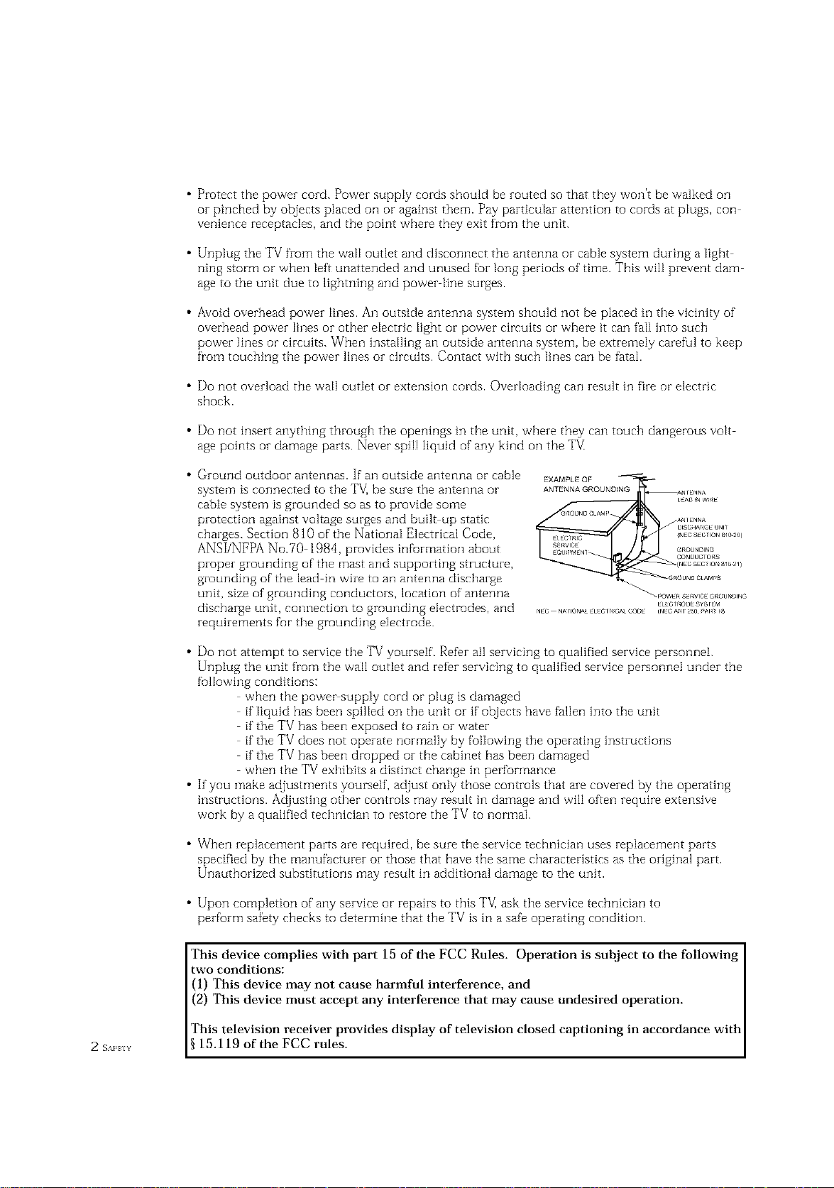
• Ground outdoor antennas. If an outside antenna or cable
system is connected to the TV_ be sure the antenna or
EXAMPLEQF
ANTENNAGROUNDING
cable system is grounded so as to provide some
protection against voltage surges and built up static
charges. Section 810 of the National Electrical Code,
ANSI/NFPA No.70 1984, provides infurmation about
proper grounding of the mast and supporting structure,
grounding of the lead in wire to an antenna discharge
unit, size of grounding conductors, location of antenna
discharge unit, connection to grounding electrodes, and
requirements for the grounding electrode.
• Do not attempt to service the TV yourself. Refer all servicing to qualified service personnei.
Unplug the unit from the wall outIet and refer servicing to qualified service personnel under the
fullowing conditions:
when the power supply cord or plug is damaged
if liquid has been spilIed on the unit or if objects have fallen into the unit
if the TV has been exposed to rain or water
if the TV does not operate normally by following the operating instructions
if the TV has been dropped or the cabinet has been damaged
when the TV exhibits a distinct change in performance
• If you make adjustments yourself, adjust only those controls that are covered by the operating
instructions. Adjusting other controls may result in damage and will often require extensive
work by a qualified technician to restore the TV to normal.
• When replacement parts are required, be sure the service technician uses replacement parts
specified by the manufacturer or those that have the same characteristics as the original part.
Unauthorized substitutions may result in additional damage to the unit.
• Upon completion of any service or repairs to this TV] ask the service technician to
perform safety checks to determine that the TV is in a safe operating condition.
This device complies with part 15 of the FCC Rules. Operation is subject to the following
two conditions:
(1) This device may not cause harmful interference, and
(2) This device must accept any interference that may cause undesired operation.
This television receiver provides display of television closed captioning in accordance with
2 s_._ 15.119 of the FCC rules.
FCC Information
User Inst_uctions
The Federal Communications Commission Radio
Frequency Interference Statement includes the fbllow
ing warning:
NOTE: This equipment has been tested and found to
comply with the limits for a Class Bdigital device, pur
suant to Part 15 ofthe FCC Rules. These limits are
designed to provide reasonable protection against harm
ful interference in a resklential installation This equip
ment generates, uses, and can radiate radio f]-equency
energy and, if not installed and used in accordance with
tile instructions, may cause harmful interference to
radio communications However, there is no guarantee
that interfl_rencewill not occur in a particular installa
tion
If this equipment does cause harmful interference to
radio or television receptions, which can be determined
by turning the equipment off and on, the user is
encouraged to try to correct the interference bk one or
more of the following measures:
• Reorient or relocate tile receiving antenna.
• Increase the separation between the equipment and
r€,coiv€,r.
• Connect the equipment into an outlet on a circuit dif
if,rent fiom that to which the receiver is connected
• Consult the dealer or an experienced radio/TV tech
nician fbr help
User Information
Changes or modifications not expressly approved by the
party responsible fur compliance could void the user's
authority to operate the equipment
If necessary, consult your dealer or an experienced
radio/television technician for additional suggestions.
You may find the booklet called How to Identify and
Resolve Radio/TV Interferc,nce Problems helpful This
booklet was prepared by the Federal Communications
Commission It isavailable from the US. Government
Printing Office, Washington, DC 20402, Stock Number
004000003454
Warning
User I"flLIStuse shielded signal interface cables to
maintain FCC compliance for the product.
Declaration of conff>rmityff>rproducts marked with
FCC Logo This device complies with Part 15 of the
FCC Rules.
Operation is suf£iect to the fbllowing two conditions:
(1) this device may not cause harmful interff,rence, and
(8) this device must accept any interference received,
including interference that may cause undesired opera-
tion
The party responsible for product compliance:
SAMSUNG ELECTRONICS CO, LTD
America QA Lab of Samsung
85 West Tasman Drive
San Jose, CA 95134 USA
%1) 4085445124
Fax) 40854451{)1
Provided with this monitor is a detachable power sup
ply cord with IEC320 style terminations It may be
suitable for connection to any UL Listed personal corn
puter with similar configuration Before making the
connection, make sure the voltage rating of the comput
er convenience outlet is the same as the IllonitoF and
that the ampere rating of the computer convenience
outlet isequal to or exceeds the monitor voltage rating
For 120 Volt applications, use only UL Listed detach
able power cord with NEMA configuration 515P type
(parallel blades) plug cap. For 240 Volt apphcations use
only ULListed Detachable power supply cord with
NEMAconfiguration B015P type (tandem blades) plug
cap
IC Compliance Notice
This Class B digital apparatus meets al]requirements of
the Canadian Interfhrence Causing Equipment
Regu]ations of ICES-003.
Notice de Confbrmit6 IC
Cet apparefl numerique de c]asse B respecte toutes ]es
exigences du Rt,glement ICES 003 sur les equipements
produisant des interforences all Canada
MPR II Compliance
This monitor complies with SWEDAC (MPRII)
recommendations for reduced electric and magnetic
fields.
European Notice
Products with the CE Marking compIy with both the
EMC Directive (89/336/EEC), (92/31/EEC),
(93/68/EEC) and the Low Voltage Directive
(73/23/EEC) issued by the Commission of the European
Community, Compliance with these dFectives implies
confbrmity to the fbllowing European Norms:
• EN55022 (CISPR22) Radio Frequency Interference
• EN50082 1 : 1992 Electromagnetic Immunity
• EN60555 2 (IEC555 2) Power Line Harmonics
• EN605553 (IEC555 3) Voltage Fluctuations
• EN60951) (IEC950) Product Safetk.
SAFFgY
CONTENTS ]
Chapter 1: Your New TV ............... 1.1
List of Featuzes ......................................... 1,1
Familiarizing Yuursetf with Yuuz New TV ..................... 1.2
Front Pane[ Buttons .............................. 1.2
Front Pane[ Jacks ................................ 1,3
Rear Pane[ Jacks ................................. 1.4
Remote Control ................................. ] ..5
Chapter 2: Installation ................ 2.1
Connecting VHF and UHF Antennas ........................ 2.1
Antennas with 300 ohm Flat 7[vin Leads .............. 2.1
Antennas with 75 ohm Round Leads ................. 2.2
Separate VHF and UHF Antennas .................... 2.2
Connecting Cable TV .................................... 2.2
Connecting a VCR ...................................... 2.,5
Connecting a Camcorder ................................. 2.6
Connecting a DVD (480i, 480p) Playez ...................... 2.7
Connecting a DTV Set Top Box (480p, 10800 ................. 2.8
Connecting Surzound Speakers ............................ 2.8
Installing Battezies in the Remote Control ..................... 2.9
Cable without a Cable Box ......................... 2.2
Connecting to a Cable Box that Descramb[es
All Channels .................................... 2.3
Connecting to a Cable Box that Desczamb[es
some Channels .................................. 2.3
Connecting a Second VCR to Record from the TV ....... 2.6
1 (ION] EN] S
Chapter 3: Operation .................. 3.1
Turning tile TV On and Off'................................ 3.1
Plug & Play Featuze ..................................... 3.1
Using the PezfVctFocus Feature ............................ 3.3
Adjusting Manual convergence ............................. 3.4
Adjust Red Convergence .......................... 3.5
Viewing the Menus and On Sczeen Displays ................... 3.6
Viewing the Menus ............................... 3.6
Viewing the Display .............................. 3.6
Selecting a Menu Language ................................ 3.7
Selecting the Antenna Input ............................... 3.7
Memozizing the Channels ................................. 3.8
Selecting the Video Signal source .................... 3.8
StoIing Channels in Memozy (Automatic Method) ....... 3.9
Adding and Ezasing Channels (Manual Method) ........ 3.9
Changing Channels ..................................... 3.10
Using the Channel Buttons ......................... 3.10
Using the Number Buttons ......................... 3.10
Using the Previous Channel ........................ 3.10
Selecting Yuur Favozite Channels ........................... 3.11
To Store Your Favozito Channets: .................... 3.11
To View Youz Favorite Channels: .................... 3.11
Setting the Blue Screen Mode .............................. 3.12
Labeling the Channels ................................... 3.13
Pictuze Control ......................................... 3.14
Customizing the Pictuze ........................... 3.14
Using Automatic Pictuze Settings .................... 3.1,5
Selecting the Color Tone ........................... 3.1B
CONTENTS
Chapter 3: Operation (Cont.) .......... 3.14
Sound Control ......................................... 3.16
Adjusting the Vulume ............................. 3.16
Using Mute ..................................... 3.16
Customizing the Sound ........................... 3.17
Using Automatic Sound Settings .................... 3.18
Setting the Clock ....................................... 3.19
Option 1: Setting the Clock Manually ................ 3.19
Option 2: Using the Local PBS Channel to Automatically
Set the TV Clock ................................ 3.20
Selecting a Signal Source (External A_') ...................... 3.21
Chapter 4: Special Features ............ 4.1
Fine Tuning Channels .................................... 4.1
Digital Noise Reduction .................................. 4.2
Changing the Screen Size ................................. 4.3
Using the R.surf Feature .................................. 4.4
Setting the On/Off Timer ................................. 4.5
Setting the Sleep Timer ................................... 4.(5
Dolby Surround ........................................ 4.7
Choosing a Multi Channel Sound (MTS) track ................. 4.8
Auto Vutume ........................................... 4.9
Viewing Closed Captions ................................. 4. l0
Viewing Picture in Picture ................................ 4.11
Activating Picture in Picture ........................ 4.11
Selecting a Signal Source (Antenna ol-Cable) fur PiP ..... 4.12
Selecting a Signal Source (External A/V) for PIP ......... 4.12
Swapping the Contents of the PIP image and Main image . 4.13
Changing the Size of the PIP Window ................ 4.13
Changing the PIP Channel ......................... 4.14
Changing the Location (Rotating) the PIP mode ......... 4.14
Scanning the Available Channels .................... 4.14
Using the VChip ....................................... 4.15
Setting Up Your Personal ID Number (PIN) ............ 4.15
How to Enable/Disable the VChip ................... 4.16
How to Set up Restrictions Using the "TV guidelines" . . .. 4.1 (5
How to Set up Restrictions using the MPAA Ratings:
G, PG, PG 13, R, NC 17, X ........................ 4.18
How to Reset the TV after the VChip Blocks
a Channel ("Emergency Escape") .................... 4.19
Customizing Yuur Remote Control .......................... 4.20
Setting Up Your Remote Control to Operate Yuur
VCR oi DVD ................................... 4.20
Setting Up Your Remote Control to Operate Yuur
Cable Box...................................... 4.21
Chapter 5: Troubleshooting ............ 5.1
Identifying Pi-oblems .................................... 5.1
Appendix ........................... A.1
Cleaning and Maintaining Yuur TV.......................... A.1
Using Yuur TV in Another Country ......................... A.1
Specifications .......................................... A.1
( _H_H_s 2
YOUR NEW TV
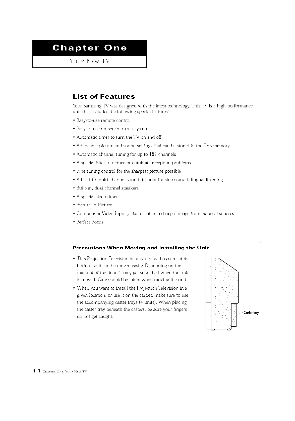
List of Features
Your Samsung TV was designed with the latest tecbnoloz_v This TV is a high perfurmance
unit that includes the following special features:
Easy to use remote control
Easy to use oil screen menu system
Automatic timer to turn the TV oil and off
Adjustable picture and sound settings that can be stored in the TV_ memory
Automatic channel tuning for up to 181 channels
A special filter to Feduce or eliminate reception problems
Fine tuning control fur tile sharpest picture possible
A built in multi channel sound decoder fop stereo and bilingual listening
Built in, dual channel speakers
A special sleep timer
Picture in Picture
Component Video Input jacks to obtain a sharper image from external sources
Perfect Focus
Precautions When Moving and Installing the Unit
This Projection Television is provided with casters at its
bottom so it can be moved easily. Depending oil the
material of the floor, it may get scratched when the unit
is moved. Care should be taken when moving the unit.
When you want to install the Projection Television in a
given location, or use it oil the carpet, make sure to use
the accompanying caster trays (4 units)• When placing
the caster tray beneath the casters, be sure your fingers
do not get caught.
Ca_r tray
1._ (]HAP I ON} Yot}l N]\% V
I Your NEw TV
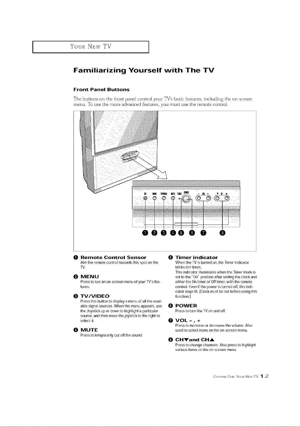
Familiarizing Yourself with The TV
Front Panel Buttons
The buttons on the front panel control your TV_ basic features, including the on screen
menu. Tt_use the more advanced features, you must use the remote control.
y
ii i i
0
Remote Control Sensor
Aim the remote control towards this spot on the
TV.
MENU
0
Press to see an on screen menu o[ your TV's [ea-
tures,
0
TV/VIDEO
Pressthis button to display a menu of all the avail
able signal sources. When the menu appears, use 0
the Joystick up ordown to highlight a particular
source, and then move the joystick to the right to
select it,
0
MUTE
Presstotemporadlycutoffthe sound,
0
Timer indicator
When the TV isturned on, the Timer indicator
blinks ten times.
This indicator illuminates when the Timermode is
set to the" On" position after setting the clock and
either the Ontimer or Off timer, with the remote
control Even if the power is turned off, this indi_
cator stays lib (Clock must be set before using this
function,)
POWER
PresstoturntheTVonandoff.
VOL-, +
Press to increase or decFease the volume. Also
used to select items on the on screen Fllenu.
0
CH_'and CHA
Press to change channels, Also press to highlight
various items on the on screen menu.
Your NEw TV ]
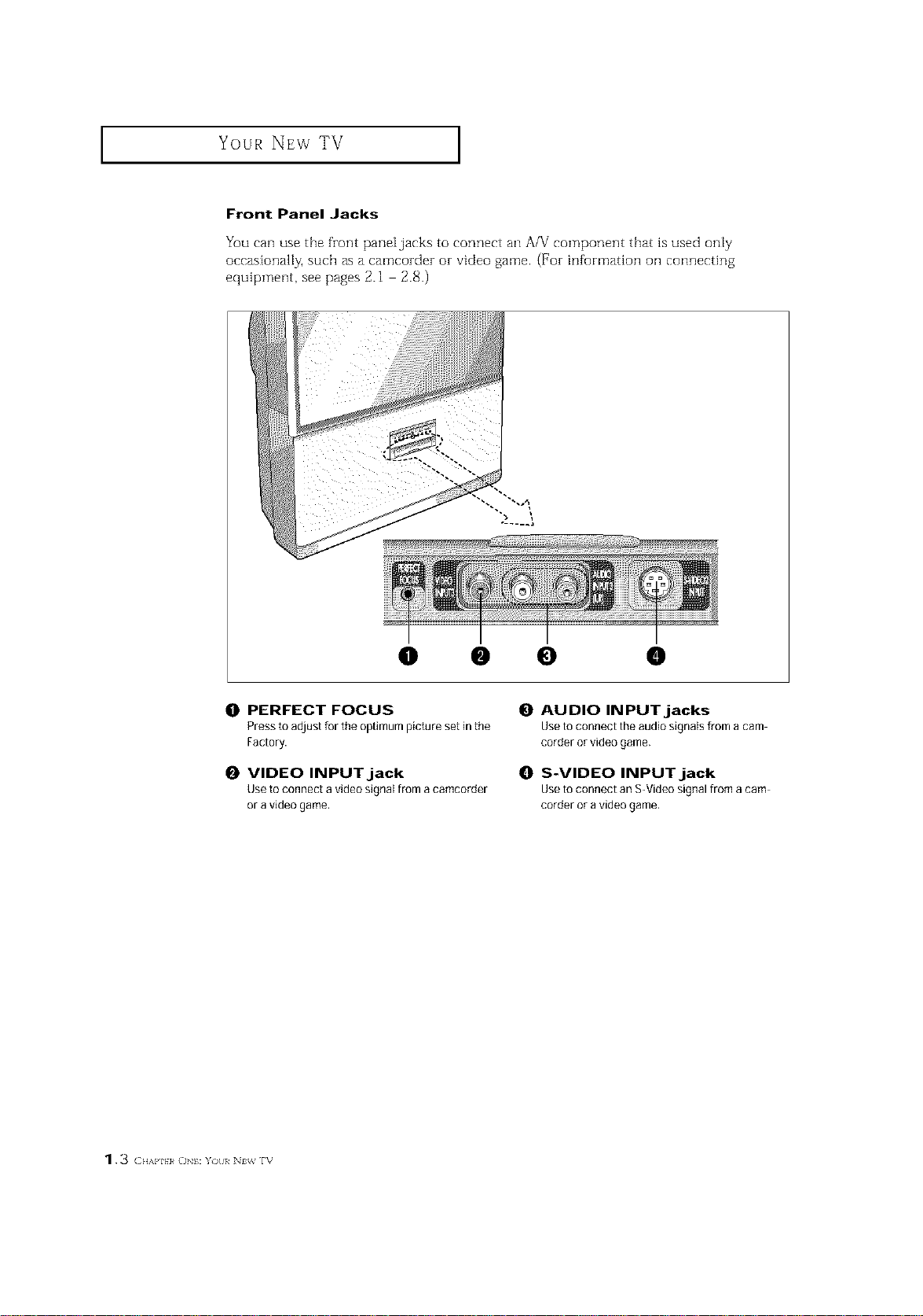
Front Panel Jacks
You can use the fzont pane[jacks to connect an A/V component that is used only
occasionally, such as a camcozdez oz video game. (Foz information oil connecting
equipment, see pages 2.1 2.8.)
I
...... a
0 • 0 •
0 PERFECT FOCUS
Press to adjust for the optimum picture set in the
Factory.
0 VIDEO INPUT jack
Use to connect a video signal from acamcorder
or a video game.
0 AUDIO INPUT jacks
Use to connect the audio signals from a cam
corder or video game.
0 S-VIDEO INPUT jack
Use to connect an S-Video signal from a cam
corder or avideo game.
1.3 (}HAI'I}}_ ()NI: Y )/)l/ lt_ rv

Your NEw TV ]
Rear Panel Jacks
Use the zear parle] jacks to connect an A/V component that will be connected conthlu
ously, such as a VCR or a DVD player.
Because theze are two sets of inputjacks, you can connect two different A/V components
(i.e., a VCR and a DVD, 2 VCRs, etc.)
For more inf_rmation oil connecting equipment, see pages 2.1 2.8.
\
() ANTENNA terminals 0
Two independent cables or antennas can be
connected to these terminals, Use ANT-A and
ANTB terminals to receive a signal from
VHHUHFantennas or your cable system. Use
the ANTA OUTterminal to send the signal being
received by the ANnA terminal out to another
component (such as a Cable Set TopBox), The O
PiP channel can be received only when a signal
source is connected to ANT A.
O
S-VIDEO INPUTjack
Connectto an S VHSVCRorDVDplayer,
O
VIDEO INPUTjacks
Connect to the video outputjacks of VCRs,DVD
players and similar devices (Twosets are avail
abie: Video1 andVideo2),
O AUDIO INPUTjacks
Connect to the audio outputjacks ofVCRs,DVD
players and similar devices.
AUDIO-VIDEO MONITOR
OUTPUT jacks
Connect to the audio/video inputjacks of a
recording VCR,
Note: The monitor out does notoperate in DVD
or DTVmode.
COMPONENT 1(480i, 480p)
INPUT jacks
Connecta sourcethatoutputs480i/480pY.P,and
P_signals,suchasaDVDPlayer.
O
COMPONENT 2(480p, 1080i)
INPUT jacks
Connecta sourcethatoutputs480p/t080iY.P,_
andP_signals,suchasa DTVSet:fopBox.
O
SURROUND OUT
Connects to a (optional) rear surround amp:
Surround Left, Surround Rightand Center.
Your NEw TV ]
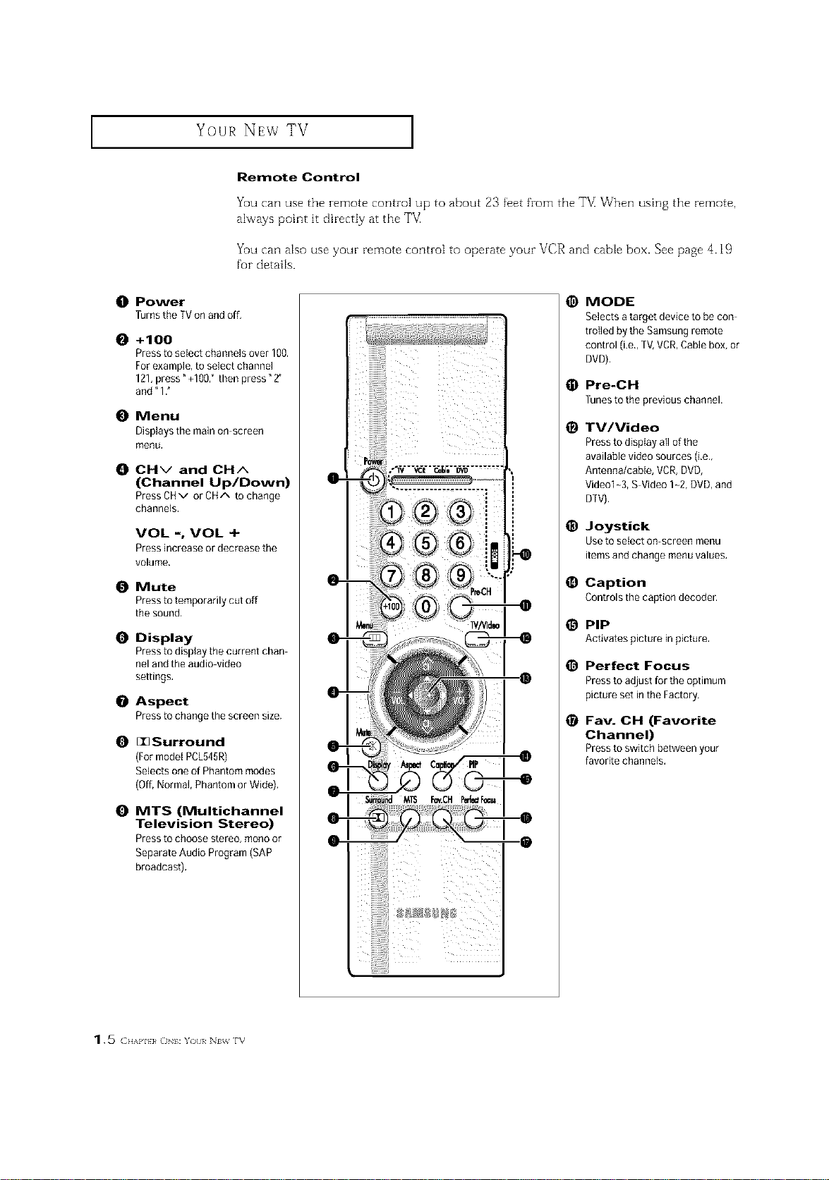
Remote Control
Yuu can use the remote control up to about 23 feet from the T_ When using the remote,
always point it directly at the T_
You can also use your remote control to operate your VCR and cable box. See page 4.19
for details.
O Power
Turns the TVon and off,
O +100
Pressto select channels over 100.
For example, to select channel
121,press" +100," then press" 2"
and" 1."
O Menu
Displays the main on screen
menu,
O CHv and CHA
(Channel Up/Down)
Press CHv or CHA to change
channels,
VOL -, VOL +
Press increase or decrease the
volume.
Mute
Pressto temporarily cut off
the sound,
O Display
Pressto display the current chan
nel and the audio video
settings.
Aspect
Pressto change the screen size.
O I1_ Surround
(Formodel PCL545R)
Selects oneof Phantom modes
(Off,Normal, Phantom or Wide),
@
MODE
Selects atarget device to be con
trolled by the Samsungremote
control (i.e.,TV,VCR,Cable box, or
DVD),
Pre-CH
@
Tunestothepreviouschannel.
TV/Video
@
Pressto display all of the
available video sources (i,e,,
Antenna/cable, VCR, DVD,
Vide@l-3, S Video 1-2, DVD, and
DTV).
@
Joystick
Use to select on-screen menu
items and change menuvalues.
O
Caption
Controlsthecaptiondecoder.
PIP
@
Activatespictureinpicture,
e
Perfect Focus
Pressto adjust for the optimum
picture set inthe Factory.
o
Fav. CH (Favorite
Channel)
Pressto switchbetweenyour
favoritechannels.
O MTS (Multichannel
Television Stereo)
Pressto choose stereo, re@noor
Separate Audio Program (SAP
broadcast).
1.5 ( ..,,p. _o :Y)tl/ N_ rv

I Your NEw TV
Remote Control (continued)
ANT A/B
Press to select the ANT A or ANT
B,
R.surf
Press to automatically return to a
preferred charnel after a user
preset time delay.
S.Mode
Adjust the TVsound byselecting
oneof the preset factory settings
(or select your personal, cus
tomized sound settings),
P.Mode
Adjust the TVpicture byselect
ing one of the preset factory set
tings (or select your personal,
customized picture settings),
VCR controls
Controls VCRtape functions:
Rewind, Play, fast Forward, Stop,
Pause.
PiP Controls
Source
Press to select one of the avail
able signal sources for the PIP
window,
Scan
Press to memorize (scan)the
available channels,
Locate
Press to move the PIP window to
any of the four corners of the TV
screen,
V.chip
Press to set upand activate the
parental locks.
Set
@
Used during set up ofthis
Samsung remote control, sothat
it will work compatibly with
other devices (VCR,cable box,
DVD.)
@
Sleep
Press to select a preset time
interval for automatic shutoff,
Add/Erase
Press to add orerase channels
in the TV's memory,
Exchangesthe video signal that
is currently displayed on the
main screen with the signal in
the PIP window,
Size
Press to make the PIP window
small, large or double screen,
• Double window doesn't func
tion on the models
PCL5415R!PCL6215R.
614
Displays the available channels
in sequence, (Thesebuttons
change channels in the PIPwin
dow only).
C]I_P ii ON}: Yot}}_ NI;_ IV 1.6
INSTALLATION
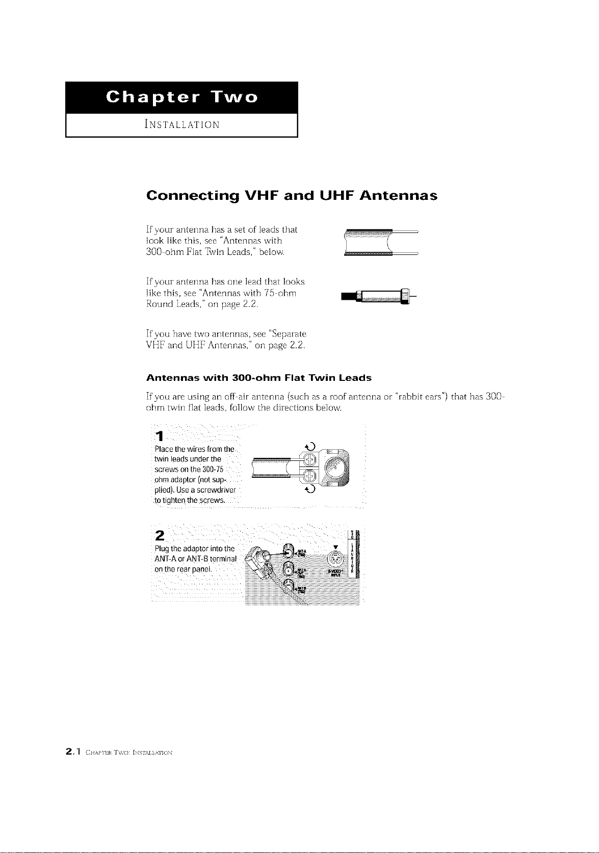
Connecting VHF and UHF Antennas
If youz antenna has a set of leads that
look like this, see "Antennas with
300 ohm Flat _vin Leads," below.
If youz antenna has one lead that looks
like this, see "Antennas with 75 ohm
Round Leads," oil page 2.2.
If you have two antennas, see "Separate
VHF and UHF Antennas," oil page 2.2.
Antennas with 300-ohm Flat Twin Leads
If'you aze using an off air antenna (such as a zoof antenna or "zabbit eazs") that has 300
ohm twin fiat leads, follow the dizections below.
Place the W-eS from the
[win leads under the
screws on the 300-75
_hm ada D[OFirlo[ Sill3
JIiedl Use a screwdriver
[o i _rt[en the scows
2
INSTALLATION ]
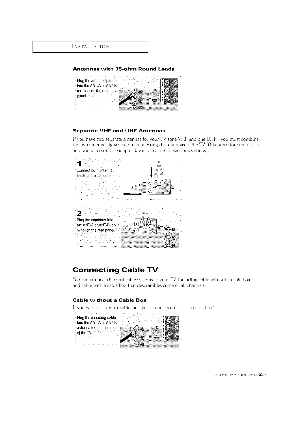
Antennas with 75-ohm Round Leads
Plugthe antenna lead
into the ANTRAor ANT-B
terminal onthe rear
Separate VHF and UHF Antennas
If you have two separate antennas for your TV (one VHF and one UHF), you must combine
the two antenna signals before connecting the antennas to the FM This procedure requh-es a
an optional combiner-adaptor (available at most electronics shops).
Connect bot- antenna
eads to the combiner,
2
)lugthecombinerinto
Connecting Cable TV
You can connect different cable systems to youz TV, inciuding cable without a cable box,
and cable with a cable box that descrambles some oi- all channels.
Cable without a Cable Box
If you want to connect cable, and you do not need to use a cable box:
Plugthe incoming cable
into the ANT-A or ANT-B
antenna terminal on rear
(} I,\P] _ _( / ]NSIAI AI( /N 2 * 2

INSTALLATION ]
Cable with a Cable box that Descrambles All Channels
1
connected[indthe cabletothethatis
NT NNA T rmn
A E 0U te a
onyourcablebox,This _r_
terminalmightbe
CoaRect the other end of
ths cable to the ANTRA
or ANT-Bterminal onthe
rear of the TV,
Connecting to a Cable Box that Descrambles Some Channels
If your cable box descrambles orgy some channels (such as premium channels), fullow the
instructions below. You will need a two way splitter, an RF (A/B) switch, and fuur lengths of'
coaxial cable. (These items are available at most electronics stores.)
This terminal might be labeled
qndandd_sconnectthe
Cable tllat _s connected N_rn_NA
totheANTENNAINter- Z_=_ 0 IN
miRal OR your CaDIe bOA,
"ANT IN," "VI [F IN," or simply,
"IN."
2, 3 (IIAP] I IV(} ]NSI\IIAI/)N
2
CoRRectthis cable [o a
[wo_way spl tier,
3
Connect a coaxial cable
3etween an OUTPUTter
"nmalonthe s_ rter an_
the INterminai onthe
cable box.
neomleg
n_rrllrlg
Cable
SplRter
CableBox

INSTALLATION ]
Connect a coaxial cable r_[_lFI
betweentheANTENNA _1 I_
OUTterminal onthe Cableg _ _
cable box and the B_IN Splitter RF(NB)
terminai onthe A/B CableBox Swffch
Connect another cable _
between the other OUT
terminal onthe splitter Incoming
and the A* INterminal on ¢,a_D Splffler RF(A/B)
the RF(A/B) switch. _ble Box sw_h
Connect the last coaxi_
cable between the OUT Incoming
terminal onthe RF(A/B) Cable
switch and the VHF/UHE
terminal onthe rear of
the TV.
. Incoming
CableBox
After you've made this connection, set the A/B switch to the "A" position fur normal view
ing. Set the A/B switch to the "B" position to view scrambled channels. (When you set the
A/B switch to "B," you will need to tune your TV to the cable box_ output channel, which is
usually channel 3 oi- 4.)
(} l,\P] 1%%( ) ]NSIAI AII( )N 2,4
INSTALLATION ]
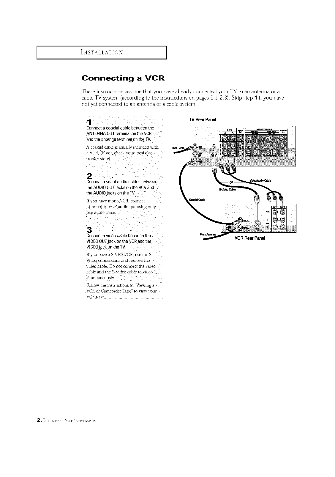
Connecting a VCR
These instructions assume that you have already connected your TV to an antenna or a
cable TV system (according to the instructions oil pages 2.1 2.3). Skip step 1 if you have
not yet connected to an antenna or a cable system.
TV RearPanel
Connect a coaxial cable between the
ANTENNA OUTterminal on the VCR
andthe antenna terminal on the IV.
A coaxial cable is usua]lj ixlcluded wire
_VCR Ifilot. nec_yourlocalele_
[o[ liCE $1 o_-e
2
Conqect a set of audio cabies between
the AUDIO OUTjacks on the VCRand
the AUDIOjacks on lhe TV
if you flare znoIlc VCR om_ec[
Limono} to VCR audio out using o_fly
o[_e audio cable
:3
Connect a video cable between the
VIDEO OUTjack on the VCR and the
VIDEOjack on the TV
if you ha_e a S-VIlE VCR use the S-
Video cOiiFleCliofls ai_d _emove lbe
vlcleo _ble. Do ncl[ coi-_i_ecl trle video
cable axxd the S-Video cable _o video 1
_11nullaileous]_
[to]low the lns[i uclions in "Viewiilg a
VCR o_ Camco_der Tape to wew ) _u*
VCR/ape.
VCRRearPanel
2,5 (I{AP] I _v() INS \l],\ {_N
I I
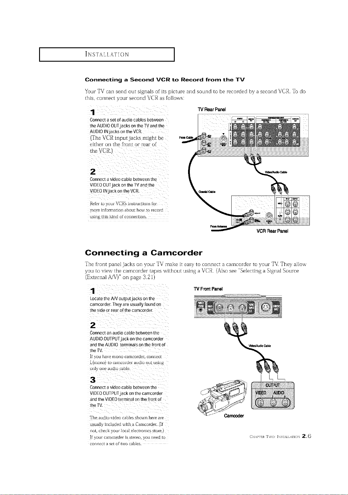
Connecting a Second VCR to Record from the TV
Your TV can send out signals of its picture and sound to he recorded by a second VCR. To do
this, connect your second VCR as follows:
Connect a set of audio cables between
the AUDIO OUTjacks on the TVand the
AUDIO INjacks on the VCR.
(The VCR input,jacks might be
either on the front or rear of'
Connect a video cable between the
VIDEOOUTjack on the TVand the
VIDEO INjack on the VCR,
more information abou[ how to record
l'V Rear Panel
VCRRearPanel
Connecting a Camcorder
The front panel jacks on your TV make it easy to connect a camcorder to your TV[ They allow
you to view the camcorder tapes without using a VCR. (Also see "Selecting a Signal Source
(External A/V)" on [)age 3.21)
1
Locate the A/V outputjacKs on me
camcorder, Theyare usua_q found 3n
the side or rear of the camcoraer,
"i3/Front Panel
2
Connect an audio cable between me
AUDIO OUTPUIjack onthe camcorder
andthe AUDIO terminals on the front of
the [
[fyOU l-_2tV_ r:fiO[lO C_rI"ICOI-GeI. COIIIIpC[
L{mo[lc to ramcoidez audio ou[ using
o1_1_ o1_ alJCl[O cable
3
Connect a videocable between the
VIDEOOUTPUTjack on the camcorder
andthe VIDEOterminm on me front of
the I
TR_ allQlO_ ldPo c3bles shown h_iP _iiP
usuall3 included with aCamcomei ]f
1lOt CYI_C[_ g OIlI IcIca] PI_¢t[OYlI{ _ S[OI_
[t yOU[ [ aIIiCOI dP[ is S[_i_o C)tl Ile_[_ [(
COIIKI_C[ a S_[ Of [VVO caDI_
INSTALLATION ]
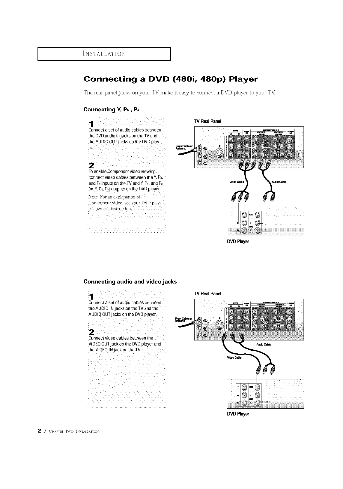
Connecting a DVD (480i, 480p) Player
The rear pand jacks on your TV make it easy to connect a DVD player to your T_
Connecting Y, P., P.
TVRe= Panel
Connect a set of audio cabies between
the DVD audio injacks on the TVand
the AUDtO OUTjabkS on the DVD ptay-
er,
Toenable Component video viewing,
connect video cables between the Y, PB,
and Pkinputs on the TVand Y,P_,and P_
(or Y,C_,C,_)outputs onthe DVDplayer,
Connecting audio and video jacks
Connect a set of aumo caoies Between
the AUDIO INjacks on the TVand the
AUDIO OUTjacks on the DVD player.
2
Connect video cables between the
VIDEOOUTjack on the DVDplayer and
the '_ DEOINjack on the TV.
DVDPlayer
TVRe_ Panel
2.7 (IIAPJTI _'_'(} INS \I]A /JN
DVDPlayer
INSTALLATION ]
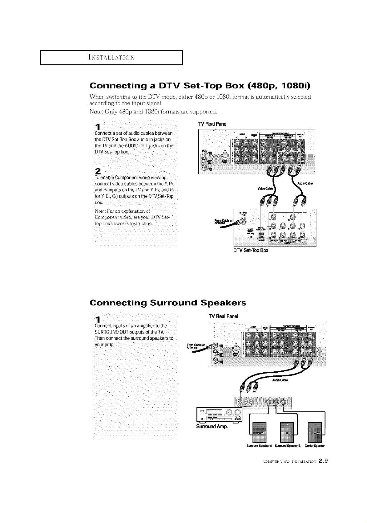
Connecting a DTV Set-Top Box (480p, 1080i)
When switching to the DTV mode, either dS0p oi- 1080i format is automatically selected
according to the input signal.
Note: Only 480p and 1080i formats are supported.
TVRealPanel
Connect a set of audio cables between
the DTVSet:top Box audio injacks on
the [V andthe AUDIO OUTjacks on the
DTVSet:top box_
2
Toenable Component videoviewing.
connect video cables between the Y.Ps.
and PJ_inputs onthe [V and Y,Ps.and P_
(or Y.CB.C,)outputs on the DTVSetTTop
box.
Note: I?oran explanation of
Component video, see you; lgTV Sei-
top box's ow'ner_ instruction.
Connecting Surround Speakers
1
Connect incurs of an ampIifier to the
SURROUNDOUToutou[s ofthe _f
Thenconnect me surrouna soeakers to
your amp
"IVRealPanel
SunoundAmp.
DTVSet-T0pBox
Surround_eaksrA _lr_l_d,_B CentsrSpealmr
(} I,\P] l _( / ]NSIAI AlL /N 2.8
 Loading...