

Samsung PCJ534RF3C, PCJ534RFX, PCJ614RF3C service manual
PROJECTION TV RECEIVER
Chassis : P51A (REV. 1)
Model : PCJ534RF3C/XAA PCJ534RFX/XTC
PCJ614RF3C/XAA
PROJECTION TV RECEIVER CONTENTS
Precautions
Reference Information
Specifications
Alignment and Adjustments
Troubleshooting
Exploded View and Parts List
Electrical Parts List
Block Diagrams
Wiring Diagram
Schematic Diagrams
1.
2.
3.
4.
5.
6.
7.
8.
9.
10.

ELECTRONICS
© Samsung Electronics Co., Ltd. JUL. 2000
Printed in Korea
3P51A-6510
1. Precautions
1-1 Safety Precautions
1. Be sure that all of the built-in protective
devices are replaced. Restore any missing
protective shields.
2. When reinstalling the chassis and its
assemblies, be sure to restore all protective
devices, including: nonmetallic control knobs
and compartment covers.
3. Make sure that there are no cabinet openings
through which people—particularly
children—might insert fingers and contact
dangerous voltages. Such openings include
the spacing between the picture tube and the
cabinet mask, excessively wide cabinet
ventilation slots, and improperly fitted back
covers.
If the measured resistance is less than 1.0
megohm or greater than 5.2 megohms, an
abnormality exists that must be corrected
before the unit is returned to the customer.
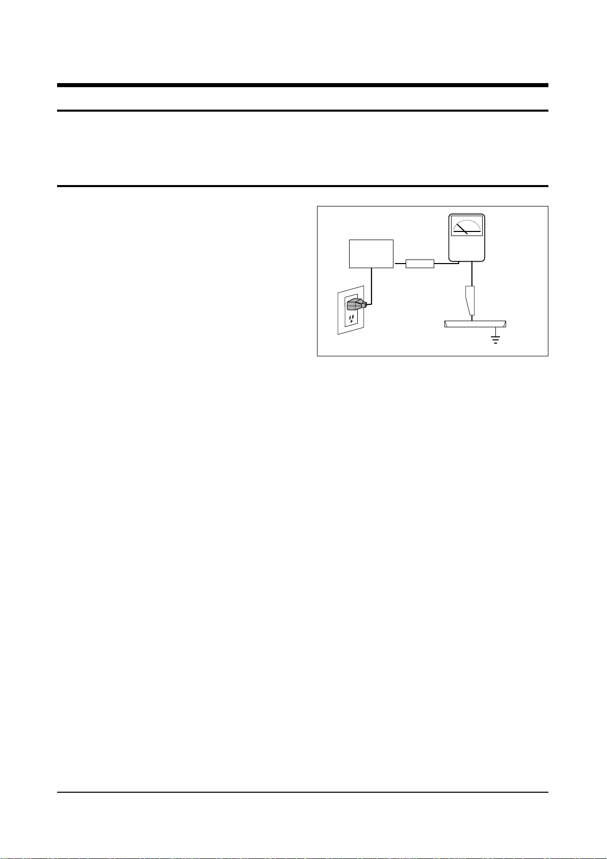
4. Leakage Current Hot Check (Figure 1-1):
Warning: Do not use an isolation
transformer during this test. Use a leakagecurrent tester or a metering system that
complies with American National Standards
Institute (ANIS C101.1, Leakage Current for
Appliances), and Underwriters Laboratories
(UL Publication UL1410, 59.7).
5. With the unit completely reassembled, plug
the AC line cord directly into the power
outlet. With the unit’s AC switch first in the
ON position and then OFF, measure the
current between a known earth ground (metal
water pipe, conduit, etc.) and all exposed
metal parts, including: antennas, handle
brackets, metal cabinets, screwheads and
control shafts. The current measured should
not exceed 0.5 milliamp. Reverse the powerplug prongs in the AC outlet and repeat the
test.
Fig. 1-1 AC Leakage Test
6. Antenna Cold Check:
With the unit’s AC plug disconnected from the
AC source, connect an electrical jumper across
the two AC prongs. Connect one lead of the
ohmmeter to an AC prong. Connect the other
lead to the coaxial connector.
7. X-ray Limits:
The picture tube is especially designed to prohibit X-ray emissions. To ensure continued
X-ray protection, replace the picture tube only
with one that is the same type as the original.
Carefully reinstall the picture tube shields and
mounting hardware; these also provide X-ray
protection.
8. High Voltage Limits:
High voltage must be measured each time servicing is done on the B+, horizontal deflection
or high voltage circuits. Correct operation of
the X-ray protection circuits must be
reconfirmed whenever they are serviced.
(X-ray protection circuits also may be called
“horizontal disable” or “hold-down”.)
Heed the high voltage limits. These include
the X–ray Protection Specifications Label, and
the Product Safety and X-ray Warning Note on
the service data schematic.
Precautions
Samsung Electronics 1-1
LEAKAGE
CURRENT
TESTER
DEVICE
UNDER
TEST
TEST ALL
EXPOSED METAL
SURFACES
3-WIRE CORD
ALSO TEST WITH
PLUG REVERSED
(USING AC ADAPTER
PLUG AS REQUIRED)
EARTH
GROUND
(READING SHOULD
NOT BE ABOVE
0.5mA)
Follow these safety, servicing and ESD precautions to prevent damage and protect against potential
hazards such as electrical shock and X-rays.

1-1 Safety Precautions (Continued)
9. High voltage is maintained within specified
limits by close-tolerance, safety-related
components and adjustments. If the high
voltage exceeds the specified limits, check
each of the special components.
10. Design Alteration Warning:
Never alter or add to the mechanical or
electrical design of this unit. Example: Do not
add auxiliary audio or video connectors. Such
alterations might create a safety hazard. Also,
any design changes or additions will void the
manufacturer’s warranty.
11. Hot Chassis Warning:
Some TV receiver chassis are electrically
connected directly to one conductor of the AC
power cord. If an isolation transformer is not
used, these units may be safely serviced only
if the AC power plug is inserted so that the
chassis is connected to the ground side of the
AC source.
To confirm that the AC power plug is inserted
correctly, do the following: Using an AC
voltmeter, measure the voltage between the
chassis and a known earth ground. If the
reading is greater than 1.0V, remove the AC
power plug, reverse its polarity and reinsert.
Re-measure the voltage between the chassis
and ground.
12. Some TV chassis are designed to operate with
85 volts AC between chassis and ground,
regardless of the AC plug polarity. These units
can be safely serviced only if an isolation
transformer inserted between the receiver and
the power source.
13. Some TV chassis have a secondary ground
system in addition to the main chassis ground.
This secondary ground system is not
isolated from the AC power line. The two
ground systems are electrically separated by
insulating material that must not be defeated
or altered.
14. Components, parts and wiring that appear to
have overheated or that are otherwise
damaged should be replaced with parts that
meet the original specifications. Always
determine the cause of damage or overheating, and correct any potential hazards.
15. Observe the original lead dress, especially
near the following areas: Antenna wiring,
sharp edges, and especially the AC and high
voltage power supplies. Always inspect for
pinched, out-of-place, or frayed wiring. Do
not change the spacing between components
and the printed circuit board. Check the AC
power cord for damage. Make sure that leads
and components do not touch thermally hot
parts.
16. Picture Tube Implosion Warning:
The picture tube in this receiver employs
“integral implosion” protection. To ensure
continued implosion protection, make sure
that the replacement picture tube is the same
as the original.
17. Do not remove, install or handle the picture
tube without first putting on shatterproof
goggles equipped with side shields. Never
handle the picture tube by its neck. Some
“in-line” picture tubes are equipped with a
permanently attached deflection yoke; do not
try to remove such “permanently attached”
yokes from the picture tube.
18. Product Safety Notice:
Some electrical and mechanical parts have
special safety-related characteristics which
might not be obvious from visual inspection.
These safety features and the protection they
give might be lost if the replacement component differs from the original—even if the
replacement is rated for higher voltage,
wattage, etc.
Components that are critical for safety are
indicated in the circuit diagram by shading,
( ) or ( ).
Use replacement components that have the
same ratings, especially for flame resistance
and dielectric strength specifications.
A replacement part that does not have the
same safety characteristics as the original
might create shock, fire or other hazards.
Precautions
1-2 Samsung Electronics

1-2 Servicing Precautions
1. Servicing precautions are printed on the
cabinet. Follow them.
2. Always unplug the unit’s AC power cord from
the AC power source before attempting to: (a)
Remove or reinstall any component or
assembly, (b) Disconnect an electrical plug or
connector, (c) Connect a test component in
parallel with an electrolytic capacitor.
3. Some components are raised above the printed
circuit board for safety. An insulation tube or
tape is sometimes used. The internal wiring is
sometimes clamped to prevent contact with
thermally hot components. Reinstall all such
elements to their original position.
4. After servicing, always check that the screws,
components and wiring have been correctly
reinstalled. Make sure that the portion around
the serviced part has not been damaged.
5. Check the insulation between the blades of the
AC plug and accessible conductive parts
(examples: metal panels, input terminals and
earphone jacks).
6. Insulation Checking Procedure: Disconnect the
power cord from the AC source and turn the
power switch ON. Connect an insulation
resistance meter (500V) to the blades of the AC
plug.
The insulation resistance between each blade
of the AC plug and accessible conductive parts
(see above) should be greater than 1 megohm.
7. Never defeat any of the B+ voltage interlocks.
Do not apply AC power to the unit (or any of
its assemblies) unless all solid-state heat sinks
are correctly installed.
8. Always connect a test instrument’s ground
lead to the instrument chassis ground before
connecting the positive lead; always remove
the instrument’s ground lead last.
9. When some parts inside the optical engine
(except lamp) are damaged, replace the whole
optical engine.
Precautions
Samsung Electronics 1-3
Warning 1 : First read the “Safety Precautions” section of this manual. If some unforeseen circumstance creates a
conflict between the servicing and safety precautions, always follow the safety precautions.
Warning 2 : An electrolytic capacitor installed with the wrong polarity might explode.

1-3 Precautions for Electrostatically Sensitive Devices (ESDs)
1. Some semiconductor (“solid state”) devices
are easily damaged by static electricity. Such
components are called Electrostatically
Sensitive Devices (ESDs); examples include
integrated circuits and some field-effect
transistors. The following techniques will
reduce the occurrence of component damage
caused by static electricity.
2. Immediately before handling any semicon
ductor components or assemblies, drain the
electrostatic charge from your body by
touching a known earth ground. Alternatively,
wear a discharging wrist-strap device. (Be
sure to remove it prior to applying power—
this is an electric shock precaution.)
3. After removing an ESD-equipped assembly,
place it on a conductive surface such as
aluminum foil to prevent accumulation of
electrostatic charge.
4. Do not use freon-propelled chemicals. These
can generate electrical charges that damage
ESDs.
5. Use only a grounded-tip soldering iron when
soldering or unsoldering ESDs.
6. Use only an anti-static solder removal device.
Many solder removal devices are not rated as
“anti-static”; these can accumulate sufficient
electrical charge to damage ESDs.
7. Do not remove a replacement ESD from its
protective package until you are ready to
install it. Most replacement ESDs are
packaged with leads that are electrically
shorted together by conductive foam,
aluminum foil or other conductive materials.
8. Immediately before removing the protective
material from the leads of a replacement ESD,
touch the protective material to the chassis or
circuit assembly into which the device will be
installed.
9. Minimize body motions when handling
unpackaged replacement ESDs. Motions such
as brushing clothes together, or lifting a foot
from a carpeted floor can generate enough
static electricity to damage an ESD.
Precautions
1-4 Samsung Electronics

Reference Information
Samsung Electronics 2-1
2. Reference Information
2-1 Tables of Abbreviations and Acronyms
A
Ah
Å
dB
dBm
°C
°F
°K
F
G
GHz
g
H
Hz
h
ips
kWh
kg
kHz
kΩ
km
km/h
kV
kVA
kW
I
MHz
Ampere
Ampere-hour
Angstrom
Decibel
Decibel Referenced to One
Milliwatt
Degree Celsius
Degree Fahrenheit
degree Kelvin
Farad
Gauss
Gigahertz
Gram
Henry
Hertz
Hour
Inches Per Second
Kilowatt-hour
Kilogram
Kilohertz
Kilohm
Kilometer
Kilometer Per Hour
Kilovolt
Kilovolt-ampere
Kilowatt
Liter
Megahertz
MV
MW
MΩ
m
µA
µF
µH
µm
µs
µW
mA
mg
mH
mI
mm
ms
mV
nF
Ω
pF
Ib
rpm
rps
s
V
VA
W
Wh
Megavolt
Megawatt
Megohm
Meter
Microampere
Microfarad
Microhenry
Micrometer
Microsecond
Microwatt
Milliampere
Milligram
Millihenry
Milliliter
Millimeter
Millisecond
Millivolt
Nanofarad
Ohm
Picofarad
Pound
Revolutions Per Minute
Revolutions Per Second
Second (Time)
Volt
Volt-ampere
Watt
Watt-hour
Table 2-1 Abbreviations

Reference Information
2-2 Samsung Electronics
Table 2-2 Table of Acronyms
ABL
AC
ACC
AF
AFC
AFT
AGC
AM
ANSI
APC
APC
A/V
AVC
BAL
BPF
B-Y
CATV
CB
CCD
CCTV
Ch
CRT
CW
DC
DVM
EIA
ESD
ESD
FBP
FBT
FF
FM
FS
GND
G-Y
H
HF
HI-FI
IC
IC
IF
Automatic Brightness Limiter
Alternating Current
Automatic Chroma Control
Audio Frequency
Automatic Frequency Control
Automatic Fine Tuning
Automatic Gain Control
Amplitude Modulation
American National Standards Institute
Automatic Phase Control
Automatic Picture Control
Audio-Video
Automatic Volume Control
Balance
Bandpass Filter
Blue-Y
Community Antenna Television (Cable TV)
Citizens Band
Charge Coupled Device
Closed Circuit Television
Channel
Cathode Ray Tube
Continuous Wave
Direct Current
Digital Volt Meter
Electronics Industries Association
Electrostatic Discharge
Electrostatically Sensitive Device
Feedback Pulse
Flyback Transformer
Flip-Flop
Frequency Modulation
Fail Safe
Ground
Green-Y
High
High-Frequency
High Fidelity
Inductance-Capacitance
Integrated Circuit
Intermediate Frequency
I/O
L
L
LED
LF
MOSFET
MTS
NAB
NEC
NTSC
OSD
PCB
PLL
PWM
QIF
R
RC
RF
R-Y
SAP
SAW
SIF
SMPS
S/N
SW
TP
TTL
TV
UHF
UL
UV
VCD
VCO
VCXO
VHF
VIF
VR
VTR
VTVM
TR
Input/output
Left
Low
Light Emitting Diode
Low Frequency
Metal-Oxide-Semiconductor-Field-Effect-Tr
Multi-channel Television Sound
National Association of Broadcasters
National Electric Code
National Television Systems Committee
On Screen Display
Printed Circuit Board
Phase-Locked Loop
Pulse Width Modulation
Quadrature Intermediate Frequency
Right
Resistor & Capacitor
Radio Frequency
Red-Y
Second Audio Program
Surface Acoustic Wave(Filter)
Sound Intermediate Frequency
Switching Mode Power Supply
Signal/Noise
Switch
Test Point
Transistor Transistor Logic
Television
Ultra High Frequency
Underwriters Laboratories
Ultraviolet
Variable-Capacitance Diode
Voltage Controlled Oscillator
Voltage Controlled Crystal Oscillator
Very High Frequency
Video Intermediate Frequency
Variable Resistor
Video Tape Recorder
Vacuum Tube Voltmeter
Transistor
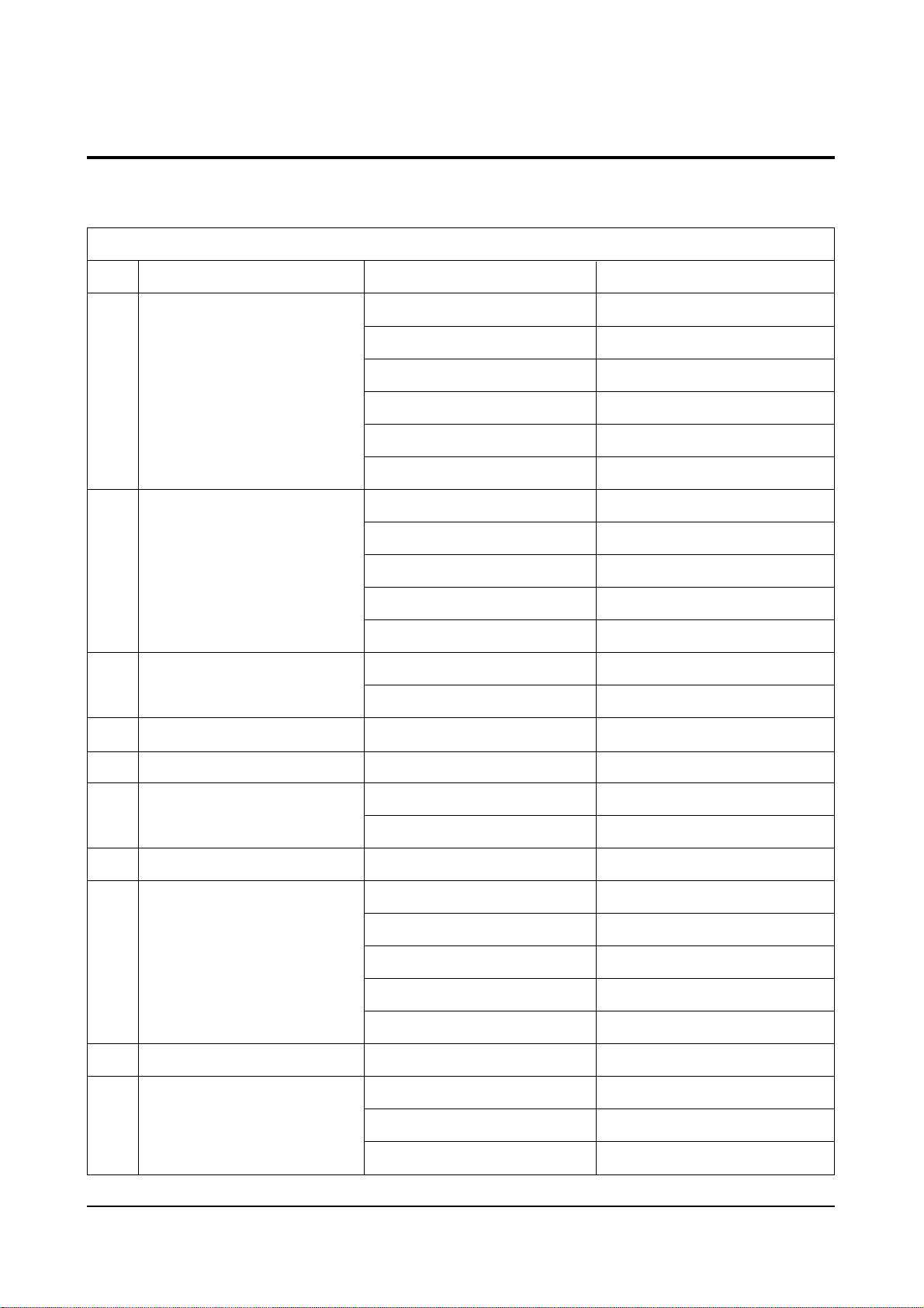
IC507 EL4583CN (OPTION)
IC665 TDA7265
IC904 KS24C04
ICP02 MC14528BCP (OPTION)
ICS801 TNY253P
ICS802 PC123
IC601 TDA7429S
IC602 KA4558
IC905 PCF8574P
ICV01 TA8851BN
ICV02,ICV03 HCF4053BE
ICP01 SDA 9488X
ICP02 4931
IC101 TDA9850
IC101 LA7565B
IC471 TL494CN
IC491 74HC123P
ICZ104,ICZ103 STK392-040
IC301 LA7845
IC801 STR-F6656
IC802 SVD001
IC804 SE110N
IC806 PS2561
IC501,IC531,IC561 TDA6111Q
IC01 UPD 64082GF
IC02 UPC1862GS
IC03 5412222
1
2
3
4
5
6
7
8
9
10
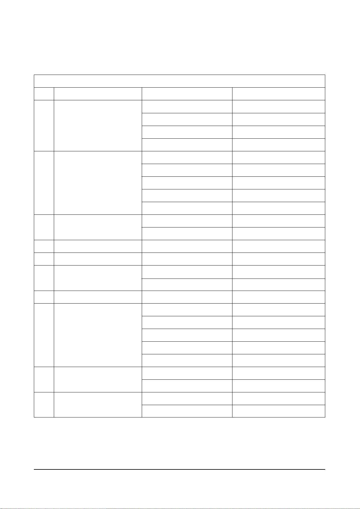
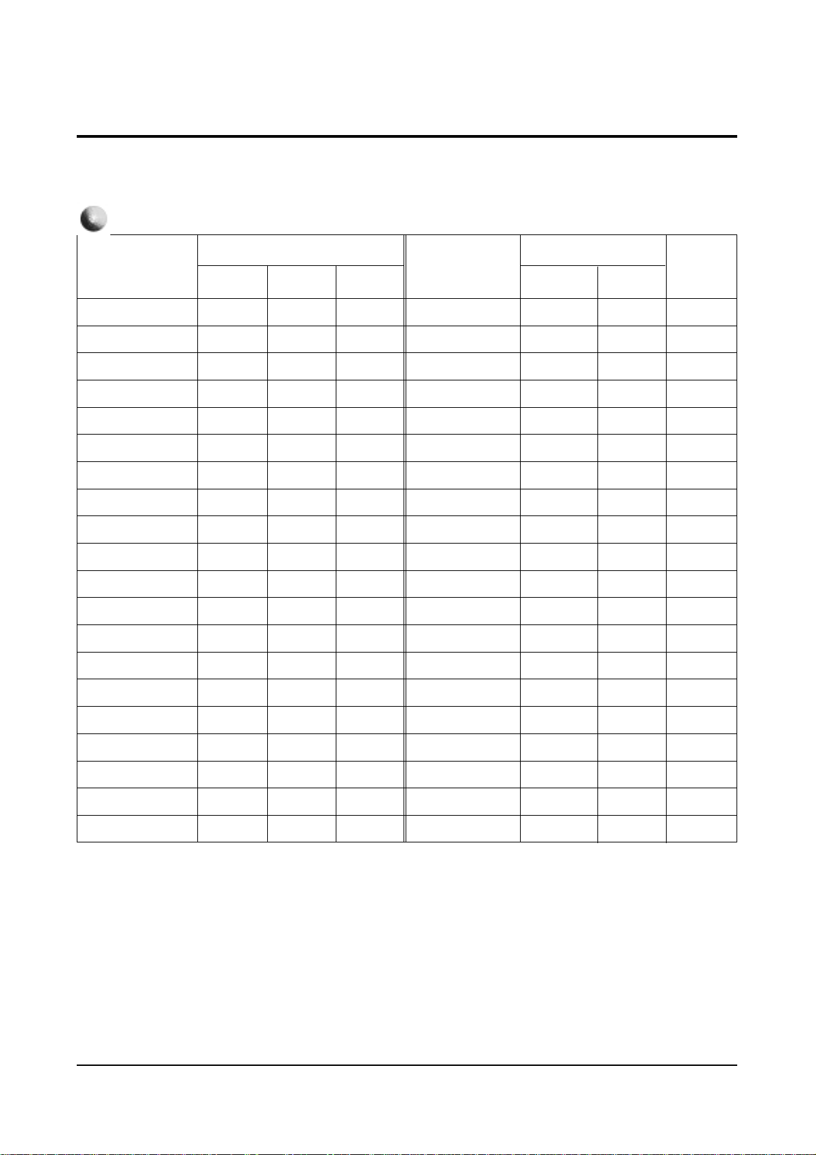
Block NameNo. IC Location IC Name
Table 2 - 3 IC Line - Up
Reference Information
Samsung Electronics 2-3
2-2 IC Line Up
2-2-1 Progressive
MAIN
TERMINAL BOARD
PIP
MTS MODULE
IF MODULE
HV MODULE
CONVERGENCE
SUB
CRT
3D-COMB
Reference Information
2-4 Samsung Electronics
11
12
13
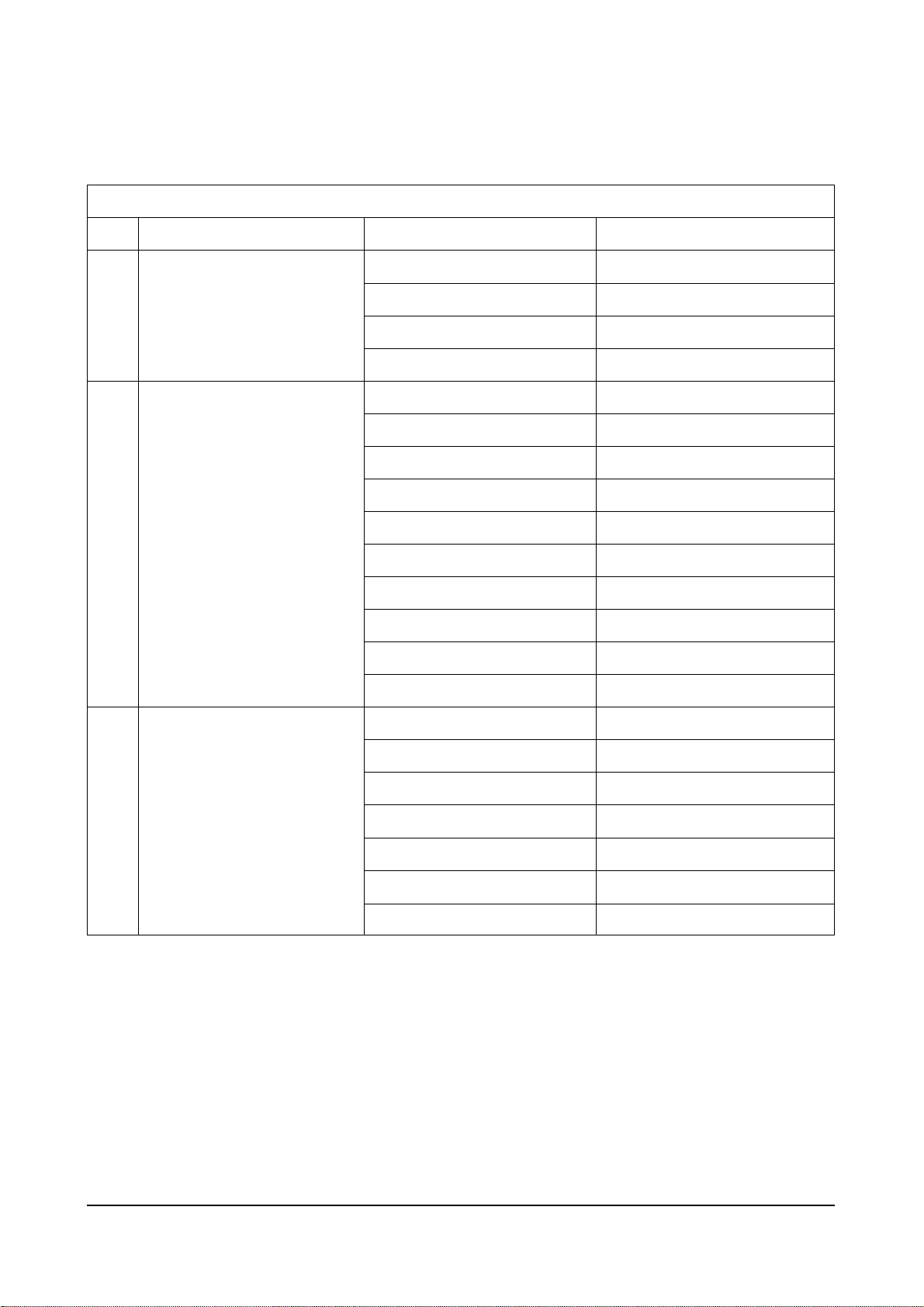
Block NameNo. IC Location IC Name
Table 2 - 3 IC Line - Up (Continued)
FORMAT-CONVERTER
PROSCAN
3D-PHONIC
IC01 FS310KBC
IC02 72V161621
IC03 Z9021106PSC
IC04 24C02
IC201 CIP3250A
IC202 VPC3215C
IC203 7705
IC204 SDS9280
ICP301 SDA9400
IC209 SDA9361
IC212 74F125
ICV02 CXA2011Q
ICY03 CXA1839Q
ICY17 74HCT221
ICD101 TL062CDT
ICD102 SAA7367
ICD103 TMS57052
ICD104 LC32464M
ICD105 Z9021106PSC
ICD106, ICD107 PCM1717E
ICD108,ICD109,ICD110,ICD111 TL062CDT
Reference Information
Samsung Electronics 2-5
1
2
3
4
5
6
7
8
9
10
IC665 TDA7265
IC904 KS24C04
ICS801 TNY253P
ICS802 PC123
IC601 TDA7429S
IC602 KA4558
IC905 PCF8574P
ICV01 TA8851BN
ICV02,ICV03 HCF4053BE
ICP01 SDA9488X
ICP02 4931
IC101 TDA9850
IC101 LA7565B
IC471 TL494CN
IC491 74HC123P
ICZ104,ICZ103 STK392-010
IC301 LA7845
IC801 STR-F6656
IC802 SVD001
IC804 SE110N
IC806 PS2561
IC501,IC531,IC561 TDA6111Q
IC01 UPD64082 GF
ICI02 CXA1686M
ICC03 CXD2043Q
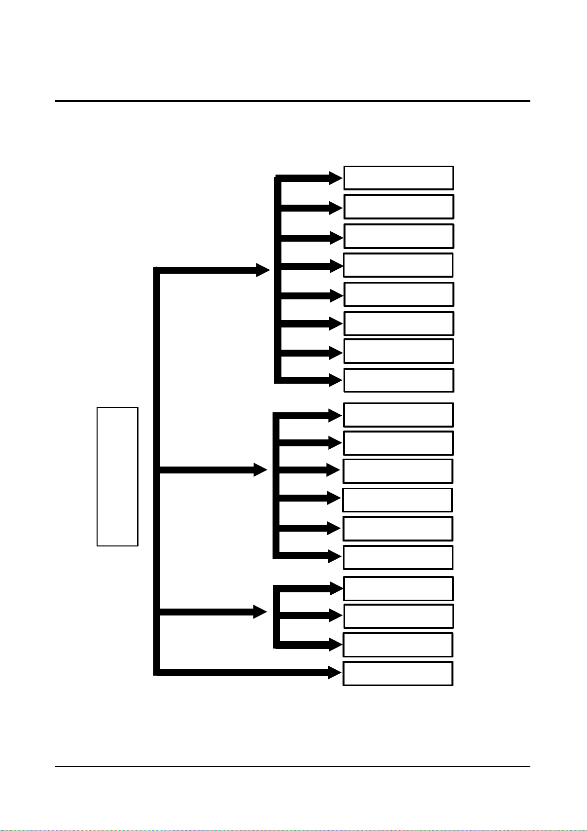
Block NameNo. IC Location IC Name
Table 2 - 3 IC Line - Up
2-2-2 Interlace
MAIN
TERMINAL BOARD
PIP
MTS MODULE
IF MODULE
HV MODULE
CONVERGENCE
SUB
CRT
2D-COMB

Reference Information
2-6 Samsung Electronics
11
Block NameNo. IC Location IC Name
Table 2 - 3 IC Line - Up (Continued)
CHROMA
IC201 CXA2095S
IC203 2210
IC204, IC206 BCF4053B
IC205 CXA1839Q
Reference Information
Samsung Electronics 2-7
2-3 MICOM IIC BUS LINE -UP
2-3-1 Progressive
XLS24C02
SLAVE ADDR.: A0h
UPD6488
SLAVE ADDR.: B8h
TDA9850
SLAVE ADDR.: B4h
Z
9
0
3
7
X
(
M
I
C
O
M
IIC 1 BUS
#30 : SDA 1
#31 : SCL 1
SDA9488
PCF8574P
SLAVE ADDR.: 40h
PCF8574P
SLAVE ADDR.: 42h
TECC1070PG30A
SLAVE ADDR.: C0h
TCPN9082PC27A
SLAVE ADDR.: C6h
SDA9400
CXA2011Q
SLAVE ADDR.: 84h
IIC 2 BUS
CIP3250A
#12 : SDA 2
#11 : SCL 2
(
SLAVE ADDR.: Dch
SDA9361
SLAVE ADDR.: 8ch
CXA1839Q
SLAVE ADDR.: 8Ah
SDA9280
SLAVE ADDR.: 2ch
TA8851AN
IIC 3 BUS
# 47 : SDA 3
# 48 : SCL 3
SLAVE ADDR.: 90h
TDA7429S
SLAVE ADDR.: 80h
PCF8574P
SLAVE ADDR.: 40h
SERIAL BUS
3D-PHONIC
MODULE
Reference Information
2-8 Samsung Electronics
2-3-2 Interlace
XLS24C02
SLAVE ADDR.: A0h
UPD6488
SLAVE ADDR.: B8h
TDA9850
SLAVE ADDR.: B4h
Z
9
0
3
5
X
(
M
I
C
O
M
IIC 1 BUS
SDA9488
#30 : SDA 1
#31 : SCL 1
IIC 2 BUS
#12 : SDA 2
#11 : SCL 2
PCF8574P
SLAVE ADDR.: 40h
PCF8574P
SLAVE ADDR.: 42h
TECC1070PG30A
SLAVE ADDR.: C0h
TCPN9082PC27A
SLAVE ADDR.: C6h
CXA2095
CXA1839Q
(
TA8851AN
IIC 3 BUS
# 47 : SDA 3
# 48 : SCL 3
SLAVE ADDR.: 90h
TDA7429S
SLAVE ADDR.: 80h
PCF8574P
SLAVE ADDR.: 40h
SERIAL BUS
3D-PHONIC
MODULE
Specifications
Samsung Electronics 3-1
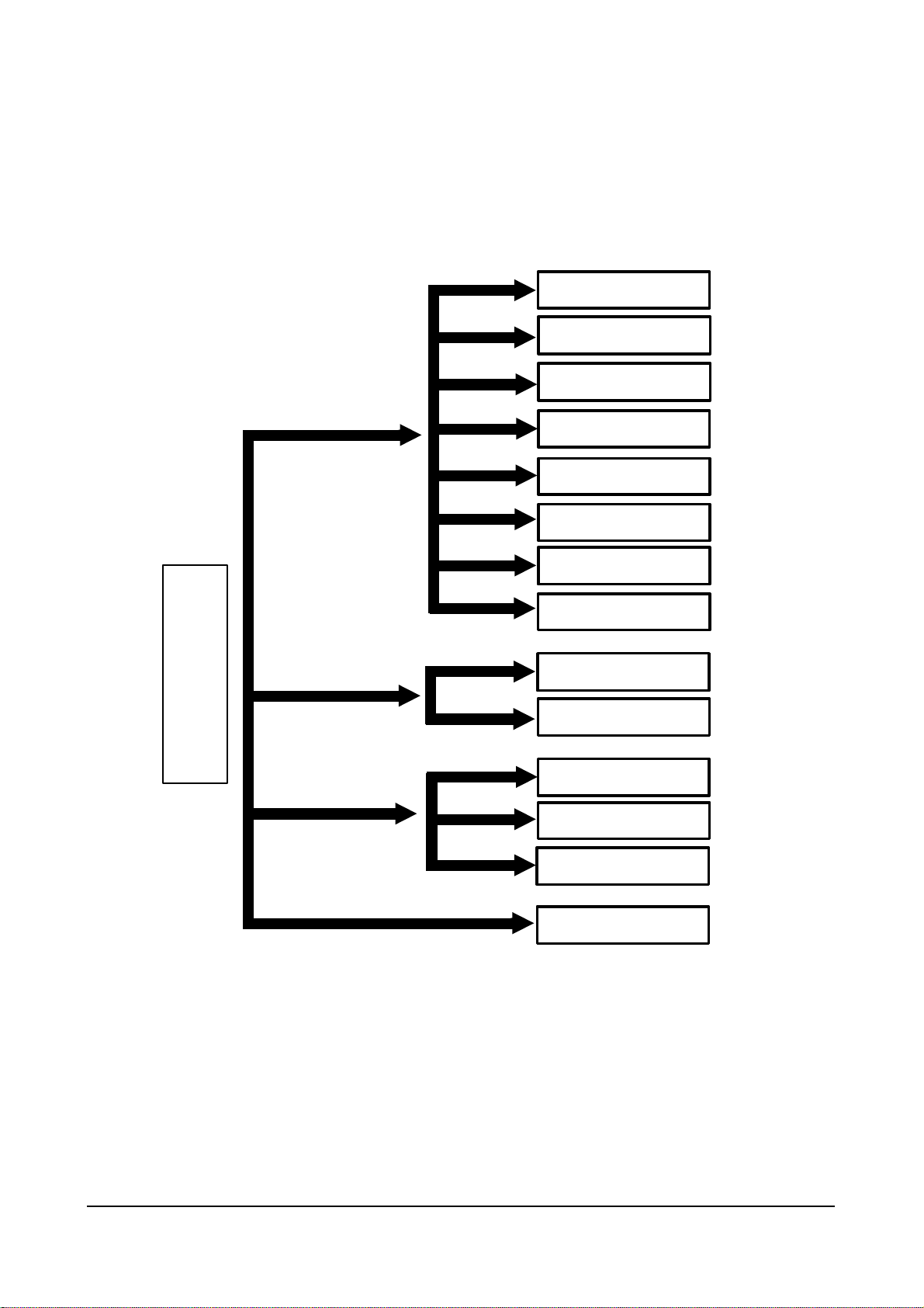
3. Specifications
Broadcasting System
Scanning System
Tuning Range
Antenna Impedance
Intermediate Frequency
Sound Output
Rated Voltage
W/B Coordinates
High Voltage
FUSE
Power Consumption
NTSC
Progressive Scanning
VHF : CH2 ~ CH13
UHF : CH14 ~ CH69
Cable : CH1, CH14 ~ 125
75 ohm Unbalanced
Video : 45.75 MHz
Sound : 42.25 MHz
Chrominance Subcarrier : 42.17 MHz
STD : 15W
FULL MAX : 20W
120V / 60 Hz
Hx : 292 Hy : 260 Y : 14.5
Lx : 293 Ly : 263 Y : 0.23
31KV
250V/6.3A
CODE NO : 3601-000300
285W

Alignment and Adjustments
Samsung Electronics 4-1
4. Alignment and Adjustments
4-1 When entering the service mode:
1. Turn on the TV, and then select “STANDARD”on the picture adjustment mode.
2. Turn off the TV (STAND-BY).
3. Enter the service mode by pressing the remote control keys in the following sequence :
MUTE 1→8→2→Power On
Note : If necessary, re-do steps 1~3.
Initial display when the service mode is switched.
SERVICE NORMAL 480P
GEOMETRICS
PICTURE
PICTURE2
SOUND
PIP
OPTION
READ
RESET
1. When a RF signal is received
SERVICE NORMAL 1080i
GEOMETRICS
PICTURE
PICTURE2
SOUND
PIP
OPTION
READ
RESET
2. When a DTV signal is received
Alignment and Adjustments
4-2 Samsung Electronics
MAIN MENU
ZOOM
COMPRESS
FREEZE
SET UP
RESET
EXIT
3. When the PC mode is switched
MAIN MENU MENU DISPLAY
CH UP/DOWN Select item by moving cursor
VOL UP/DOWN Decrease or increase the adjustment values
4. Service Mode Control Keys
Note : The PC mode can be switched to the service mode by pressing the
F.Mode Key (only on the factory remote control).
Alignment and Adjustments
Samsung Electronics 4-3
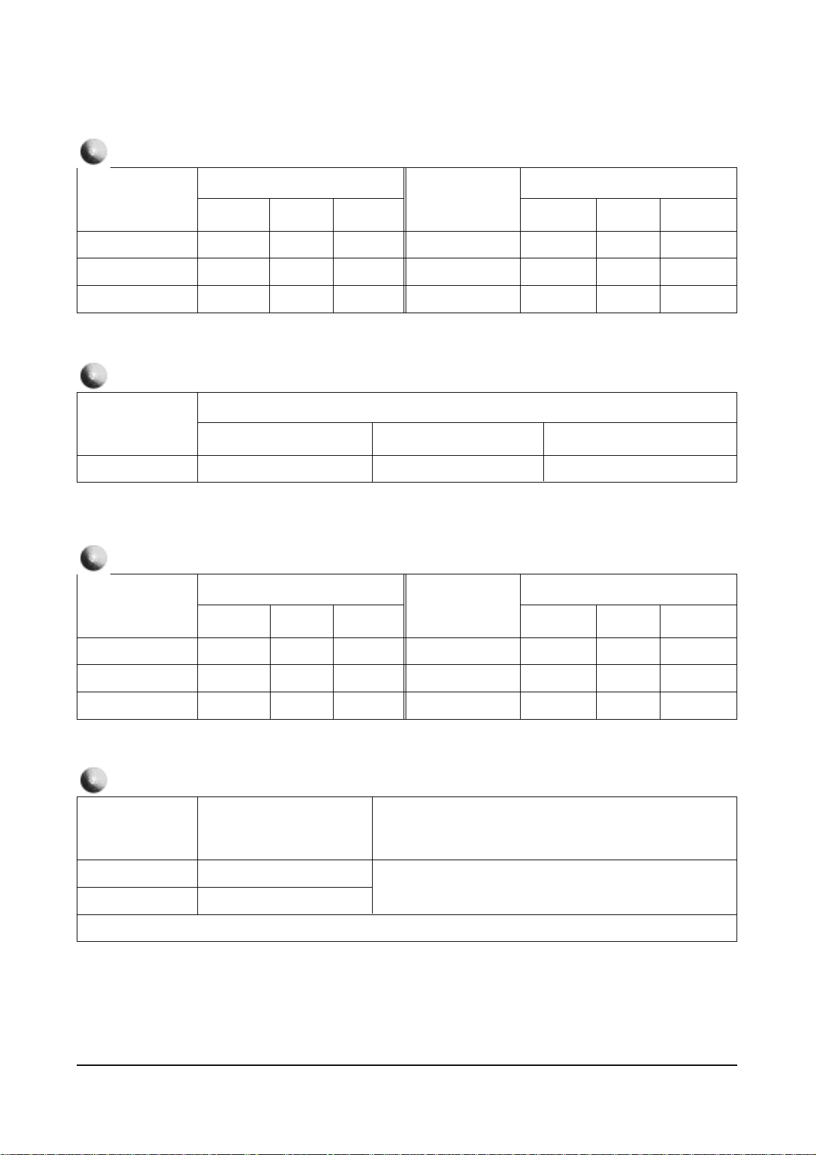
Item
TV/480P
Item
1080i
43”
53” 61”
VS
VA
VL
VSC
VE
HA
PPH
PA
UPC
LOC
132
122
114
104
0
80
100
96
128
128
132
122
114
104
0
80
100
96
128
128
114
88
114
104
0
80
100
96
128
128
HEH
HS
VAN
VBO
HSP
VS4
VA4
HS4
HA4
HP4
0
63
131
128
141
150
96
56
106
131
0
63
131
128
141
150
96
56
106
131
0
60
131
128
141
125
53
45
54
VS
VA
VL
VSC
VE
HA
PPH
PA
UPC
LOC
HEH
HS
VAN
VBO
HSP
VS4
VA4
HS4
HA4
HP4
53”
61”
Remark
128
75
114
104
0
114
100
96
128
128
0
65
131
128
139
150
96
56
106
131
91
96
62
125
53
45
54
GEOMETRIC
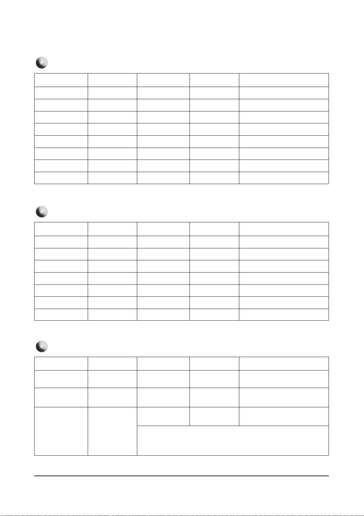
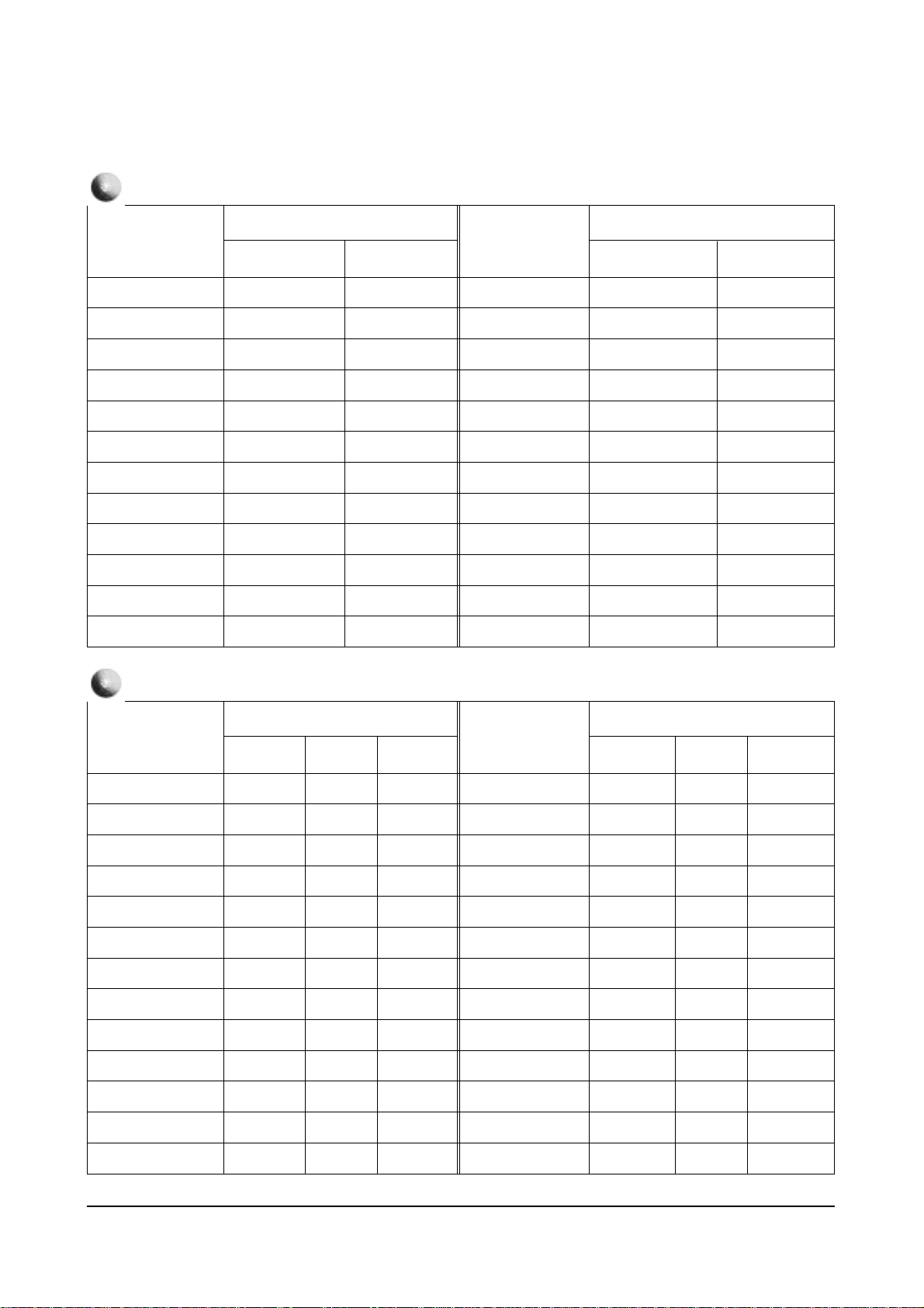
4-2 Facotry Data
4-2-1 Progressive
Alignment and Adjustments
4-4 Samsung Electronics
Model
Remark
OPTION
PCJ533RF
PCJ533R
PCJ534RF
PCK520R
PCJ614RF
PCK5315R
PCK6115R
Byte
Model
Byte
PCJ534R
HCJ552W
HCJ652W
BYTE 0 : 71
BYTE 1 : 54
BYTE 0 : 71
BYTE 1 : 50
BYTE 0 : 71
BYTE 1 : 44
BYTE 0 : 71
BYTE 1 : 40
BYTE 0 : 79
BYTE 1 : 41
BYTE 0 : 39
BYTE 1 : 41
Item
Remark
PICTURE
RDR
GDR
BDR
RCT
GCT
BCT
ABM
ATH
Picture
Item
Picture
20
20
20
31
31
31
1
1
RYR
RYB
GYR
GYB
GAM
HWD
HTM
HSE
2
13
12
9
12
2
1
0
Item
Remark
PICTURE 2
SBR
SCT
SCL
SHU
CTI
SSP
SFO
Picture
Item
Picture
31
7
12
8
1
2
2
POV
LTI
VML
VMD
DCT
DPC
3
2
2
3
3
1
Alignment and Adjustments
Samsung Electronics 4-5
Item
Initial Value
Item
Initial Value
43”
VS
VA
VCP
VLN
VSC
HS
HPC
HA
HPP
HAA
HAB
HUC
32
32
0
5
3
0
17
20
8
11
0
8
HLC
VAS
VSR
VUV
VLV
VJS
VZS
VRP
VBS
HBS
HLB
HRB
43”
Remark
8
40
25
0
0
0
0
3
3
0
15
15
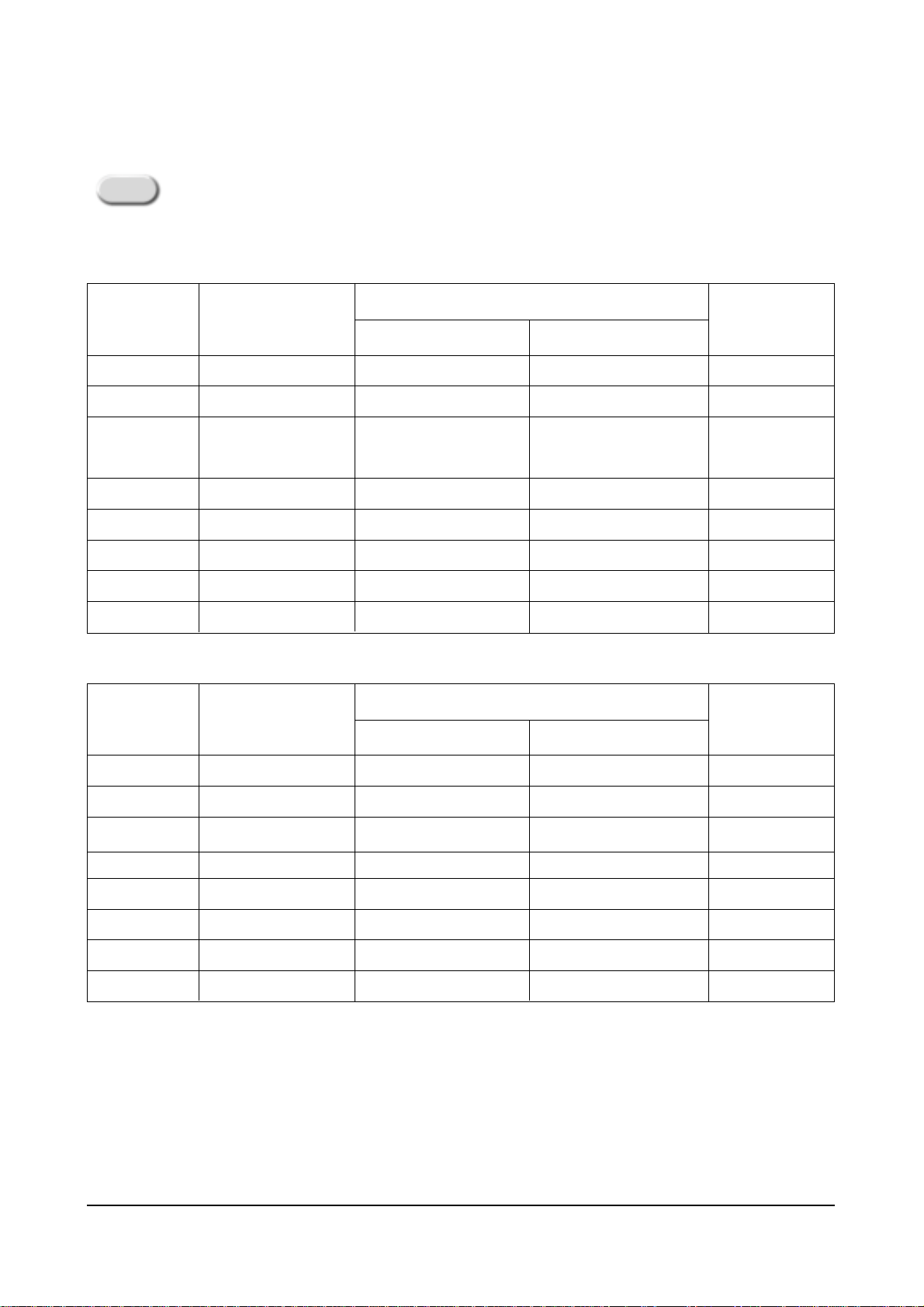
GEOMETRIC
4-2-2 Interlace
Remark
Variable
Variable
Variable
Variable
Item
Initial Value
Item
Initial Value
43”
DCT
DPI
AS
DCL
ABL
POV
SFO
TA
SCT
SBT
SCR
STT
GA
1
1
1
1
1
2
1
1
5
8
7
9
32
BA
GC
BC
GAM
AFC
TO
SSP
AMS
FHS
CFS
SC
LWC
COR
PICTURE
Remark
Variable
52”
43”
32
8
8
2
2
1
5
1
0
0
30
32
50
Remark
Variable
Variable
Variable
Variable
52”
32
8
8
2
2
1
5
1
0
0
30
32
50
Alignment and Adjustments
4-6 Samsung Electronics
Item
Initial Value
Item
Initial Value
43”
PIC
HUE
BRT
55
7
8
RYR
RYB
SHP
PICTURE 2
REMARK
52”
55
7
8
43”
15
15
0
REMARK
52”
15
15
0
Item
Initial Value
43”
SEPERATE
15
SOUND
Remark
52”
16
Item
Initial Value
Item
Initial Value
43”
Contrast
HUE
POS-HOR-L
5
3
32
POS-HOR-R
POS-VER-U
POS-VER-D
PIP
REMARK
Variable
52”
5
3
32
43”
29
21
21
REMARK
52”
29
21
21
Item
Initial Value
Byte0
Byte1
91
01
OPTION
Remark
Dissimilar initial values by model and function
Aging Off
Alignment and Adjustments
Samsung Electronics 4-7
Byte : 00
Name
D7
D6
D5
D4
D3
D2
D1
D0
SharpCenter50En
CXA1839(DVD)
V-Chip
AFN
Auto Power On
Note 1
Remark
Current Set Setting
Option adjustment is done in the service mode
0
X
Sharpness, Color, Tint
adjustment available
in the DVD Menu
X
X
X
1
Operate
Sharpness, Color, Tint
not adjustable
in the DVD Menu
Operate
Operate
Operate
Function
SZM-386U OPTION TABLE
Byte : 01
Name
D7
D6
D5
D4
D3
D2
D1
D0
3D Comb-filter
All Mighty Conv.
Remark
0
UPD6488
X
1
UPD64082
Operate
Function
Alignment and Adjustments
4-8 Samsung Electronics
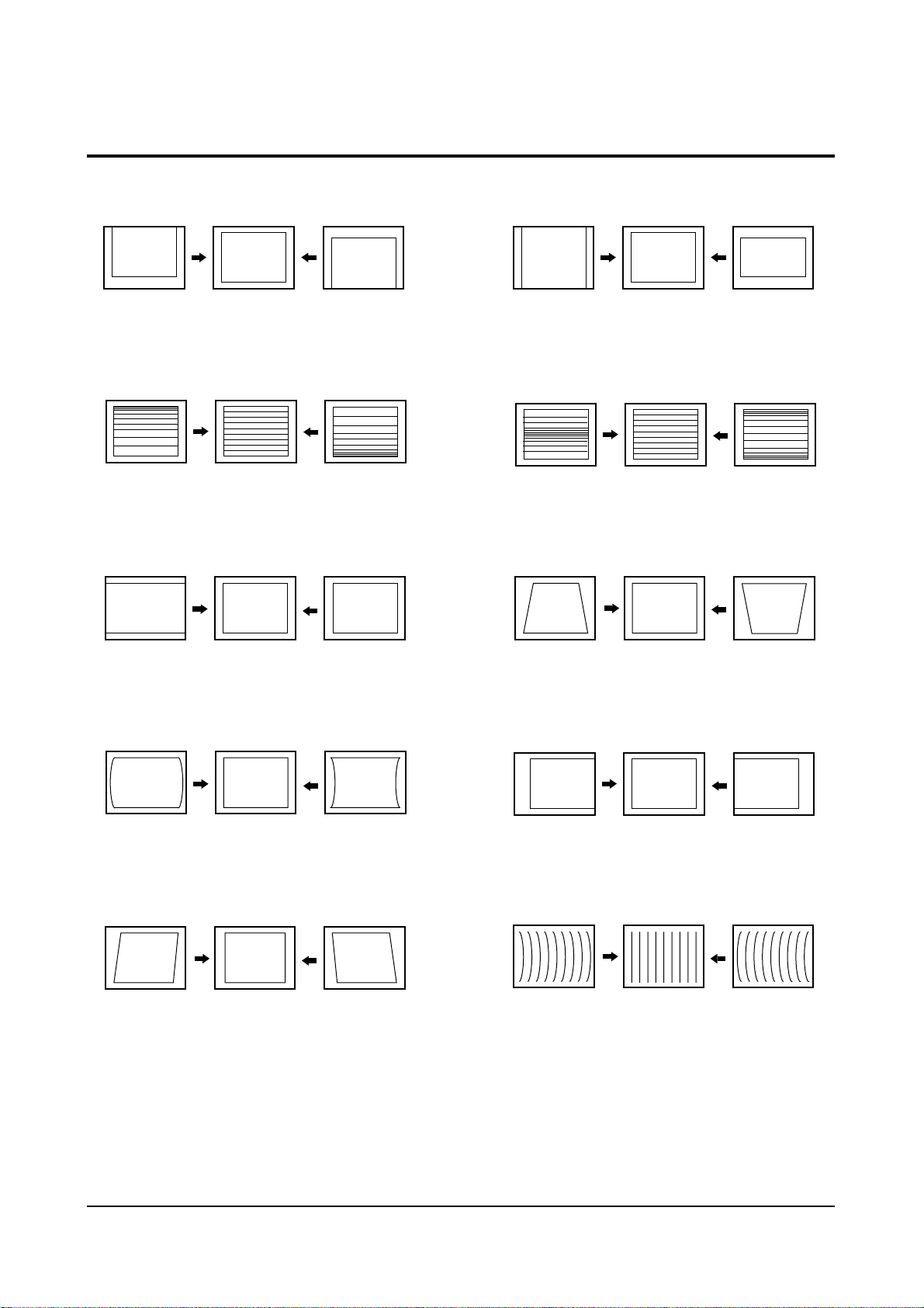
4-2 Screen Change (When adjusting I2C Bus Geometric items)
1 V SHIFT
2 V LINEARITY
3 H SIZE
6 V SIZE
7 V - S - CORRECTION
8
PIN PHASE
4
PIN AMP
5 V ANGLE
9 H SHIFT
10 V BOW
Alignment and Adjustments
Samsung Electronics 4-9
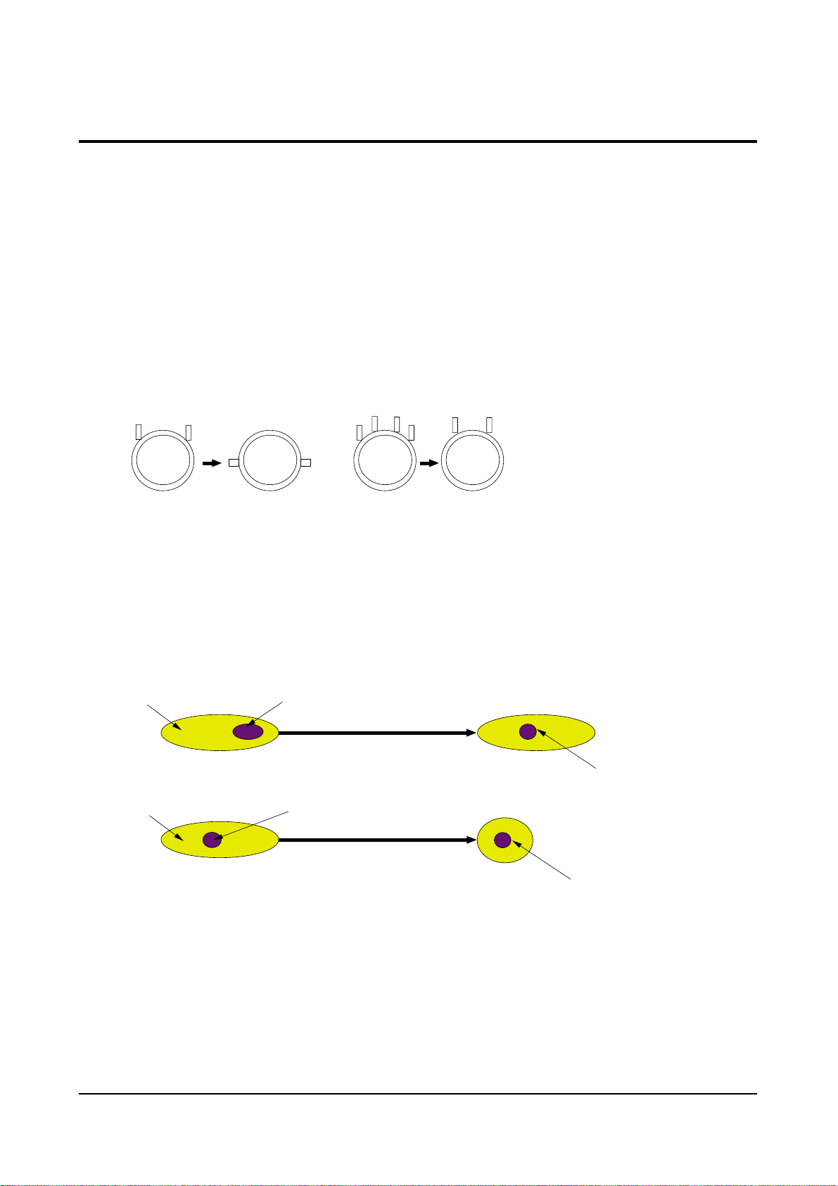
4-3 Beam Alignment
PRECAUTION
1. Input a crosshatch and dot pattern.
2. Select the “STANDARD” video mode.
3. Warm up the TV for at least 10 minutes.
4. Connect an audio oscillator to the pin jig between GT401~GT402 (located on the deflection
PCB) and GND.
5. Determine the ZERO-magnet area (using the beam-alignment CY)
6. Check the squarewave at the point where the focus is misaligned (Use an audio oscillator).
ADJUSTMENT
1. Cover the Red and Blue lenses.
2. Adjust the Green lens as shown in the figures below
3. Adjust the G-Focus until any light around the core disappears.
4. Cover the Green and Blue lenses.
5. Adjust the Red lens using the same method as with the Green lens.
6. Note: The Blue lens is not adjusted because its focus varies little (VM-coil is installed).
7. After the adjustments are completed, disconnect the jig pin connector.
(Creation of CPM Zero Magnet)
(Creation of the 2-pole/4-pole zero magnets)
G-FOCUS
(Varying G-Focus Pack)
G-FOCUS
(When VM 2-Pole Adjustment is completed)
CORE
CORE
Varying the 2-pole of VM
Varying the 4-pole of VM
(Positioning the Core in the Center)
(Adjust until the light around
the core becomes a circle)

Alignment and Adjustments
4-10 Samsung Electronics
4-4 Other Adjustments
4-4-1 Screen Adjustment
1. Warm up the TV for at least 30 minutes.
2. Turn to the Video Mode (No Signal) using a
remote-control.
3. Connect an oscilloscope to RK,GK,BK.
4. Adjust the VR (VR501, VR531, VR561) screen
so that RK, GK, BK pulse is 20Vp-p each.
(Turn the R,G,B VR screen fully
counterclockwise in the area of each flyback
line.)
4-4-2 White Balance Adjustment
1. Select the “STANDARD” video mode.
2. Input 100% white pattern.
3. In the stand-by mode, press the remote-control
keys in the following sequence:
Mute → 1 → 8 → 2 → Power ON
4. Warm up the TV for at least 30 minutes.
5. Input a 10-step signal.
6. R-cut off, B-cut off, and G-cut off by pressing
the Volume +/- keys.
7. Adjust the low light with viewing the dark
side of the screen.
8. Select R-drive, G-drive, and B-drive by
pressing the Volume +/- keys.
9. Adjust the high light with viewing the light
side of the screen.
10. If necessary, redo adjustments 6~9.
11. Press the Menu key to exit.
4-4-3 Sub-Brightness Adjustment
1. Input a sub-brightness adjustment signal.
(TOSHIBA PATTERN)
2. In the stand-by mode, press the remote-control
keys in the following sequence :
Mute - 1 - 8 - 2 - Power ON
3. Select SBT by pressing the Volume +/- keys.
4. Adjust so that the 7th step on the right side of
the screen is not seen (Use the Volume +/keys).
5. Press the Menu key to exit.
4-4-4 High Voltage (31KV) Check
PRECAUTION
1. Input a lion head pattern.
2. Select “STANDARD” video mode.
3. Warm up the TV for at least 10 minutes.
4. Use a 1000:1 probe.
ADJUSTMENT
1. Connect the (+) terminal of the 1000:1 probe to
the high voltage distributor and the (-)
terminal to GND (located on the deflection
board).
2. Adjust VR471 (located on the deflection board)
so that the digital meter indicates
DC 31V ± 0.1V.
Alignment and Adjustments
Samsung Electronics 4-11
4-4-5 F.S. (Fail Safe) Circuit Check
Note : The F.S. Circuit check must be performed
after servicing.
1. Turn on the TV.
2. Select the “STANDARD” video mode.
3. Short GT18, GT17 (located on the
Convergence PCB). Then, both sound and
picture disappear. (Note: Even if the shorted
terminals are removed, both sound and
picture do not appear. This proves the F.S.
circuit is working. )
4. To restore both sound and picture, turn off the
TV and reset it after about 30 seconds.
4-4-6 Static Focus Adjustment
PRECAUTION
1. Select the “STANDARD” video mode.
2. Input a crosshatch pattern.
3. Cover the lenses that are not being adjusted.
4. Connect a convergence jig and read data.
5. Adjust the lens for best focus.
(See Fig, 4-1, next page)
STATIC FOCUS (CONTINUED)
Vary the focus pack VR (Red, Blue) on the
front cabinet. Adjust the TV for best possible
focus around the center of the crosshatch
pattern, without losing overall screen balance.
Figure Crosshatch Pattern
Examine these points together.
4-4-7 Lens Focus Adjustment
PRECAUTIONS
1. Do this adjustment after the static focus
adjustment and the tilt adjustment.
2. Select the “STANDARD” video mode.
(Contrast:64, Brightness:32)
3. Input a crosshatch pattern.
ADJUSTMENT
1. Loosen the lens screws.
2. Cover the two lenses that are not being
adjusted.
3. Adjust the lens, observing the color aberration
vertically and horizontally within 3 blocks of
the center of the crosshatch pattern.
4. When the lens is turned clockwise, the color
aberration will change as follows:
Lens
Color Aberration Change
R Orange - Crimson
G Blue - Red
B Purple - Green
5. Green lens adjustment:
Set the lens at the point where Blue just
changes to Red. If the color aberration is
irregular throughout the picture screen, adjust
the lens to show Red color aberration
(approximately 1~3 mm area) within a 3-block
grid around the horizontal center-line. If the
color aberration is irregular, adjust the lens as
shown in the diagram below. (Accurate
alignment of Green is important for overall
color quality.)
6. Red lens adjustment
Set the Red lens at the point where Orange
becomes Crimson.
7. Blue lens adjustment
Set the Blue lens at the point where Purple
becomes Green.
P
L1
L2
RED ABERRATION
BLUE ABERRATION
L1, L2 < P
_
Fig. 4-1 Crosshatch Pattern.
Fig. 4-2 Color Aberration
Examine these points together

Alignment and Adjustments
4-12 Samsung Electronics
4-4-8 Horizontal Dynamic Focus Adjustment
PRECAUTION
1. Input a crosshatch pattern.
2. Select the “STANDARD” video mode.
3. Warm up the set for at least 10 minutes.
ADJUSTMENT
1. Cover the Red and Blue lenses.
2. Adjust VR491 (located on the convergence
PCB, H-Parabola).
3. Balance the left and right sides of the dynamic
focus lines.
Alignment and Adjustments
Samsung Electronics 4-13
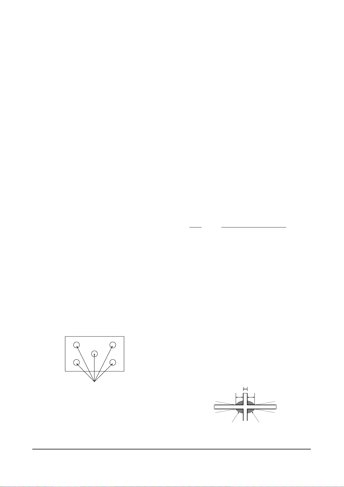
4-5 Screen-Jig
4-5-1 43J5P
4-5-2 43J5P DTV Mode
Alignment and Adjustments
4-14 Samsung Electronics
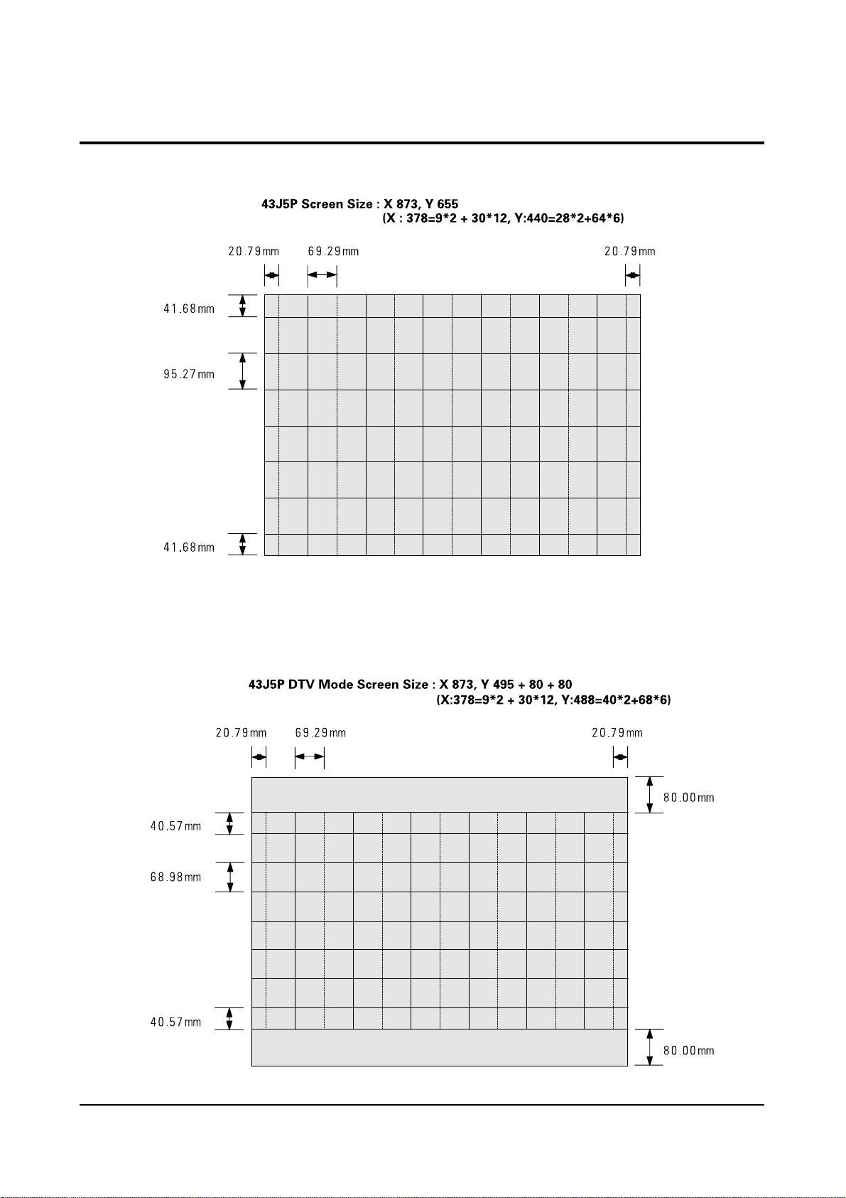
4-5-3 53J5P
4-5-4 53J5P DTV Mode
Alignment and Adjustments
Samsung Electronics 4-15
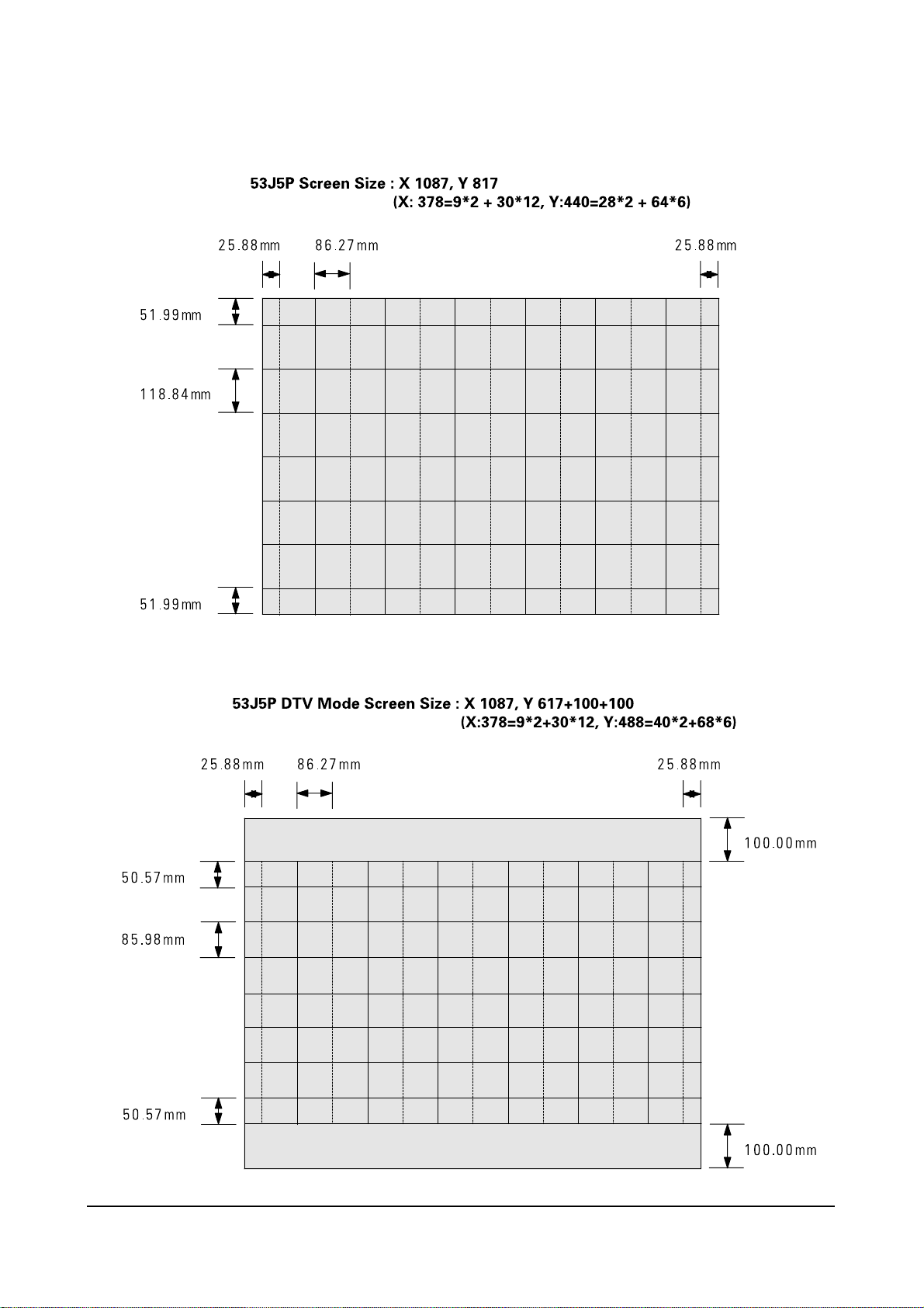
4-5-5 61J5P
4-5-6 61J5P DTV
 Loading...