


PROJECTION TV RECEIVER
Chassis : P51A
Model: PCJ522RX/XAA
PCJ612RX/XAA
PCJ522RX/XAC
PCJ612RX/XAC
PROJECTION TV RECEIVER C O N T E N T S
Precautions
1.
Reference Information
2.
Specifications
3.
Alignment and Adjustments
4.
Troubleshooting
5.
Exploded View and Parts List
6.
Electrical Parts List
7.
Block Diagrams
8.
Wiring Diagram
9.
Schematic Diagrams
10.

ELECTRONICS
© Samsung Electronics Co., Ltd. OCT. 1999
Printed in Korea
3P51A-5201
1. Precautions
1-1 Safety Precautions
1. Be sure that all of the built-in protective
devices are replaced. Restore any missing
protective shields.
2. When reinstalling the chassis and its
assemblies, be sure to restore all protective
devices, including: nonmetallic control knobs
and compartment covers.
3. Make sure that there are no cabinet openings
through which people—particularly
children—might insert fingers and contact
dangerous voltages. Such openings include
the spacing between the picture tube and the
cabinet mask, excessively wide cabinet
ventilation slots, and improperly fitted back
covers.
If the measured resistance is less than 1.0
megohm or greater than 5.2 megohms, an
abnormality exists that must be corrected
before the unit is returned to the customer.
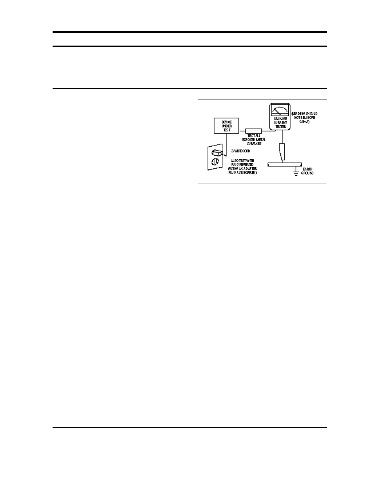
4. Leakage Current Hot Check (Figure 1-1):
Warning: Do not use an isolation
transformer during this test. Use a leakagecurrent tester or a metering system that
complies with American National Standards
Institute (ANIS C101.1, Leakage Current for
Appliances), and Underwriters Laboratories
(UL Publication UL1410, 59.7).
5. With the unit completely reassembled, plug
the AC line cord directly into the power
outlet. With the unit’s AC switch first in the
ON position and then OFF, measure the
current between a known earth ground (metal
water pipe, conduit, etc.) and all exposed
metal parts, including: antennas, handle
brackets, metal cabinets, screwheads and
control shafts. The current measured should
not exceed 0.5 milliamp. Reverse the powerplug prongs in the AC outlet and repeat the
test.
Fig. 1-1 AC Leakage Test
6. Antenna Cold Check:
With the unit’s AC plug disconnected from the
AC source, connect an electrical jumper across
the two AC prongs. Connect one lead of the
ohmmeter to an AC prong. Connect the other
lead to the coaxial connector.
7. X-ray Limits:
The picture tube is especially designed to prohibit X-ray emissions. To ensure continued
X-ray protection, replace the picture tube only
with one that is the same type as the original.
Carefully reinstall the picture tube shields and
mounting hardware; these also provide X-ray
protection.
8. High Voltage Limits:
High voltage must be measured each time servicing is done on the B+, horizontal deflection
or high voltage circuits. Correct operation of
the X-ray protection circuits must be
reconfirmed whenever they are serviced.
(X-ray protection circuits also may be called
“horizontal disable” or “hold-down”.)
Heed the high voltage limits. These include
the X–ray Protection Specifications Label, and
the Product Safety and X-ray Warning Note on
the service data schematic.
Precautions
Samsung Electronics 1-1
Follow these safety, servicing and ESD precautions to prevent damage and protect against potential
hazards such as electrical shock and X-rays.

1-1 Safety Precautions (Continued)
9. High voltage is maintained within specified
limits by close-tolerance, safety-related
components and adjustments. If the high
voltage exceeds the specified limits, check
each of the special components.
10. Design Alteration Warning:
Never alter or add to the mechanical or
electrical design of this unit. Example: Do not
add auxiliary audio or video connectors. Such
alterations might create a safety hazard. Also,
any design changes or additions will void the
manufacturer’s warranty.
11. Hot Chassis Warning:
Some TV receiver chassis are electrically
connected directly to one conductor of the AC
power cord. If an isolation transformer is not
used, these units may be safely serviced only
if the AC power plug is inserted so that the
chassis is connected to the ground side of the
AC source.
To confirm that the AC power plug is inserted
correctly, do the following: Using an AC
voltmeter, measure the voltage between the
chassis and a known earth ground. If the
reading is greater than 1.0V, remove the AC
power plug, reverse its polarity and reinsert.
Re-measure the voltage between the chassis
and ground.
12. Some TV chassis are designed to operate with
85 volts AC between chassis and ground,
regardless of the AC plug polarity. These units
can be safely serviced only if an isolation
transformer inserted between the receiver and
the power source.
13. Some TV chassis have a secondary ground
system in addition to the main chassis ground.
This secondary ground system is not
isolated from the AC power line. The two
ground systems are electrically separated by
insulating material that must not be defeated
or altered.
14. Components, parts and wiring that appear to
have overheated or that are otherwise
damaged should be replaced with parts that
meet the original specifications. Always
determine the cause of damage or overheating, and correct any potential hazards.
15. Observe the original lead dress, especially
near the following areas: Antenna wiring,
sharp edges, and especially the AC and high
voltage power supplies. Always inspect for
pinched, out-of-place, or frayed wiring. Do
not change the spacing between components
and the printed circuit board. Check the AC
power cord for damage. Make sure that leads
and components do not touch thermally hot
parts.
16. Picture Tube Implosion Warning:
The picture tube in this receiver employs
“integral implosion” protection. To ensure
continued implosion protection, make sure
that the replacement picture tube is the same
as the original.
17. Do not remove, install or handle the picture
tube without first putting on shatterproof
goggles equipped with side shields. Never
handle the picture tube by its neck. Some
“in-line” picture tubes are equipped with a
permanently attached deflection yoke; do not
try to remove such “permanently attached”
yokes from the picture tube.
18. Product Safety Notice:
Some electrical and mechanical parts have
special safety-related characteristics which
might not be obvious from visual inspection.
These safety features and the protection they
give might be lost if the replacement component differs from the original—even if the
replacement is rated for higher voltage,
wattage, etc.
Components that are critical for safety are
indicated in the circuit diagram by shading,
( ) or ( ).
Use replacement components that have the
same ratings, especially for flame resistance
and dielectric strength specifications.
Areplacement part that does not have the
same safety characteristics as the original
might create shock, fire or other hazards.
Precautions
1-2 Samsung Electronics

1-2 Servicing Precautions
1. Servicing precautions are printed on the
cabinet. Follow them.
2. Always unplug the unit’s AC power cord from
the AC power source before attempting to: (a)
Remove or reinstall any component or
assembly, (b) Disconnect an electrical plug or
connector, (c) Connect a test component in
parallel with an electrolytic capacitor.
3. Some components are raised above the printed
circuit board for safety. An insulation tube or
tape is sometimes used. The internal wiring is
sometimes clamped to prevent contact with
thermally hot components. Reinstall all such
elements to their original position.
4. After servicing, always check that the screws,
components and wiring have been correctly
reinstalled. Make sure that the portion around
the serviced part has not been damaged.
5. Check the insulation between the blades of the
AC plug and accessible conductive parts
(examples: metal panels, input terminals and
earphone jacks).
6. Insulation Checking Procedure: Disconnect the
power cord from the AC source and turn the
power switch ON. Connect an insulation
resistance meter (500V) to the blades of the AC
plug.
The insulation resistance between each blade
of the AC plug and accessible conductive parts
(see above) should be greater than 1 megohm.
7. Never defeat any of the B+ voltage interlocks.
Do not apply AC power to the unit (or any of
its assemblies) unless all solid-state heat sinks
are correctly installed.
8. Always connect a test instrument’s ground
lead to the instrument chassis ground before
connecting the positive lead; always remove
the instrument’s ground lead last.
9. When some parts inside the optical engine
(except lamp) are damaged, replace the whole
optical engine.
Precautions
Samsung Electronics 1-3
Warning 1 : First read the “Safety Precautions” section of this manual. If some unforeseen circumstance creates a
conflict between the servicing and safety precautions, always follow the safety precautions.
Warning 2 : An electrolytic capacitor installed with the wrong polarity might explode.

1-3 Precautions for Electrostatically Sensitive Devices (ESDs)
1. Some semiconductor (“solid state”) devices
are easily damaged by static electricity. Such
components are called Electrostatically
Sensitive Devices (ESDs); examples include
integrated circuits and some field-effect
transistors. The following techniques will
reduce the occurrence of component damage
caused by static electricity.
2. Immediately before handling any semicon
ductor components or assemblies, drain the
electrostatic charge from your body by
touching a known earth ground. Alternatively,
wear a discharging wrist-strap device. (Be
sure to remove it prior to applying power—
this is an electric shock precaution.)
3. After removing an ESD-equipped assembly,
place it on a conductive surface such as
aluminum foil to prevent accumulation of
electrostatic charge.
4. Do not use freon-propelled chemicals. These
can generate electrical charges that damage
ESDs.
5. Use only a grounded-tip soldering iron when
soldering or unsoldering ESDs.
6. Use only an anti-static solder removal device.
Many solder removal devices are not rated as
“anti-static”; these can accumulate sufficient
electrical charge to damage ESDs.
7. Do not remove a replacement ESD from its
protective package until you are ready to
install it. Most replacement ESDs are
packaged with leads that are electrically
shorted together by conductive foam,
aluminum foil or other conductive materials.
8. Immediately before removing the protective
material from the leads of a replacement ESD,
touch the protective material to the chassis or
circuit assembly into which the device will be
installed.
9. Minimize body motions when handling
unpackaged replacement ESDs. Motions such
as brushing clothes together, or lifting a foot
from a carpeted floor can generate enough
static electricity to damage an ESD.
Precautions
1-4 Samsung Electronics

Reference Information
Samsung Electronics 2-1
2. Reference Information
2-1 Tables of Abbreviations and Acronyms
A
Ah
Å
dB
dBm
°C
°F
°K
F
G
GHz
g
H
Hz
h
ips
kWh
kg
kHz
kΩ
km
km/h
kV
kVA
kW
I
MHz
Ampere
Ampere-hour
Angstrom
Decibel
Decibel Referenced to One
Milliwatt
Degree Celsius
Degree Fahrenheit
degree Kelvin
Farad
Gauss
Gigahertz
Gram
Henry
Hertz
Hour
Inches Per Second
Kilowatt-hour
Kilogram
Kilohertz
Kilohm
Kilometer
Kilometer Per Hour
Kilovolt
Kilovolt-ampere
Kilowatt
Liter
Megahertz
MV
MW
MΩ
m
µA
µF
µH
µm
µs
µW
mA
mg
mH
mI
mm
ms
mV
nF
Ω
pF
Ib
rpm
rps
s
V
VA
W
Wh
Megavolt
Megawatt
Megohm
Meter
Microampere
Microfarad
Microhenry
Micrometer
Microsecond
Microwatt
Milliampere
Milligram
Millihenry
Milliliter
Millimeter
Millisecond
Millivolt
Nanofarad
Ohm
Picofarad
Pound
Revolutions Per Minute
Revolutions Per Second
Second (Time)
Volt
Volt-ampere
Watt
Watt-hour
Table 2-1 Abbreviations

Reference Information
2-2 Samsung Electronics
Table 2-2 Table of Acronyms
ABL
AC
ACC
AF
AFC
AFT
AGC
AM
ANSI
APC
APC
A/V
AVC
BAL
BPF
B-Y
CATV
CB
CCD
CCTV
Ch
CRT
CW
DC
DVM
EIA
ESD
ESD
FBP
FBT
FF
FM
FS
GND
G-Y
H
HF
HI-FI
IC
IC
IF
Automatic Brightness Limiter
Alternating Current
Automatic Chroma Control
Audio Frequency
Automatic Frequency Control
Automatic Fine Tuning
Automatic Gain Control
Amplitude Modulation
American National Standards Institute
Automatic Phase Control
Automatic Picture Control
Audio-Video
Automatic Volume Control
Balance
Bandpass Filter
Blue-Y
Community Antenna Television (Cable TV)
Citizens Band
Charge Coupled Device
Closed Circuit Television
Channel
Cathode Ray Tube
Continuous Wave
Direct Current
Digital Volt Meter
Electronics Industries Association
Electrostatic Discharge
Electrostatically Sensitive Device
Feedback Pulse
Flyback Transformer
Flip-Flop
Frequency Modulation
Fail Safe
Ground
Green-Y
High
High-Frequency
High Fidelity
Inductance-Capacitance
Integrated Circuit
Intermediate Frequency
I/O
L
L
LED
LF
MOSFET
MTS
NAB
NEC
NTSC
OSD
PCB
PLL
PWM
QIF
R
RC
RF
R-Y
SAP
SAW
SIF
SMPS
S/N
SW
TP
TTL
TV
UHF
UL
UV
VCD
VCO
VCXO
VHF
VIF
VR
VTR
VTVM
TR
Input/output
Left
Low
Light Emitting Diode
Low Frequency
Metal-Oxide-Semiconductor-Field-Effect-Tr
Multi-channel Television Sound
National Association of Broadcasters
National Electric Code
National Television Systems Committee
On Screen Display
Printed Circuit Board
Phase-Locked Loop
Pulse Width Modulation
Quadrature Intermediate Frequency
Right
Resistor & Capacitor
Radio Frequency
Red-Y
Second Audio Program
Surface Acoustic Wave(Filter)
Sound Intermediate Frequency
Switching Mode Power Supply
Signal/Noise
Switch
Test Point
Transistor Transistor Logic
Television
Ultra High Frequency
Underwriters Laboratories
Ultraviolet
Variable-Capacitance Diode
Voltage Controlled Oscillator
Voltage Controlled Crystal Oscillator
Very High Frequency
Video Intermediate Frequency
Variable Resistor
Video Tape Recorder
Vacuum Tube Voltmeter
Transistor

IC665 TDA7265
IC904 KS24C04
ICS801 TNY253P
ICS802 PC123
IC601 TDA7429S
IC602 KA4558
IC905 PCF8574P
ICV01 TA8851BN
ICV02,ICV03 HCF4053BE
ICP01 TDA8601
ICP02 TDA9160A
ICP03 SDA9288X
IC101 TDA9850
IC101 LA7565B
IC471 TL494CN
IC491 74HC123P
ICZ104,ICZ103 STK392-010
IC301 LA7845
IC801 STR-F6656
IC802 SVD001
IC804 SE110N
IC806 PS2561
IC501,IC531,IC561 TDA6111Q
IC01 UPD6488
ICI02 CXA1686M
ICC03 CXD2043Q
1
2
3
4
5
6
7
8
9
10
Block NameNo. IC Location IC Name
Table 2 - 3 IC Line - Up
Reference Information
Samsung Electronics 2-3
2-2 IC Line Up
MAIN
TERMINAL BOARD
PIP
MTS MODULE
IF MODULE
HV MODULE
CONVERGENCE
SUB
CRT
2D-COMB
Reference Information
2-4 Samsung Electronics
11
Block NameNo. IC Location IC Name
Table 2 - 3 IC Line - Up (Continued)
CHROMA
IC201 CXA2095S
IC202 TDA9177
IC203 MC14577BP
IC204, IC205 BCF4053B
Reference Information
Samsung Electronics 2-5
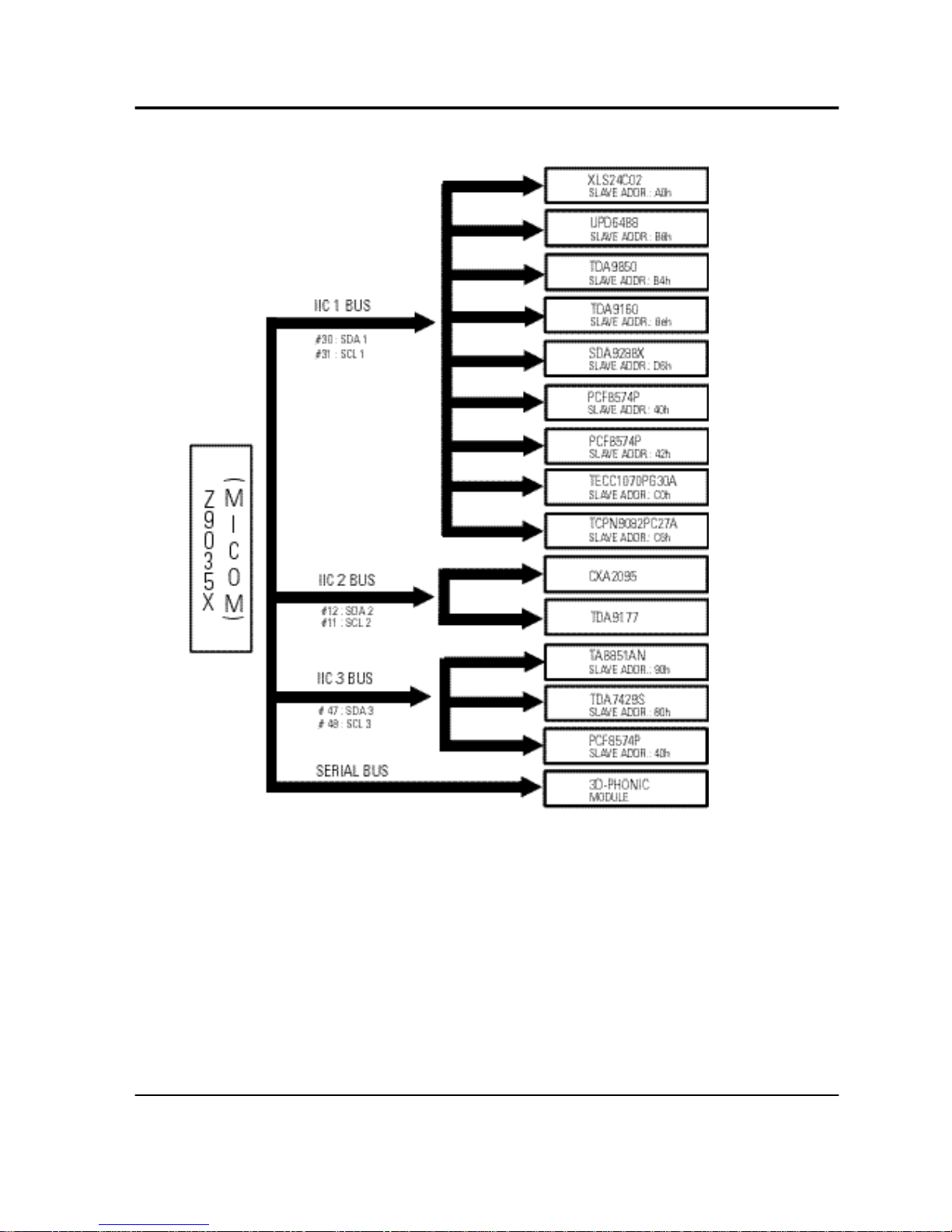
2-3 MICOM IIC BUS LINE -UP

2-6 Samsung Electronics
MEMO

Specifications
Samsung Electronics 3-1
3. Specifications
Broadcasting System
Scanning System
Tuning Range
Antenna Impedance
Intermediate Frequency
Sound Output
Rated Voltage
W/B Coordinates
High Voltage
FUSE
Power Consumption
NTSC
Interlace Scanning
VHF : CH2 ~ CH13
UHF : CH14 ~ CH69
Cable : CH1, CH14 ~ 125
75 ohm Unbalanced
Video : 45.75 MHz
Sound : 42.25 MHz
Chrominance Subcarrier : 42.17 MHz
STD : 15W
FULL MAX : 20 W
120V / 60 Hz
Hx : 292 ± 3 Hy : 270 ± 3 Y : 3.0 ± 0.2
Lx : 278 ± 5 Ly : 246 ± 5 Y : 0.13 ± 0.02
29 KV
250V/6.3A
CODE NO : 3601-000300
230W

3-2 Samsung Electronics
MEMO

Alignment and Adjustments
4.Alignment and Adjustments
4-1 When entering the service mode:
1. Turn on the TV, and then select “STANDARD”on the picture adjustment mode.
2. Turn off the TV (STAND-BY).
3. Enter the service mode by pressing the remote control keys in the following sequence :
MUTE →1→8→2→Power On
Note : If necessary, re-do steps 1~3.
Initial display when the service mode is switched.
FACTORY
GEOMETRIC
PICTURE
SOUND
PIP
OPTION
READ
RESET
1. When a RF signal is received
MAIN MENU MENU DISPLAY
CH UP/DOWN Select item by moving cursor
VOL UP/DOWN Decrease or increase the adjustment values
2. Service Mode Control Keys
Samsung Electronics 4-1
Alignment and Adjustments
4-2 Samsung Electronics
GEOMETRIC
VS 32 V-SHIFT HLC 8 PIN-LO-CORR
VA 32 V-SIZE VAS 40 V-ASPECT-SIZE
VCP 0 V-COMP VSR 25 V-SCROLL
VLN 5 V-LIN VUV 0 V-UP-LIN
VSC 3 V-S-CORR VLV 0 V-LO-LIN
HS 0 H-SHIFT VJS 0 V-JUMP-SW
HPC 17 PIN-AMP VZS 0 V-ZOOM-SW
HA 20 H-SIZE VRP 3 VBLKW
HPP 8 PIN-PHASE VBS 3 V-BLK-SW
HAA 7 V-ANGLE HBS 0 H-BLK-SW
HAB 5 V-BOW HLB 15 H-LEFT-BLK
HUC 8 PIN-UP-CORR HRB 15 H-RIGHT-BLK
PICTURE
DCT 1 GC 8
DPI 1 BC 8
AS 1 GAM 2
DCL 1 AFC 2
ABL 1 TOC 1
POV 3 SSP 40
SFO 1 AMS 1
TA 1 FHS 0
SCT 5 CFS 0
SBT 8 SC 40
SCR 4 LWC 32
STT 11 COR 45
GA 32
BA 32
SOUND
STEREO 9 ALIGN1 27
SAP 9 ALIGN2 25
LEVEL 9 ALIGN3 4
PIP
CONTRAST 10
HUE 32
POS-HOR 137
POS-VER 34
OPTION
BYTE O : 91
BYTE 1 : 00
4-1-1 Factory Data
ITEM
INITIAL VALUE FUNCTION
ITEM
INITIAL VALUE FUNCTION
Alignment and Adjustments
Samsung Electronics 4-3
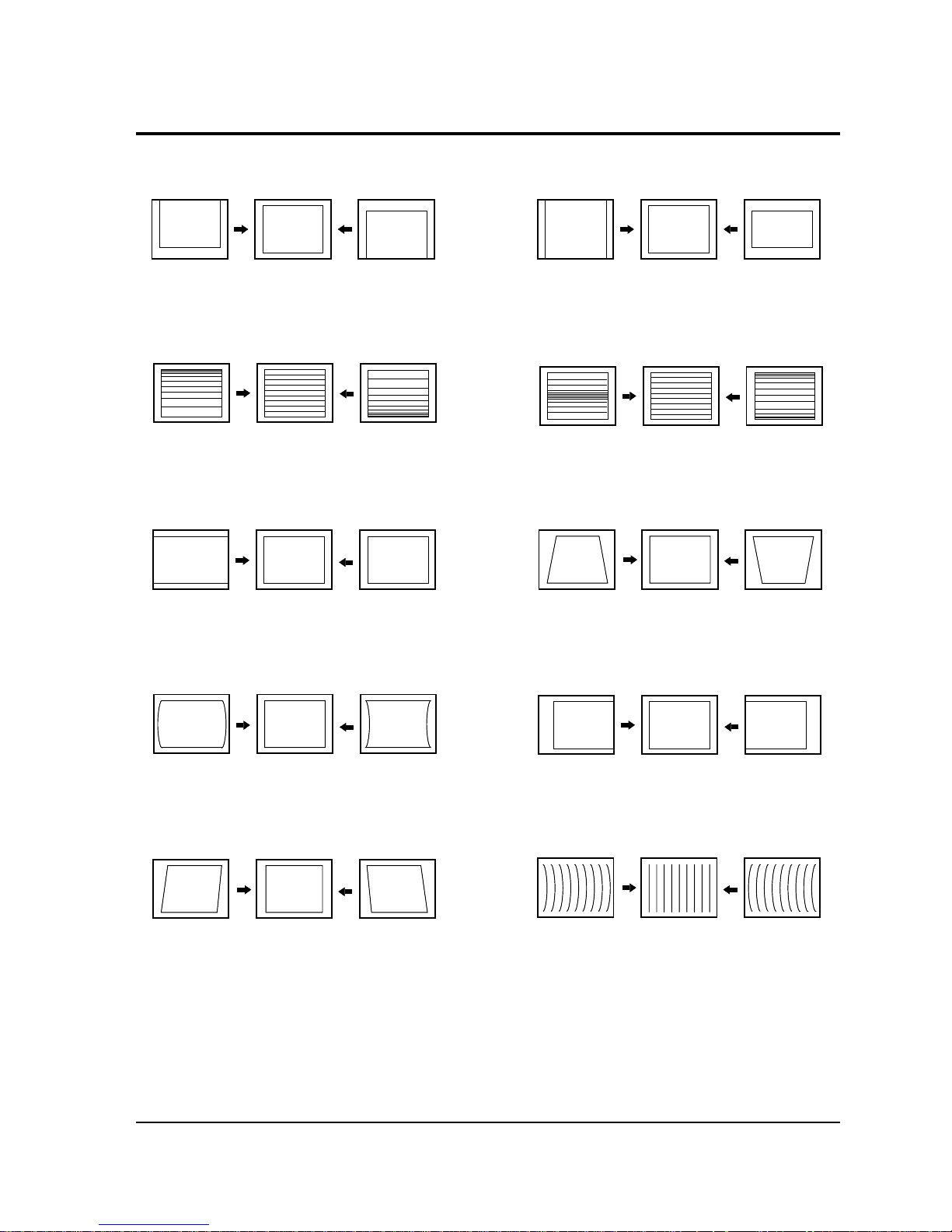
4-2 Screen Change (When adjusting I2C Bus Geometric items)
8
PIN PHASE
10 V BOW
5 V ANGLE
4
PIN AMP
2 V LINEARITY
6 V SIZE
3 H SIZE
9 H SHIFT
7 V - S - CORRECTION
1 V SHIFT
Alignment and Adjustments
4-4 Samsung Electronics
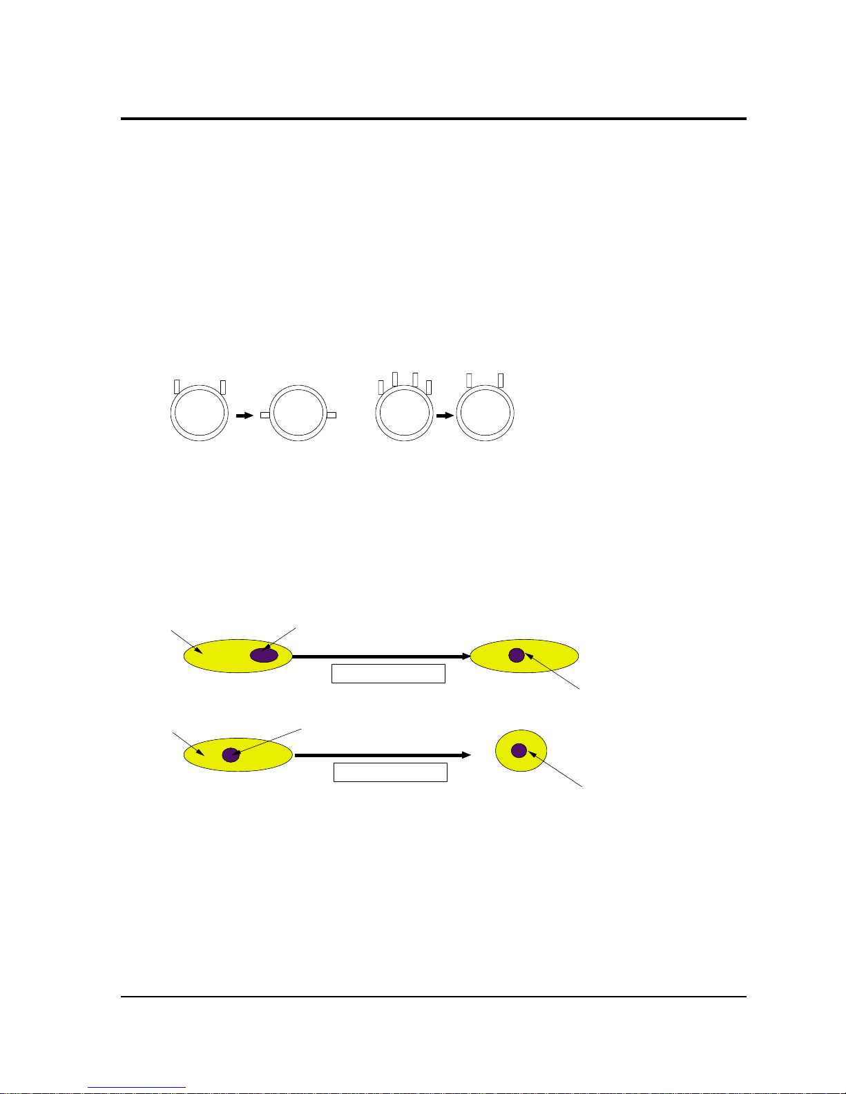
4-3 Beam Alignment
PRECAUTION
1. Input a crosshatch and dot pattern.
2. Select the “STANDARD” video mode.
3. Warm up the TV for at least 10 minutes.
4. Connect an audio oscillator to the pin jig between GT401~GT402 (located on the deflection
PCB) and GND.
5. Determine the ZERO-magnet area (using the beam-alignment CY)
6. Check the squarewave at the point where the focus is misaligned (Use an audio oscillator).
ADJUSTMENT
1. Cover the Red and Blue lenses.
2. Adjust the Green lens as shown in the figures below
3. Adjust the G-Focus until any light around the core disappears.
4. Cover the Green and Blue lenses.
5. Adjust the Red lens using the same method as with the Green lens.
6. Note: The Blue lens is not adjusted because its focus varies little (VM-coil is installed).
7. After the adjustments are completed, disconnect the jig pin connector.
(Creation of CPM Zero Magnet)
(Creation of the 2-pole/4-pole zero magnets)
G-FOCUS
CORE
(Varying G-Focus Pack)
Varying the 2-pole of VM
(Positioning the Core in the Center)
Varying the 4-pole of VM
CORE
G-FOCUS
(When VM 2-Pole Adjustment is completed)
(Adjust until the light around
the core becomes a circle)

Alignment and Adjustments
Samsung Electronics 4-5
4-4 Other Adjustments
4-4-1 Screen Adjustment
1. Warm up the TV for at least 30 minutes.
2. Turn to the Video Mode (No Signal) using a
remote-control.
3. Connect an oscilloscope to RK,GK,BK.
4. Adjust the VR (VR501, VR531, VR561) screen
so that RK, GK, BK pulse is 20Vp-p each.
(Turn the R,G,B VR screen fully
counterclockwise in the area of each flyback
line.)
4-4-2 White Balance Adjustment
1. Select the “STANDARD” video mode.
2. Input 100% white pattern.
3. In the stand-by mode, press the remote-control
keys in the following sequence:
Mute → 1 → 8 → 2 → Power ON
4. Warm up the TV for at least 30 minutes.
5. Input a 10-step signal.
6. R-cut off, B-cut off, and G-cut off by pressing
the Volume +/- keys.
7. Adjust the low light with viewing the dark
side of the screen.
8. Select R-drive, G-drive, and B-drive by
pressing the Volume +/- keys.
9. Adjust the high light with viewing the light
side of the screen.
10. If necessary, redo adjustments 6~9.
11. Press the Menu key to exit.
4-4-3 Sub-Brightness Adjustment
1. Input a sub-brightness adjustment signal.
(TOSHIBA PATTERN)
2. In the stand-by mode, press the remote-control
keys in the following sequence :
Mute - 1 - 8 - 2 - Power ON
3. Select SBT by pressing the Volume +/- keys.
4. Adjust so that the 7th step on the right side of
the screen is not seen (Use the Volume +/keys).
5. Press the Menu key to exit.
4-4-4 High Voltage (31KV) Check
PRECAUTION
1. Input a lion head pattern.
2. Select “STANDARD” video mode.
3. Warm up the TV for at least 10 minutes.
4. Use a 1000:1 probe.
ADJUSTMENT
1. Connect the (+) terminal of the 1000:1 probe to
the high voltage distributor and the (-)
terminal to GND (located on the deflection
board).
2. Adjust VR471 (located on the deflection board)
so that the digital meter indicates
DC 31V ± 0.1V.
Alignment and Adjustments
4-6 Samsung Electronics
4-4-5 F.S. (Fail Safe) Circuit Check
Note : The F.S. Circuit check must be performed
after servicing.
1. Turn on the TV.
2. Select the “STANDARD” video mode.
3. Short GT18, GT17 (located on the
Convergence PCB). Then, both sound and
picture disappear. (Note: Even if the shorted
terminals are removed, both sound and
picture do not appear. This proves the F.S.
circuit is working. )
4. To restore both sound and picture, turn off the
TV and reset it after about 30 seconds.
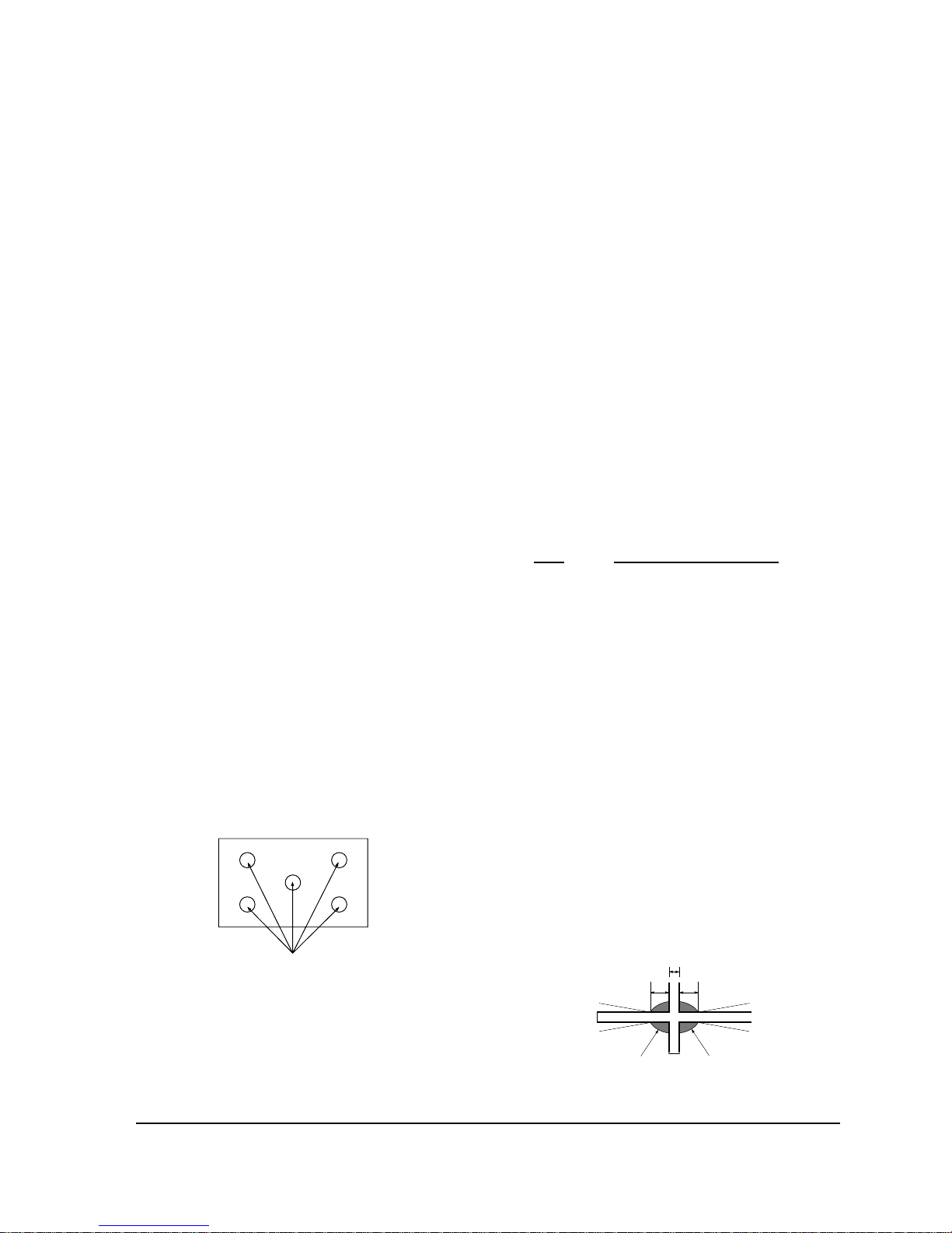
4-4-6 Static Focus Adjustment
PRECAUTION
1. Select the “STANDARD” video mode.
2. Input a crosshatch pattern.
3. Cover the lenses that are not being adjusted.
4. Connect a convergence jig and read data.
5. Adjust the lens for best focus.
(See Fig, 4-1, next page)
STATIC FOCUS (CONTINUED)
Vary the focus pack VR (Red, Blue) on the
front cabinet. Adjust the TV for best possible
focus around the center of the crosshatch
pattern, without losing overall screen balance.
Figure Crosshatch Pattern
Examine these points together.
4-4-7 Lens Focus Adjustment
PRECAUTIONS
1. Do this adjustment after the static focus
adjustment and the tilt adjustment.
2. Select the “STANDARD” video mode.
(Contrast:64, Brightness:32)
3. Input a crosshatch pattern.
ADJUSTMENT
1. Loosen the lens screws.
2. Cover the two lenses that are not being
adjusted.
3. Adjust the lens, observing the color aberration
vertically and horizontally within 3 blocks of
the center of the crosshatch pattern.
4. When the lens is turned clockwise, the color
aberration will change as follows:
Lens Color Aberration Change
R Orange - Crimson
G Blue - Red
B Purple - Green
5. Green lens adjustment:
Set the lens at the point where Blue just
changes to Red. If the color aberration is
irregular throughout the picture screen, adjust
the lens to show Red color aberration
(approximately 1~3 mm area) within a 3-block
grid around the horizontal center-line. If the
color aberration is irregular, adjust the lens as
shown in the diagram below. (Accurate
alignment of Green is important for overall
color quality.)
6. Red lens adjustment
Set the Red lens at the point where Orange
becomes Crimson.
7. Blue lens adjustment
Set the Blue lens at the point where Purple
becomes Green.
P
L1
L2
RED ABERRATION
BLUE ABERRATION
L1, L2 < P
_
Fig. 4-1 Crosshatch Pattern.
Fig. 4-2 Color Aberration
Examine these points together
Alignment and Adjustments
Samsung Electronics 4-7
4-4-8 Horizontal Dynamic Focus Adjustment
PRECAUTION
1. Input a crosshatch pattern.
2. Select the “STANDARD” video mode.
3. Warm up the set for at least 10 minutes.
ADJUSTMENT
1. Cover the Red and Blue lenses.
2. Adjust VR491 (located on the convergence
PCB, H-Parabola).
3. Balance the left and right sides of the dynamic
focus lines.
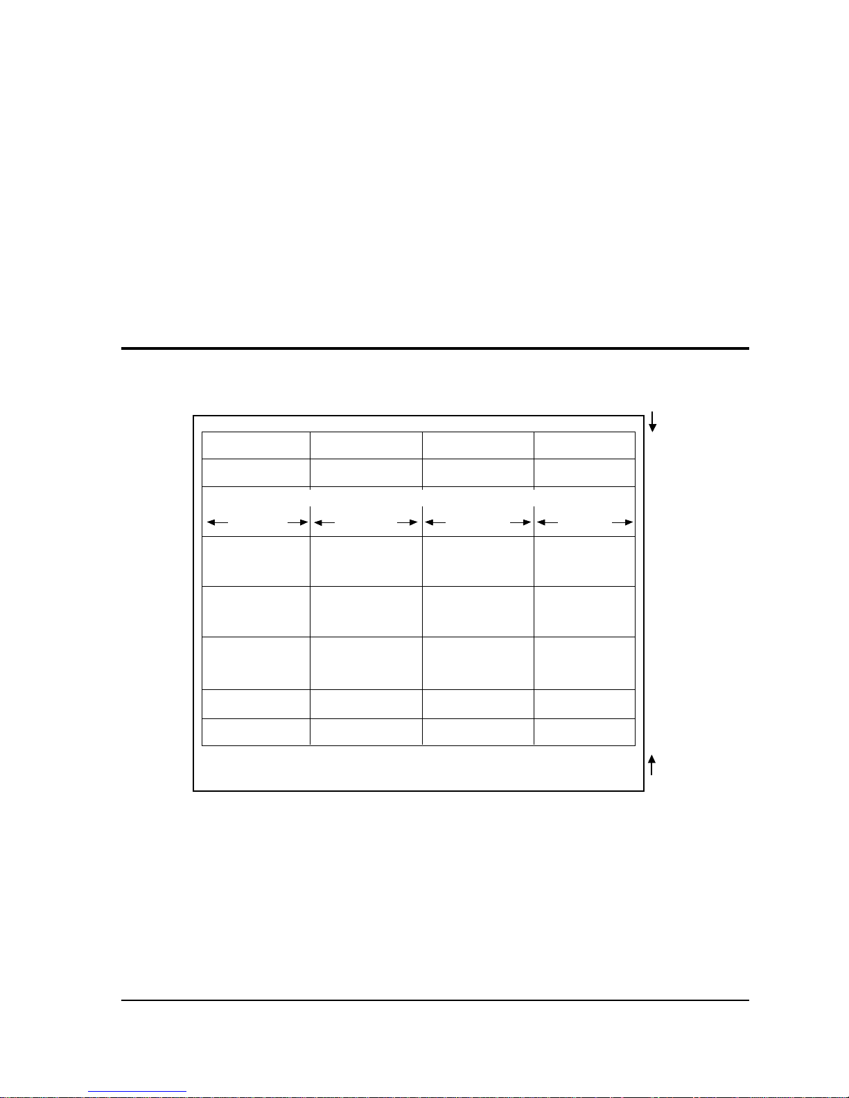
4-5 Screen-Jig
2
0.3
2.5
0.3
11
0.3
22.7
0.3
22.7
0.3
11
0.3
2.5
0.3
2
26.4 26.2
26.2 26.4
(FRONT MASK)
0.3 0.3 0.3
Unit : cm
Alignment and Adjustments
4-8 Samsung Electronics
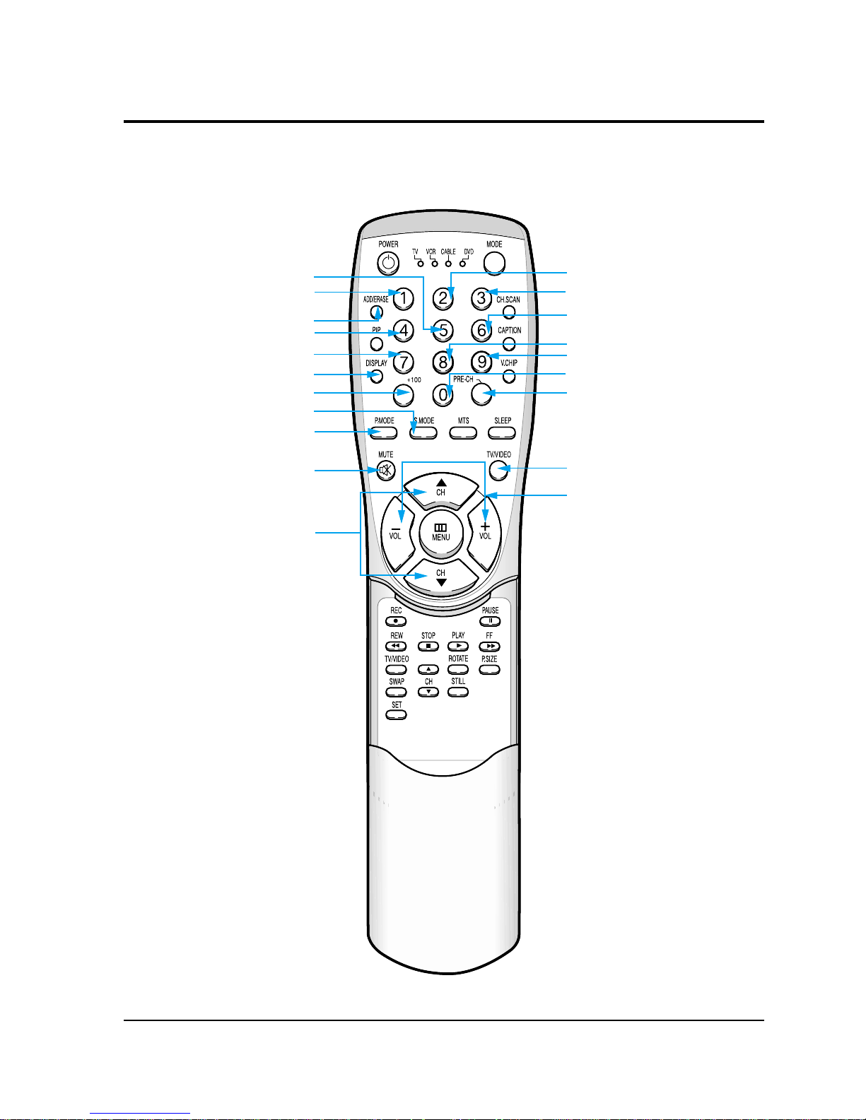
4-6 Remote Control for Servicing (Convergence Mode)
Fine Adjustment Button
Factory Data Select Button
Last Data Save Button
Half Adjustment Button
G-Mute
B-Mute
H/V Direction Select Button
Save Button
Line Shift
R-Select
R-Mute
Exit Button
Move Course Reverse
Move Course Forward
G-Select
B-Select
Convergence Picture
Move Button
Test/Noraml
Convergence data
Increase, decrease button
Convergence Data Zero Button

Alignment and Adjustments
Samsung Electronics 4-9
4-6-1 KEY Function
1. R-SELECT
Press to select RED color.
2. G-SELECT
Press to select GREEN color.
3. B-SELECT
Press to select BLUE color.
4. R-MUTE
Press to mute RED color.
5. G-MUTE
Press to mute GREEN color.
6. B-MUTE
Press to mute BLUE color.
7. CANCEL KEY
Press to revert to the previous data during the Convergence
Adjustment.
8. FINE/COARSE SELECT BUTTON
Press for minor adjustment.
If the width of the big-adjustment step is 1, then the width of the minor
adjustment step is 0.5.
9. TEST/NORMAL
Press to check TV mode in the Convergence Mode.
10. LINE SHIFT
Press to move a line up/down or left/right.
11. FACTORY DATA SELECT BUTTON
Press to call the factory default values.

Alignment and Adjustments
4-10 Samsung Electronics
12. H/V DIRECTION SELECT BUTTON
Press to switch the cursor direction horizontally or vertically.
13. SAVE BUTTON
After the Convergence Adjustments are completed, press to save data.
14. EXIT BUTTON
After the Convergence adjustments are completed, press to exit to
TV mode.
15. MOVE CURSOR FORWARD
Press to move the cursor right or down.
16. MOVE CURSOR REVERSE
Press to move the cursor left or up.
17. CONVERGENCE PICTURE MOVE BUTTON
18. CONVERGENCE DATAZERO BUTTON
Press to zero the convergence correction data.
19. HALF ADJUSTMENT BUTTON
After big adjustments are made, press for improvement of
minor adjustment.

Alignment and Adjustments
Samsung Electronics 4-11
1. Warm up the TV for at least 30 minutes.
2. Input an NTSC Signal. (Use an antenna or AV source.)
Make sure that both deflection and convergence yokes are
properly adjusted so that the center of Green, Red, Blue pattern
is aligned on the center of screen jig.
3. Enter the Convergence Mode by pressing the remote control keys in the following sequence:
If OSD is displayed as shown in figure below, press the key to exit.
Then, redo step 3 to enter the Convergence Mode.
After entering the Convergence Mode, Stand by for about five seconds before
doing the adjustments.
NOTE
NOTE
4-7 Convergence Adjustment

Alignment and Adjustments
4-12 Samsung Electronics
4. To adjust GREEN, first press the and the keys, and then press the key.
5. The key moves the cursor right, and the key moves the cursor left.

Alignment and Adjustments
Samsung Electronics 4-13
6. The key moves the cursor horizontally or vertically.
NOTE
When the key is pressed once again, the cursor moves horizontally.

Alignment and Adjustments
4-14 Samsung Electronics
7. Use the key for overall balance.
8. After the Line Shift is cancelled by pressing the key, use the Channel
and Volume keys (Up/Down) to make big adjustments.
9. After the green convergence adjustments are completed, press the key to
save the data (The minor adjustments can be done only when adjusting Red and Blue).

Alignment and Adjustments
Samsung Electronics 4-15
10. Superimpose the Red and Green colors by pressing the and
the keys.
11. To adjust RED, redo steps 5~8.
12. Use the key to make minor adjustments.
(Or the key can be used for minor adjustment.)
Cursor Movement (when making minor adjustments)

Alignment and Adjustments
4-16 Samsung Electronics
When the cursor moves vertically
13. To superimpose the blue and green colors, press (1) the key for
R-Mute, (2) the key to cancel the B-Mute, and (3) the key
for B-select.
14. To adjust BLUE, redo steps 5 ~ 8, 12.
15. If any color is not properly adjusted when displaying the red, blue and
green colors, readjust the color.
When readjusting a color, enter the minor adjustment mode.
Otherwise, the existing adjustment data might be distorted.
NOTE

Alignment and Adjustments
Samsung Electronics 4-17
16. After the color adjustments are completed, press the ( ) key to save the data.
The cursor moves to center, and then automatically moves up and
to the left about five seconds later.
17. After the Convergence Adjustments are completed, press the key to exit.
NOTE

Alignment and Adjustments
4-18 Samsung Electronics
4-8 MICOM and Pins Voltage
4-8-1 Pin Layput
POWER
IR-IN
V-MUTE
3D-SDA
N.C
CRTL 3
PROTECT
SCL 2
SDA 2
CVBS
LOOP FILTE R
ANALOG GND
SUB-AFT
KEY1
MAIN-AF T
KEY2
KEY3
ANALOG GND
HALF TONE
OSD B
ANALOG VCC
OSD G
OSD R
D2
CTRL 1
BUS-STOP
HOLD
SCL-3
SDA-3
TIMER-LED
S/W-MUTE
D1
AMP-M UTE
N.C
XTAL GND
VCC
GND
XTAL2
XTAL1
/RESET
N.C
N.C
D3
SCL-1
SDA-1
VSYNC
HSYNC
BLANK
1
2
3
4
5
6
7
8
9
10
11
12
13
14
15
16
17
18
19
20
21
22
23
24
25
26
52
51
50
49
48
47
46
45
44
43
42
41
40
39
38
37
36
35
34
33
32
31
30
29
28
27
Z
9
0
3
5
1
1
2
P
S
C
N.C
N.C
N.C
CTRL 2

Alignment and Adjustments
Samsung Electronics 4-19
4-8-2 Micom Pins
1 POWER POWER ON/OFF RELAY CONTROL H--> L
2 IR IN REMOCON INPUT 5V
3 V-MUTE VIDEO SIGNAL MUTE 3V
4 N.C N.C 5 N.C N.C 6 CRTL 3 CONTROL-3PORT 5V
7 N.C N.C 8 N.C N.C 9 PROTECT PROTECT PORT 10 N.C N.C 11 SCL 2 CLOCK BUS LINE 4.5V
12 SDA 2 DATA BUS LINE 4.5V
13 CVBS CVBS 1.7V
14 LOOP FILTER LOOP FILTER 1.9V
15 ANALOG GND GND GND
16 SUB-AFT SUB AUTO FINE TURNING CONTROL 2.64V
17 KEY 1 KEY SCAN 1 4.84V
18 MAIN-AFT MAIN TUNER AFT 1.9V
19 KEY 2 KEY SCAN 2 20 KEY 3 KEY SCAN 3 21 ANALOG GND GND 22 ANALOG VCC VCC 5V
23 HALF TONE SIGNAL FOR OSC-FREQUENCY OSD CONTROL 24 OSD B ON SCREEN DISPLAY BLUE OUTPUT 25 OSD G ON SCREEN DISPLAY GREEN OUTPUT 26 OSD R ON SCREEN DISPLAY RED OUTPUT -
PIN NO. ITEM FUNCTION OUT VOLT

Alignment and Adjustments
4-20 Samsung Electronics
27 BLANK BLAKING SIGNAL OUTPUT 28 HSYNC HORIZONTAL SYNC INPUT 29 VSYNC VERTICAL SYNC INPUT 30 SDA-1 DATA BUS LINE 4.5V
31 SCL-1 CLOCK BUS LINE 4.12V
32 D3 CONVERGENCE D3 33 N.C N.C 34 N.C N.C 35 /RESET RESET 4.74V
36 XTAL1 XTAL 1 1.72V
37 XTAL2 XTAL 2 2.2V
38 GND GND 39 VCC VCC 5V
40 XTAL GND GND 41 N.C N.C 42 CRTL 2 CONTROL - 2 PORT 5V
43 AMP-MUTE MAIN AMP MUTE 44 D1 CONVERGENCE D1 45 S/W-MUTE SWITCH MUTE (NOT USED) 46 TIMER-LED TIMER LED 4.7V
47 SDA-3 DATA BUS LINE 4.6V
48 SCL-3 CLOCK BUS LINE 4.6V
49 HOLD HOLD 4.65V
50 BUS-STOP I2C BUS STOP 5V
51 CRTL 1 CONTROL - 1 PORT 4.65V
52 D2 CONVERGENCE D2 -
PIN NO. ITEM FUNCTION OUT VOLT

Alignment and Adjustments
Samsung Electronics 4-21
4-8-3 Chroma MDL
1 N.C N.C 2 GND GND GND
3 CVBS/Y CVBS/Y INPUT 1.76V
4 CIN C-INPUT 2.92V
5 GND GND GND
6 E-Pr/R E-Pr/R INPUT 2.0V
7 E-Y/G E-Y/G INPUT 2.0V
8 E-Pb/B E-Pb/B INPUT 2.0V
9 E-FB FAST BLANKING INPUT 0.25V
10 GND GND GND
11 HS1 1H-SYNC OUT 12 VS1 VS1 OUT 13 GND GND GND
14 SDA-2 SERIAL DATA LINE 2 4.7V
15 SCL-2 SERIAL CLOCK LINE 2 4.8V
16 N.C N.C 17 HD H-DRIVE OUT 1.6V
18 H-BLK H-BLANK INPUT 19 VD+ VERTICAL DRIVE (+VOLTAGE) 2.90V
20 VD- VERTICAL DRIVE (-VOLTAGE) 2.95V
21 ABL ABL INPUT 2.15V
22 V-BLK V-BLANKING 23 EW EAST WEST OUT 2.2V
24 N.C N.C 25 GND GND GND
26 N.C N.C 27 FSC FSC 28 HC 5V INPUT 29 GND GND GND
30 TEST-Y WHEN CG ADJ PATTERN INPUT -
PIN NO. ITEM FUNCTION OUT VOLT

Alignment and Adjustments
4-22 Samsung Electronics
31 N.C N.C 32 N.C N.C 33 N.C N.C 34 CRTL - 3 CRTL - 3 5V
35 CRTL - 1 CRTL - 1 5V
36 GND GND GND
37 OSD-R OSD-R INPUT 38 OSD-G OSD-G INPUT 39 OSD-B OSD-B INPUT 40 YS BLANK(MICOM OUT) 41 YM HALF TONE INPUT 42 V-MUTE VIDEO MUTE (V-CHIP ON) 4.72V
43 GND GND GND
44 9V 9V 9V
45 N.C N.C 46 N.C N.C 47 N.C N.C 48 PIP-F/B N.C 49 GND GND
50 R-OUT R-OUT 51 G-OUT G-OUT 52 B-OUT B-OUT 53 GND GND GND
54 IK IK OUT 3.65V
55 SPOT SPOT OUT 56 GND GND GND
57 VM-Y VM-Y OUT 5.42V
58 CTRL - 2 CTRL - 2 5V
PIN NO. ITEM FUNCTION OUT VOLT

Alignment and Adjustments
Samsung Electronics 4-23
4-8-4 PIP MODULE
1 GND GND GND
2 TV SUB-V INPUT 2.93V
3 GND GND GND
4 N.C N.C 5 8V 8V INPUT 8V
6 N.C N.C 7 PIP-Pr/R PIP-Pr/R (DVD SIG) OUT 2.02V
8 PIP-Y/G PIP-Y/G (DVD SIG) OUT 2.04V
9 PIP-Pb/B PIP-Pb/B (DVD SIG) OUT 2.02V
10 PIP-FB PIP FAST BLANKING 2.02V
11 12V 12V INPUT 12V
12 PIP-F/B N.C N.C
13 PIP-B DVD-B IN 14 PIP-G DVD-G IN 15 PIP-R DVD-R IN 16 N.C N.C 17 V-SYNC V-SYNC INPUT 18 H-SYNC H-SYNC INPUT 19 SCL SERIAL CLOCK LINE 4.11V
20 SDA SERIAL DATA LINE 4.5V
21 5V 5V INPUT 5V
22 GND GND GND
PIN NO. ITEM FUNCTION OUT VOLT

Alignment and Adjustments
4-24 Samsung Electronics
4-8-5 2D/COMB MODULE
1 VIDEO MAIN VIDEO INPUT 2.74V
2 GND GND GND
3 9V 9V INPUT 9V
4 GND GND GND
5 FSC FSC 6 N.C N.C 7 N.C N.C 8 5V 5V INPUT 5V
9 Y-OUT MAIN Y OUT 10 GND GND GND
11 C-OUT MAIN C OUT 12 GND GND GND
1 SIF SIF OUT 3.25V
2 9V 9V INPUT 9V
3 GND GND GND
4 IF IF INPUT 4.5V
5 GND GND GND
6 AGC RF AGC IN 5.37V
7 TV-VIDEO TV-VIDEO OUT 8 AFT MAIN AFT INPUT 2V
9 GND GND GND
PIN NO. ITEM FUNCTION OUT VOLT
PIN NO. ITEM FUNCTION OUT VOLT
4-8-6 IF MODULE

Alignment and Adjustments
Samsung Electronics 4-25
4-8-7 MTS MODULE
PIN NO. ITEM FUNCTION OUT VOLT
1 TV-R TV R-SOUND OUT 2 TV-L TV L-SOUND OUT 3 SCL SERIAL CLOCK LINE 4 SDA SERIAL DATA LINE 5 N.C N.C 6 GND GND GND
7 SIF SIF INPUT 8 N.C N.C 9 N.C N.C 10 9V 9V INPUT 9V

Alignment and Adjustments
4-26 Samsung Electronics
4-8-8 H/V MODULE
1 12V 12V INPUT 12V
2 GND GND GND
3 HD H-DRIVE INPUT 1.6V
4 V-BLK V-BLANK INPUT 0.72V
5 H-BLK H-BLANK OUT 0.54V
6 GND GND GND
7 PROTECT PROTECT ACTIV H
8 FBT-DC FBT DC FEED BACK 4.87V
9 X-RAY X-RAY PROTECT F/B 2.10V
10 N.C N.C 11 HV-REG HV-REG 3.54V
12 HV-DRIVE HIGH VOLTAGE DRIVE 0.32V
13 H-DRIVE H-DRIVE OUT 25V
14 GND GND GND
15 HEATER HEATER INPUT AC[0.7V]
16 N.C N.C 17 208V 208V INPUT 208V
18 N.C N.C 19 GND GND GND
20 V2 V2 INPUT
21 N.C N.C 22 N.C N.C 23 D-FOCUS DYNAMIC FOCUS OUT 24 N.C N.C 25 N.C N.C 26 SCREEN SCREEN INPUT 1356V
PIN NO. ITEM FUNCTION OUT VOLT

Alignment and Adjustments
Samsung Electronics 4-27
4-8-9 CONV- MODULE
1 SDA D2 2 SCL D1 3 GND GND GND
4 BV BLUE VERTICAL OUT 5 BH BLUE HORIZONTAL OUT 6 GV GREEN VERTICAL OUT 7 GH GREEN HORIZONTAL OUT 8 RV RED VERTICAL OUT 9 RH RED HORIZONTAL OUT 10 -5.4V -5.4V INPUT -5.4V
11 5.4V 5.4V INPUT +5.4V
12 V-BLK V-BLK INPUT 13 GND GND GND
14 H-BLK H-BLK INPUT 0.52V
15 COMP COMP VIDEO OUTPUT (N.C) 16 IR INPUT REMOCON 3V
17 CTRL CTRL (N.C) N.C
18 D3/SEL D3 0.2V
19 B WHEN TEST PATTERN B OUT 20 G(TEST) WHEN TEST PATTERN G OUT N.C
21 R WHEN TEST PATTERN R OUT 22 SYNC SYNC OUTPUT 4.41V
PIN NO. ITEM FUNCTION OUT VOLT

4-28 Samsung Electronics
MEMO

Troubleshooting
Samsung Electronics 5-1
5. Troubleshooting
5-1 Convergence Misaligned

5-2 No Sound
Troubleshooting
5-2 Samsung Electronics

Troubleshooting
Samsung Electronics 5-3
5-3 No Raster (Sound OK)

MEMO
5-4 Samsung Electronics

6. Exploded View & Parts List
6-1 PCJ522R
Exploded View & Parts List
Samsung Electronics 6-1
1 ASSY-CABINET,FRONT AA91-10419M HIPS HB BLK 1
1-1 SUN-SCREEN AA67-70048A 52 PMMA 1
1-2 SCREEN-TINT AA67-70065A 52 DNP 1
1-3 HOLDER-SCREEN AA61-00081B A6063 EXTR. L754 2
1-4 SCREW-TAPTITE AA60-10011A HH + M4 L12 ZPC 24
1-5 HOLDER-SCREEN AA61-00081C A6063 EXTR. L1052 2
1-6 SCREW-WOOD AA60-10050W W/H + M4 L20 ZPC 4
1-7 SCREW-TAPPING AA60-10002A RH + M4 L12 ZPC OD14 2
1-8 ASSY-PCB,CONTROL AA95-00265B P51A 1
1-9 ASSY-PCB,A/V FRONT AA95-00290C P51A 1
1-10 SCREW-TAPTITE AA60-10011A HH + M4 L12 ZPC 2
2 CABINET-FRONT,BOTTOM AA64-31357A ABS V0 BLK 1
2-1 SCREW-TAPTITE AA60-10011A HH + M4 L12 ZPC 3
3 ASSY-CABINET,MID AA91-00205A WOOD 1
3-1 SCREW-WOOD AA60-10051A PH + M4 L16 ZPC 24
3-2 SPEAKER 3001-001107 20W 8ohm 95+-2DB 2
3-3 SPEAKER 3001-000176 30W 8ohm 93+-2DB 2
3-4 SCREW-WOOD AA60-10050W W/H + M4 L20 ZPC 2
3-5 MODULE-FOCUS,PACK AA59-40003P F300,NTSC,43,64x62, 1
4 CABINET-BACK,TOP AA64-30714A HIPS HB BLK 1
4-1 SCREW-TAPTITE 6003-001026 RH + M4 L15 ZPC 16
4-2 BRACKET-MIRROR,C AA61-10242A SECC T1.0 2
4-3 BRACKET-MIRROR AA61-10361A SECC T1.0 5
4-4 SPACER-MIRROR AA63-00021G PVC BLK L420 2
4-5 MIRROR-BACK SURFACE AA67-20026A 52 GLASS T3 1
4-6 SPACER-MIRROR AA63-00021G PVC BLK L970 1
4-7 SPACER-MIRROR AA63-00021G PVC BLK L680 1
4-8 SCREW-WOOD AA60-10050W W/H + M4 L20 ZPC 8
5 CABINET-BACK,BOARD AA64-00501A HIPS V0 BLK 1
5-1 SCREW-WOOD AA60-10050W W/H + M4 L20 ZPC 14
5-2 LABEL-WARNING AA68-00233A A/P 90(G) 1
6 ASSY-BRACKET,MAIN AA91-00241A SECC T1.6 1
6-1 SCREW-ASSY AA60-10001A WP + M6 L20 SCM30C 4
6-2 SCREW-TAPTITE AA60-10011A HH + M4 L12 ZPC 1
6-3 ASSY-CRT(R) AA94-01640A P16LNM07RJA,+380MG,7,BARE 1
ASSY-CRT(G) AA94-01641A 16LNM07HKA,+380MG,7,BARE 1
ASSY-CRT(B) AA94-01642A P16LNM07BMB,+380MG,7,BARE, 1
6-4 SPACER-COVER,DUST AA60-00027A SPONGE T2 1
7 HOLDER-CHASSIS AA61-00051B ABS V0 GRAY 1
7-1 ASSY-PCB,MAIN(OPT) AA94-01636A PCJ522RX/XAA,P51A,U.S 1
7-2 ASSY-PCB,SUB AA94-01636A PCJ522RX/XAA,P51A,U.S 1
7-3 ASSY-CONV.AMP AA95-00055E P51A 1
7-4 SCREW-TAPPING 6003-001023 RWH + B M3 L10 ZPC 21
7-5 ASSY-TERMINAL,BOARD AA91-00158H HIPS V0 VLK 1
DESCRIPTION CODE - NO SPECIFICATION Q’TYNo.

1 ASS`Y-CABINET,MASK AA91-00140E HB BLK SEA PCJ612R 1
2 SUN-SCREEN AA67-70057A 61’ DNP 1283*973 1
3 SCREEN-TINT AA67-70056A 61’ DNP 1283*973 1
4 HOLDER-SCREEN AA61-00079C PCJ613R ABS HB BLK L945 2
5 HOLDER-SCREEN AA61-00079B PCJ613R ABS HB BLK L1255 2
6 COVER-FRONT,WOOD AA63-00183A WOOD 612R 2
7 ASS`Y-CABINET,BOT AA91-00014G VO DG707M ALL PCJ612R 1
8 ASSY-PCB,CONTROL AA95-00265B P51A 1
9 ASSY-PCB,A/V FRONT AA95-00290L P51A 1
10 SPEAKER 3001-001107 20W 8ohm 95+-2DB 1
11 SPEAKER 3001-000176 30W 8ohm 93+-2DB 1
12 SCREW-TAPTITE 6003-001023 RWH + M3 L10 ZPC(YEL) 2
13 MODULE FOCUS-PACK AA59-40003P F300,NTSC,43,64X62,BK 1
14 ASS`Y-CABINET,MIDDLE AA91-00207A WOOD PCJ612R 1
15 SPACER-COVER,DUST AA60-00027B SPONGE T2.0 612R 1
16 ASSY-CRT(R) AA94-01676A P16LNM07RJA,+380MG,7,BARE, 1
17 ASSY-CRT(G) AA94-01677A P16LNM07HKA,+380MG,7,BARE, 1
18 ASSY-CRT(B) AA94-01678A P16LNM07BMB,+380MG,7,BARE 1
19 ASS`Y-BRACKET,MAIN AA91-00241A SECC T1.6 7 53J5 1
20 SCREW-TAPTITE AA60-10011A PC M4 L12 ZPC(BLK) 8
21 MIRROR-BACK AA67-00020A GLASS T3.0 1160*754*806 1
22 COVER-MIRROR,WOOD AA63-00082A PCH613R WOOD 1
23 SCREW-WOOD AA60-10050W 10/H M4 L20 ZPC(BLK) 1
24 SCREW-WOOD 6005-001001 TH M4 L28 BLK SWRCH 18A 1
25 CABINET-BACK,TOP AA4-31213B HIPS HB BLK 1
26 SCREW-WOOD AA60-10050W W/H M4 20 ZPC(BLK) 13
27 CABINET-BACK,BOARD AA64-00625A HIPS VO BLK T3.0 1
28 ASSY-CONV,AMP AA95-00055E P51A 1
29 ASSY-SUB AA95-00053F P51A 1
30 ASSY-MAIN AA95-00055E P51A 1
31 ASS`Y-TERMINAL,BOARD AA91-00158H HIPS VO BLK PCJ612R 1
32 HOLDER-CHASSIS AA61-00051B ABS VO GRAY E2 1
DESCRIPTION CODE - NO SPECIFICATION Q’TYNo.
Exploded View & Parts List
6-2 Samsung Electronics
6-2 PCJ612R

7. Electrical Parts List
Electrical Parts List
Samsung Electronics 7-1
ASSY-CABINET
*AA90-00186ASSY-CABINET;612R,PCJ612RX/XAA
SPC AA60-00027BSPACER-COVER,DUST;SPONGE,T2.0,-,-,612R,HDR AA61-00079BHOLDER-SCREEN;-,PCJ613R,ABS,HB,BLK,L1255
HDR AA61-00079CHOLDER-SCREEN;-,PCJ613R,ABS,HB,BLK,L945
COVM AA63-00082ACOVER-MIRROR,WOOD;-,PCJ613R,-,WOOD,-,-,-,COVF AA63-00183ACOVER-FRONT,WOOD;-,PCJ612R,JERSEY,WOOD,-,-,-,SPA AA63-60131ESPACER-FELT;FELT,T0.5,BLK,520X200,PCJ612R,BACK AA64-00625ACABINET-BACK,BOARD;-,613R,-,HIPS,V0,BLK,T3.0,BACK AA64-31213BCABINET-BACK,TOP;-,555J,-,HIPS,HB,BLK,-,MIRB AA67-00020AMIRROR-BACK;613,GLASS,T3.0,-,-,1160*754*806,BSM,SUN AA67-00022ASUN-SCREEN;-,61,H/C,A/S,PMMA,T=82%,T2.0,1283*973,SCRN AA67-70056ASCREEN-TINT;0.515,61’,DNP,896-
985,TINT10%,2.7,1283*973,
AC+BCM AA60-10011ASCREW-TAPTITE;HH,+,PC,M4,L12,ZPC(BLK),SWRCH1
ACB+CM AA60-10050 SCREW-WOOD;W/H,+,M4,20,ZPC(BLK),SWRCH18A,
AV+CFB AA60-10002ASCREW-TAPPING;RH,+,M4,L12,ZPC(YEL),-,OD14
BCM AA63-60040BSPACER-DIECAST;PU,-,-,225X23,S4388,BCM+CM AA60-00015ASCREW-ASSY;-,WP,-,M8,L25,SCM30C,-,CMW AA60-10050 SCREW-WOOD;W/H,+,M4,20,ZPC(BLK),SWRCH18A,
CMW+CM 6005-001001 SCREW-WOOD;TH,+,M4,L28,BLK,SWRCH18A
CP+CFB AA60-10002ASCREW-TAPPING;RH,+,M4,L12,ZPC(YEL),-,OD14
FP+BF 6003-001023 SCREW-TAPTITE;RWH,+,B,M3,L10,ZPC(YEL),SWRCH1
HC+CM AA60-10050 SCREW-WOOD;W/H,+,M4,20,ZPC(BLK),SWRCH18A,
HS+CM AA60-00021ASCREW-WOOD;RH,+,M3.5,L22,ZPC(BLK),SWRCH18,HSS+CM AA60-00021ASCREW-WOOD;RH,+,M3.5,L22,ZPC(BLK),SWRCH18,HV+BCM 6003-001024 SCREW-TAPTITE;RWH,+,B,M4,L12,ZPC(YEL),SWRCH1
RNGBCM 6003-001024 SCREW-TAPTITE;RWH,+,B,M4,L12,ZPC(YEL),SWRCH1
TBACBW 6003-001024 SCREW-TAPTITE;RWH,+,B,M4,L12,ZPC(YEL),SWRCH1
VBW+CM AA60-10050 SCREW-WOOD;W/H,+,M4,20,ZPC(BLK),SWRCH18A,
ASSY-CABINET,BOT
* AA91-00014GASSY-CABINET,BOT;-,V0,DG707M ALL,PCJ612R
BADGE AA64-00406EBADGE-BRAND;AL,DG-707M SAMSUNG,SILVER,72,FORG
ING,-,CAFRBOT AA61-30001ALATCH-DOOR;-,-,-,KIFUCO LA701,CAFRBOT AA61-60005ASPRING-CS;-,SUS304,0.6,OD10.7,H10,N4,-,CAFRBOT AA64-10764BKNOB-CONTROL;-,-,CHAMPAINE GOLD+UV,ABS ,HB,NTR
CAFRBOT AA64-40494AWINDOW-REMOCON;-,SVP-434J,-,PC,-,VIOLET,DOOR AA64-00090DDOOR-A/V;-,PCJ612R,DG707M ALL,ABS,HB,BLK,-,FRONT AA64-00088JCABINET-FRONT,BOT;-,PCJ612R,DG707M
SEA,SECA,HIPS,V0,BLK,-,-
KC+CFB 6003-001022 SCREW-TAPTITE;RH,+,B,M3,L12,ZPC(BLK),SWRCH18
LAB AA68-00046CLABEL-DOOR,AV;TETRON MAT P,E,PCJ533R,P51A EL,-,-,WIN AA64-40493AINDICATOR-LED;-,SVP-434JA,-,ABS,-,CLR,WR+CFB 6003-001022 SCREW-TAPTITE;RH,+,B,M3,L12,ZPC(BLK),SWRCH18
ASSY-CABINET,MASK
* AA91-00140EASSY-CABINET,MASK;-,HB,BLK,DG902+BK901
SEA,PCJ612R
FRONT AA64-00257BCABINET-FRONT,MASK;-,PCJ613R,L1251,ABS,HB,BLK,-,-
FRONT AA64-00257CCABINET-FRONT,SIDE;-,PCJ613R,L941,ABS,HB,BLK,-,HDRC AA61-00078BHOLDER-CORNER;-,PCJ613R,ABS,HB,BLK,-
SPA AA63-00063ASPACER-DUAL,LOCK;#400,-,-,19X19,SVP-614J,-
ASSY-CABINET,MIDDLE
* AA91-00207AASSY-CABINET,MIDDLE;-,WOOD,-,PCJ612R
AL 2401-003493 C-AL;1.75uF,10%,100V,BP,BK,10x13mm,5
BCKT AA61-10247ABRACKET-FOCUS;-,S46DS,SECC,T1.0,-,-,BF+CM AA60-10051ASCREW-WOOD;PH,+,M4,L16,ZPC(BLK),SWRCH18A,
CABMID AA64-00514ACABINET-MIDDLE;-,PCJ612R,-,WOOD,-,BLK,-,CABMID 3001-000153 SPEAKER;20W,8ohm,93dB,1.3KHz
CABMID 3001-000176 SPEAKER;30W,8OHM,93DB+-2DB,65HZ
CABMID AA61-00030ACASTER;SVP-614JM,POLYURETHANE,-,50,23,-,H63,CABMID AA61-00080BHOLDER-MASK;-,PCJ613R,ABS,HB,NTR,L80
CABMID AA63-00105ASPACER-FELT;FELT,T2.0,BLK,32X878,PCJ613R,CABMID AA63-00105BSPACER-FELT;FELT,T2.0,BLK,32X1211,PCJ613R,HDRP AA61-00146AHOLDER-PIN,LOCKER;-,PRJT,ABS,HB,BLK,WOOD
LEAD AA39-20609ALEAD CONNECTOR-ASSY;-,SMH250-
02,REC,2P,400mm,1007#
SPA AA63-00066BSPACER-DUAL,LOCK;#250,-,-,11X25,PROJECTION,SPAF AA63-60126ASPACER-FELT;FELT,T2,BLK,1160X15,PRJT43,52,
SPAF AA63-60126DSPACER-FELT;FELT,T2,-,400X15,PRJ61,SPK AA39-20505RLEAD CONNECTOR-ASSY;-,YSH250-
04,REC,4P,1400,900,1007#22
ASSY-CRT-(R)
* AA94-01676AASSY-CRT-(R);P16LNM07RJA,+380MG,7,BARE,PCJ612R,-
LENS AA67-10066ALENS-ASSY;DELTA 37,-,-,CLEAR A/B,-,-,-
ASSY-CRT-(G)
* AA94-01677AASSY-CRT-(G);P16LNM07HKA,+380MG,7,BARE,PCJ612R,-
LENS AA67-10066ALENS-ASSY;DELTA 37,-,-,CLEAR A/B,-,-,-
ASSY-CRT-(B)
* AA94-01678AASSY-CRT-(B);P16LNM07BMB,+380MG,7,BARE,PCJ612R,-
LENS AA67-10066ALENS-ASSY;DELTA 37,-,-,CLEAR A/B,-,-,-
ASSY-PCB,CRT
* AA95-00344DASSY-PCB,CRT;-,P51A,-,USA,PCJ612R
BDW-GND AA39-20009KLEAD CONNECTOR-ASSY;-,YFH800-01,-
,1P,1617#22,1000MM
CNW401 AA39-20027DLEAD-CONNECTOR,ASSY;-,67096-006,S,6P,600,1007#26
CNW501 AA39-20030DLEAD-CONNECTOR,ASSY;-,67096-008,S,8P,600,1007#26
GDW-GND AA39-20009GLEAD-CONNECTOR,ASSY;-,YFH800-01,-,1P,700,1617#22
RDW-GND AA39-20009CLEAD CONNECTOR-ASSY;-,YFH800-01,-,1P,400,1617#22
Loc. No. Code No. Description ; Specification Remark Loc. No. Code No. Description ; Specification Remark
7-1 PCJ612RX/XAA (PCJ522RX/XAA and PCJ612RX/XAA Dissimilar Parts)

Electrical Parts List
7-2 Samsung Electronics
ASSY-CABINET,FRONT
* AA91-00251AASSY-CABINET,FRONT;-,524J,D703+B702
COMPAC,HB,BLK
CMPRTVFRONTTOPAA64-31356NCABINET-FRONT,TOP;-,524J,D703+B702
C/THEATRE,HIPS,HB,BLK,-,-
ASSY-ACCESSORY
* AA94-01639AASSY-ACCESSORY;PCJ522RX/XAC,P51A,CANADA,SECA
CMPRTV IBAA68-00533AMANUAL-USERS;P51A,W/P100(G),-,FRE,-,-,B5,-,-
Loc. No. Code No. Description ; Specification Remark Loc. No. Code No. Description ; Specification Remark
7-2 PCJ522RX/XAC (PCJ522RX/XAA and PCJ522RX/XAC Dissimilar Parts)
ASSY-CABINET
* AA90-00186AASSY-CABINET;612R,PCJ612RX/XAC
AC+BCM AA60-10011ASCREW-TAPTITE;HH,+,PC,M4,L12,ZPC(BLK),SWRCH1
ACB+CM AA60-10050WSCREW-WOOD;W/H,+,M4,20,ZPC(BLK),SWRCH18A,
AP2273 AA68-50509ALABEL-BOX;A/P 90(G),ALL MODEL,-,WHT,L250
AV+CFB AA60-10002ASCREW-TAPPING;RH,+,M4,L12,ZPC(YEL),-,OD14
BACK AA64-00625ACABINET-BACK,BOARD;-,613R,-,HIPS,V0,BLK,T3.0,BACK AA64-31213BCABINET-BACK,TOP;-,555J,-,HIPS,HB,BLK,-,BCM AA63-60040BSPACER-DIECAST;PU,-,-,225X23,S4388,BCM+CM AA60-00015ASCREW-ASSY;-,WP,-,M8,L25,SCM30C,-,CMW AA60-10050WSCREW-WOOD;W/H,+,M4,20,ZPC(BLK),SWRCH18A,
CMW+CM 6005-001001 SCREW-WOOD;TH,+,M4,L28,BLK,SWRCH18A
COVERF AA63-00183ACOVER-FRONT,WOOD;-,PCJ612R,JERSEY,WOOD,-,-,-,COVERM AA63-00082ACOVER-MIRROR,WOOD;-,PCJ613R,-,WOOD,-,-,-,CP+CFB AA60-10002ASCREW-TAPPING;RH,+,M4,L12,ZPC(YEL),-,OD14
FP+BF 6003-001023 SCREW-TAPTITE;RWH,+,B,M3,L10,ZPC(YEL),SWRCH1
HC+CM AA60-10050WSCREW-WOOD;W/H,+,M4,20,ZPC(BLK),SWRCH18A,
HDRS AA61-00079BHOLDER-SCREEN;-,PCJ613R,ABS,HB,BLK,L1255
HDRS AA61-00079CHOLDER-SCREEN;-,PCJ613R,ABS,HB,BLK,L945
HS+CM AA60-00021ASCREW-WOOD;RH,+,M3.5,L22,ZPC(BLK),SWRCH18,HSS+CM AA60-00021ASCREW-WOOD;RH,+,M3.5,L22,ZPC(BLK),SWRCH18,HV+BCM 6003-001024 SCREW-TAPTITE;RWH,+,B,M4,L12,ZPC(YEL),SWRCH1
MIRB AA67-00020AMIRROR-BACK;613,GLASS,T3.0,-,-,1160*754*806,BSM,RNGBCM 6003-001024 SCREW-TAPTITE;RWH,+,B,M4,L12,ZPC(YEL),SWRCH1
SCRT AA67-70056ASCREEN-TINT;0.515,61’,DNP,896-
985,TINT10%,2.7,1283*973,
SPA AA60-00027BSPACER-COVER,DUST;SPONGE,T2.0,-,-,612R,SPA AA63-60131ESPACER-FELT;FELT,T0.5,BLK,520X200,PCJ612R,SUN AA67-00022ASUN-SCREEN;-,61,H/C,A/S,PMMA,T=82%,T2.0,1283*973,TBACBW 6003-001024 SCREW-TAPTITE;RWH,+,B,M4,L12,ZPC(YEL),SWRCH1
VBW+CM AA60-10050WSCREW-WOOD;W/H,+,M4,20,ZPC(BLK),SWRCH18A,
ASSY-CABINET,BOT
* AA91-00014GASSY-CABINET,BOT;-,V0,DG707M ALL,PCJ612R
BADGE AA64-00406EBADGE-BRAND;AL,DG-707M SAMSUNG,SILVER,72,FORG
ING,-,CAFRBOT AA61-30001ALATCH-DOOR;-,-,-,KIFUCO LA701,CAFRBOT AA61-60005ASPRING-CS;-,SUS304,0.6,OD10.7,H10,N4,-,CAFRBOT AA64-10764BKNOB-CONTROL;-,-,CHAMPAINE GOLD+UV,ABS ,HB,NTR
CAFRBOT AA64-40494AWINDOW-REMOCON;-,SVP-434J,-,PC,-,VIOLET,DOORAV AA64-00090DDOOR-A/V;-,PCJ612R,DG707M ALL,ABS,HB,BLK,-,FRONT AA64-00088JCABINET-FRONT,BOT;-,PCJ612R,DG707M
SEA,SECA,HIPS,V0,BLK,-,KC+CFB 6003-001022 SCREW-TAPTITE;RH,+,B,M3,L12,ZPC(BLK),SWRCH18
LABEL AA68-00046CLABEL-DOOR,AV;TETRON MAT P,E,PCJ533R,P51A EL,-,-,WIN AA64-40493AINDICATOR-LED;-,SVP-434JA,-,ABS,-,CLR,WR+CFB 6003-001022 SCREW-TAPTITE;RH,+,B,M3,L12,ZPC(BLK),SWRCH18
ASSY-CABINET,MASK
* AA91-00140DASSY-CABINET,MASK;-,HB,BLK,DG902+BK901
SECA,PCJ612R
FRONT AA64-00257BCABINET-FRONT,MASK;-,PCJ613R,L1251,ABS,HB,BLK,-,FRONT AA64-00257CCABINET-FRONT,SIDE;-,PCJ613R,L941,ABS,HB,BLK,-,HDR AA61-00078BHOLDER-CORNER;-,PCJ613R,ABS,HB,BLK,SPA AA63-00063ASPACER-DUAL,LOCK;#400,-,-,19X19,SVP-614J,-
ASSY-CABINET,MIDDLE
* AA91-00207AASSY-CABINET,MIDDLE;-,WOOD,-,PCJ612R
AL 2401-003493 C-AL;1.75uF,10%,100V,BP,BK,10x13mm,5
BCKT AA61-10247ABRACKET-FOCUS;-,S46DS,SECC,T1.0,-,-,BF+CM AA60-10051ASCREW-WOOD;PH,+,M4,L16,ZPC(BLK),SWRCH18A,
CABMID 3001-000153 SPEAKER;20W,8ohm,93dB,1.3KHz
CABMID 3001-000176 SPEAKER;30W,8OHM,93DB+-2DB,65HZ
CABMID AA61-00030ACASTER;SVP-614JM,POLYURETHANE,-,50,23,-,H63,CABMID AA61-00080BHOLDER-MASK;-,PCJ613R,ABS,HB,NTR,L80
CABMID AA63-00105ASPACER-FELT;FELT,T2.0,BLK,32X878,PCJ613R,CABMID AA63-00105BSPACER-FELT;FELT,T2.0,BLK,32X1211,PCJ613R,HDR AA61-00146AHOLDER-PIN,LOCKER;-,PRJT,ABS,HB,BLK,WOOD
LEAD AA39-20609ALEAD CONNECTOR-ASSY;-,SMH250-
02,REC,2P,400mm,1007#
MIDCAB AA64-00514ACABINET-MIDDLE;-,PCJ612R,-,WOOD,-,BLK,-,SPA AA63-00066BSPACER-DUAL,LOCK;#250,-,-,11X25,PROJECTION,SPA AA63-60126ASPACER-FELT;FELT,T2,BLK,1160X15,PRJT43,52,
SPA AA63-60126DSPACER-FELT;FELT,T2,-,400X15,PRJ61,SPK AA39-20505RLEAD CONNECTOR-ASSY;-,YSH250-
04,REC,4P,1400,900,1007#22
ASSY-ACCESSORY
* AA94-01639AASSY-ACCESSORY;PCJ522RX/XAC,P51A,CANADA,SECA
IB AA68-00533AMANUAL-USERS;P51A,W/P100(G),-,FRE,-,-,B5,-,-
ASSY-CRT-(R)
* AA94-01676AASSY-CRT-(R);P16LNM07RJA,+380MG,7,BARE,PCJ612R,-
LENS AA67-10066ALENS-ASSY;DELTA 37,-,-,CLEAR A/B,-,-,-
ASSY-CRT-(G)
* AA94-01677AASSY-CRT-(G);P16LNM07HKA,+380MG,7,BARE,PCJ612R,-
LENS AA67-10066ALENS-ASSY;DELTA 37,-,-,CLEAR A/B,-,-,-
Loc. No. Code No. Description ; Specification Remark Loc. No. Code No. Description ; Specification Remark
7-3 PCJ612RX/XAC (PCJ522RX/XAA and PCJ612RX/XAC Dissimilar Parts)

ASSY-CRT-(B)
* AA94-01678AASSY-CRT-(B);P16LNM07BMB,+380MG,7,BARE,PCJ612R,-
LENS AA67-10066ALENS-ASSY;DELTA 37,-,-,CLEAR A/B,-,-,-
ASSY-PCB,CRT
* AA95-00344DASSY-PCB,CRT;-,P51A,-,USA,PCJ612R
BDW-GND AA39-20009KLEAD CONNECTOR-ASSY;-,YFH800-01,-
,1P,1617#22,1000MM
CNW401 AA39-20027DLEAD-CONNECTOR,ASSY;-,67096-006,S,6P,600,1007#26
CNW501 AA39-20030DLEAD-CONNECTOR,ASSY;-,67096-008,S,8P,600,1007#26
GDW-GND AA39-20009GLEAD-CONNECTOR,ASSY;-,YFH800-01,-,1P,700,1617#22
RDW-GND AA39-20009CLEAD CONNECTOR-ASSY;-,YFH800-01,-,1P,400,1617#22
Electrical Parts List
Samsung Electronics 7-3
Loc. No. Code No. Description ; Specification Remark Loc. No. Code No. Description ; Specification Remark
ASSY-PCB,MAIN(OPT)
* AA94-01636AASSY-PCB,MAIN(OPT);PCJ522RX/XAA,P51A,U.S
C101 2201-000144 C-CERAMIC,DISC;100pF,5%,50V,CH,TP,8x3,5
C102 2201-000144 C-CERAMIC,DISC;100pF,5%,50V,CH,TP,8x3,5
C103 2201-000119 C-CERAMIC,DISC;100nF,+80-20%,50V,Y5V,TP,
C104 2401-001363 C-AL;470uF,20%,16V,GP,TP,10x12.5,5
C105 2401-002619 C-AL;47uF,20%,25V,GP,TP,5x11,5
C106 2201-000144 C-CERAMIC,DISC;100pF,5%,50V,CH,TP,8x3,5
C107 2305-000665 C-FILM,MPEF;100nF,5%,63V,TP,7.5x4.0x5.0m
C108 2201-000144 C-CERAMIC,DISC;100pF,5%,50V,CH,TP,8x3,5
C109 2201-000119 C-CERAMIC,DISC;100nF,+80-20%,50V,Y5V,TP,
C110 2401-001363 C-AL;470uF,20%,16V,GP,TP,10x12.5,5
C112 2201-000144 C-CERAMIC,DISC;100pF,5%,50V,CH,TP,8x3,5
C113 2401-002009 C-AL;100uF,20%,16V,GP,TP,6.3x7,5
C114 2201-000119 C-CERAMIC,DISC;100nF,+80-20%,50V,Y5V,TP,
C116 2401-000603 C-AL;1uF,20%,50V,GP,TP,5x11,5
C117 2301-000310 C-FILM,PEF;68nF,5%,50V,TP,8.0X8.5X4.0X5,
C118 2201-000180 C-CERAMIC,DISC;10nF,10%,50V,Y5V,TP,6.5*3
C119 2305-000665 C-FILM,MPEF;100nF,5%,63V,TP,7.5x4.0x5.0m
C121 2305-000665 C-FILM,MPEF;100nF,5%,63V,TP,7.5x4.0x5.0m
C125 2401-000603 C-AL;1uF,20%,50V,GP,TP,5x11,5
C126 2201-000119 C-CERAMIC,DISC;100nF,+80-20%,50V,Y5V,TP,
C129 2201-000144 C-CERAMIC,DISC;100pF,5%,50V,CH,TP,8x3,5
C130 2201-000119 C-CERAMIC,DISC;100nF,+80-20%,50V,Y5V,TP,
C132 2305-000665 C-FILM,MPEF;100nF,5%,63V,TP,7.5x4.0x5.0m
C133 2401-001363 C-AL;470uF,20%,16V,GP,TP,10x12.5,5
C180 2401-000603 C-AL;1uF,20%,50V,GP,TP,5x11,5
C185 2401-001363 C-AL;470uF,20%,16V,GP,TP,10x12.5,5
C191 2401-002619 C-AL;47uF,20%,25V,GP,TP,5x11,5
C193 2201-000119 C-CERAMIC,DISC;100nF,+80-20%,50V,Y5V,TP,
C195 2401-002619 C-AL;47uF,20%,25V,GP,TP,5x11,5
C501 2305-000665 C-FILM,MPEF;100nF,5%,63V,TP,7.5x4.0x5.0m
C502 2401-001397 C-AL;470uF,20%,25V,GP,TP,10x16,5
C503 2305-000665 C-FILM,MPEF;100nF,5%,63V,TP,7.5x4.0x5.0m
C504 2401-000832 C-AL;220uF,20%,25V,GP,TP,8x11.5,5
C505 2305-000665 C-FILM,MPEF;100nF,5%,63V,TP,7.5x4.0x5.0m
C506 2401-002594 C-AL;220uF,20%,16V,GP,TP,8x11.5,5
C507 2305-000665 C-FILM,MPEF;100nF,5%,63V,TP,7.5x4.0x5.0m
C508 2401-002286 C-AL;470uF,20%,16V,WT,TP,10x12.5,5
C513 2401-002594 C-AL;220uF,20%,16V,GP,TP,8x11.5,5
C514 2305-000665 C-FILM,MPEF;100nF,5%,63V,TP,7.5x4.0x5.0m
C515 2201-000573 C-CERAMIC,DISC;47pF,5%,50V,CH,TP,6.5x3.0
C516 2201-000573 C-CERAMIC,DISC;47pF,5%,50V,CH,TP,6.5x3.0
C517 2401-002594 C-AL;220uF,20%,16V,GP,TP,8x11.5,5
C518 2305-000665 C-FILM,MPEF;100nF,5%,63V,TP,7.5x4.0x5.0m
C519 2305-000665 C-FILM,MPEF;100nF,5%,63V,TP,7.5x4.0x5.0m
C520 2401-002594 C-AL;220uF,20%,16V,GP,TP,8x11.5,5
C521 2305-000665 C-FILM,MPEF;100nF,5%,63V,TP,7.5x4.0x5.0m
C522 2401-002286 C-AL;470uF,20%,16V,WT,TP,10x12.5,5
C537 2305-000665 C-FILM,MPEF;100nF,5%,63V,TP,7.5x4.0x5.0m
C538 2401-001840 C-AL;100uF,20%,16V,GP,TP,6.3x11,5
C539 2401-001840 C-AL;100uF,20%,16V,GP,TP,6.3x11,5
C540 2305-000665 C-FILM,MPEF;100nF,5%,63V,TP,7.5x4.0x5.0m
C543 2201-000144 C-CERAMIC,DISC;100pF,5%,50V,CH,TP,8x3,5
C544 2401-002144 C-AL;47uF,20%,16V,GP,TP,5x11,5
C545 2201-000573 C-CERAMIC,DISC;47pF,5%,50V,CH,TP,6.5x3.0
C547 2201-000573 C-CERAMIC,DISC;47pF,5%,50V,CH,TP,6.5x3.0
C549 2401-002594 C-AL;220uF,20%,16V,GP,TP,8x11.5,5
C550 2201-000119 C-CERAMIC,DISC;100nF,+80-20%,50V,Y5V,TP,
C551 2401-000360 C-AL;100uF,20%,50V,GP,TP,8x11.5,5
C552 2201-000119 C-CERAMIC,DISC;100nF,+80-20%,50V,Y5V,TP,
C639 2401-002009 C-AL;100uF,20%,16V,GP,TP,6.3x7,5
C640 2201-000119 C-CERAMIC,DISC;100nF,+80-20%,50V,Y5V,TP,
C664 2401-001068 C-AL;3300uF,20%,50V,GP,BK,22x40,10
C665 2401-000737 C-AL;2200uF,20%,50V,GP,TP,18x35.5,7.5
C666 2305-000665 C-FILM,MPEF;100nF,5%,63V,TP,7.5x4.0x5.0m
C667 2401-000603 C-AL;1uF,20%,50V,GP,TP,5x11,5
C668 2401-000603 C-AL;1uF,20%,50V,GP,TP,5x11,5
C669 2401-000962 C-AL;22uF,20%,50V,GP,TP,5x11,5
C670 2401-000603 C-AL;1uF,20%,50V,GP,TP,5x11,5
C671 2401-001537 C-AL;47uF,20%,25V,GP,TP,6.3x7mm,5mm
C672 2401-000360 C-AL;100uF,20%,50V,GP,TP,8x11.5,5
C676 2401-001192 C-AL;33uF,20%,50V,GP,TP,6.3x11,5
C686 2301-000192 C-FILM,PEF;1nF,5%,50V,TP,5.3x10mm,5mm
C687 2301-000192 C-FILM,PEF;1nF,5%,50V,TP,5.3x10mm,5mm
C688 2401-000192 C-AL;1000uF,20%,50V,GP,TP,16x25,7.5
C689 2305-000665 C-FILM,MPEF;100nF,5%,63V,TP,7.5x4.0x5.0m
C690 2305-000665 C-FILM,MPEF;100nF,5%,63V,TP,7.5x4.0x5.0m
C691 2401-000192 C-AL;1000uF,20%,50V,GP,TP,16x25,7.5
C701 2401-000027 C-AL;4.7uF,20%,50V,GP,TP,5x11,5
C801 2401-002300 C-AL;47uF,20%,50V,GP,TP,6.3x11,5
C901 2201-000292 C-CERAMIC,DISC;1nF,10%,50V,Y5P,TP,5x3,5
C904 2202-002037 C-CERAMIC,MLC-AXIAL;100nF,80-20%,50V,Y5V
C905 2401-001496 C-AL;47uF,20%,16V,GP,TP,5x7,5
C906 2305-000149 C-FILM,MPEF;100nF,5%,100V,TP,12x12.5x6.5
C907 2301-000111 C-FILM,PEF;1.8nF,5%,50V,TP,6.5x3.0x5.5mm
C908 2201-000292 C-CERAMIC,DISC;1nF,10%,50V,Y5P,TP,5x3,5
C909 2201-000292 C-CERAMIC,DISC;1nF,10%,50V,Y5P,TP,5x3,5
C910 2201-000292 C-CERAMIC,DISC;1nF,10%,50V,Y5P,TP,5x3,5
C911 2201-000119 C-CERAMIC,DISC;100nF,+80-20%,50V,Y5V,TP,
C912 2201-000119 C-CERAMIC,DISC;100nF,+80-20%,50V,Y5V,TP ,
C913 2201-000193 C-CERAMIC,DISC;10pF,0.3pF,50V,CH,TP,5x3,
C914 2201-000573 C-CERAMIC,DISC;47pF,5%,50V,CH,TP,6.5x3.0
C915 2201-000119 C-CERAMIC,DISC;100nF,+80-20%,50V,Y5V,TP,
C916 2401-002042 C-AL;220uF,20%,10V,GP,TP,6.3x11,5
C917 2401-002144 C-AL;47uF,20%,16V,GP,TP,5x11,5
C918 2201-000119 C-CERAMIC,DISC;100nF,+80-20%,50V,Y5V,TP,
C919 2401-000480 C-AL;10uF,20%,50V,GP,TP,5x11,5
C920 2201-000119 C-CERAMIC,DISC;100nF,+80-20%,50V,Y5V,TP,
C925 2201-000119 C-CERAMIC,DISC;100nF,+80-20%,50V,Y5V,TP,
C926 2401-000480 C-AL;10uF,20%,50V,GP,TP,5x11,5
CLAMPF AA65-30109ACLAMP-FBT;NYLON-66,V2,BLK,-,-,CLAMPW AA65-30105BCLAMP-WIRE;NYLON 66,V2,NTR,25MM,ALL MODE
Loc. No. Code No. Description ; Specification Remark Loc. No. Code No. Description ; Specification Remark
7-4 PCJ522RX/XAA

CLAMPW AA65-30013ACLAMP-WIRE;NYLON-66,V0,NTR,DAWH-45N,-,CLAMPW AA65-30018ACLAMP-WIRE;NYLON-66,-,-,DATL-600,DONG-A,
CN201 3711-002647 CONNECTOR-HEADER;BOX,8P,1R,2.5mm,STRAIGH
CN202 3711-002641 CONNECTOR-HEADER;BOX,10P,1R,2.54mm,STRAI
CN501 3711-002647 CONNECTOR-HEADER;BOX,8P,1R,2.5mm,STRAIGH
CN601 3711-002643 CONNECTOR-HEADER;BOX,4P,1R,2.5MM,STRAIGH
CN801 3711-003641 CONNECTOR-HEADER;BOX,12P,1R,2.5mm,STRAIG
CNT01 3710-001208 CONNECTOR-SOCKET;32P,2R,2.54mm,STRAIGHT,
CNT02 3710-001208 CONNECTOR-SOCKET;32P,2R,2.54mm,STRAIGHT,
CNY01 3711-000628 CONNECTOR-HEADER;-,11P,1R,2.5mm,STRAIGHT
CS801 2201-000332 C-CERAMIC,DISC;2.2nF,20%,250VAC,Y5U,TP,1
CS802 2201-000332 C-CERAMIC,DISC;2.2nF,20%,250VAC,Y5U,TP,1
CS803 2401-003066 C-AL;10uF,20%,450V,GP,TP,13x20mm,5m
CS804 2201-000119 C-CERAMIC,DISC;100nF,+80-20%,50V,Y5V,TP,
CS805 2401-001101 C-AL;330uF,20%,16V,GP,TP,8x11.5,5
CS807 2201-000119 C-CERAMIC,DISC;100nF,+80-20%,50V,Y5V,TP,
CS808 2401-001363 C-AL;470uF,20%,16V,GP,TP,10x12.5,5
CS809 2201-000556 C-CERAMIC,DISC;470pF,10%,500V,Y5P,TP,7x4
CS810 2201-000446 C-CERAMIC,DISC;3.3nF,20%,400V,Y5U,TP,18x
CS811 2201-000446 C-CERAMIC,DISC;3.3nF,20%,400V,Y5U,TP,18x
CS812 2201-002076 C-CERAMIC,DISC;0.068nF,5%,1kV,SL,TP,8x4m
D501 0401-000005 DIODE-SWITCHING;1N4148,100V,200MA,DO-35,
D502 0401-000005 DIODE-SWITCHING;1N4148,100V,200MA,DO-35,
D664 0402-000546 DIODE-RECTIFIER;TVR10G,400V,1.0A,DO-41,T
D665 0401-000005 DIODE-SWITCHING;1N4148,100V,200MA,DO-35,
D666 0401-000005 DIODE-SWITCHING;1N4148,100V,200MA,DO-35,
D667 0401-000005 DIODE-SWITCHING;1N4148,100V,200MA,DO-35,
D668 0401-000005 DIODE-SWITCHING;1N4148,100V,200MA,DO-35,
D669 0401-000005 DIODE-SWITCHING;1N4148,100V,200MA,DO-35,
D671 0402-000132 DIODE-RECTIFIER;1N4004,400V,1A,DO-41,TP
D672 0402-000132 DIODE-RECTIFIER;1N4004,400V,1A,DO-41,TP
D701 0401-000005 DIODE-SWITCHING;1N4148,100V,200MA,DO-35,
D702 0401-000005 DIODE-SWITCHING;1N4148,100V,200MA,DO-35,
D703 0401-000005 DIODE-SWITCHING;1N4148,100V,200MA,DO-35,
D901 0401-000005 DIODE-SWITCHING;1N4148,100V,200MA,DO-35,
D902 0401-000005 DIODE-SWITCHING;1N4148,100V,200MA,DO-35,
D903 0403-000296 DIODE-ZENER;MTZ5.6B,5.6V,5.45-5.73V,500m
D904 0403-000546 DIODE-ZENER;MTZ3.6B,3.6V,3.6-3.845V,500m
D905 0401-000005 DIODE-SWITCHING;1N4148,100V,200MA,DO-35,
DS801 0402-000102 DIODE-BRIDGE;D2SB60,600V,1.5A,DS802 1405-001036 VARISTOR;430V,2500A,14x8.5mm,TP
DS803 0403-000300 DIODE-ZENER;MTZ8.2B,8.2V,7.78-8.19V,500m
DS804 0403-000294 DIODE-ZENER;MTZ4.7B,4.7V,4.55-4.80V,500m
DS805 0402-000534 DIODE-RECTIFIER;RG10V,400V,1.2A,DO-201,T
DS806 1405-001030 VARISTOR;120V,2500A,14x8.5mm,TP
DS807 0402-000546 DIODE-RECTIFIER;TVR10G,400V,1.0A,DO-41,T
DS808 1405-001036 VARISTOR;430V,2500A,14x8.5mm,TP
DS810 1405-001036 VARISTOR;430V,2500A,14x8.5mm,TP
DZ107 0403-000297 DIODE-ZENER;MTZ6.2B,6.2V,5.96-6.27V,500m
DZ108 0403-000297 DIODE-ZENER;MTZ6.2B,6.2V,5.96-6.27V,500m
DZ109 0403-000297 DIODE-ZENER;MTZ6.2B,6.2V,5.96-6.27V,500m
DZ110 0403-000297 DIODE-ZENER;MTZ6.2B,6.2V,5.96-6.27V,500m
DZ501 0403-000297 DIODE-ZENER;MTZ6.2B,6.2V,5.96-6.27V,500m
DZ502 0403-000297 DIODE-ZENER;MTZ6.2B,6.2V,5.96-6.27V,500m
DZ503 0403-000563 DIODE-ZENER;MTZ9.1B,9.1V,8.57-9.01V,500m
DZ504 0403-000563 DIODE-ZENER;MTZ9.1B,9.1V,8.57-9.01V,500m
DZ505 0403-000563 DIODE-ZENER;MTZ9.1B,9.1V,8.57-9.01V,500m
DZ506 0403-000296 DIODE-ZENER;MTZ5.6B,5.6V,5.45-5.73V,500m
DZ507 0403-000297 DIODE-ZENER;MTZ6.2B,6.2V,5.96-6.27V,500m
DZ508 0403-000297 DIODE-ZENER;MTZ6.2B,6.2V,5.96-6.27V,500m
DZ510 0403-000297 DIODE-ZENER;MTZ6.2B,6.2V,5.96-6.27V,500m
DZ665 0403-001039 DIODE-ZENER;MA2560,56V,52-60V,1W,DO-41,T
DZ666 0403-000656 DIODE-ZENER;MTZ15C,15V,14.35-15.09V,500m
DZ667 0403-000355 DIODE-ZENER;UZ5.1BSB,5.1V,4.97-5.18V,500
DZ701 0403-000289 DIODE-ZENER;MTZ10C,10V,9.7-10.2V,500mW,D
DZ801 0403-000700 DIODE-ZENER;TZP33A,33V,31-35V,1W,DO-41,T
DZ901 0403-000297 DIODE-ZENER;MTZ6.2B,6.2V,5.96-6.27V,500m
DZ902 0403-000297 DIODE-ZENER;MTZ6.2B,6.2V,5.96-6.27V,500m
DZ903 0403-000297 DIODE-ZENER;MTZ6.2B,6.2V,5.96-6.27V,500m
DZ904 0403-000297 DIODE-ZENER;MTZ6.2B,6.2V,5.96-6.27V,500m
DZ905 0403-000297 DIODE-ZENER;MTZ6.2B,6.2V,5.96-6.27V,500m
DZ906 0403-000297 DIODE-ZENER;MTZ6.2B,6.2V,5.96-6.27V,500m
DZ907 0403-000297 DIODE-ZENER;MTZ6.2B,6.2V,5.96-6.27V,500m
DZ909 0403-000297 DIODE-ZENER;MTZ6.2B,6.2V,5.96-6.27V,500m
DZ910 0403-000297 DIODE-ZENER;MTZ6.2B,6.2V,5.96-6.27V,500m
DZ911 0403-000296 DIODE-ZENER;MTZ5.6B,5.6V,5.45-5.73V,500m
DZ912 0403-000296 DIODE-ZENER;MTZ5.6B,5.6V,5.45-5.73V,500m
DZ913 0403-000296 DIODE-ZENER;MTZ5.6B,5.6V,5.45-5.73V,500m
DZ914 0403-000297 DIODE-ZENER;MTZ6.2B,6.2V,5.96-6.27V,500m
DZ915 0403-000297 DIODE-ZENER;MTZ6.2B,6.2V,5.96-6.27V,500m
DZ916 0403-000297 DIODE-ZENER;MTZ6.2B,6.2V,5.96-6.27V,500m
DZ917 0403-000297 DIODE-ZENER;MTZ6.2B,6.2V,5.96-6.27V,500m
DZ918 0403-000297 DIODE-ZENER;MTZ6.2B,6.2V,5.96-6.27V,500m
F101 2903-000135 FILTER-CERAMIC;BP,4.5MHz,+-60KHz,6dB,-,T
F102 2903-000129 FILTER-CERAMIC;TR,4.5M/4.72MHZ,-,-,-,TP,
F901 3301-000287 CORE-FERRITE BEAD;AA,3.5x1x6mm,1500,2400
H001 AA40-10005RTUNER-F/S,LNA;TECC1070PG30A(S),NTSC/USA,
H002 AA40-10005UTUNER-F/S;TCPN9082PC27A(S),NTSC/USA,TR,1
H003 AA59-40003QMODULE-MTS;-,MZ-201,ZENITH,US,43X54,H004 AA59-00028AMODULE-IF;-,SP-222,NTSC,USA,74X54,IC101 1204-001435 IC-IF SYSTEM;LA7565B,DIP,24P,300MIL,PLAS
IC101 1204-001204 IC-DECODER;TDA9850,DIP,32P,4000MIL,PLAST
IC101 1203-000577 IC-VOLTAGE REGUATOR;3090,ZIP,5P,-,PLASTI H/SINK
IC102 1203-000203 IC-POSI.ADJUST REG.;3050,TO-220,5P,-,PLA H/SINK
IC501 1203-000165 IC-POSI.ADJUST REG.;78R12,TO-220,3P,-,-, H/SINK
IC502 1203-000203 IC-POSI.ADJUST REG.;3050,TO-220,5P,-,PLA H/SINK
IC504 1203-000203 IC-POSI.ADJUST REG.;3050,TO-220,5P,-,PLA H/SINK
IC506 1203-000006 IC-POSI.FIXED REG.;7808,TO-220,3P,-,PLAS
IC665 1201-001026 IC-POWER AMP;7265,ZIP,11P,19.6MIL,DUAL,1 H/SINK
IC807 1203-000274 IC-POSI.FIXED REG.;7805,TO-220,3P,-,PLAS H/SINK
IC901 AA13-00054AIC-MCU;-,Z9035112PSC-OTP,16BIT,SDIP,C
IC902 1103-001105 IC-EEPROM;24C040,4Kx1BIT,DIP,8P,300MIL,1
IC903 1203-001274 IC-VOL. DETECTOR;7545,TO-92,3P,-,PLASTIC
IC904 1203-000515 IC-VOL. DETECTOR;7042,TO-92,3P,177MIL,PL
ICS801 AA13-00024AIC-HYBRID;-,TNY253P,-,8PIN,-,ICS802 0604-001032 PHOTO-COUPLER;TR,170-260%,300mW,DIP-4,ST
IF AA39-30007AIF-CABLE;-,T,100mm,1365#26
J244 2701-000115 INDUCTOR-AXIAL;10uH,10%,2.8x7mm
J317 2701-000115 INDUCTOR-AXIAL;10uH,10%,2.8x7mm
L101 2701-001040 INDUCTOR-AXIAL;10UH,10%,14X4.5MM
L102 2701-000115 INDUCTOR-AXIAL;10uH,10%,2.8x7mm
L103 2701-000115 INDUCTOR-AXIAL;10uH,10%,2.8x7mm
L104 2701-000115 INDUCTOR-AXIAL;10uH,10%,2.8x7mm
L106 2701-001040 INDUCTOR-AXIAL;10UH,10%,14X4.5MM
L107 2701-000116 INDUCTOR-AXIAL;10uH,10%,4.2x9.8mm
L108 2701-000115 INDUCTOR-AXIAL;10uH,10%,2.8x7mm
L201 AA27-10001CCOIL-CHOKE;-,100uH,K,-,5.0A,ST,700UH-K(R
L502 2701-000116 INDUCTOR-AXIAL;10uH,10%,4.2x9.8mm
L505 3301-000287 CORE-FERRITE BEAD;AA,3.5x1x6mm,1500,2400
L506 3301-000287 CORE-FERRITE BEAD;AA,3.5x1x6mm,1500,2400
L507 3301-000287 CORE-FERRITE BEAD;AA,3.5x1x6mm,1500,2400
L509 2701-001040 INDUCTOR-AXIAL;10UH,10%,14X4.5MM
L510 3301-000287 CORE-FERRITE BEAD;AA,3.5x1x6mm,1500,2400
L511 3301-000287 CORE-FERRITE BEAD;AA,3.5x1x6mm,1500,2400
L512 3301-000287 CORE-FERRITE BEAD;AA,3.5x1x6mm,1500,2400
L514 3301-000287 CORE-FERRITE BEAD;AA,3.5x1x6mm,1500,2400
L516 2701-001040 INDUCTOR-AXIAL;10UH,10%,14X4.5MM
L601 AA29-00004AFILTER-LINE;-,20UH,3A,AC80-260V,TQ20 20U
L902 2701-000115 INDUCTOR-AXIAL;10uH,10%,2.8x7mm
L903 2701-001040 INDUCTOR-AXIAL;10UH,10%,14X4.5MM
L909 3301-000287 CORE-FERRITE BEAD;AA,3.5x1x6mm,1500,2400
L910 3301-000287 CORE-FERRITE BEAD;AA,3.5x1x6mm,1500,2400
L912 3301-000287 CORE-FERRITE BEAD;AA,3.5x1x6mm,1500,2400
LEADC AA39-00025ALEAD CONNECTOR-ASSY;-,YFH800-02,YFH800-0
LEADC AA39-20577ALEAD CONNECTOR-ASSY;-,YFH806-06,-,6(3)P,
LS801 2901-000297 FILTER-EMI ON BOARD;-,3A,-,-,3.5x5,TP,LS802 2901-000297 FILTER-EMI ON BOARD;-,3A,-,-,3.5x5,TP,LS803 3301-000287 CORE-FERRITE BEAD;AA,3.5x1x6mm,1500,2400
MDLF AA59-40003PMODULE-FOCUS,PACK;-,F300,NTSC,43,64x62,
PCB AA41-11053CPCB-MAIN;P51A,1L,FR-1,330x245x1.6T,1A,PCBM AA41-11040APCB-MTS MODULE;PLT51A,1L,FR-1,245x245x1.
Q501 0501-000389 TR-SMALL SIGNAL;KSC815,NPN,400mW,TO-92,T
Q502 0501-000389 TR-SMALL SIGNAL;KSC815,NPN,400mW,TO-92,T
Q503 0501-000389 TR-SMALL SIGNAL;KSC815,NPN,400mW,TO-92,T
Q665 0501-000389 TR-SMALL SIGNAL;KSC815,NPN,400mW,TO-92,T
Q666 0501-000389 TR-SMALL SIGNAL;KSC815,NPN,400mW,TO-92,T
Q667 0501-000389 TR-SMALL SIGNAL;KSC815,NPN,400mW,TO-92,T
Q701 0501-000389 TR-SMALL SIGNAL;KSC815,NPN,400mW,TO-92,T
Q702 0501-000389 TR-SMALL SIGNAL;KSC815,NPN,400mW,TO-92,T
Q901 0501-000389 TR-SMALL SIGNAL;KSC815,NPN,400mW,TO-92,T
Q902 0501-000389 TR-SMALL SIGNAL;KSC815,NPN,400mW,TO-92,T
Q909 0501-000283 TR-SMALL SIGNAL;KSA539,PNP,400mW,TO-92,T
Q910 0501-000389 TR-SMALL SIGNAL;KSC815,NPN,400mW,TO-92,T
QS801 0501-000369 TR-SMALL SIGNAL;KSC2331-Y,NPN,1W,TO-92L,
Electrical Parts List
7-4 Samsung Electronics
Loc. No. Code No. Description ; Specification Remark Loc. No. Code No. Description ; Specification Remark

R121 2008-000266 R-FUSIBLE(S);1ohm,5%,2W,AF,TP,3.9x10mm
R123 2001-000429 R-CARBON;1KOHM,5%,1/8W,AA,TP,1.8X3.2MM
R125 2001-000281 R-CARBON;100OHM,5%,1/8W,AA,TP,1.8X3.2MM
R126 2001-000281 R-CARBON;100OHM,5%,1/8W,AA,TP,1.8X3.2MM
R128 2001-000281 R-CARBON;100OHM,5%,1/8W,AA,TP,1.8X3.2MM
R129 2001-000281 R-CARBON;100OHM,5%,1/8W,AA,TP,1.8X3.2MM
R130 2001-000281 R-CARBON;100OHM,5%,1/8W,AA,TP,1.8X3.2MM
R131 2001-000739 R-CARBON;4.7MOHM,5%,1/8W,AA,TP,1.8X3.2M
R132 2001-000739 R-CARBON;4.7MOHM,5%,1/8W,AA,TP,1.8X3.2M
R133 2001-000449 R-CARBON;2.2KOHM,5%,1/8W,AA,TP,1.8X3.2M
R134 2001-000734 R-CARBON;4.7KOHM,5%,1/8W,AA,TP,1.8X3.2M
R143 2001-000281 R-CARBON;100OHM,5%,1/8W,AA,TP,1.8X3.2MM
R144 2001-000281 R-CARBON;100OHM,5%,1/8W,AA,TP,1.8X3.2MM
R501 2001-000066 R-CARBON(S);10KOHM,5%,1/2W,AA,TP,2.4X6.4
R502 2001-000281 R-CARBON;100OHM,5%,1/8W,AA,TP,1.8X3.2MM
R503 2001-000281 R-CARBON;100OHM,5%,1/8W,AA,TP,1.8X3.2MM
R504 2001-000281 R-CARBON;100OHM,5%,1/8W,AA,TP,1.8X3.2MM
R505 2001-000281 R-CARBON;100OHM,5%,1/8W,AA,TP,1.8X3.2MM
R506 2001-000515 R-CARBON;220OHM,5%,1/8W,AA,TP,1.8X3.2MM
R507 2001-000515 R-CARBON;220OHM,5%,1/8W,AA,TP,1.8X3.2MM
R508 2001-000281 R-CARBON;100OHM,5%,1/8W,AA,TP,1.8X3.2MM
R510 2008-000266 R-FUSIBLE(S);1ohm,5%,2W,AF,TP,3.9x10mm
R511 2008-001088 R-FUSIBLE(S);1ohm,5%,2W,AG,TP,3.9x12mm
R512 2001-000003 R-CARBON;330ohm,5%,1/8W,AA,TP,1.8x3.2mm
R513 2001-000281 R-CARBON;100OHM,5%,1/8W,AA,TP,1.8X3.2MM
R515 2001-000429 R-CARBON;1KOHM,5%,1/8W,AA,TP,1.8X3.2MM
R516 2001-000429 R-CARBON;1KOHM,5%,1/8W,AA,TP,1.8X3.2MM
R524 2001-000739 R-CARBON;4.7MOHM,5%,1/8W,AA,TP,1.8X3.2M
R525 2001-000739 R-CARBON;4.7MOHM,5%,1/8W,AA,TP,1.8X3.2M
R528 2001-000429 R-CARBON;1KOHM,5%,1/8W,AA,TP,1.8X3.2MM
R531 2001-000739 R-CARBON;4.7MOHM,5%,1/8W,AA,TP,1.8X3.2M
R532 2001-000037 R-CARBON(S);330OHM,5%,1/2W,AA,TP,2.4X6.4
R626 2001-000411 R-CARBON;18KOHM,5%,1/8W,AA,TP,1.8X3.2MM
R627 2001-000411 R-CARBON;18KOHM,5%,1/8W,AA,TP,1.8X3.2MM
R661 2004-001970 R-METAL;1.8Kohm,1%,1/2W,AA,TP,6.5x2.5m
R662 2004-001970 R-METAL;1.8Kohm,1%,1/2W,AA,TP,6.5x2.5m
R665 2001-000052 R-CARBON(S);3.3KOHM,5%,1/2W,AA,TP,2.4X6.
R666 2001-000052 R-CARBON(S);3.3KOHM,5%,1/2W,AA,TP,2.4X6.
R668 2001-000780 R-CARBON;470OHM,5%,1/8W,AA,TP,1.8X3.2MM
R669 2001-001144 R-CARBON(S);4.7KOHM,5%,1/2W,AA,TP,2.4X6.
R670 2001-000085 R-CARBON(S);100KOHM,5%,1/2W,AA,TP,2.4X6.
R671 2001-000066 R-CARBON(S);10KOHM,5%,1/2W,AA,TP,2.4X6.4
R672 2001-000066 R-CARBON(S);10KOHM,5%,1/2W,AA,TP,2.4X6.4
R673 2001-001086 R-CARBON(S);18KOHM,5%,1/2W,AA,TP,2.4X6.4
R673A 2001-001144 R-CARBON(S);4.7KOHM,5%,1/2W,AA,TP,2.4X6.
R674 2001-000780 R-CARBON;470OHM,5%,1/8W,AA,TP,1.8X3.2MM
R675 2001-000066 R-CARBON(S);10KOHM,5%,1/2W,AA,TP,2.4X6.4
R676 2001-000812 R-CARBON;5.6KOHM,5%,1/8W,AA,TP,1.8X3.2M
R677 2001-000290 R-CARBON;10KOHM,5%,1/8W,AA,TP,1.8X3.2MM
R678 2001-000008 R-CARBON;15KOHM,5%,1/8W,AA,TP,1.8X3.2MM
R679 2001-001071 R-CARBON(S);12KOHM,5%,1/2W,AA,TP,2.4X6.4
R680 2001-001000 R-CARBON;82KOHM,5%,1/8W,AA,TP,1.8X3.2MM
R681 2004-001970 R-METAL;1.8Kohm,1%,1/2W,AA,TP,6.5x2.5m
R682 2004-002019 R-METAL(S);33Kohm,1%,1/2W,AA,TP,2.5x6.5m
R683 2004-002019 R-METAL(S);33Kohm,1%,1/2W,AA,TP,2.5x6.5m
R684 2004-001970 R-METAL;1.8Kohm,1%,1/2W,AA,TP,6.5x2.5m
R685 2004-001390 R-METAL(S);1Kohm,2%,1/2W,AA,TP,2.4x6.4mm
R686 2004-001390 R-METAL(S);1Kohm,2%,1/2W,AA,TP,2.4x6.4mm
R687 2001-001146 R-CARBON(S);4.7OHM,5%,1/2W,AA,TP,2.4X6.4
R689 2001-001146 R-CARBON(S);4.7OHM,5%,1/2W,AA,TP,2.4X6.4
R701 2001-000786 R-CARBON;47KOHM,5%,1/8W,AA,TP,1.8X3.2MM
R702 2001-000290 R-CARBON;10KOHM,5%,1/8W,AA,TP,1.8X3.2MM
R703 2001-000290 R-CARBON;10KOHM,5%,1/8W,AA,TP,1.8X3.2MM
R704 2001-000290 R-CARBON;10KOHM,5%,1/8W,AA,TP,1.8X3.2MM
R801 2003-002161 R-METAL OXIDE(S);22KOHM,5%,3W,AG,TP,6X16
R802 1404-000187 THERMISTOR-NTC;4.7ohm,15%,2800K,27.2mW/C
R901 2001-000734 R-CARBON;4.7KOHM,5%,1/8W,AA,TP,1.8X3.2M
R903 2001-000429 R-CARBON;1KOHM,5%,1/8W,AA,TP,1.8X3.2MM
R904 2001-000290 R-CARBON;10KOHM,5%,1/8W,AA,TP,1.8X3.2MM
R905 2001-000734 R-CARBON;4.7KOHM,5%,1/8W,AA,TP,1.8X3.2M
R906 2001-000429 R-CARBON;1KOHM,5%,1/8W,AA,TP,1.8X3.2MM
R907 2001-000429 R-CARBON;1KOHM,5%,1/8W,AA,TP,1.8X3.2MM
R908 2001-000515 R-CARBON;220OHM,5%,1/8W,AA,TP,1.8X3.2MM
R909 2001-000515 R-CARBON;220OHM,5%,1/8W,AA,TP,1.8X3.2MM
R910 2001-000515 R-CARBON;220OHM,5%,1/8W,AA,TP,1.8X3.2MM
R912 2001-000003 R-CARBON;330ohm,5%,1/8W,AA,TP,1.8x3.2mm
R913 2001-000786 R-CARBON;47KOHM,5%,1/8W,AA,TP,1.8X3.2MM
R914 2001-000281 R-CARBON;100OHM,5%,1/8W,AA,TP,1.8X3.2MM
R915 2001-000281 R-CARBON;100OHM,5%,1/8W,AA,TP,1.8X3.2MM
R916 2001-000472 R-CARBON;2.7KOHM,5%,1/8W,AA,TP,1.8X3.2M
R917 2001-000472 R-CARBON;2.7KOHM,5%,1/8W,AA,TP,1.8X3.2M
R918 2001-000734 R-CARBON;4.7KOHM,5%,1/8W,AA,TP,1.8X3.2M
R919 2001-000411 R-CARBON;18KOHM,5%,1/8W,AA,TP,1.8X3.2MM
R920 2001-000780 R-CARBON;470OHM,5%,1/8W,AA,TP,1.8X3.2MM
R921 2001-000812 R-CARBON;5.6KOHM,5%,1/8W,AA,TP,1.8X3.2M
R922 2001-000812 R-CARBON;5.6KOHM,5%,1/8W,AA,TP,1.8X3.2M
R923 2001-000786 R-CARBON;47KOHM,5%,1/8W,AA,TP,1.8X3.2MM
R924 2001-000786 R-CARBON;47KOHM,5%,1/8W,AA,TP,1.8X3.2MM
R925 2001-001050 R-CARBON(S);1.5KOHM,5%,1/2W,AA,TP,2.4X6.
R926 2001-001050 R-CARBON(S);1.5KOHM,5%,1/2W,AA,TP,2.4X6.
R927 2001-001050 R-CARBON(S);1.5KOHM,5%,1/2W,AA,TP,2.4X6.
R928 2001-000472 R-CARBON;2.7KOHM,5%,1/8W,AA,TP,1.8X3.2M
R929 2001-000429 R-CARBON;1KOHM,5%,1/8W,AA,TP,1.8X3.2MM
R930 2001-000734 R-CARBON;4.7KOHM,5%,1/8W,AA,TP,1.8X3.2M
R931 2001-000734 R-CARBON;4.7KOHM,5%,1/8W,AA,TP,1.8X3.2M
R932 2001-000734 R-CARBON;4.7KOHM,5%,1/8W,AA,TP,1.8X3.2M
R933 2001-000290 R-CARBON;10KOHM,5%,1/8W,AA,TP,1.8X3.2MM
R934 2001-000281 R-CARBON;100OHM,5%,1/8W,AA,TP,1.8X3.2MM
R935 2001-000281 R-CARBON;100OHM,5%,1/8W,AA,TP,1.8X3.2MM
R936 2001-000281 R-CARBON;100OHM,5%,1/8W,AA,TP,1.8X3.2MM
R941 2001-000281 R-CARBON;100OHM,5%,1/8W,AA,TP,1.8X3.2MM
R942 2001-000281 R-CARBON;100OHM,5%,1/8W,AA,TP,1.8X3.2MM
R943 2001-000812 R-CARBON;5.6KOHM,5%,1/8W,AA,TP,1.8X3.2M
R944 2001-000812 R-CARBON;5.6KOHM,5%,1/8W,AA,TP,1.8X3.2M
R945 2001-000429 R-CARBON;1KOHM,5%,1/8W,AA,TP,1.8X3.2MM
R946 2001-000290 R-CARBON;10KOHM,5%,1/8W,AA,TP,1.8X3.2MM
R947 2001-000290 R-CARBON;10KOHM,5%,1/8W,AA,TP,1.8X3.2MM
R948 2001-000429 R-CARBON;1KOHM,5%,1/8W,AA,TP,1.8X3.2MM
R949 2001-000591 R-CARBON;3.3KOHM,5%,1/8W,AA,TP,1.8X3.2M
R950 2001-000429 R-CARBON;1KOHM,5%,1/8W,AA,TP,1.8X3.2MM
R951 2001-000591 R-CARBON;3.3KOHM,5%,1/8W,AA,TP,1.8X3.2M
R952 2001-000281 R-CARBON;100OHM,5%,1/8W,AA,TP,1.8X3.2MM
R953 2001-000734 R-CARBON;4.7KOHM,5%,1/8W,AA,TP,1.8X3.2M
R954 2001-000281 R-CARBON;100OHM,5%,1/8W,AA,TP,1.8X3.2MM
R955 2001-000734 R-CARBON;4.7KOHM,5%,1/8W,AA,TP,1.8X3.2M
R958 2001-000281 R-CARBON;100OHM,5%,1/8W,AA,TP,1.8X3.2MM
R959 2001-000281 R-CARBON;100OHM,5%,1/8W,AA,TP,1.8X3.2MM
R960 2001-000281 R-CARBON;100OHM,5%,1/8W,AA,TP,1.8X3.2MM
R961 2001-000734 R-CARBON;4.7KOHM,5%,1/8W,AA,TP,1.8X3.2M
R962 2001-000864 R-CARBON;56KOHM,5%,1/8W,AA,TP,1.8X3.2MM
R963 2001-000591 R-CARBON;3.3KOHM,5%,1/8W,AA,TP,1.8X3.2M
R964 2001-000734 R-CARBON;4.7KOHM,5%,1/8W,AA,TP,1.8X3.2M
R965 2001-000734 R-CARBON;4.7KOHM,5%,1/8W,AA,TP,1.8X3.2M
R967 2001-000429 R-CARBON;1KOHM,5%,1/8W,AA,TP,1.8X3.2MM
R968 2001-000429 R-CARBON;1KOHM,5%,1/8W,AA,TP,1.8X3.2MM
R970 2001-000429 R-CARBON;1KOHM,5%,1/8W,AA,TP,1.8X3.2MM
R971 2001-000812 R-CARBON;5.6KOHM,5%,1/8W,AA,TP,1.8X3.2M
R974 2001-001088 R-CARBON(S);1KOHM,5%,1/2W,AA,TP,2.4X6.4M
R976 2001-000429 R-CARBON;1KOHM,5%,1/8W,AA,TP,1.8X3.2MM
R977 2001-001062 R-CARBON(S);10MOHM,5%,1/2W,AA,TP,2.4X6.4
R978 2001-000290 R-CARBON;10KOHM,5%,1/8W,AA,TP,1.8X3.2MM
R981 2001-000577 R-CARBON;2KOHM,5%,1/8W,AA,TP,1.8X3.2MM
R982 2001-000577 R-CARBON;2KOHM,5%,1/8W,AA,TP,1.8X3.2MM
R983 2001-000577 R-CARBON;2KOHM,5%,1/8W,AA,TP,1.8X3.2MM
RF802 2008-000294 R-FUSIBLE(S);33ohm,5%,2W,AF,TP,3.9x10mm
RL801 3501-001053 RELAY-POWER;5VDC,530MW,10A,1FORMA,15MS,5
RS801 2001-001093 R-CARBON(S);2.2KOHM,5%,1/2W,AA,TP,2.4X6.
RS803 2001-001159 R-CARBON(S);510OHM,5%,1/2W,AA,TP,2.4X6.4
RS804 2001-001182 R-CARBON(S);7.5KOHM,5%,1/2W,AA,TP,2.4X6.
RS805 2001-001107 R-CARBON(S);220ohm,5%,1/2W,AA,TP,2.4x6.4
RS806 2001-001159 R-CARBON(S);510OHM,5%,1/2W,AA,TP,2.4X6.4
RS807 2001-001192 R-CARBON(S);820OHM,5%,1/2W,AA,TP,2.4X6.4
SF01 2904-000288 FILTER-SAW AV;45.75MHz,SIP5P,ST,13.7dB,N
SHIELD AA63-40027ASHIELD-CASE,T;-,SPTE,T0.25,ACT51A,K1025,
TS801 AA26-00019ATRANS-SWITCHING;-,AC80~260V,-,US,-,4MH,B
X101 2802-001054 RESONATOR-CERAMIC;514.5KHZ,1.5KHZ,BK,7.0
X901 2801-003224 CRYSTAL-UNIT;32.768KHZ,20PPM,28-AAY,12.5
Electrical Parts List
Samsung Electronics 7-5
Loc. No. Code No. Description ; Specification Remark Loc. No. Code No. Description ; Specification Remark

ASSY-CHASSIS,PART
* AA90-30220FASSY-CHASSIS,PART;P51A,PCJ522R
CON+HC 6003-001023 SCREW-TAPTITE;RWH,+,B,M3,L10,ZPC(YEL),SW
DF+FBT 6003-001023 SCREW-TAPTITE;RWH,+,B,M3,L10,ZPC(YEL),SW
DF+HC 6003-001023 SCREW-TAPTITE;RWH,+,B,M3,L10,ZPC(YEL),SW
HDRC AA61-00051BHOLDER-CHASSIS;-,PCJ533R,ABS,VO,GRAY,E-2
HV AA61-10149ABRACKET-HV;-,S4388,SECC,T1.0,-,-,HV+BH 6003-001023 SCREW-TAPTITE;RWH,+,B,M3,L10,ZPC(YEL),SW
PM+HC 6003-001023 SCREW-TAPTITE;RWH,+,B,M3,L10,ZPC(YEL),SW
TBA+AV 6002-000522 SCREW-TAPPING;TH,+,2,M4,L15,ZPC(BLK),SWR
TBA+HC 6003-001023 SCREW-TAPTITE;RWH,+,B,M3,L10,ZPC(YEL),SW
ASSY-CABINET,FRONT
* AA90-70139VASSY-CABINET;524J,PCJ522RX/XAA
* AA91-10419MASSY-CABINET,FRONT;-,PCJ523R,DG703P+BK70
ABCKET AA91-00241AASSY-BRACKET,MAIN;-,-,SECC T1.6 7,53J5
AV+CFT AA60-10011ASCREW-TAPTITE;HH,+,PC,M4,L12,ZPC(BLK),SW
BACKT AA64-30714ACABINET-BACK,TOP;-,HIPS,HB,-,BLK,-,SVP52
BACKW AA64-00501ACABINET-BACK,WOOD;-,PCJ522R,HARD BOARD,H
BADGE AA64-00406ABADGE-BRAND;AL FORGING,SAMSUNG,DG-703P,S
BCKETM AA61-10242ABRACKET-MIRROR,C;-,S5288,SECC-1,T1.0,-,BCKETM AA61-10361ABRACKET-MIRROR;-,S5288,SECC-1,T1.0,-,-,BCKETM AA61-00153BBRACKET-MAIN,SIDE;-,7 PROJECTION,SECC,BCKTM AA61-00152BBRACKET-MAIN,MID;-,7 PROJECTION,SECC,-,
BCM+CM AA60-10001ASCREW-ASSY;WP,-,+,M6,L20,SCM30C,-,ZPC(YE
BH+ABM AA60-10011ASCREW-TAPTITE;HH,+,PC,M4,L12,ZPC(BLK),SW
BM+CBT 6003-001026 SCREW-TAPTITE;RH,+,B,M4,L15,ZPC(BLK),SWR
BMSBMM AA60-10011ASCREW-TAPTITE;HH,+,PC,M4,L12,ZPC(BLK),SW
BOSSC AA61-40012ABOSS-CABINET;S5288,HIPS,HB,NTR,-,BOSSC AA61-40026ABOSS-CABINET;S4388.5288,HIPS,HB,NTR,-,BS+CFT AA60-10011ASCREW-TAPTITE;HH,+,PC,M4,L12,ZPC(BLK),SW
CBB+CM AA60-10011ASCREW-TAPTITE;HH,+,PC,M4,L12,ZPC(BLK),SW
CBB+TB AA60-10011ASCREW-TAPTITE;HH,+,PC,M4,L12,ZPC(BLK),SW
CBT+CM AA60-10050WSCREW-WOOD;W/H,+,M4,20,ZPC(BLK),SWRCH18A
CFB+CM AA60-10011ASCREW-TAPTITE;HH,+,PC,M4,L12,ZPC(BLK),SW
CFT+CM AA60-10050WSCREW-WOOD;W/H,+,M4,20,ZPC(BLK),SWRCH18A
CLAMPC AA65-30008ACLAMP-CORD;PE,HB,BLK,-,-,CRTABM AA60-10011ASCREW-TAPTITE;HH,+,PC,M4,L12,ZPC(BLK),SW
FOC+CM AA60-10050WSCREW-WOOD;W/H,+,M4,20,ZPC(BLK),SWRCH18A
FRONT AA64-31357ACABINET-FRONT,BOT;-,SVP-524J,DG-703P,PIC
FRONT AA64-31356MCABINET-FRONT,TOP;-,524J,D703+B702 NO-PE
HDRBOX AA61-20285AHOLDER-BOX;-,3456,PP,VO,WHT,HDRS AA61-00081BHOLDER-SCREEN,SIDE;-,524J,A6063 EXTR.,-,
HDRS AA61-00081CHOLDER-SCREEN;-,524J,A6063 EXTR.,-,WHT,L
INLAY AA64-60449BINLAY-COVER;SP-434JMF,-,PS,T0.5,BLK,149.
INLAY AA64-60440EINLAY-A/V,SIDE;PCJ533R,E2,PS,T0.3,GRY,-,
KC+CFT 6003-001022 SCREW-TAPTITE;RH,+,B,M3,L12,ZPC(BLK),SWR
KNOBC AA64-10764BKNOB-CONTROL;-,-,CHAMPAINE GOLD+UV,ABS ,
KNOBP AA64-10765FKNOB-POWER;-,-,CHAMPAINE GOLD+UV,ABS ,HB
LED AA64-40493AINDICATOR-LED;-,SVP-434JA,-,ABS,-,CLR,MBACK AA67-20026AMIRROR-BACK SURFACE;52’,GLASS,3.0,BSM,-,
PC+CFT AA60-10002ASCREW-TAPPING;RH,+,M4,L12,ZPC(YEL),-,OD1
SCREEN AA67-70065ASCREEN-TINT;-,52’,DNP,-,-,-,1087,815
SPA AA60-00027ASPACER-COVER,DUST;SPONGE,T2.0,-,-,43J5,SPAM AA63-00021CSPACER-MIRROR;PVC,-,BLK,L970,SP-524JMF,SPAM AA63-00021DSPACER-MIRROR;PVC,-,BLK,L678,SP-524JMF,SPAM AA63-00021GSPACER-MIRROR;PVC,-,BLK,L420,524J,434J,SPRING AA61-60005ASPRING-CS;-,SUS304,0.6,OD10.7,H10,N4,-,SUN AA67-70048ASUN-SCREEN;-,52,H/C, A/S,PMMA,TRAN=82%,
WR+CFT 6003-001022 SCREW-TAPTITE;RH,+,B,M3,L12,ZPC(BLK),SWR
WRMC AA64-40494AWINDOW-REMOCON;-,SVP-434J,-,PC,-,VIOLET,
ASSY-TERMINAL,BOARD
*AA91-00158HASSY-TERMINAL,BOARD;-,HIPS,VO,BLK,NO-PC,
TEMB AA63-00045BTERMINAL-BOARD,ANT;-,HIPS,-,PCJ533R,INLAY AA64-00182JINLAY-BACK;PCJ612R,NO-PC,NO-DOLBY,PS SHE
ASSY-ACCESSORY
* AA94-01638AASSY-ACCESSORY;PCJ522RX/XAA,P51A,U.S.A,S
HDRLEG AA61-20126AHOLDER-LEG;-,-,ABS,HB,BLK,IB AA68-00532AMANUAL-USERS;P51A,W/P100(G),-,ENG,-,-,B5
ASSY-CRT-(R)
*AA94-01640AASSY-CRT-(R);P16LNM07RJA,+380MG,7,BARE,
AWIRE AA91-00103CASSY-WIRE,CRT;-,-,7CRT,PROJECTION
BCKETC AA61-00055CBRACKET-CRT,WIRE;-,PJT,SUS304 1/8H,-,-,BCKETE AA61-00054BBRACKET-EARTH;-,PROJECTION,PBS,-,-,-,BCKETL AA61-00056BBRACKET-LENS;-,PROJECTION,SECC,T1.6,-,-,
BCKETW AA61-00053BBRACKET-WIRE;-,PROJECTION,SECC-1,T1.6,-,
CASE AA64-00206BCASE-COUPLER,RED;-,PROJECTION,-,ALDC8,-,
CRTM AA03-10026UCRT-MONO;-,P16LNM07RJA,-,7INCH,90deg,90
DY AA27-50005LDEFLECTION-YOKE;-,DPD-5292AL(S),7’/PJT C
HDRC AA61-00057CHOLDER-CAP;-,7 PROJECTION,PC,-,CLEAR,LEAD AA39-00018ALEAD CONNECTOR-ASSY;-,YFH800-01,YRH187RH
LENSA AA67-10005ALENS-ASSY;-,DELTA,CLEAR,S4388,-,77,LENSA AA67-10008ALENS;-,DELTA,RED,PJT,-,77,79,MAGN AA27-00003BMAGNET-CONVERGENCE;-,JH92LT-029,29.1MM
SCREW AA60-10011ASCREW-TAPTITE;HH,+,PC,M4,L12,ZPC(BLK),SW
SPAC AA63-00091BSPACER-CLENS;EPDM,-,BLK,-,PROJECTION,SPACAP AA63-00061BSPACER-CAP;EPDM,-,BLK,-,PROJECTION,SPACRT AA63-00060BSPACER-CRT;EPDM,-,BLK,7,PROJECTION,SPADY AA63-60025ASPACER-DY;NEOPRENE,-,BLK,V0,S4388,SPAF AA63-00099ASPACER-FELT;FELT,T1.0,BLK,-,PJT,SPAL AA63-00076ASPACER-LENS;FELT ,T1.0,BROWN,7CRT,PROJE
ASSY-CRT-(G)
* AA94-01641AASSY-CRT-(G);P16LNM07HKA,+380MG,7,BARE,
AWIRE AA91-00103CASSY-WIRE,CRT;-,-,7CRT,PROJECTION
CASE AA64-00207BCASE-COUPLER,GREEN;-,PROJECTION,7,ALDC8
CRTB AA61-00055CBRACKET-CRT,WIRE;-,PJT,SUS304 1/8H,-,-,CRTM AA03-10026VCRT-MONO;-,P16LNM07HKA,-,7INCH,90deg,90
DY AA27-50005LDEFLECTION-YOKE;-,DPD-5292AL(S),7’/PJT C
EARB AA61-00054BBRACKET-EARTH;-,PROJECTION,PBS,-,-,-,HDRCAP AA61-00057CHOLDER-CAP;-,7 PROJECTION,PC,-,CLEAR,LEAD AA39-00018ALEAD CONNECTOR-ASSY;-,YFH800-01,YRH187RH
LENSA AA67-10005ALENS-ASSY;-,DELTA,CLEAR,S4388,-,77,LENSB AA61-00056BBRACKET-LENS;-,PROJECTION,SECC,T1.6,-,-,
LENSD AA67-10071ALENS;DELTA 77 79,-,GREEN,C ELEMENT,
MAGNET AA27-00003BMAGNET-CONVERGENCE;-,JH92LT-029,29.1MM
SCREW AA60-10011ASCREW-TAPTITE;HH,+,PC,M4,L12,ZPC(BLK),SW
SPACAP AA63-00061BSPACER-CAP;EPDM,-,BLK,-,PROJECTION,SPACL AA63-00091BSPACER-CLENS;EPDM,-,BLK,-,PROJECTION,SPACRT AA63-00060BSPACER-CRT;EPDM,-,BLK,7,PROJECTION,SPADY AA63-60025ASPACER-DY;NEOPRENE,-,BLK,V0,S4388,SPAF AA63-00099ASPACER-FELT;FELT,T1.0,BLK,-,PJT,SPALEN AA63-00076ASPACER-LENS;FELT ,T1.0,BROWN,7CRT,PROJE
WIREB AA61-00053BBRACKET-WIRE;-,PROJECTION,SECC-1,T1.6,-,
ASSY-CRT-(B)
* AA94-01642AASSY-CRT-(B);P16LNM07BMB,+380MG,7,BARE,
ALENS AA67-10005ALENS-ASSY;-,DELTA,CLEAR,S4388,-,77,AWRE AA91-00103CASSY-WIRE,CRT;-,-,7CRT,PROJECTION
BCKETC AA61-00055CBRACKET-CRT,WIRE;-,PJT,SUS304 1/8H,-,-,BCKETE AA61-00054BBRACKET-EARTH;-,PROJECTION,PBS,-,-,-,BCKETW AA61-00053BBRACKET-WIRE;-,PROJECTION,SECC-1,T1.6,-,
CAPS AA63-00061BSPACER-CAP;EPDM,-,BLK,-,PROJECTION,CASEC AA64-00208BCASE-COUPLER,BLUE;-,PROJECTION,7,ALDC,CLENS AA63-00091BSPACER-CLENS;EPDM,-,BLK,-,PROJECTION,CRTM AA03-10026WCRT-MONO;-,P16LNM07BMB,-,7INCH,90deg,90
CRTS AA63-00060BSPACER-CRT;EPDM,-,BLK,7,PROJECTION,DY AA27-50005LDEFLECTION-YOKE;-,DPD-5292AL(S),7’/PJT C
DYS AA63-60025ASPACER-DY;NEOPRENE,-,BLK,V0,S4388,FELTS AA63-00099ASPACER-FELT;FELT,T1.0,BLK,-,PJT,-
Electrical Parts List
7-6 Samsung Electronics
Loc. No. Code No. Description ; Specification Remark Loc. No. Code No. Description ; Specification Remark

HDRCAP AA61-00057CHOLDER-CAP;-,7 PROJECTION,PC,-,CLEAR,-
LEAD AA39-00018ALEAD CONNECTOR-ASSY;-,YFH800-01,YRH187RH
LENS AA67-10007ALENS;-,DELTA,CLEAR,PJT,-,77,79,-
LENSB AA61-00056BBRACKET-LENS;-,PROJECTION,SECC,T1.6,-,-,
LENSS AA63-00076ASPACER-LENS;FELT ,T1.0,BROWN,7CRT,PROJE
MANC AA27-60003CMAGNET-CONVERGENCE;-,JH92LTU-SC-20,29.1m
SCREW AA60-10011ASCREW-TAPTITE;HH,+,PC,M4,L12,ZPC(BLK),SW
ASSY-PCB,SUB
* AA95-00053FASSY-PCB,SUB;-,PCJ522RX/XAA,P51A,-,-,U.S
C301 2305-000149 C-FILM,MPEF;100nF,5%,100V,TP,12x12.5x6.5
C302 2201-000292 C-CERAMIC,DISC;1nF,10%,50V,Y5P,TP,5x3,5
C303 2305-000149 C-FILM,MPEF;100nF,5%,100V,TP,12x12.5x6.5
C304 2201-000292 C-CERAMIC,DISC;1nF,10%,50V,Y5P,TP,5x3,5
C305 2201-002022 C-CERAMIC,DISC;5pF,0.25pF,500V,NPO,TP,5x
C307 2401-000365 C-AL;100uF,20%,50V,WT,TP,10x12.5mm,5
C308 2401-000365 C-AL;100uF,20%,50V,WT,TP,10x12.5mm,5
C309 2305-000285 C-FILM,MPEF;220NF,5%,100V,TP,10.5X5.5X15
C311 2305-000149 C-FILM,MPEF;100nF,5%,100V,TP,12x12.5x6.5
C411 2401-000360 C-AL;100uF,20%,50V,GP,TP,8x11.5,5
C412 2301-000383 C-FILM,PEF;10nF,5%,50V,TP,6x7x3.2mm,5mm
C413 2401-000360 C-AL;100uF,20%,50V,GP,TP,8x11.5,5
C417 2401-001397 C-AL;470uF,20%,25V,GP,TP,10x16,5
C418 2401-000360 C-AL;100uF,20%,50V,GP,TP,8x11.5,5
C419 2201-000180 C-CERAMIC,DISC;10nF,10%,50V,Y5V,TP,6.5*3
C426 2401-000360 C-AL;100uF,20%,50V,GP,TP,8x11.5,5
C427 2401-002300 C-AL;47uF,20%,50V,GP,TP,6.3x11,5
C428 2306-000122 C-FILM,MPPF;100nF,5%,50V,TP,7.3x4.0x5.0m
C430 2306-000326 C-FILM,MPPF;4.7nF,5%,1.6KV,TP,28.5x16x9m
C431 2306-000326 C-FILM,MPPF;4.7nF,5%,1.6KV,TP,28.5x16x9m
C432 2303-000118 C-FILM,PPF;10nF,5%,1.6KV,BK,31x19.5x13,2
C436 2306-000235 C-FILM,MPPF;560nF,5%,400V,TP,26*22.5*14,
C437 2401-003114 C-AL;4.7uF,20%,250V,WT,TP,10x16,5
C438 2306-000267 C-FILM,MPPF;8.2nF,5%,1.6KV,TP,28.5x18.5x
C441 2401-000262 C-AL;100uF,20%,160V,HR,TP,16x25,7.5
C445 2401-001622 C-AL;6.8uF,20%,50V,BP,TP,16x25mm,7.5
C450 2401-000262 C-AL;100uF,20%,160V,HR,TP,16x25,7.5
C451 2401-001160 C-AL;33uF,20%,160V,GP,-,16x35mm,7.5
C452 2201-000132 C-CERAMIC,DISC;100pF,10%,500V,Y5P,TP,6x4
C453 2401-002288 C-AL;470uF,20%,25V,WT,TP,10x20,5
C457 2201-000132 C-CERAMIC,DISC;100pF,10%,500V,Y5P,TP,6x4
C458 2401-002288 C-AL;470uF,20%,25V,WT,TP,10x20,5
C467 2401-000360 C-AL;100uF,20%,50V,GP,TP,8x11.5,5
C468 2201-000119 C-CERAMIC,DISC;100nF,+80-20%,50V,Y5V,TP,
C469 0402-000546 DIODE-RECTIFIER;TVR10G,400V,1.0A,DO-41,T
C471 2306-001017 C-FILM,MPPF;680nF,5%,400V,TP,26x14.5x24m
C472 2401-000262 C-AL;100uF,20%,160V,HR,TP,16x25,7.5
C473 2306-000322 C-FILM,MPPF;12nF,5%,1.6KV,TP,29x20.5x13,
C474 2306-000326 C-FILM,MPPF;4.7nF,5%,1.6KV,TP,28.5x16x9m
C476 2401-001017 C-AL;3.3UF,20%,50V,BP,TP,5X11,5
C477 2301-000213 C-FILM,PEF;220nF,5%,250V,TP,21.5x11,7.5
C478 2301-000020 C-FILM,PEF;27nF,5%,100V,TP,7.3x4x12.5mm,
C479 2301-000200 C-FILM,PEF;2.2nF,5%,200V,TP,11.0x6.0x9.0
C483 2401-000660 C-AL;2.2uF,20%,50V,GP,TP,5x11,5
C484 2201-000132 C-CERAMIC,DISC;100pF,10%,500V,Y5P,TP,6x4
C801 2306-000112 C-FILM,MPPF;100nF,20%,250V,BK,-,15mm
C802 2306-000112 C-FILM,MPPF;100nF,20%,250V,BK,-,15mm
C806 2201-000987 C-CERAMIC,DISC;2.2nF,20%,400V,Y5U,TP,15x
C807 2201-000987 C-CERAMIC,DISC;2.2nF,20%,400V,Y5U,TP,15x
C809 2201-000551 C-CERAMIC,DISC;470pF,10%,1KV,Y5P,TP,8x5,
C812 2401-000701 C-AL;2200uF,20%,250V,GP,-,35x70mm,1
C813 2401-000701 C-AL;2200uF,20%,250V,GP,-,35x70mm,1
C814 2201-002041 C-CERAMIC,DISC;820pF,10%,2KV,Y5P,TP,12x6
C815 2201-000406 C-CERAMIC,DISC;270pF,10%,2KV,Y5P,TP,8x6,
C816 2201-000332 C-CERAMIC,DISC;2.2nF,20%,250VAC,Y5U,TP,1
C817 2201-000332 C-CERAMIC,DISC;2.2nF,20%,250VAC,Y5U,TP,1
C818 2301-001216 C-FILM,PPF;47nF,5%,630V,TP,20x14.5x22,7.
C831 2306-000323 C-FILM,MPPF;2.2nF,5%,1.6KV,TP,28.5x15.5x
C833 2201-000292 C-CERAMIC,DISC;1nF,10%,50V,Y5P,TP,5x3,5
C834 2401-003028 C-AL;100uF,20%,25V,WT,TP,6.3x11,5
C835 2401-000030 C-AL;22uF,20%,25V,GP,TP,5x11,5
C842 2401-003066 C-AL;10uF,20%,450V,GP,TP,13x20mm,5m
C843 2401-002264 C-AL;10uF,20%,350V,GP,TP,10x20mm,5m
C844 2401-001026 C-AL;3.3UF,20%,50V,GP,TP,5X11,5
C851 2201-000551 C-CERAMIC,DISC;470pF,10%,1KV,Y5P,TP,8x5,
C852 2401-000133 C-AL;1000uF,20%,16V,GP,TP,10x20,5
C854 2201-000551 C-CERAMIC,DISC;470pF,10%,1KV,Y5P,TP,8x5,
C855 2401-000689 C-AL;2200uF,20%,16V,GP,TP,13x25,5
C857 2401-000133 C-AL;1000uF,20%,16V,GP,TP,10x20,5
C861 2201-000551 C-CERAMIC,DISC;470pF,10%,1KV,Y5P,TP,8x5,
C862 2401-001068 C-AL;3300uF,20%,50V,GP,BK,22x40,10
C864 2201-000551 C-CERAMIC,DISC;470pF,10%,1KV,Y5P,TP,8x5,
C865 2401-000737 C-AL;2200uF,20%,50V,GP,TP,18x35.5,7.5
C866 2401-000192 C-AL;1000uF,20%,50V,GP,TP,16x25,7.5
C868 2401-000737 C-AL;2200uF,20%,50V,GP,TP,18x35.5,7.5
C869 2401-000192 C-AL;1000uF,20%,50V,GP,TP,16x25,7.5
C871 2201-000551 C-CERAMIC,DISC;470pF,10%,1KV,Y5P,TP,8x5,
C872 2401-000703 C-AL;2200uF,20%,25V,GP,-,12.5x25mm,
C873 2401-001998 C-AL;1000uF,20%,25V,GP,TP,10x20,5mm
C874 2201-000551 C-CERAMIC,DISC;470pF,10%,1KV,Y5P,TP,8x5,
C875 2401-002251 C-AL;470uF,20%,200V,GP,BK,25x40mm,1
C876 2401-000787 C-AL;220uF,20%,160V,GP,TP,16x31.5,7.5
C877 2305-000427 C-FILM,MPEF;47nF,5%,100V,TP,7.5x12.5x3.5
C891 2201-000987 C-CERAMIC,DISC;2.2nF,20%,400V,Y5U,TP,15x
C892 2201-000987 C-CERAMIC,DISC;2.2nF,20%,400V,Y5U,TP,15x
CERM 2201-000291 C-CERAMIC,DISC;1nF,10%,500V,Y5P,TP,8.5x5
CN201 AA39-20068ALEAD-CONNECTOR,ASSY;-,YBNH025-08,67096-0
CN202 AA39-20067GLEAD CONNECTOR-ASSY;-,YBNH250-10,67096-0
CN203 3711-002641 CONNECTOR-HEADER;BOX,10P,1R,2.54mm,STRAI
CN401 3711-002647 CONNECTOR-HEADER;BOX,8P,1R,2.5mm,STRAIGH
CN402 3711-003641 CONNECTOR-HEADER;BOX,12P,1R,2.5mm,STRAIG
CN801 AA39-20071DLEAD-CONNECTOR,ASSY;-,YBNH025-12,67096-0
CN802 3711-002647 CONNECTOR-HEADER;BOX,8P,1R,2.5mm,STRAIGH
CNW406 AA39-00009ALEAD CONNECTOR-ASSY;-,YFH800-03,S,3(2)P,
CNW809 AA39-20061GLEAD CONNECTOR-ASSY;-,YFH800-03,S,3P,100
D302 0402-000546 DIODE-RECTIFIER;TVR10G,400V,1.0A,DO-41,T
D431 0402-000266 DIODE-RECTIFIER;RH4F,1.5KV,1.5A,-,D432 0402-000542 DIODE-RECTIFIER;RU4AM,600V,2A,D433 0402-000537 DIODE-RECTIFIER;RH1A,600V,0.6A,DO-204AC
D435 0402-000132 DIODE-RECTIFIER;1N4004,400V,1A,DO-41,TP
D440 0402-000534 DIODE-RECTIFIER;RG10V,400V,1.2A,DO-201,T
D441 0402-000534 DIODE-RECTIFIER;RG10V,400V,1.2A,DO-201,T
D444 0402-000546 DIODE-RECTIFIER;TVR10G,400V,1.0A,DO-41,T
D464 0402-000236 DIODE-RECTIFIER;GI824,400V,5A,-,TP
D469 0401-000005 DIODE-SWITCHING;1N4148,100V,200MA,DO-35,
D471 0402-000546 DIODE-RECTIFIER;TVR10G,400V,1.0A,DO-41,T
D472 0402-000546 DIODE-RECTIFIER;TVR10G,400V,1.0A,DO-41,T
D474 0402-000546 DIODE-RECTIFIER;TVR10G,400V,1.0A,DO-41,T
D801 1405-000152 VARISTOR;560V,2500A,14x8.5mm,TP
D802 1405-000152 VARISTOR;560V,2500A,14x8.5mm,TP
D804 0402-000549 DIODE-BRIDGE;RBV606,600V,6A,-,BK H/SINK
D805 0402-000546 DIODE-RECTIFIER;TVR10G,400V,1.0A,DO-41,T
D810 0402-000250 DIODE-RECTIFIER;RG4C,1000V,1A,D834 0402-000546 DIODE-RECTIFIER;TVR10G,400V,1.0A,DO-41,T
D839 0402-000243 DIODE-RECTIFIER;RC2-V1,2000V,0.2A,DO-201
D842 0402-000546 DIODE-RECTIFIER;TVR10G,400V,1.0A,DO-41,T
D843 0402-000546 DIODE-RECTIFIER;TVR10G,400V,1.0A,DO-41,T
D851 0402-000493 DIODE-RECTIFIER;1R5GU41,400V,1.5A,DO-15L
D854 0402-000233 DIODE-RECTIFIER;FML-G12S,200V,5A,-,- H/SINK
D871 0402-000231 DIODE-RECTIFIER;FMG-G26S,600V,4A,TO-220F
DIODE 0403-000699 DIODE-ZENER;TZP27B,27V,27-30.8V,1W,DO-41
DIODE 0403-000295 DIODE-ZENER;MTZ5.1B,5.1V,4.94-5.20V,500m
DZ301 0403-000658 DIODE-ZENER;MTZ18A,18V,16.22-17.06V,500m
DZ304 0403-000658 DIODE-ZENER;MTZ18A,18V,16.22-17.06V,500m
DZ305 0403-000545 DIODE-ZENER;MTZ24B,24V,22.61-23.77V,500m
DZ306 0403-000555 DIODE-ZENER;MTZ30D,30V,29.02-30.51V,500m
DZ307 0403-000545 DIODE-ZENER;MTZ24B,24V,22.61-23.77V,500m
DZ411 0403-000661 DIODE-ZENER;MTZ27D,27V,26.29-27.64V,500m
DZ412 0403-000700 DIODE-ZENER;TZP33A,33V,31-35V,1W,DO-41,T
DZ473 0403-000563 DIODE-ZENER;MTZ9.1B,9.1V,8.57-9.01V,500m
DZ481 0403-000658 DIODE-ZENER;MTZ18A,18V,16.22-17.06V,500m
DZ833 0403-000691 DIODE-ZENER;R2K,170V,170-200V,-,-,TP
DZ837 0403-000170 DIODE-ZENER;1N4762,82V,10%,1W,DO-41,TP
DZ840 0403-001039 DIODE-ZENER;MA2560,56V,52-60V,1W,DO-41,T
DZ841 0403-000691 DIODE-ZENER;R2K,170V,170-200V,-,-,TP
DZ858 0403-000656 DIODE-ZENER;MTZ15C,15V,14.35-15.09V,500m
F801 3601-000300 FUSE-FERRULE;250V,6.3A,SB,GLASS,5X20MM
F801A 3602-000114 FUSE-HOLDER;-,-,30mohm
F801B 3602-000114 FUSE-HOLDER;-,-,30mohm
F802 3601-001137 FUSE-FERRULE;250V,6A,SB,GLASS,5.2X20MM
F804 3601-000300 FUSE-FERRULE;250V,6.3A,SB,GLASS,5X20MM
Electrical Parts List
Samsung Electronics 7-7
Loc. No. Code No. Description ; Specification Remark Loc. No. Code No. Description ; Specification Remark

F804A 3602-000114 FUSE-HOLDER;-,-,30mohm
F804B 3602-000114 FUSE-HOLDER;-,-,30mohm
F805 3601-001065 FUSE-FERRULE;125V,3.5A,FA,CERAMIC,2.4X7.
F806 3601-001065 FUSE-FERRULE;125V,3.5A,FA,CERAMIC,2.4X7.
F807 3601-001065 FUSE-FERRULE;125V,3.5A,FA,CERAMIC,2.4X7.
F854 3601-001086 FUSE-FERRULE;125V,5A,FA,GLASS,2.4x7.5mm
F855 3601-001064 FUSE-FERRULE;125V,4A,FA,GLASS,2.4x7.5mm
F871 3601-001065 FUSE-FERRULE;125V,3.5A,FA,CERAMIC,2.4X7.
FETS 0505-001202 FET-SILICON;IRFS640A,N,200V,9.8A,0.18ohm
IC301 1204-000517 IC-VERTIVAL DEF.;LA7845,SIP,7P,-,PLASTICH/SINK
IC421 1203-000165 IC-POSI.ADJUST REG.;78R12,TO-220,3P,-,-,
IC431 1201-000191 IC-OP AMP;4558,DIP,8P,300MIL,DUAL,20V/mV
IC801 AA13-00018AIC-HYBRID;-,STR-F6656,LF1351,5PIN,-,- H/SINK
IC802 AA13-00033AIC-HYBRID;-,SVD001,-,7PIN,-,IC804 AA13-20002LIC-HYBRID;-,SE125N,SIP,3P,ERROR AMP
IC806 0604-001032 PHOTO-COUPLER;TR,170-260%,300mW,DIP-4,ST
L431 AA27-30003SCOIL-LINERITY;-,54uH,YL81DR14x15,0.12mmx
L432 AA27-40001FCOIL-HORIZ.WIDTH;-,1mH,DR1520,PI0.4,L481 3301-000287 CORE-FERRITE BEAD;AA,3.5x1x6mm,1500,2400
L482 3301-000287 CORE-FERRITE BEAD;AA,3.5x1x6mm,1500,2400
L483 2901-000299 FILTER-EMI ON BOARD;-,6A,UL/CSA,-,9x7.5,
L492 2701-000115 INDUCTOR-AXIAL;10uH,10%,2.8x7mm
L800 AA29-30002PFILTER-LINE NOISE;-,3MH,5A,AC100~260V,35
L801 AA29-30002MFILTER-LINE NOISE;-,1mHMIN,5A,AC90~260V,
L803 AA29-30002MFILTER-LINE NOISE;-,1mHMIN,5A,AC90~260V,
L806 2901-000297 FILTER-EMI ON BOARD;-,3A,-,-,3.5x5,TP,L807 2901-000297 FILTER-EMI ON BOARD;-,3A,-,-,3.5x5,TP,L808 3301-000287 CORE-FERRITE BEAD;AA,3.5x1x6mm,1500,2400
L810 2901-000297 FILTER-EMI ON BOARD;-,3A,-,-,3.5x5,TP,L811 2901-000297 FILTER-EMI ON BOARD;-,3A,-,-,3.5x5,TP,L812 2901-000297 FILTER-EMI ON BOARD;-,3A,-,-,3.5x5,TP,L813 2901-000297 FILTER-EMI ON BOARD;-,3A,-,-,3.5x5,TP,L814 3301-000287 CORE-FERRITE BEAD;AA,3.5x1x6mm,1500,2400
L815 2901-000297 FILTER-EMI ON BOARD;-,3A,-,-,3.5x5,TP,L816 2901-000297 FILTER-EMI ON BOARD;-,3A,-,-,3.5x5,TP,L831 3301-000287 CORE-FERRITE BEAD;AA,3.5x1x6mm,1500,2400
L832 3301-000287 CORE-FERRITE BEAD;AA,3.5x1x6mm,1500,2400
L851 2901-000297 FILTER-EMI ON BOARD;-,3A,-,-,3.5x5,TP,L854 AA27-10001CCOIL-CHOKE;-,100uH,K,-,5.0A,ST,700UH-K(R
L857 2901-000297 FILTER-EMI ON BOARD;-,3A,-,-,3.5x5,TP,L859 2901-000297 FILTER-EMI ON BOARD;-,3A,-,-,3.5x5,TP,L860 AA27-10001CCOIL-CHOKE;-,100uH,K,-,5.0A,ST,700UH-K(R
L862 AA27-10001CCOIL-CHOKE;-,100uH,K,-,5.0A,ST,700UH-K(R
L872 AA27-10001CCOIL-CHOKE;-,100uH,K,-,5.0A,ST,700UH-K(R
L874 AA27-10002LCOIL-CHOKE;-,24UH,K,-,2A,-,24UH-K,10X10M
PCB AA41-00013BPCB-SUB;P51A,1L,CEM-1,330X245X1.6T,1A,
Q301 0501-000389 TR-SMALL SIGNAL;KSC815,NPN,400mW,TO-92,T
Q411 0502-000258 TR-POWER;KSC1983,NPN,30W,TO-220,-,500
Q431 0502-000450 TR-POWER;2SD1887YD,NPN,1500V,800V,10A,7 H/SINK
Q432 0501-000283 TR-SMALL SIGNAL;KSA539,PNP,400mW,TO-92,T
Q433 0502-000298 TR-POWER;KSD73,NPN,30W,TO-220,-,120-240 H/SINK
Q441 0502-001104 TR-POWER;2SD921,NPN,80W,TO-3P,BK,700- H/SINK
Q472 0502-001118 TR-POWER;KSC2335,NPN,40W,TO-220,ST,30-6
Q473 0502-001100 TR-POWER;2SC4125,NPN,70W,TO-3PML,BK,8- H/SINK
R301 2004-001897 R-METAL(S);43.2Kohm,1%,1/2W,AA,TP,2.5x6.
R302 2004-001897 R-METAL(S);43.2Kohm,1%,1/2W,AA,TP,2.5x6.
R303 2004-001984 R-METAL(S);26.7Kohm,1%,1/2W,AA,TP,2.4x6.
R305 2004-001984 R-METAL(S);26.7Kohm,1%,1/2W,AA,TP,2.4x6.
R306 2003-002070 R-METAL OXIDE;1ohm,5%,2W,AF,TP,3.9x10mm
R307 2003-000436 R-METAL OXIDE(S);1.5ohm,5%,1W,AF,TP,3.3x
R308 2001-000016 R-CARBON(S);1OHM,5%,1/2W,AA,TP,2.4X6.4MM
R310 2003-002150 R-METAL OXIDE;270OHM,5%,2W,AG,TP,6X16MM
R312 2001-000290 R-CARBON;10KOHM,5%,1/8W,AA,TP,1.8X3.2MM
R313 2001-000761 R-CARBON;430OHM,5%,1/8W,AA,TP,1.8X3.2MM
R314 2001-000761 R-CARBON;430OHM,5%,1/8W,AA,TP,1.8X3.2MM
R332 2001-001107 R-CARBON(S);220ohm,5%,1/2W,AA,TP,2.4x6.4
R333 2001-001107 R-CARBON(S);220ohm,5%,1/2W,AA,TP,2.4x6.4
R334 2001-001107 R-CARBON(S);220ohm,5%,1/2W,AA,TP,2.4x6.4
R406 2004-001390 R-METAL(S);1Kohm,2%,1/2W,AA,TP,2.4x6.4mm
R407 2004-001897 R-METAL(S);43.2Kohm,1%,1/2W,AA,TP,2.5x6.
R408 2004-002016 R-METAL(S);15Kohm,1%,1/2W,AA,TP,2.5x6.5m
R409 2004-001394 R-METAL(S);2Kohm,1%,1/2W,AA,TP,2.4x6.4mm
R410 2001-000109 R-CARBON(S);470OHM,5%,1/2W,AA,TP,2.4X6.4
R419 2001-000290 R-CARBON;10KOHM,5%,1/8W,AA,TP,1.8X3.2MM
R424 2008-000299 R-FUSIBLE(S);47ohm,5%,2W,AF,TP,3.9x10mm
R426 2003-002153 R-METAL OXIDE;4.7OHM,5%,2W,AG,TP,6X16MM
R427 2003-001031 R-METAL OXIDE(S);2.4ohm,5%,2W,AF,TP,3.9x
R427A 2003-001031 R-METAL OXIDE(S);2.4ohm,5%,2W,AF,TP,3.9x
R428 2002-001017 R-COMPOSITION;1Kohm,10%,1/2W,AA,TP,3.7x9
R428A 2002-001017 R-COMPOSITION;1Kohm,10%,1/2W,AA,TP,3.7x9
R429 2003-000586 R-METAL OXIDE(S);22Kohm,5%,2W,AF,TP,4x12
R430 2003-000586 R-METAL OXIDE(S);22Kohm,5%,2W,AF,TP,4x12
R433 2001-001155 R-CARBON(S);5.6KOHM,5%,1/2W,AA,TP,2.4X6.
R434 2001-001093 R-CARBON(S);2.2KOHM,5%,1/2W,AA,TP,2.4X6.
R440 2008-001091 R-FUSIBLE(S);0.47OHM,10%,1/2W,AC,BK,2.5X
R441 2008-000282 R-FUSIBLE;0.47ohm,5%,1W,AA,TP,3.9x12mm
R442 2008-001091 R-FUSIBLE(S);0.47OHM,10%,1/2W,AC,BK,2.5X
R444 2003-000995 R-METAL OXIDE(S);3.3Kohm,5%,2W,AF,TP,3.9
R462 2008-001033 R-FUSIBLE(S);10ohm,5%,2W,AF,TP,3.9x10mm
R463 2003-000502 R-METAL OXIDE(S);150ohm,5%,2W,AA,TP,4x12
R464 2003-002158 R-METAL OXIDE;0.68OHM,5%,1W,AG,TP,4.3X12
R465 2008-001091 R-FUSIBLE(S);0.47OHM,10%,1/2W,AC,BK,2.5X
R466 2004-002019 R-METAL(S);33Kohm,1%,1/2W,AA,TP,2.5x6.5m
R467 2004-002019 R-METAL(S);33Kohm,1%,1/2W,AA,TP,2.5x6.5m
R468 2001-001122 R-CARBON(S);3.9KOHM,5%,1/2W,AA,TP,2.4X6.
R469 2004-001390 R-METAL(S);1Kohm,2%,1/2W,AA,TP,2.4x6.4mm
R470 2001-000028 R-CARBON(S);100OHM,5%,1/2W,AA,TP,2.4X6.4
R471 2004-002011 R-METAL(S);110Kohm,1%,1/2W,AA,TP,2.4x6.4
R472 2008-000252 R-FUSIBLE(S);0.47ohm,10%,1/2W,AF,TP,2.5x
R473 2004-001395 R-METAL(S);330Kohm,2%,1/2W,AA,TP,2.4x6.4
R486 2003-002014 R-METAL OXIDE(S);0.6OHM,5%,2W,AF,TP,3.9X
R488 2001-000273 R-CARBON;100KOHM,5%,1/8W,AA,TP,1.8X3.2M
R808 2001-000002 R-CARBON(S);200KOHM,5%,1/2W,AA,TP,6.4X2.
R809 2001-000002 R-CARBON(S);200KOHM,5%,1/2W,AA,TP,6.4X2.
R812 2003-002151 R-METAL OXIDE;18KOHM,5%,2W,AG,TP,6X16MM
R814 2003-002151 R-METAL OXIDE;18KOHM,5%,2W,AG,TP,6X16MM
R815 2003-002162 R-METAL OXIDE(S);15KOHM,5%,3W,AG,TP,6X16
R815A 2003-002162 R-METAL OXIDE(S);15KOHM,5%,3W,AG,TP,6X16
R817 2009-001096 R-METAL PLATE;0.07OHM,5%,5W,-,BK,13X5.X1
R825 2002-001010 R-COMPOSITION;1.8Mohm,5%,1/2W,AA,TP,3.7x
R832 2001-001178 R-CARBON(S);680OHM,5%,1/2W,AA,TP,2.4X6.4
R833 2003-001024 R-METAL OXIDE(S);150ohm,5%,2W,AF,TP,3.9x
R834 2001-001097 R-CARBON(S);2.4KOHM,5%,1/2W,AA,TP,2.4X6.
R838 2001-001144 R-CARBON(S);4.7KOHM,5%,1/2W,AA,TP,2.4X6.
R840 2003-002020 R-METAL OXIDE(S);56Kohm,5%,2W,AF,TP,3.9x
R841 2008-001096 R-FUSIBLE(S);3.3OHM,5%,1/2W,AC,BK,2.5X6.
R842 2001-001150 R-CARBON(S);470KOHM,5%,1/2W,AA,TP,2.4X6.
R844 2003-002020 R-METAL OXIDE(S);56Kohm,5%,2W,AF,TP,3.9x
R845 2003-002020 R-METAL OXIDE(S);56Kohm,5%,2W,AF,TP,3.9x
R846 2003-002020 R-METAL OXIDE(S);56Kohm,5%,2W,AF,TP,3.9x
R847 2003-002020 R-METAL OXIDE(S);56Kohm,5%,2W,AF,TP,3.9x
R848 2001-000114 R-CARBON(S);180KOHM,5%,1/2W,AA,TP,2.4X6.
R849 2001-000114 R-CARBON(S);180KOHM,5%,1/2W,AA,TP,2.4X6.
R855 2001-001196 R-CARBON(S);9.1KOHM,5%,1/2W,AA,TP,2.4X6.
R856 2001-001155 R-CARBON(S);5.6KOHM,5%,1/2W,AA,TP,2.4X6.
R857 2001-001155 R-CARBON(S);5.6KOHM,5%,1/2W,AA,TP,2.4X6.
R871 2001-001088 R-CARBON(S);1KOHM,5%,1/2W,AA,TP,2.4X6.4M
R872 2001-001088 R-CARBON(S);1KOHM,5%,1/2W,AA,TP,2.4X6.4M
R891 2002-001013 R-COMPOSITION;4.7Mohm,5%,1/2W,AA,TP,3.7x
RL802 3501-001040 RELAY-POWER;12VDC,500mW,10A,1FormA,15mS,
T431 AA26-50001UTRANS-HORIZ DRIVE;-,28mH,105uH,4uH,ER28x
T432 AA26-00033ATRANS-DUMMY;-,-,-,-,PL-5 EER4445,BK,5.5M
T444 AA26-00032ATRANS-FLYBACK;-,FWZ-50A002,50,125V
T461 AA26-50001VTRANS-HORIZ DRIVE;-,6.0mH,113uH,4uH,EI19
T481 AA26-50001WTRANS-HORIZ DRIVE;-,830uH,23uH,4uH,EI-30
T802 AA26-00034ATRANS-SWITCHING;-,-,-,AC90~260V,-,UL/CSA
VR471 2103-001024 VR-SEMI;50Kohm,25%,0.3W,TOP
ASSY-PCB,V/M
* AA95-00054AASSY-PCB,V/M;-,PCJ533RX/XAA,P51A,-,-,-
BKZ01 AA61-10068ABRACKET-PCB;-,M2160,SPTE,T0.3,-,-,BKZ02 AA61-10068ABRACKET-PCB;-,M2160,SPTE,T0.3,-,-,CN401 3711-002705 CONNECTOR-HEADER;NOWALL,7P,1R,2.5mm,ANGL
CN402 3711-000447 CONNECTOR-HEADER;3WALL,3P,1R,2.5mm,ANGLE
CN403 3711-000447 CONNECTOR-HEADER;3WALL,3P,1R,2.5mm,ANGLE
CN404 3711-000447 CONNECTOR-HEADER;3WALL,3P,1R,2.5mm,ANGLE
CZ144 2401-000480 C-AL;10uF,20%,50V,GP,TP,5x11,5
CZ146 2401-000832 C-AL;220uF,20%,25V,GP,TP,8x11.5,5
CZ147 2201-000193 C-CERAMIC,DISC;10pF,0.3pF,50V,CH,TP,5x3,
CZ148 2201-000193 C-CERAMIC,DISC;10pF,0.3pF,50V,CH,TP,5x3,
CZ149 2201-000516 C-CERAMIC,DISC;4.7nF,+100-0%,500V,Y5U,TP
Electrical Parts List
7-8 Samsung Electronics
Loc. No. Code No. Description ; Specification Remark Loc. No. Code No. Description ; Specification Remark

CZ150 2201-000516 C-CERAMIC,DISC;4.7nF,+100-0%,500V,Y5U,TP
CZ151 2401-001513 C-AL;47uF,20%,16V,WT,TP,5x11,5
CZ152 2401-001157 C-AL;33uF,20%,160V,GP,TP,12.5x20,5
CZ153 2401-001513 C-AL;47uF,20%,16V,WT,TP,5x11,5
CZ155 2201-000604 C-CERAMIC,DISC;56pF,+100-0%,500V,SL,TP,7
CZ167 2401-001220 C-AL;4.7uF,20%,160V,GP,TP,8x11.5,5
CZ167A 2401-001220 C-AL;4.7uF,20%,160V,GP,TP,8x11.5,5
DZ116 0401-000005 DIODE-SWITCHING;1N4148,100V,200MA,DO-35,
DZ117 0401-000005 DIODE-SWITCHING;1N4148,100V,200MA,DO-35,
DZ118 0402-000546 DIODE-RECTIFIER;TVR10G,400V,1.0A,DO-41,T
DZ119 0401-000005 DIODE-SWITCHING;1N4148,100V,200MA,DO-35,
DZ120 0402-000546 DIODE-RECTIFIER;TVR10G,400V,1.0A,DO-41,T
DZ121 0402-000546 DIODE-RECTIFIER;TVR10G,400V,1.0A,DO-41,T
LZ112 2701-000002 INDUCTOR-AXIAL;100uH,10%,4.2x9.8mm
LZ114 3301-000287 CORE-FERRITE BEAD;AA,3.5x1x6mm,1500,2400
LZ115 3301-000287 CORE-FERRITE BEAD;AA,3.5x1x6mm,1500,2400
LZ116 3301-000287 CORE-FERRITE BEAD;AA,3.5x1x6mm,1500,2400
PCB AA41-00018APCB-V/M MODULE;P15A,1L,FR-1,245X245X1.6T
QZ103 0501-000389 TR-SMALL SIGNAL;KSC815,NPN,400mW,TO-92,T
QZ104 0501-000389 TR-SMALL SIGNAL;KSC815,NPN,400mW,TO-92,T
QZ105 0501-000389 TR-SMALL SIGNAL;KSC815,NPN,400mW,TO-92,T
QZ106 0501-000283 TR-SMALL SIGNAL;KSA539,PNP,400mW,TO-92,T
QZ107 0502-000131 TR-POWER;2SA1011-D,PNP,1.2W,TO-220,-,60 H/SINK
QZ108 0502-000153 TR-POWER;2SC2344-D,NPN,1.2W,TO-220,-,60 H/SINK
RZ154 2003-000532 R-METAL OXIDE(S);18ohm,5%,2W,AF,TP,4x12m
RZ156 2001-000832 R-CARBON;510OHM,5%,1/8W,AA,TP,1.8X3.2MM
RZ165 2001-000331 R-CARBON;12KOHM,5%,1/8W,AA,TP,1.8X3.2MM
RZ166 2001-000258 R-CARBON;1.8KOHM,5%,1/8W,AA,TP,1.8X3.2M
RZ167 2001-000258 R-CARBON;1.8KOHM,5%,1/8W,AA,TP,1.8X3.2M
RZ167A 2001-000554 R-CARBON;270OHM,5%,1/8W,AA,TP,1.8X3.2MM
RZ168 2003-002157 R-METAL OXIDE;220OHM,5%,2W,AG,TP,6X16MM
RZ169 2001-000019 R-CARBON(S);10OHM,5%,1/2W,AA,TP,2.4X6.4M
RZ170 2001-000666 R-CARBON;33OHM,5%,1/8W,AA,TP,1.8X3.2MM
RZ171 2001-000666 R-CARBON;33OHM,5%,1/8W,AA,TP,1.8X3.2MM
RZ172 2001-000241 R-CARBON;1.5KOHM,5%,1/8W,AA,TP,1.8X3.2M
RZ173 2001-001139 R-CARBON(S);39KOHM,5%,1/2W,AA,TP,2.4X6.4
RZ174 2001-001139 R-CARBON(S);39KOHM,5%,1/2W,AA,TP,2.4X6.4
RZ175 2001-000241 R-CARBON;1.5KOHM,5%,1/8W,AA,TP,1.8X3.2M
RZ176 2001-000221 R-CARBON;1.2KOHM,5%,1/8W,AA,TP,1.8X3.2M
RZ177 2001-000331 R-CARBON;12KOHM,5%,1/8W,AA,TP,1.8X3.2MM
RZ178 2001-000221 R-CARBON;1.2KOHM,5%,1/8W,AA,TP,1.8X3.2M
RZ179 2003-000713 R-METAL OXIDE(S);47ohm,5%,2W,AF,TP,4x12m
RZ180 2001-001100 R-CARBON(S);2.7OHM,5%,1/2W,AA,TP,2.4X6.4
RZ181 2001-001100 R-CARBON(S);2.7OHM,5%,1/2W,AA,TP,2.4X6.4
RZ182 2003-000713 R-METAL OXIDE(S);47ohm,5%,2W,AF,TP,4x12m
RZ183 2003-001018 R-METAL OXIDE(S);220ohm,5%,2W,AF,TP,3.9x
ASSY-PCB,CONVERGENCE
* AA95-00055EASSY-PCB,CONVERGENCE;-,PCJ522RX/XAA,P51A
C491 2306-000322 C-FILM,MPPF;12nF,5%,1.6KV,TP,29x20.5x13,
CN203 AA39-20067GLEAD CONNECTOR-ASSY;-,YBNH250-10,67096-0
CN401 AA39-20068ALEAD-CONNECTOR,ASSY;-,YBNH025-08,67096-0
CN402 AA39-20071BLEAD-CONNECTOR,ASSY;-,YBNH025-12,67096-0
CN403 3711-002643 CONNECTOR-HEADER;BOX,4P,1R,2.5MM,STRAIGH
CN802 AA39-20068ALEAD-CONNECTOR,ASSY;-,YBNH025-08,67096-0
CZ101 2401-001429 C-AL;470uF,20%,50V,GP,TP,13x20,5
CZ102 2401-001429 C-AL;470uF,20%,50V,GP,TP,13x20,5
CZ103 2401-000689 C-AL;2200uF,20%,16V,GP,TP,13x25,5
CZ105 2401-000689 C-AL;2200uF,20%,16V,GP,TP,13x25,5
CZ106 2201-000180 C-CERAMIC,DISC;10nF,10%,50V,Y5V,TP,6.5*3
CZ107 2201-000180 C-CERAMIC,DISC;10nF,10%,50V,Y5V,TP,6.5*3
CZ108 2201-000499 C-CERAMIC,DISC;390pF,5%,50V,SL,TP,8.0x3.
CZ109 2201-000499 C-CERAMIC,DISC;390pF,5%,50V,SL,TP,8.0x3.
CZ110 2201-000499 C-CERAMIC,DISC;390pF,5%,50V,SL,TP,8.0x3.
CZ111 2201-000976 C-CERAMIC,DISC;22pF,5%,50V,CH,TP,5.0x3.0
CZ112 2201-000863 C-CERAMIC,DISC;680pF,10%,50V,Y5P,TP,5x3,
CZ113 2201-000976 C-CERAMIC,DISC;22pF,5%,50V,CH,TP,5.0x3.0
CZ114 2201-000863 C-CERAMIC,DISC;680pF,10%,50V,Y5P,TP,5x3,
CZ115 2201-000976 C-CERAMIC,DISC;22pF,5%,50V,CH,TP,5.0x3.0
CZ116 2201-000863 C-CERAMIC,DISC;680pF,10%,50V,Y5P,TP,5x3,
CZ117 2201-000327 C-CERAMIC,DISC;2.2nF,10%,50V,Y5V,TP,6.5x
CZ118 2201-000327 C-CERAMIC,DISC;2.2nF,10%,50V,Y5V,TP,6.5x
CZ119 2201-000119 C-CERAMIC,DISC;100nF,+80-20%,50V,Y5V,TP,
CZ120 2201-000119 C-CERAMIC,DISC;100nF,+80-20%,50V,Y5V,TP,
CZ121 2201-000764 C-CERAMIC,DISC;82pF,5%,50V,NPO,TP,8x3.5,
CZ126 2201-000499 C-CERAMIC,DISC;390pF,5%,50V,SL,TP,8.0x3.
CZ127 2201-000499 C-CERAMIC,DISC;390pF,5%,50V,SL,TP,8.0x3.
CZ128 2201-000499 C-CERAMIC,DISC;390pF,5%,50V,SL,TP,8.0x3.
CZ132 2201-000976 C-CERAMIC,DISC;22pF,5%,50V,CH,TP,5.0x3.0
CZ133 2201-000863 C-CERAMIC,DISC;680pF,10%,50V,Y5P,TP,5x3,
CZ135 2201-000863 C-CERAMIC,DISC;680pF,10%,50V,Y5P,TP,5x3,
CZ136 2201-000976 C-CERAMIC,DISC;22pF,5%,50V,CH,TP,5.0x3.0
CZ137 2201-000863 C-CERAMIC,DISC;680pF,10%,50V,Y5P,TP,5x3,
CZ138 2201-000327 C-CERAMIC,DISC;2.2nF,10%,50V,Y5V,TP,6.5x
CZ139 2201-000327 C-CERAMIC,DISC;2.2nF,10%,50V,Y5V,TP,6.5x
CZ144 2401-001840 C-AL;100uF,20%,16V,GP,TP,6.3x11,5
CZ145 2201-000119 C-CERAMIC,DISC;100nF,+80-20%,50V,Y5V,TP ,
CZ146 2401-001840 C-AL;100uF,20%,16V,GP,TP,6.3x11,5
CZ147 2201-000119 C-CERAMIC,DISC;100nF,+80-20%,50V,Y5V,TP ,
CZ151 2202-000121 C-CERAMIC,MLC-AXIAL;100pF,10%,50V,Y5P,TP
CZ152 2202-000121 C-CERAMIC,MLC-AXIAL;100pF,10%,50V,Y5P,TP
CZ153 2202-000121 C-CERAMIC,MLC-AXIAL;100pF,10%,50V,Y5P,TP
CZ154 2202-000121 C-CERAMIC,MLC-AXIAL;100pF,10%,50V,Y5P,TP
CZ155 2202-000121 C-CERAMIC,MLC-AXIAL;100pF,10%,50V,Y5P,TP
CZ156 2202-000121 C-CERAMIC,MLC-AXIAL;100pF,10%,50V,Y5P,TP
D453 0402-001286 DIODE-RECTIFIER;RP1H,2000V,.1A,-,TP
D501 0401-000005 DIODE-SWITCHING;1N4148,100V,200MA,DO-35,
DZ120 0403-000297 DIODE-ZENER;MTZ6.2B,6.2V,5.96-6.27V,500m
DZ121 0403-000297 DIODE-ZENER;MTZ6.2B,6.2V,5.96-6.27V,500m
DZ123 0403-000297 DIODE-ZENER;MTZ6.2B,6.2V,5.96-6.27V,500m
DZ126 0402-000546 DIODE-RECTIFIER;TVR10G,400V,1.0A,DO-41,T
DZ127 0402-000546 DIODE-RECTIFIER;TVR10G,400V,1.0A,DO-41,T
DZ128 0403-000297 DIODE-ZENER;MTZ6.2B,6.2V,5.96-6.27V,500m
ICZ101 1203-000284 IC-POSI.FIXED REG.;7806,TO-220,3P,-,PLAS H/SINK
ICZ102 1203-000121 IC-NEGA.FIXED REG.;7906,TO-220,3P,-,PLAS
ICZ103 1201-001512 IC-VIDEO AMP;392,SIP,22P,-,THREE,-,PLAST H/SINK
ICZ104 1201-001512 IC-VIDEO AMP;392,SIP,22P,-,THREE,-,PLAST H/SINK
LZ101 2701-001030 INDUCTOR-AXIAL;43UH,10%,14X4.5MM
LZ102 2701-001030 INDUCTOR-AXIAL;43UH,10%,14X4.5MM
LZ107 2701-000142 INDUCTOR-AXIAL;1uH,10%,2.5x3.4mm
LZ108 2701-000142 INDUCTOR-AXIAL;1uH,10%,2.5x3.4mm
LZ109 2701-000142 INDUCTOR-AXIAL;1uH,10%,2.5x3.4mm
LZ110 2701-000142 INDUCTOR-AXIAL;1uH,10%,2.5x3.4mm
LZ111 2701-000142 INDUCTOR-AXIAL;1uH,10%,2.5x3.4mm
LZ112 2701-000142 INDUCTOR-AXIAL;1uH,10%,2.5x3.4mm
PCB AA41-00135APCB-CONVERGENCE;P51A,1L,CEM-1,330X245X1.
R382 2002-001006 R-COMPOSITION;4.7Kohm,5%,1/2W,AA,TP,3.7x
R476 2004-004046 R-METAL(S);430Kohm,1%,1/2W,AA,TP,2.5x6.5
R476A 2004-004001 R-METAL(S);180Kohm,1%,1/2W,AA,TP,2.5x6.5
R476B 2004-001892 R-METAL(S);162Kohm,1%,1/2W,AA,TP,2.5x6.5
R476C 2004-004046 R-METAL(S);430Kohm,1%,1/2W,AA,TP,2.5x6.5
R478 2004-001892 R-METAL(S);162Kohm,1%,1/2W,AA,TP,2.5x6.5
R501 2004-002016 R-METAL(S);15Kohm,1%,1/2W,AA,TP,2.5x6.5m
R502 2004-001369 R-METAL(S);1.2Kohm,1%,1/2W,AA,TP,2.4x6.4
RFZ19 2008-000261 R-FUSIBLE(S);150ohm,5%,1W,AF,TP,3.9x10mm
RFZ20 2008-000261 R-FUSIBLE(S);150ohm,5%,1W,AF,TP,3.9x10mm
RFZ21 2008-000261 R-FUSIBLE(S);150ohm,5%,1W,AF,TP,3.9x10mm
RFZ22 2008-000261 R-FUSIBLE(S);150ohm,5%,1W,AF,TP,3.9x10mm
RFZ50 2008-000261 R-FUSIBLE(S);150ohm,5%,1W,AF,TP,3.9x10mm
RFZ51 2008-000261 R-FUSIBLE(S);150ohm,5%,1W,AF,TP,3.9x10mm
RFZ52 2008-000261 R-FUSIBLE(S);150ohm,5%,1W,AF,TP,3.9x10mm
RFZ53 2008-000261 R-FUSIBLE(S);150ohm,5%,1W,AF,TP,3.9x10mm
RZ104 2001-001114 R-CARBON(S);270OHM,5%,1/2W,AA,TP,2.4X6.4
RZ105 2001-001114 R-CARBON(S);270OHM,5%,1/2W,AA,TP,2.4X6.4
RZ106 2001-001114 R-CARBON(S);270OHM,5%,1/2W,AA,TP,2.4X6.4
RZ107 2001-001114 R-CARBON(S);270OHM,5%,1/2W,AA,TP,2.4X6.4
RZ108 2001-001114 R-CARBON(S);270OHM,5%,1/2W,AA,TP,2.4X6.4
RZ109 2001-001114 R-CARBON(S);270OHM,5%,1/2W,AA,TP,2.4X6.4
RZ110 2001-000563 R-CARBON;27KOHM,5%,1/8W,AA,TP,1.8X3.2MM
RZ111 2001-000563 R-CARBON;27KOHM,5%,1/8W,AA,TP,1.8X3.2MM
RZ112 2001-000563 R-CARBON;27KOHM,5%,1/8W,AA,TP,1.8X3.2MM
RZ113 2001-000591 R-CARBON;3.3KOHM,5%,1/8W,AA,TP,1.8X3.2M
RZ114 2001-000857 R-CARBON;560OHM,5%,1/8W,AA,TP,1.8X3.2MM
RZ115 2001-000591 R-CARBON;3.3KOHM,5%,1/8W,AA,TP,1.8X3.2M
RZ116 2001-000857 R-CARBON;560OHM,5%,1/8W,AA,TP,1.8X3.2MM
RZ117 2001-000591 R-CARBON;3.3KOHM,5%,1/8W,AA,TP,1.8X3.2M
RZ118 2001-000857 R-CARBON;560OHM,5%,1/8W,AA,TP,1.8X3.2MM
RZ119 2001-000003 R-CARBON;330ohm,5%,1/8W,AA,TP,1.8x3.2mm
RZ120 2001-000281 R-CARBON;100OHM,5%,1/8W,AA,TP,1.8X3.2MM
RZ121 2001-000281 R-CARBON;100OHM,5%,1/8W,AA,TP,1.8X3.2MM
RZ123 2003-002148 R-METAL OXIDE;3.9OHM,2%,2W,AF,TP,3.9X10M
Electrical Parts List
Samsung Electronics 7-9
Loc. No. Code No. Description ; Specification Remark Loc. No. Code No. Description ; Specification Remark

RZ124 2003-002148 R-METAL OXIDE;3.9OHM,2%,2W,AF,TP,3.9X10M
RZ125 2003-002148 R-METAL OXIDE;3.9OHM,2%,2W,AF,TP,3.9X10M
RZ126 2003-002148 R-METAL OXIDE;3.9OHM,2%,2W,AF,TP,3.9X10M
RZ127 2003-002147 R-METAL OXIDE;3.3OHM,2%,2W,AF,TP,3.9X10M
RZ128 2003-002147 R-METAL OXIDE;3.3OHM,2%,2W,AF,TP,3.9X10M
RZ129 2003-001024 R-METAL OXIDE(S);150ohm,5%,2W,AF,TP,3.9x
RZ130 2003-001024 R-METAL OXIDE(S);150ohm,5%,2W,AF,TP,3.9x
RZ131 2003-001024 R-METAL OXIDE(S);150ohm,5%,2W,AF,TP,3.9x
RZ132 2003-001024 R-METAL OXIDE(S);150ohm,5%,2W,AF,TP,3.9x
RZ133 2001-000563 R-CARBON;27KOHM,5%,1/8W,AA,TP,1.8X3.2MM
RZ134 2001-000563 R-CARBON;27KOHM,5%,1/8W,AA,TP,1.8X3.2MM
RZ135 2001-000563 R-CARBON;27KOHM,5%,1/8W,AA,TP,1.8X3.2MM
RZ136 2001-000591 R-CARBON;3.3KOHM,5%,1/8W,AA,TP,1.8X3.2M
RZ137 2001-000857 R-CARBON;560OHM,5%,1/8W,AA,TP,1.8X3.2MM
RZ138 2001-000591 R-CARBON;3.3KOHM,5%,1/8W,AA,TP,1.8X3.2M
RZ139 2001-000857 R-CARBON;560OHM,5%,1/8W,AA,TP,1.8X3.2MM
RZ140 2001-000591 R-CARBON;3.3KOHM,5%,1/8W,AA,TP,1.8X3.2M
RZ141 2001-000857 R-CARBON;560OHM,5%,1/8W,AA,TP,1.8X3.2MM
RZ142 2003-002147 R-METAL OXIDE;3.3OHM,2%,2W,AF,TP,3.9X10M
RZ143 2003-002147 R-METAL OXIDE;3.3OHM,2%,2W,AF,TP,3.9X10M
RZ144 2003-002148 R-METAL OXIDE;3.9OHM,2%,2W,AF,TP,3.9X10M
RZ145 2003-002148 R-METAL OXIDE;3.9OHM,2%,2W,AF,TP,3.9X10M
RZ146 2003-002148 R-METAL OXIDE;3.9OHM,2%,2W,AF,TP,3.9X10M
RZ147 2003-002148 R-METAL OXIDE;3.9OHM,2%,2W,AF,TP,3.9X10M
RZ148 2003-001024 R-METAL OXIDE(S);150ohm,5%,2W,AF,TP,3.9x
RZ149 2003-001024 R-METAL OXIDE(S);150ohm,5%,2W,AF,TP,3.9x
SG303 AA27-90001BCOIL-SPARK,GAP;S-23,1.5KV,-,-,VR472 2103-001086 VR-SEMI;100KOHM,25%,0.3W,TOP
VR491 2103-000669 VR-SEMI;10Kohm,25%,1/5W,TOP
ASSY-PCB,H/V MDL
* AA95-00056DASSY-PCB,H/V MDL;-,PCJ522RX/XAA,P51A,-,-
BK01 AA61-10068ABRACKET-PCB;-,M2160,SPTE,T0.3,-,-,BK02 AA61-10068ABRACKET-PCB;-,M2160,SPTE,T0.3,-,-,BK03 AA61-10068ABRACKET-PCB;-,M2160,SPTE,T0.3,-,-,C341 2401-001914 C-AL;1uF,20%,50V,BP,TP,5x11,5
C342 2401-000962 C-AL;22uF,20%,50V,GP,TP,5x11,5
C351 2305-000443 C-FILM,MPEF;51nF,5%,100V,TP,-,5mm
C352 2401-000480 C-AL;10uF,20%,50V,GP,TP,5x11,5
C353 2201-000863 C-CERAMIC,DISC;680pF,10%,50V,Y5P,TP,5x3,
C354 2301-000261 C-FILM,PEF;4.7nF,5%,100V,TP,10.5x12.5x6.
C355 2401-000480 C-AL;10uF,20%,50V,GP,TP,5x11,5
C356 2201-000180 C-CERAMIC,DISC;10nF,10%,50V,Y5V,TP,6.5*3
C357 2401-001989 C-AL;4.7uF,20%,50V,BP,TP,5x11,5
C358 2401-000471 C-AL;10uF,20%,50V,BP,TP,5x11,5mm
C360 2305-000355 C-FILM,MPEF;330nF,5%,63V,TP,-,5mm
C361 2306-000122 C-FILM,MPPF;100nF,5%,50V,TP,7.3x4.0x5.0m
C362 2305-000149 C-FILM,MPEF;100nF,5%,100V,TP,12x12.5x6.5
C371 2401-000302 C-AL;100uF,20%,25V,GP,TP,6.3x11,5
C372 2401-000480 C-AL;10uF,20%,50V,GP,TP,5x11,5
C373 2401-000302 C-AL;100uF,20%,25V,GP,TP,6.3x11,5
C374 2401-001621 C-AL;6.8uF,20%,450V,GP,TP,13x20,5
C405 2201-000558 C-CERAMIC,DISC;470pF,10%,50V,Y5P,TP,5x3,
C406 2201-000370 C-CERAMIC,DISC;220pF,10%,50V,Y5P,TP,4.0X
C421 2401-000302 C-AL;100uF,20%,25V,GP,TP,6.3x11,5
C422 2301-000289 C-FILM,PEF;5.6nF,5%,50V,TP,7x6x3,5
C429 2305-000704 C-FILM,MPEF;100nF,5%,250V,TP,16.5x10.3x5
C454 2303-000331 C-FILM,PPF;4.7nF,5%,630V,TP,19.5x12x7,7.
C455 2401-001527 C-AL;47uF,20%,250V,HR,TP,13x25mm,5m
C456 2201-000132 C-CERAMIC,DISC;100pF,10%,500V,Y5P,TP,6x4
C461 2201-000600 C-CERAMIC,DISC;560pF,10%,50V,Y5P,TP,5x3,
C462 2301-000246 C-FILM,PEF;33nF,5%,100V,TP,7x5.0x9.5mm,5
C466 2305-001023 C-FILM,MPEF;680nF,10%,63V,TP,7.5x5.5x14.
C480 2306-000122 C-FILM,MPPF;100nF,5%,50V,TP,7.3x4.0x5.0m
C481 2401-000914 C-AL;22uF,20%,16V,GP,TP,5x11,5
C482 2305-000178 C-FILM,MPEF;10nF,5%,100V,TP,-,5mm
C484 2401-001026 C-AL;3.3UF,20%,50V,GP,TP,5X11,5
C485 2201-000146 C-CERAMIC,DISC;100pF,5%,50V,SL,TP,5x3,5
C486 2201-000146 C-CERAMIC,DISC;100pF,5%,50V,SL,TP,5x3,5
C487 2401-001026 C-AL;3.3UF,20%,50V,GP,TP,5X11,5
C488 2401-002144 C-AL;47uF,20%,16V,GP,TP,5x11,5
C489 2401-001840 C-AL;100uF,20%,16V,GP,TP,6.3x11,5
C490 2201-000119 C-CERAMIC,DISC;100nF,+80-20%,50V,Y5V,TP,
C492 2401-002144 C-AL;47uF,20%,16V,GP,TP,5x11,5
C493 2201-000119 C-CERAMIC,DISC;100nF,+80-20%,50V,Y5V,TP,
C494 2201-000471 C-CERAMIC,DISC;0.33nF,10%,50V,Y5P,TP,4x3
C495 2301-000204 C-FILM,PEF;2.7nF,5%,50V,TP,7.4x3.9x13mm,
C496 2401-000832 C-AL;220uF,20%,25V,GP,TP,8x11.5,5
CN401 3711-001049 CONNECTOR-HEADER;BOX,6P,1R,2.5mm,ANGLE,CN402 3711-002709 CONNECTOR-HEADER;NOWALL,12P,1R,2.5MM,ANG
CN403 AA39-20052ALEAD-CONNECTOR,ASSY;-,YBNH025-04,YSH025CN404 3711-001283 CONNECTOR-HEADER;NOWALL,14P,1R,2.5mm,ANG
D342 0401-000005 DIODE-SWITCHING;1N4148,100V,200MA,DO-35,
D343 0401-000005 DIODE-SWITCHING;1N4148,100V,200MA,DO-35,
D344 0401-000005 DIODE-SWITCHING;1N4148,100V,200MA,DO-35,
D352 0401-000005 DIODE-SWITCHING;1N4148,100V,200MA,DO-35,
D353 0401-000005 DIODE-SWITCHING;1N4148,100V,200MA,DO-35,
D355 0402-000546 DIODE-RECTIFIER;TVR10G,400V,1.0A,DO-41,T
D363 0401-000005 DIODE-SWITCHING;1N4148,100V,200MA,DO-35,
D364 0401-000005 DIODE-SWITCHING;1N4148,100V,200MA,DO-35,
D371 0401-000005 DIODE-SWITCHING;1N4148,100V,200MA,DO-35,
D372 0401-000005 DIODE-SWITCHING;1N4148,100V,200MA,DO-35,
D373 0402-000243 DIODE-RECTIFIER;RC2-V1,2000V,0.2A,DO-201
D384 0401-000005 DIODE-SWITCHING;1N4148,100V,200MA,DO-35,
D385 0401-000005 DIODE-SWITCHING;1N4148,100V,200MA,DO-35,
D386 0403-000663 DIODE-ZENER;MTZ3.3B,3.3V,3.32-3.53V,500m
D395 0403-000355 DIODE-ZENER;UZ5.1BSB,5.1V,4.97-5.18V,500
D442 0401-000005 DIODE-SWITCHING;1N4148,100V,200MA,DO-35,
D443 0401-000005 DIODE-SWITCHING;1N4148,100V,200MA,DO-35,
D451 0402-000216 DIODE-RECTIFIER;ERC24-06,600V,1.0A,DO-20
D456 0401-000005 DIODE-SWITCHING;1N4148,100V,200MA,DO-35,
D457 0403-000551 DIODE-ZENER;MTZ3.9B,3.9V,3.89-4.16V,500m
D474 0403-000531 DIODE-ZENER;MTZ13B,13V,12.55-13.21V,500m
D475 0401-000005 DIODE-SWITCHING;1N4148,100V,200MA,DO-35,
D476 0401-000005 DIODE-SWITCHING;1N4148,100V,200MA,DO-35,
D477 0401-000005 DIODE-SWITCHING;1N4148,100V,200MA,DO-35,
D478 0401-000005 DIODE-SWITCHING;1N4148,100V,200MA,DO-35,
D479 0401-000005 DIODE-SWITCHING;1N4148,100V,200MA,DO-35,
D480 0402-000132 DIODE-RECTIFIER;1N4004,400V,1A,DO-41,TP
D482 0401-000005 DIODE-SWITCHING;1N4148,100V,200MA,DO-35,
D483 0403-000563 DIODE-ZENER;MTZ9.1B,9.1V,8.57-9.01V,500m
D491 0401-000005 DIODE-SWITCHING;1N4148,100V,200MA,DO-35,
D492 0403-000666 DIODE-ZENER;MTZ5.1A,5.1V,4.81-5.07V,500m
IC471 1203-000610 IC-PWM CONTROLLER;494,DIP,16P,300MIL,PLA
IC481 1203-001217 IC-POSI.ADJUST REG.;431,TO-92,3P,4.58MIL
IC491 0801-000659 IC-CMOS LOGIC;74HC123,MULTIVIBATOR,DIP,1
L341 2701-000116 INDUCTOR-AXIAL;10uH,10%,4.2x9.8mm
L351 AA27-10003MCOIL-CHOKE;-,6100uH,J,40,34mA,TP,EL0607R
PCB AA41-00021APCB-HV MODULE;P51A,1L,FR-1,330X245X1.6T,
Q342 0501-000389 TR-SMALL SIGNAL;KSC815,NPN,400mW,TO-92,T
Q343 0501-000389 TR-SMALL SIGNAL;KSC815,NPN,400mW,TO-92,T
Q344 0501-000283 TR-SMALL SIGNAL;KSA539,PNP,400mW,TO-92,T
Q350 0501-000389 TR-SMALL SIGNAL;KSC815,NPN,400mW,TO-92,T
Q351 0501-000283 TR-SMALL SIGNAL;KSA539,PNP,400mW,TO-92,T
Q352 0501-000389 TR-SMALL SIGNAL;KSC815,NPN,400mW,TO-92,T
Q353 0501-000389 TR-SMALL SIGNAL;KSC815,NPN,400mW,TO-92,T
Q354 0501-000283 TR-SMALL SIGNAL;KSA539,PNP,400mW,TO-92,T
Q355 0501-000366 TR-SMALL SIGNAL;KSC2330-Y,NPN,1W,TO-92L,
Q371 0502-000442 TR-POWER;2SC4636RB,NPN,2W,TO-220,ST,10- H/SINK
Q381 0501-000389 TR-SMALL SIGNAL;KSC815,NPN,400mW,TO-92,T
Q382 0501-000389 TR-SMALL SIGNAL;KSC815,NPN,400mW,TO-92,T
Q401 0501-000389 TR-SMALL SIGNAL;KSC815,NPN,400mW,TO-92,T
Q402 0501-000389 TR-SMALL SIGNAL;KSC815,NPN,400mW,TO-92,T
Q421 0501-000389 TR-SMALL SIGNAL;KSC815,NPN,400mW,TO-92,T
Q422 0502-001118 TR-POWER;KSC2335,NPN,40W,TO-220,ST,30-6
Q451 0501-000389 TR-SMALL SIGNAL;KSC815,NPN,400mW,TO-92,T
Q452 0501-000389 TR-SMALL SIGNAL;KSC815,NPN,400mW,TO-92,T
Q453 0501-000389 TR-SMALL SIGNAL;KSC815,NPN,400mW,TO-92,T
Q454 0501-000283 TR-SMALL SIGNAL;KSA539,PNP,400mW,TO-92,T
Q461 0501-000389 TR-SMALL SIGNAL;KSC815,NPN,400mW,TO-92,T
Q471 0501-000389 TR-SMALL SIGNAL;KSC815,NPN,400mW,TO-92,T
Q473 0501-000389 TR-SMALL SIGNAL;KSC815,NPN,400mW,TO-92,T
Q481 0501-000389 TR-SMALL SIGNAL;KSC815,NPN,400mW,TO-92,T
Q482 0501-000283 TR-SMALL SIGNAL;KSA539,PNP,400mW,TO-92,T
Q483 0501-000283 TR-SMALL SIGNAL;KSA539,PNP,400mW,TO-92,T
Q491 0501-000389 TR-SMALL SIGNAL;KSC815,NPN,400mW,TO-92,T
R339 2001-000613 R-CARBON;3.9KOHM,5%,1/8W,AA,TP,1.8X3.2M
R340 2001-000241 R-CARBON;1.5KOHM,5%,1/8W,AA,TP,1.8X3.2M
R341 2001-000429 R-CARBON;1KOHM,5%,1/8W,AA,TP,1.8X3.2MM
R342 2001-000273 R-CARBON;100KOHM,5%,1/8W,AA,TP,1.8X3.2M
R343 2001-000812 R-CARBON;5.6KOHM,5%,1/8W,AA,TP,1.8X3.2M
Electrical Parts List
7-10 Samsung Electronics
Loc. No. Code No. Description ; Specification Remark Loc. No. Code No. Description ; Specification Remark

R344 2001-000890 R-CARBON;6.8KOHM,5%,1/8W,AA,TP,1.8X3.2M
R345 2001-001088 R-CARBON(S);1KOHM,5%,1/2W,AA,TP,2.4X6.4M
R345A 2001-000429 R-CARBON;1KOHM,5%,1/8W,AA,TP,1.8X3.2MM
R346 2001-000290 R-CARBON;10KOHM,5%,1/8W,AA,TP,1.8X3.2MM
R347 2001-001088 R-CARBON(S);1KOHM,5%,1/2W,AA,TP,2.4X6.4M
R348 2001-000591 R-CARBON;3.3KOHM,5%,1/8W,AA,TP,1.8X3.2M
R349 2001-000252 R-CARBON;1.6KOHM,5%,1/8W,AA,TP,1.8X3.2M
R350 2001-000006 R-CARBON;2.4KOHM,5%,1/8W,AA,TP,1.8X3.2M
R351 2001-001178 R-CARBON(S);680OHM,5%,1/2W,AA,TP,2.4X6.4
R352 2001-000003 R-CARBON;330ohm,5%,1/8W,AA,TP,1.8x3.2mm
R353 2001-000890 R-CARBON;6.8KOHM,5%,1/8W,AA,TP,1.8X3.2M
R354 2001-000890 R-CARBON;6.8KOHM,5%,1/8W,AA,TP,1.8X3.2M
R355 2001-000734 R-CARBON;4.7KOHM,5%,1/8W,AA,TP,1.8X3.2M
R357 2001-000009 R-CARBON;20KOHM,5%,1/8W,AA,TP,1.8X3.2MM
R358 2001-000837 R-CARBON;51KOHM,5%,1/8W,AA,TP,1.8X3.2MM
R359 2001-000766 R-CARBON;43KOHM,5%,1/8W,AA,TP,1.8X3.2MM
R360 2001-000857 R-CARBON;560OHM,5%,1/8W,AA,TP,1.8X3.2MM
R361 2001-001191 R-CARBON(S);820KOHM,5%,1/2W,AA,TP,2.4X6.
R362 2001-000660 R-CARBON;33KOHM,5%,1/8W,AA,TP,1.8X3.2MM
R363 2001-000723 R-CARBON;4.3KOHM,5%,1/8W,AA,TP,1.8X3.2M
R364 2001-000938 R-CARBON;68OHM,5%,1/8W,AA,TP,1.8X3.2MM
R365 2001-001120 R-CARBON(S);3.3OHM,5%,1/2W,AA,TP,2.4X6.4
R366 2001-000109 R-CARBON(S);470OHM,5%,1/2W,AA,TP,2.4X6.4
R367 2001-001065 R-CARBON(S);110KOHM,5%,1/2W,AA,TP,2.4X6.
R368 2001-001065 R-CARBON(S);110KOHM,5%,1/2W,AA,TP,2.4X6.
R369 2001-001065 R-CARBON(S);110KOHM,5%,1/2W,AA,TP,2.4X6.
R369A 2001-001065 R-CARBON(S);110KOHM,5%,1/2W,AA,TP,2.4X6.
R370 2001-001065 R-CARBON(S);110KOHM,5%,1/2W,AA,TP,2.4X6.
R371 2001-001065 R-CARBON(S);110KOHM,5%,1/2W,AA,TP,2.4X6.
R372 2001-001110 R-CARBON(S);240KOHM,5%,1/2W,AA,TP,2.4X6.
R373 2001-001110 R-CARBON(S);240KOHM,5%,1/2W,AA,TP,2.4X6.
R374 2001-001110 R-CARBON(S);240KOHM,5%,1/2W,AA,TP,2.4X6.
R375 2001-001113 R-CARBON(S);270KOHM,5%,1/2W,AA,TP,2.4X6.
R376 2001-000613 R-CARBON;3.9KOHM,5%,1/8W,AA,TP,1.8X3.2M
R377 2004-001892 R-METAL(S);162Kohm,1%,1/2W,AA,TP,2.5x6.5
R378 2004-001892 R-METAL(S);162Kohm,1%,1/2W,AA,TP,2.5x6.5
R379 2004-001892 R-METAL(S);162Kohm,1%,1/2W,AA,TP,2.5x6.5
R380 2004-001892 R-METAL(S);162Kohm,1%,1/2W,AA,TP,2.5x6.5
R381 2001-001088 R-CARBON(S);1KOHM,5%,1/2W,AA,TP,2.4X6.4M
R384 2001-001150 R-CARBON(S);470KOHM,5%,1/2W,AA,TP,2.4X6.
R385 2001-000577 R-CARBON;2KOHM,5%,1/8W,AA,TP,1.8X3.2MM
R386 2001-000786 R-CARBON;47KOHM,5%,1/8W,AA,TP,1.8X3.2MM
R387 2001-000009 R-CARBON;20KOHM,5%,1/8W,AA,TP,1.8X3.2MM
R388 2001-000522 R-CARBON;22KOHM,5%,1/8W,AA,TP,1.8X3.2MM
R389 2001-000577 R-CARBON;2KOHM,5%,1/8W,AA,TP,1.8X3.2MM
R395 2001-000734 R-CARBON;4.7KOHM,5%,1/8W,AA,TP,1.8X3.2M
R397 2001-000429 R-CARBON;1KOHM,5%,1/8W,AA,TP,1.8X3.2MM
R412 2001-001088 R-CARBON(S);1KOHM,5%,1/2W,AA,TP,2.4X6.4M
R413 2001-000515 R-CARBON;220OHM,5%,1/8W,AA,TP,1.8X3.2MM
R414 2001-000290 R-CARBON;10KOHM,5%,1/8W,AA,TP,1.8X3.2MM
R415 2001-000734 R-CARBON;4.7KOHM,5%,1/8W,AA,TP,1.8X3.2M
R416 2001-000006 R-CARBON;2.4KOHM,5%,1/8W,AA,TP,1.8X3.2M
R420 2001-000281 R-CARBON;100OHM,5%,1/8W,AA,TP,1.8X3.2MM
R421 2003-002159 R-METAL OXIDE;150OHM,5%,1W,AG,TP,4.3X12M
R422 2001-001163 R-CARBON(S);560OHM,5%,1/2W,AA,TP,2.4X6.4
R423 2001-000869 R-CARBON;56OHM,5%,1/8W,AA,TP,1.8X3.2MM
R425 2003-002163 R-METAL OXIDE(S);1.2KOHM,5%,3W,AG,TP,6X1
R437 2008-001087 R-FUSIBLE(S);1.8ohm,5%,2W,AG,TP,3.9x12mm
R438 2001-000085 R-CARBON(S);100KOHM,5%,1/2W,AA,TP,2.4X6.
R439 2001-000085 R-CARBON(S);100KOHM,5%,1/2W,AA,TP,2.4X6.
R442 2008-000253 R-FUSIBLE(S);0.47ohm,5%,1W,AF,TP,3.9x10m
R442A 2008-000204 R-FUSIBLE(S);0.22ohm,10%,1/2W,AF,TP,2.5x
R443 2003-002156 R-METAL OXIDE;560OHM,5%,2W,AG,TP,6X16MM
R443A 2003-002156 R-METAL OXIDE;560OHM,5%,2W,AG,TP,6X16MM
R445 2001-000258 R-CARBON;1.8KOHM,5%,1/8W,AA,TP,1.8X3.2M
R446 2001-000522 R-CARBON;22KOHM,5%,1/8W,AA,TP,1.8X3.2MM
R447 2001-000812 R-CARBON;5.6KOHM,5%,1/8W,AA,TP,1.8X3.2M
R448 2001-000411 R-CARBON;18KOHM,5%,1/8W,AA,TP,1.8X3.2MM
R449 2001-000660 R-CARBON;33KOHM,5%,1/8W,AA,TP,1.8X3.2MM
R450 2001-000290 R-CARBON;10KOHM,5%,1/8W,AA,TP,1.8X3.2MM
R451 2001-000812 R-CARBON;5.6KOHM,5%,1/8W,AA,TP,1.8X3.2M
R452 2001-000241 R-CARBON;1.5KOHM,5%,1/8W,AA,TP,1.8X3.2M
R454 2001-000761 R-CARBON;430OHM,5%,1/8W,AA,TP,1.8X3.2MM
R455 2001-000761 R-CARBON;430OHM,5%,1/8W,AA,TP,1.8X3.2MM
R456 2001-000761 R-CARBON;430OHM,5%,1/8W,AA,TP,1.8X3.2MM
R458 2001-000577 R-CARBON;2KOHM,5%,1/8W,AA,TP,1.8X3.2MM
R459 2001-001192 R-CARBON(S);820OHM,5%,1/2W,AA,TP,2.4X6.4
R460 2003-002159 R-METAL OXIDE;150OHM,5%,1W,AG,TP,4.3X12M
R461 2001-000302 R-CARBON;10OHM,5%,1/8W,AA,TP,1.8X3.2MM
R464 2001-000734 R-CARBON;4.7KOHM,5%,1/8W,AA,TP,1.8X3.2M
R471 2001-001146 R-CARBON(S);4.7OHM,5%,1/2W,AA,TP,2.4X6.4
R472 2001-000800 R-CARBON;5.1KOHM,5%,1/8W,AA,TP,1.8X3.2M
R473 2001-000800 R-CARBON;5.1KOHM,5%,1/8W,AA,TP,1.8X3.2M
R474 2001-000009 R-CARBON;20KOHM,5%,1/8W,AA,TP,1.8X3.2MM
R474A 2001-000508 R-CARBON;220KOHM,5%,1/8W,AA,TP,1.8X3.2M
R475 2001-000977 R-CARBON;8.2KOHM,5%,1/8W,AA,TP,1.8X3.2M
R475A 2001-000411 R-CARBON;18KOHM,5%,1/8W,AA,TP,1.8X3.2MM
R475B 2001-000734 R-CARBON;4.7KOHM,5%,1/8W,AA,TP,1.8X3.2M
R477 2001-000429 R-CARBON;1KOHM,5%,1/8W,AA,TP,1.8X3.2MM
R479 2001-000005 R-CARBON;390ohm,5%,1/8W,AA,TP,1.8x3.2mm
R480 2001-000449 R-CARBON;2.2KOHM,5%,1/8W,AA,TP,1.8X3.2M
R481 2001-000290 R-CARBON;10KOHM,5%,1/8W,AA,TP,1.8X3.2MM
R482 2001-001031 R-CARBON;91KOHM,5%,1/8W,AA,TP,1.8X3.2MM
R483 2001-000429 R-CARBON;1KOHM,5%,1/8W,AA,TP,1.8X3.2MM
R484 2001-000429 R-CARBON;1KOHM,5%,1/8W,AA,TP,1.8X3.2MM
R485 2008-001096 R-FUSIBLE(S);3.3OHM,5%,1/2W,AC,BK,2.5X6.
R487 2001-000924 R-CARBON;680OHM,5%,1/8W,AA,TP,1.8X3.2MM
R489 2001-000522 R-CARBON;22KOHM,5%,1/8W,AA,TP,1.8X3.2MM
R490 2001-000723 R-CARBON;4.3KOHM,5%,1/8W,AA,TP,1.8X3.2M
R491 2001-001178 R-CARBON(S);680OHM,5%,1/2W,AA,TP,2.4X6.4
R492 2001-000591 R-CARBON;3.3KOHM,5%,1/8W,AA,TP,1.8X3.2M
R493 2001-000429 R-CARBON;1KOHM,5%,1/8W,AA,TP,1.8X3.2MM
R494 2001-000066 R-CARBON(S);10KOHM,5%,1/2W,AA,TP,2.4X6.4
R495 2001-000037 R-CARBON(S);330OHM,5%,1/2W,AA,TP,2.4X6.4
R496 2001-000347 R-CARBON;13KOHM,5%,1/8W,AA,TP,1.8X3.2MM
R497 2001-000003 R-CARBON;330ohm,5%,1/8W,AA,TP,1.8x3.2mm
R498 2001-001165 R-CARBON(S);56OHM,5%,1/2W,AA,TP,2.4X6.4M
ASSY-PCB,PIP
* AA95-00151BASSY-PCB,PIP;-,PCJ522R,P51A,-,-,TDA8601
CNP01 3711-002704 CONNECTOR-HEADER;NOWALL,6P,1R,2.5mm,ANGL
CNT01 3711-002702 CONNECTOR-HEADER;NOWALL,4P,1R,2.5mm,ANGL
CNT02 3711-002703 CONNECTOR-HEADER;NOWALL,5P,1R,2.5mm,ANGL
CNT03 3711-002705 CONNECTOR-HEADER;NOWALL,7P,1R,2.5mm,ANGL
CP01 2401-000404 C-AL;10uF,20%,16V,BP,TP,5x11,5
CP02 2401-000404 C-AL;10uF,20%,16V,BP,TP,5x11,5
CP03 2401-000404 C-AL;10uF,20%,16V,BP,TP,5x11,5
CP04 2203-002392 C-CERAMIC,CHIP;220nF,+80-20%,50V,Y5V,TP,
CP05 2203-002392 C-CERAMIC,CHIP;220nF,+80-20%,50V,Y5V,TP,
CP06 2203-002392 C-CERAMIC,CHIP;220nF,+80-20%,50V,Y5V,TP,
CP07 2203-002392 C-CERAMIC,CHIP;220nF,+80-20%,50V,Y5V,TP,
CP08 2203-002392 C-CERAMIC,CHIP;220nF,+80-20%,50V,Y5V,TP,
CP09 2203-002392 C-CERAMIC,CHIP;220nF,+80-20%,50V,Y5V,TP,
CP10 2401-001840 C-AL;100uF,20%,16V,GP,TP,6.3x11,5
CP11 2203-000192 C-CERAMIC,CHIP;100nF,+80-20%,50V,Y5V,TP,
CP12 2203-000323 C-CERAMIC,CHIP;12nF,10%,50V,X7R,TP,2012,
CP13 2203-000192 C-CERAMIC,CHIP;100nF,+80-20%,50V,Y5V,TP,
CP14 2401-001513 C-AL;47uF,20%,16V,WT,TP,5x11,5
CP15 2203-000716 C-CERAMIC,CHIP;3.3nF,10%,50V,X7R,TP,2012
CP16 2203-002442 C-CERAMIC,CHIP;330nF,+80-20%,25V,Y5V,TP,
CP19 2203-000192 C-CERAMIC,CHIP;100nF,+80-20%,50V,Y5V,TP,
CP20 2203-000192 C-CERAMIC,CHIP;100nF,+80-20%,50V,Y5V,TP,
CP21 2203-000192 C-CERAMIC,CHIP;100nF,+80-20%,50V,Y5V,TP,
CP22 2203-001105 C-CERAMIC,CHIP;6.8nF,10%,50V,X7R,TP,2012
CP23 2203-000609 C-CERAMIC,CHIP;22nF,10%,50V,X7R,TP,2012
CP24 2203-000192 C-CERAMIC,CHIP;100nF,+80-20%,50V,Y5V,TP,
CP25 2203-000260 C-CERAMIC,CHIP;10nF,10%,50V,X7R,TP,2012
CP26 2401-000603 C-AL;1uF,20%,50V,GP,TP,5x11,5
CP27 2203-000429 C-CERAMIC,CHIP;0.018nF,5%,50V,NP0,TP,201
CP28 2203-000429 C-CERAMIC,CHIP;0.018nF,5%,50V,NP0,TP,201
CP29 2401-001840 C-AL;100uF,20%,16V,GP,TP,6.3x11,5
CP30 2203-000192 C-CERAMIC,CHIP;100nF,+80-20%,50V,Y5V,TP,
CP31 2401-000242 C-AL;100uF,20%,10V,GP,TP,5x11,5
CP32 2203-000192 C-CERAMIC,CHIP;100nF,+80-20%,50V,Y5V,TP,
CP33 2203-000260 C-CERAMIC,CHIP;10nF,10%,50V,X7R,TP,2012
CP34 2401-001840 C-AL;100uF,20%,16V,GP,TP,6.3x11,5
CP35 2203-000192 C-CERAMIC,CHIP;100nF,+80-20%,50V,Y5V,TP,
CP36 2203-000609 C-CERAMIC,CHIP;22nF,10%,50V,X7R,TP,2012
CP37 2401-000603 C-AL;1uF,20%,50V,GP,TP,5x11,5
CP38 2203-000260 C-CERAMIC,CHIP;10nF,10%,50V,X7R,TP,2012
CP39 2203-000192 C-CERAMIC,CHIP;100nF,+80-20%,50V,Y5V,TP,
Electrical Parts List
Samsung Electronics 7-11
Loc. No. Code No. Description ; Specification Remark Loc. No. Code No. Description ; Specification Remark

CP40 2203-002392 C-CERAMIC,CHIP;220nF,+80-20%,50V,Y5V,TP,
CP41 2203-002392 C-CERAMIC,CHIP;220nF,+80-20%,50V,Y5V,TP,
CP42 2401-001914 C-AL;1uF,20%,50V,BP,TP,5x11,5
CP43 2203-000192 C-CERAMIC,CHIP;100nF,+80-20%,50V,Y5V,TP,
CP44 2203-002392 C-CERAMIC,CHIP;220nF,+80-20%,50V,Y5V,TP,
CP45 2201-000273 C-CERAMIC,DISC;18pF,5%,50V,CH,TP,5x3mm,5
CP46 2203-000192 C-CERAMIC,CHIP;100nF,+80-20%,50V,Y5V,TP,
CP47 2203-002392 C-CERAMIC,CHIP;220nF,+80-20%,50V,Y5V,TP,
CP48 2203-001002 C-CERAMIC,CHIP;0.047nF,5%,50V,NP0,TP,201
CT01 2401-000242 C-AL;100uF,20%,10V,GP,TP,5x11,5
CT02 2203-000192 C-CERAMIC,CHIP;100nF,+80-20%,50V,Y5V,TP,
DP01 0401-000133 DIODE-SWITCHING;RLS4148,100V,200mA,SOD-8
DZP02 0403-000662 DIODE-ZENER;MTZ3.0B,3.0V,3.01-3.22V,500m
H001 AA61-10068ABRACKET-PCB;-,M2160,SPTE,T0.3,-,-,ICP01 1001-001022 IC-ANALOG SWITCH;TDA8601,BLANKING,DIP,16
ICP02 1204-000530 IC-PAL/NTSC DECODER;TDA9160A,DIP,32P,400
ICP03 1204-001175 IC-PICTURE PROCESS;SDA9288X A141,SOP,32P
JP01 2007-000029 R-CHIP;0OHM,5%,1/10W,DA,TP,2012
JP02 2007-000029 R-CHIP;0OHM,5%,1/10W,DA,TP,2012
LP01 2701-000114 INDUCTOR-AXIAL;10uH,10%,2.5x3.4mm
LP05 2701-000114 INDUCTOR-AXIAL;10uH,10%,2.5x3.4mm
LP09 2701-000114 INDUCTOR-AXIAL;10uH,10%,2.5x3.4mm
LP10 2701-000114 INDUCTOR-AXIAL;10uH,10%,2.5x3.4mm
LP11 2701-000114 INDUCTOR-AXIAL;10uH,10%,2.5x3.4mm
LT01 2701-000114 INDUCTOR-AXIAL;10uH,10%,2.5x3.4mm
PCB AA41-00057APCB-PIP;P51A,2L,FR-4,245X245X1.6T,6A,V
QP01 0501-000280 TR-SMALL SIGNAL;KSA1182,PNP,150mW,SOT-23
QP02 0501-000280 TR-SMALL SIGNAL;KSA1182,PNP,150mW,SOT-23
QP03 0501-000280 TR-SMALL SIGNAL;KSA1182,PNP,150mW,SOT-23
QP04 0501-000280 TR-SMALL SIGNAL;KSA1182,PNP,150mW,SOT-23
QP05 0501-000342 TR-SMALL SIGNAL;KSC1623-Y,NPN,200mW,SOTQP06 0501-000342 TR-SMALL SIGNAL;KSC1623-Y,NPN,200mW,SOTQP07 0501-000342 TR-SMALL SIGNAL;KSC1623-Y,NPN,200mW,SOTQP08 0501-000280 TR-SMALL SIGNAL;KSA1182,PNP,150mW,SOT-23
QP09 0501-000342 TR-SMALL SIGNAL;KSC1623-Y,NPN,200mW,SOTQP10 0501-000342 TR-SMALL SIGNAL;KSC1623-Y,NPN,200mW,SOTRP01 2007-000300 R-CHIP;10KOHM,5%,1/10W,DA,TP,2012
RP02 2007-001166 R-CHIP;75OHM,5%,1/10W,DA,TP,2012
RP03 2007-000468 R-CHIP;1KOHM,5%,1/10W,DA,TP,2012
RP04 2007-000300 R-CHIP;10KOHM,5%,1/10W,DA,TP,2012
RP05 2007-001166 R-CHIP;75OHM,5%,1/10W,DA,TP,2012
RP06 2007-000468 R-CHIP;1KOHM,5%,1/10W,DA,TP,2012
RP07 2007-000300 R-CHIP;10KOHM,5%,1/10W,DA,TP,2012
RP08 2007-001166 R-CHIP;75OHM,5%,1/10W,DA,TP,2012
RP09 2007-000468 R-CHIP;1KOHM,5%,1/10W,DA,TP,2012
RP10 2007-000766 R-CHIP;330OHM,5%,1/10W,DA,TP,2012
RP11 2007-000468 R-CHIP;1KOHM,5%,1/10W,DA,TP,2012
RP12 2007-000029 R-CHIP;0OHM,5%,1/10W,DA,TP,2012
RP14 2007-000029 R-CHIP;0OHM,5%,1/10W,DA,TP,2012
RP16 2007-000029 R-CHIP;0OHM,5%,1/10W,DA,TP,2012
RP18 2007-001166 R-CHIP;75OHM,5%,1/10W,DA,TP,2012
RP19 2007-001166 R-CHIP;75OHM,5%,1/10W,DA,TP,2012
RP20 2007-000290 R-CHIP;100OHM,5%,1/10W,DA,TP,2012
RP21 2007-000290 R-CHIP;100OHM,5%,1/10W,DA,TP,2012
RP22 2007-000300 R-CHIP;10KOHM,5%,1/10W,DA,TP,2012
RP23 2007-000830 R-CHIP;39KOHM,5%,1/10W,DA,TP,2012
RP24 2007-000493 R-CHIP;2.2KOHM,5%,1/10W,DA,TP,2012
RP25 2007-000409 R-CHIP;15KOHM,5%,1/10W,DA,TP,2012
RP26 2007-000290 R-CHIP;100OHM,5%,1/10W,DA,TP,2012
RP28 2007-000001 R-CHIP;68KOHM,5%,1/10W,DA,TP,2012
RP29 2007-000872 R-CHIP;4.7KOHM,5%,1/10W,DA,TP,2012
RP30 2007-000872 R-CHIP;4.7KOHM,5%,1/10W,DA,TP,2012
RP31 2007-001071 R-CHIP;6.8KOHM,5%,1/10W,DA,TP,2012
RP32 2007-000642 R-CHIP;270OHM,5%,1/10W,DA,TP,2012
RP33 2007-000401 R-CHIP;150OHM,5%,1/10W,DA,TP,2012
RP34 2007-000872 R-CHIP;4.7KOHM,5%,1/10W,DA,TP,2012
RP35 2007-000844 R-CHIP;3KOHM,5%,1/10W,DA,TP,2012
RP36 2007-000844 R-CHIP;3KOHM,5%,1/10W,DA,TP,2012
RP37 2007-000023 R-CHIP;120OHM,5%,1/10W,DA,TP,2012
RP38 2007-000572 R-CHIP;220OHM,5%,1/10W,DA,TP,2012
RP39 2007-000822 R-CHIP;390OHM,5%,1/10W,DA,TP,2012
RP40 2007-001001 R-CHIP;510OHM,5%,1/10W,DA,TP,2012
RP41 2007-000572 R-CHIP;220OHM,5%,1/10W,DA,TP,2012
RP42 2007-000642 R-CHIP;270OHM,5%,1/10W,DA,TP,2012
RP43 2007-000572 R-CHIP;220OHM,5%,1/10W,DA,TP,2012
RP44 2007-001001 R-CHIP;510OHM,5%,1/10W,DA,TP,2012
RP45 2007-000572 R-CHIP;220OHM,5%,1/10W,DA,TP,2012
RP46 2007-001009 R-CHIP;51KOHM,5%,1/10W,DA,TP,2012
RP47 2007-000774 R-CHIP;33KOHM,5%,1/10W,DA,TP,2012
RP48 2007-000931 R-CHIP;470OHM,5%,1/10W,DA,TP,2012
RP49 2007-000401 R-CHIP;150OHM,5%,1/10W,DA,TP,2012
RP50 2007-001001 R-CHIP;510OHM,5%,1/10W,DA,TP,2012
RP51 2007-000572 R-CHIP;220OHM,5%,1/10W,DA,TP,2012
RP52 2007-000728 R-CHIP;300OHM,5%,1/10W,DA,TP,2012
RP53 2007-000931 R-CHIP;470OHM,5%,1/10W,DA,TP,2012
RP54 2007-000872 R-CHIP;4.7KOHM,5%,1/10W,DA,TP,2012
RP55 2007-000477 R-CHIP;1MOHM,5%,1/10W,DA,TP,2012
RP56 2007-000593 R-CHIP;22OHM,5%,1/10W,DA,TP,2012
RP57 2007-000409 R-CHIP;15KOHM,5%,1/10W,DA,TP,2012
RP58 2007-000703 R-CHIP;3.6KOHM,5%,1/10W,DA,TP,2012
RP59 2001-001077 R-CARBON(S);150OHM,5%,1/2W,AA,TP,2.4X6.4
RP60 2007-000844 R-CHIP;3KOHM,5%,1/10W,DA,TP,2012
RP61 2007-000468 R-CHIP;1KOHM,5%,1/10W,DA,TP,2012
RP62 2007-000964 R-CHIP;5.1KOHM,5%,1/10W,DA,TP,2012
RP63 2007-000468 R-CHIP;1KOHM,5%,1/10W,DA,TP,2012
RP65 2007-000468 R-CHIP;1KOHM,5%,1/10W,DA,TP,2012
RP66 2007-000468 R-CHIP;1KOHM,5%,1/10W,DA,TP,2012
RP71 2007-000290 R-CHIP;100OHM,5%,1/10W,DA,TP,2012
RP72 2007-001166 R-CHIP;75OHM,5%,1/10W,DA,TP,2012
RP73 2007-000931 R-CHIP;470OHM,5%,1/10W,DA,TP,2012
RP74 2007-000572 R-CHIP;220OHM,5%,1/10W,DA,TP,2012
XP01 2801-000274 CRYSTAL-UNIT;4.433619MHZ,30PPM,28-AAM,20
XP02 2801-000235 CRYSTAL-UNIT;3.579545MHz,40ppm,28-AAM,S,
XP03 2801-003485 CRYSTAL-UNIT;21.059153MHz,30ppm,28-ABQ,1
ASSY-PCB,A/V FRONT
* AA95-00290CASSY-PCB,A/V FRONT;-,PCJ522RX/XAA,P51A,-
CNW01 AA39-00029ALEAD CONNECTOR-ASSY;-,67096-012,S,12P,13
CNY01 3711-003641 CONNECTOR-HEADER;BOX,12P,1R,2.5mm,STRAIG
CORE 3301-001201 CORE-FERRITE;AE,230.5x10.25x36mm,1500,28
JK101 3722-001163 JACK-VHS;11P,12mm,AU,BLK,N
JK102 3722-001031 JACK-RCA;3P,3.6MM,#18,AU
PCB AA41-00110APCB-AV FRONT;P51A,1L,FR-1,245X245X1.6T,1
ASSY-PCB,CHROMA
* AA95-00439AASSY-PCB,CHROMA;-,PCJ522RX/XAA,P51A,-,-,
C201 2401-001537 C-AL;47uF,20%,25V,GP,TP,6.3x7mm,5mm
C202 2305-000665 C-FILM,MPEF;100nF,5%,63V,TP,7.5x4.0x5.0m
C203 2201-000573 C-CERAMIC,DISC;47pF,5%,50V,CH,TP,6.5x3.0
C204 2201-000144 C-CERAMIC,DISC;100pF,5%,50V,CH,TP,8x3,5
C205 2301-000261 C-FILM,PEF;4.7nF,5%,100V,TP,10.5x12.5x6.
C206 2401-001914 C-AL;1uF,20%,50V,BP,TP,5x11,5
C207 2301-000289 C-FILM,PEF;5.6nF,5%,50V,TP,7x6x3,5
C208 2401-001333 C-AL;470nF,20%,50V,GP,TP,5x11,5
C209 2401-000660 C-AL;2.2uF,20%,50V,GP,TP,5x11,5
C210 2301-000301 C-FILM,PEF;6.8nF,5%,50V,TP,6.5X5.5X3.0X5
C211 2301-000204 C-FILM,PEF;2.7nF,5%,50V,TP,7.4x3.9x13mm,
C212 2401-000647 C-AL;2.2uF,20%,50V,BP,TP,5x11,5
C213 2201-000982 C-CERAMIC,DISC;10nF,+80-20%,50V,Y5V,TP,6
C214 2401-001537 C-AL;47uF,20%,25V,GP,TP,6.3x7mm,5mm
C216 2309-000138 C-FILM,PE-PPF;100nF,5%,50V,TP,20x16x8.5,
C217 2305-000665 C-FILM,MPEF;100nF,5%,63V,TP,7.5x4.0x5.0m
C218 2305-000665 C-FILM,MPEF;100nF,5%,63V,TP,7.5x4.0x5.0m
C219 2401-000486 C-AL;10uF,20%,50V,GP,TP,6.3x7mm,5
C221 2401-001333 C-AL;470nF,20%,50V,GP,TP,5x11,5
C222 2201-000144 C-CERAMIC,DISC;100pF,5%,50V,CH,TP,8x3,5
C225 2305-000665 C-FILM,MPEF;100nF,5%,63V,TP,7.5x4.0x5.0m
C226 2305-000665 C-FILM,MPEF;100nF,5%,63V,TP,7.5x4.0x5.0m
C227 2305-000665 C-FILM,MPEF;100nF,5%,63V,TP,7.5x4.0x5.0m
C228 2301-000383 C-FILM,PEF;10nF,5%,50V,TP,6x7x3.2mm,5mm
C229 2301-000383 C-FILM,PEF;10nF,5%,50V,TP,6x7x3.2mm,5mm
C230 2301-000383 C-FILM,PEF;10nF,5%,50V,TP,6x7x3.2mm,5mm
C231 2305-000411 C-FILM,MPEF;470nF,5%,50V,TP,7.3x4.8x5.5m
C232 2305-000411 C-FILM,MPEF;470nF,5%,50V,TP,7.3x4.8x5.5m
C233 2305-000411 C-FILM,MPEF;470nF,5%,50V,TP,7.3x4.8x5.5m
C234 2201-000573 C-CERAMIC,DISC;47pF,5%,50V,CH,TP,6.5x3.0
C235 2201-000573 C-CERAMIC,DISC;47pF,5%,50V,CH,TP,6.5x3.0
C236 2305-000289 C-FILM,MPEF;220nF,5%,63V,TP,-,5mm
Electrical Parts List
7-12 Samsung Electronics
Loc. No. Code No. Description ; Specification Remark Loc. No. Code No. Description ; Specification Remark

C237 2401-002299 C-AL;4.7uF,20%,50V,GP,TP,5x7,5
C238 2401-001333 C-AL;470nF,20%,50V,GP,TP,5x11,5
C239 2201-000558 C-CERAMIC,DISC;470pF,10%,50V,Y5P,TP,5x3,
C240 2201-000247 C-CERAMIC,DISC;15pF,5%,50V,CH,TP,5x3,5
C241 2305-000665 C-FILM,MPEF;100nF,5%,63V,TP,7.5x4.0x5.0m
C242 2401-001537 C-AL;47uF,20%,25V,GP,TP,6.3x7mm,5mm
C243 2401-000311 C-AL;100uF,20%,25V,GP,TP,8x9mm,5mm
C244 2201-000119 C-CERAMIC,DISC;100nF,+80-20%,50V,Y5V,TP,
C245 2401-000404 C-AL;10uF,20%,16V,BP,TP,5x11,5
C246 2201-000144 C-CERAMIC,DISC;100pF,5%,50V,CH,TP,8x3,5
C247 2201-000119 C-CERAMIC,DISC;100nF,+80-20%,50V,Y5V,TP,
C248 2201-000119 C-CERAMIC,DISC;100nF,+80-20%,50V,Y5V,TP,
C249 2301-000383 C-FILM,PEF;10nF,5%,50V,TP,6x7x3.2mm,5mm
C250 2401-001537 C-AL;47uF,20%,25V,GP,TP,6.3x7mm,5mm
C251 2401-001537 C-AL;47uF,20%,25V,GP,TP,6.3x7mm,5mm
C254 2401-001537 C-AL;47uF,20%,25V,GP,TP,6.3x7mm,5mm
C255 2305-000665 C-FILM,MPEF;100nF,5%,63V,TP,7.5x4.0x5.0m
C256 2305-000665 C-FILM,MPEF;100nF,5%,63V,TP,7.5x4.0x5.0m
C257 2401-001537 C-AL;47uF,20%,25V,GP,TP,6.3x7mm,5mm
C258 2201-000144 C-CERAMIC,DISC;100pF,5%,50V,CH,TP,8x3,5
C259 2201-000144 C-CERAMIC,DISC;100pF,5%,50V,CH,TP,8x3,5
CN201 3711-003543 CONNECTOR-HEADER;NOWALL,16P,1R,2.54MM,AN
CN202 3711-001283 CONNECTOR-HEADER;NOWALL,14P,1R,2.5mm,ANG
CN203 3711-001283 CONNECTOR-HEADER;NOWALL,14P,1R,2.5mm,ANG
CN204 3711-001283 CONNECTOR-HEADER;NOWALL,14P,1R,2.5mm,ANG
D202 0401-000005 DIODE-SWITCHING;1N4148,100V,200MA,DO-35,
D203 0401-000005 DIODE-SWITCHING;1N4148,100V,200MA,DO-35,
D204 0401-000005 DIODE-SWITCHING;1N4148,100V,200MA,DO-35,
D205 0401-000005 DIODE-SWITCHING;1N4148,100V,200MA,DO-35,
D206 0401-000005 DIODE-SWITCHING;1N4148,100V,200MA,DO-35,
D207 0401-000005 DIODE-SWITCHING;1N4148,100V,200MA,DO-35,
D208 0401-000005 DIODE-SWITCHING;1N4148,100V,200MA,DO-35,
D209 0401-000005 DIODE-SWITCHING;1N4148,100V,200MA,DO-35,
D210 0401-000005 DIODE-SWITCHING;1N4148,100V,200MA,DO-35,
D211 0401-000005 DIODE-SWITCHING;1N4148,100V,200MA,DO-35,
D212 0401-000005 DIODE-SWITCHING;1N4148,100V,200MA,DO-35,
D215 0401-000005 DIODE-SWITCHING;1N4148,100V,200MA,DO-35,
DZ201 0403-000563 DIODE-ZENER;MTZ9.1B,9.1V,8.57-9.01V,500m
DZ202 0403-000654 DIODE-ZENER;MTZ12B,12V,11.44-12.03V,500m
DZ203 0403-000297 DIODE-ZENER;MTZ6.2B,6.2V,5.96-6.27V,500m
DZ204 0403-000297 DIODE-ZENER;MTZ6.2B,6.2V,5.96-6.27V,500m
DZ206 0403-000297 DIODE-ZENER;MTZ6.2B,6.2V,5.96-6.27V,500m
DZ207 0403-000297 DIODE-ZENER;MTZ6.2B,6.2V,5.96-6.27V,500m
DZ208 0403-000655 DIODE-ZENER;MTZ13A,13V,12.11-12.75V,500m
DZ209 0403-000655 DIODE-ZENER;MTZ13A,13V,12.11-12.75V,500m
DZ210 0403-000297 DIODE-ZENER;MTZ6.2B,6.2V,5.96-6.27V,500m
IC201 1204-001207 IC-CHROMA;CXA2095S,DIP,48P,-,PLASTIC,12V
IC202 1204-001142 IC-VIDEO SYSTEM;TDA9177,DIP,24P,-,PLASTI
IC203 1201-001522 IC-VIDEO AMP;2210,DIP,8P,-,DUAL,-,PLASTI
IC204 0801-000961 IC-CMOS LOGIC;4053,MUTIPLEXER,DIP,16P,30
IC206 0801-000961 IC-CMOS LOGIC;4053,MUTIPLEXER,DIP,16P,30
L201 2701-000116 INDUCTOR-AXIAL;10uH,10%,4.2x9.8mm
L203 2701-000115 INDUCTOR-AXIAL;10uH,10%,2.8x7mm
PCB AA41-00134APCB-CHROMA MOL;P51A,2L,FR-4,245X245X1.6T
Q201 0501-000389 TR-SMALL SIGNAL;KSC815,NPN,400mW,TO-92,T
Q202 0501-000283 TR-SMALL SIGNAL;KSA539,PNP,400mW,TO-92,T
Q203 0501-000283 TR-SMALL SIGNAL;KSA539,PNP,400mW,TO-92,T
Q205 0501-000389 TR-SMALL SIGNAL;KSC815,NPN,400mW,TO-92,T
Q206 0501-000283 TR-SMALL SIGNAL;KSA539,PNP,400mW,TO-92,T
Q207 0501-000283 TR-SMALL SIGNAL;KSA539,PNP,400mW,TO-92,T
Q208 0501-000283 TR-SMALL SIGNAL;KSA539,PNP,400mW,TO-92,T
Q209 0501-000389 TR-SMALL SIGNAL;KSC815,NPN,400mW,TO-92,T
Q210 0501-000389 TR-SMALL SIGNAL;KSC815,NPN,400mW,TO-92,T
R201 2001-000515 R-CARBON;220OHM,5%,1/8W,AA,TP,1.8X3.2MM
R202 2001-000780 R-CARBON;470OHM,5%,1/8W,AA,TP,1.8X3.2MM
R203 2001-000780 R-CARBON;470OHM,5%,1/8W,AA,TP,1.8X3.2MM
R204 2001-000214 R-CARBON;1.1KOHM,5%,1/8W,AA,TP,1.8X3.2M
R205 2001-000241 R-CARBON;1.5KOHM,5%,1/8W,AA,TP,1.8X3.2M
R206 2001-000449 R-CARBON;2.2KOHM,5%,1/8W,AA,TP,1.8X3.2M
R207 2001-000429 R-CARBON;1KOHM,5%,1/8W,AA,TP,1.8X3.2MM
R208 2001-000780 R-CARBON;470OHM,5%,1/8W,AA,TP,1.8X3.2MM
R209 2001-000281 R-CARBON;100OHM,5%,1/8W,AA,TP,1.8X3.2MM
R210 2001-000645 R-CARBON;330KOHM,5%,1/8W,AA,TP,1.8X3.2M
R211 2004-002016 R-METAL(S);15Kohm,1%,1/2W,AA,TP,2.5x6.5m
R212 2004-004045 R-METAL(S);390ohm,1%,1/2W,AA,TP,2.5x6.5m
R213 2001-000890 R-CARBON;6.8KOHM,5%,1/8W,AA,TP,1.8X3.2M
R214 2001-000262 R-CARBON;1.8MOHM,5%,1/8W,AA,TP,1.8X3.2M
R215 2001-001088 R-CARBON(S);1KOHM,5%,1/2W,AA,TP,2.4X6.4M
R216 2004-001983 R-METAL(S);2.49Kohm,1%,1/2W,AA,TP,2.4x6.
R217 2001-000290 R-CARBON;10KOHM,5%,1/8W,AA,TP,1.8X3.2MM
R219 2001-000028 R-CARBON(S);100OHM,5%,1/2W,AA,TP,2.4X6.4
R220 2004-001390 R-METAL(S);1Kohm,2%,1/2W,AA,TP,2.4x6.4mm
R221 2001-000281 R-CARBON;100OHM,5%,1/8W,AA,TP,1.8X3.2MM
R222 2001-000281 R-CARBON;100OHM,5%,1/8W,AA,TP,1.8X3.2MM
R223 2001-001088 R-CARBON(S);1KOHM,5%,1/2W,AA,TP,2.4X6.4M
R224 2001-000281 R-CARBON;100OHM,5%,1/8W,AA,TP,1.8X3.2MM
R225 2001-000429 R-CARBON;1KOHM,5%,1/8W,AA,TP,1.8X3.2MM
R226 2001-000786 R-CARBON;47KOHM,5%,1/8W,AA,TP,1.8X3.2MM
R229 2001-000281 R-CARBON;100OHM,5%,1/8W,AA,TP,1.8X3.2MM
R230 2001-000008 R-CARBON;15KOHM,5%,1/8W,AA,TP,1.8X3.2MM
R231 2001-000429 R-CARBON;1KOHM,5%,1/8W,AA,TP,1.8X3.2MM
R232 2001-000281 R-CARBON;100OHM,5%,1/8W,AA,TP,1.8X3.2MM
R233 2001-000515 R-CARBON;220OHM,5%,1/8W,AA,TP,1.8X3.2MM
R234 2001-000429 R-CARBON;1KOHM,5%,1/8W,AA,TP,1.8X3.2MM
R235 2001-000281 R-CARBON;100OHM,5%,1/8W,AA,TP,1.8X3.2MM
R236 2001-000281 R-CARBON;100OHM,5%,1/8W,AA,TP,1.8X3.2MM
R237 2001-000515 R-CARBON;220OHM,5%,1/8W,AA,TP,1.8X3.2MM
R238 2001-000429 R-CARBON;1KOHM,5%,1/8W,AA,TP,1.8X3.2MM
R239 2001-000281 R-CARBON;100OHM,5%,1/8W,AA,TP,1.8X3.2MM
R240 2001-000281 R-CARBON;100OHM,5%,1/8W,AA,TP,1.8X3.2MM
R241 2001-000515 R-CARBON;220OHM,5%,1/8W,AA,TP,1.8X3.2MM
R243 2001-000281 R-CARBON;100OHM,5%,1/8W,AA,TP,1.8X3.2MM
R244 2001-000258 R-CARBON;1.8KOHM,5%,1/8W,AA,TP,1.8X3.2M
R245 2001-000258 R-CARBON;1.8KOHM,5%,1/8W,AA,TP,1.8X3.2M
R246 2001-000258 R-CARBON;1.8KOHM,5%,1/8W,AA,TP,1.8X3.2M
R247 2001-000515 R-CARBON;220OHM,5%,1/8W,AA,TP,1.8X3.2MM
R248 2001-000515 R-CARBON;220OHM,5%,1/8W,AA,TP,1.8X3.2MM
R249 2001-000515 R-CARBON;220OHM,5%,1/8W,AA,TP,1.8X3.2MM
R250 2001-000515 R-CARBON;220OHM,5%,1/8W,AA,TP,1.8X3.2MM
R251 2001-000515 R-CARBON;220OHM,5%,1/8W,AA,TP,1.8X3.2MM
R252 2001-000515 R-CARBON;220OHM,5%,1/8W,AA,TP,1.8X3.2MM
R253 2001-000281 R-CARBON;100OHM,5%,1/8W,AA,TP,1.8X3.2MM
R254 2001-000411 R-CARBON;18KOHM,5%,1/8W,AA,TP,1.8X3.2MM
R255 2004-001970 R-METAL;1.8Kohm,1%,1/2W,AA,TP,6.5x2.5m
R256 2001-000281 R-CARBON;100OHM,5%,1/8W,AA,TP,1.8X3.2MM
R257 2001-000429 R-CARBON;1KOHM,5%,1/8W,AA,TP,1.8X3.2MM
R258 2001-000281 R-CARBON;100OHM,5%,1/8W,AA,TP,1.8X3.2MM
R259 2001-000780 R-CARBON;470OHM,5%,1/8W,AA,TP,1.8X3.2MM
R260 2001-000761 R-CARBON;430OHM,5%,1/8W,AA,TP,1.8X3.2MM
R261 2001-000429 R-CARBON;1KOHM,5%,1/8W,AA,TP,1.8X3.2MM
R262 2001-000281 R-CARBON;100OHM,5%,1/8W,AA,TP,1.8X3.2MM
R263 2001-000281 R-CARBON;100OHM,5%,1/8W,AA,TP,1.8X3.2MM
R264 2004-002016 R-METAL(S);15Kohm,1%,1/2W,AA,TP,2.5x6.5m
R265 2001-000449 R-CARBON;2.2KOHM,5%,1/8W,AA,TP,1.8X3.2M
R266 2001-000449 R-CARBON;2.2KOHM,5%,1/8W,AA,TP,1.8X3.2M
R267 2001-000449 R-CARBON;2.2KOHM,5%,1/8W,AA,TP,1.8X3.2M
R268 2001-000281 R-CARBON;100OHM,5%,1/8W,AA,TP,1.8X3.2MM
R269 2001-000734 R-CARBON;4.7KOHM,5%,1/8W,AA,TP,1.8X3.2M
R270 2001-000832 R-CARBON;510OHM,5%,1/8W,AA,TP,1.8X3.2MM
R271 2001-000995 R-CARBON;820OHM,5%,1/8W,AA,TP,1.8X3.2MM
R272 2001-000522 R-CARBON;22KOHM,5%,1/8W,AA,TP,1.8X3.2MM
R273 2001-000008 R-CARBON;15KOHM,5%,1/8W,AA,TP,1.8X3.2MM
R274 2001-000633 R-CARBON;30KOHM,5%,1/8W,AA,TP,1.8X3.2MM
R275 2001-000281 R-CARBON;100OHM,5%,1/8W,AA,TP,1.8X3.2MM
R276 2001-000281 R-CARBON;100OHM,5%,1/8W,AA,TP,1.8X3.2MM
R277 2001-000281 R-CARBON;100OHM,5%,1/8W,AA,TP,1.8X3.2MM
R278 2001-000515 R-CARBON;220OHM,5%,1/8W,AA,TP,1.8X3.2MM
R279 2001-000515 R-CARBON;220OHM,5%,1/8W,AA,TP,1.8X3.2MM
R285 2001-000281 R-CARBON;100OHM,5%,1/8W,AA,TP,1.8X3.2MM
R290 2001-000429 R-CARBON;1KOHM,5%,1/8W,AA,TP,1.8X3.2MM
R291 2001-000290 R-CARBON;10KOHM,5%,1/8W,AA,TP,1.8X3.2MM
R292 2001-000947 R-CARBON;7.5KOHM,5%,1/8W,AA,TP,1.8X3.2M
SHIELD AA63-00100ASHIELD-CASE;-,SPTE,0.5,SCAN-MODULE,FCC
X201 2801-000226 CRYSTAL-UNIT;3.579545MHz,20ppm,28-AAM,15
X202 2802-000169 RESONATOR-CERAMIC;500KHz,2KHz,BK,7.0x3.5
ASSY-PCB,H/V BLK
* AA95-00441AASSY-PCB,H/V BLK;-,PCJ522R,P51A,-,-,-
BKV01 AA61-10068ABRACKET-PCB;-,M2160,SPTE,T0.3,-,-,CNV01 3711-002706 CONNECTOR-HEADER;NOWALL,8P,1R,2.5mm,ANGL
CV01 2401-000444 C-AL;10uF,20%,25V,GP,TP,5x5mm,5mm
Electrical Parts List
Samsung Electronics 7-13
Loc. No. Code No. Description ; Specification Remark Loc. No. Code No. Description ; Specification Remark

CV02 2305-000665 C-FILM,MPEF;100nF,5%,63V,TP,7.5x4.0x5.0m
CV03 2401-001914 C-AL;1uF,20%,50V,BP,TP,5x11,5
CV04 2201-000138 C-CERAMIC,DISC;100pF,10%,50V,Y5P,TP,4.0X
CV05 2301-000247 C-FILM,PEF;33nF,5%,50V,TP,8.1x4.5x13mm,5
CV06 2301-000192 C-FILM,PEF;1nF,5%,50V,TP,5.3x10mm,5mm
DZV01 0403-000297 DIODE-ZENER;MTZ6.2B,6.2V,5.96-6.27V,500m
ICV01 0801-000659 IC-CMOS LOGIC;74HC123,MULTIVIBATOR,DIP,1
LV01 2701-000114 INDUCTOR-AXIAL;10uH,10%,2.5x3.4mm
LV02 2701-000142 INDUCTOR-AXIAL;1uH,10%,2.5x3.4mm
LV03 2701-000114 INDUCTOR-AXIAL;10uH,10%,2.5x3.4mm
PCB AA41-00190APCB-H/V BLK;P51A,1L,FR-1,245x245x1.6T,20
QV01 0501-000389 TR-SMALL SIGNAL;KSC815,NPN,400mW,TO-92,T
RV01 2001-000290 R-CARBON;10KOHM,5%,1/8W,AA,TP,1.8X3.2MM
RV02 2001-000290 R-CARBON;10KOHM,5%,1/8W,AA,TP,1.8X3.2MM
RV03 2001-000591 R-CARBON;3.3KOHM,5%,1/8W,AA,TP,1.8X3.2M
RV04 2001-000429 R-CARBON;1KOHM,5%,1/8W,AA,TP,1.8X3.2MM
RV05 2001-000290 R-CARBON;10KOHM,5%,1/8W,AA,TP,1.8X3.2MM
RV06 2001-000563 R-CARBON;27KOHM,5%,1/8W,AA,TP,1.8X3.2MM
RV07 2001-000522 R-CARBON;22KOHM,5%,1/8W,AA,TP,1.8X3.2MM
RV09 2001-000904 R-CARBON;620OHM,5%,1/8W,AA,TP,1.8X3.2MM
RV11 2001-000429 R-CARBON;1KOHM,5%,1/8W,AA,TP,1.8X3.2MM
RV12 2004-000218 R-METAL;10Kohm,1%,1/8W,AA,TP,1.8x3.2mm
RV13 2001-000429 R-CARBON;1KOHM,5%,1/8W,AA,TP,1.8X3.2MM
ASSY-PCB,CONV MDL
* AA95-90027VASSY-PCB,CONV MDL;-,SVP524JA,KPT51A,PAL-
C103 2203-000239 C-CERAMIC,CHIP;0.1nF,5%,50V,NP0,TP,2012
C104 2203-001680 C-CERAMIC,CHIP;68nF,20%,50V,Z5U,TP,2012
C105 2203-000239 C-CERAMIC,CHIP;0.1nF,5%,50V,NP0,TP,2012
C108 2203-001680 C-CERAMIC,CHIP;68nF,20%,50V,Z5U,TP,2012
C109 2203-000239 C-CERAMIC,CHIP;0.1nF,5%,50V,NP0,TP,2012
C110 2404-000160 C-TA,CHIP;1UF,20%,50V,GP,TP,6032
C111 2203-000274 C-CERAMIC,CHIP;0.01nF,0.25pF,50V,NP0,TP,
C112 2203-000444 C-CERAMIC,CHIP;1nF,10%,50V,X7R,TP,2012,C113 2203-000444 C-CERAMIC,CHIP;1nF,10%,50V,X7R,TP,2012,C114 2203-001002 C-CERAMIC,CHIP;0.047nF,5%,50V,NP0,TP,201
C115 2203-001002 C-CERAMIC,CHIP;0.047nF,5%,50V,NP0,TP,201
C116 2203-000374 C-CERAMIC,CHIP;15nF,10%,50V,X7R,TP,2012
C117 2404-000275 C-TA,CHIP;100UF,10%,10V,GP,TP,7343
C118 2203-000444 C-CERAMIC,CHIP;1nF,10%,50V,X7R,TP,2012,C119 2203-001680 C-CERAMIC,CHIP;68nF,20%,50V,Z5U,TP,2012
C121 2203-000495 C-CERAMIC,CHIP;2.2nF,10%,50V,X7R,TP,2012
C122 2203-000609 C-CERAMIC,CHIP;22nF,10%,50V,X7R,TP,2012
C124 2203-001680 C-CERAMIC,CHIP;68nF,20%,50V,Z5U,TP,2012
C125 2203-000260 C-CERAMIC,CHIP;10nF,10%,50V,X7R,TP,2012
C126 2203-000260 C-CERAMIC,CHIP;10nF,10%,50V,X7R,TP,2012
C127 2203-001680 C-CERAMIC,CHIP;68nF,20%,50V,Z5U,TP,2012
C128 2203-001680 C-CERAMIC,CHIP;68nF,20%,50V,Z5U,TP,2012
C129 2203-001680 C-CERAMIC,CHIP;68nF,20%,50V,Z5U,TP,2012
C130 2203-001680 C-CERAMIC,CHIP;68nF,20%,50V,Z5U,TP,2012
C131 2404-000160 C-TA,CHIP;1UF,20%,50V,GP,TP,6032
C132 2203-000260 C-CERAMIC,CHIP;10nF,10%,50V,X7R,TP,2012
C133 2203-000260 C-CERAMIC,CHIP;10nF,10%,50V,X7R,TP,2012
C134 2404-000160 C-TA,CHIP;1UF,20%,50V,GP,TP,6032
C135 2404-000160 C-TA,CHIP;1UF,20%,50V,GP,TP,6032
C136 2203-000260 C-CERAMIC,CHIP;10nF,10%,50V,X7R,TP,2012
C137 2203-000260 C-CERAMIC,CHIP;10nF,10%,50V,X7R,TP,2012
C138 2404-000160 C-TA,CHIP;1UF,20%,50V,GP,TP,6032
C139 2404-000160 C-TA,CHIP;1UF,20%,50V,GP,TP,6032
C140 2203-000260 C-CERAMIC,CHIP;10nF,10%,50V,X7R,TP,2012
C141 2203-000260 C-CERAMIC,CHIP;10nF,10%,50V,X7R,TP,2012
C142 2404-000160 C-TA,CHIP;1UF,20%,50V,GP,TP,6032
C143 2404-000123 C-TA,CHIP;10uF,20%,16V,-,TP,6032,2.9mm
C144 2203-001680 C-CERAMIC,CHIP;68nF,20%,50V,Z5U,TP,2012
C145 2203-000408 C-CERAMIC,CHIP;0.18nF,5%,50V,NP0,TP,2012
C146 2203-000408 C-CERAMIC,CHIP;0.18nF,5%,50V,NP0,TP,2012
C147 2203-001680 C-CERAMIC,CHIP;68nF,20%,50V,Z5U,TP,2012
C148 2203-000408 C-CERAMIC,CHIP;0.18nF,5%,50V,NP0,TP,2012
C149 2203-000408 C-CERAMIC,CHIP;0.18nF,5%,50V,NP0,TP,2012
C150 2203-001680 C-CERAMIC,CHIP;68nF,20%,50V,Z5U,TP,2012
C151 2203-000408 C-CERAMIC,CHIP;0.18nF,5%,50V,NP0,TP,2012
C152 2203-000408 C-CERAMIC,CHIP;0.18nF,5%,50V,NP0,TP,2012
C153 2404-000275 C-TA,CHIP;100UF,10%,10V,GP,TP,7343
C154 2404-000123 C-TA,CHIP;10uF,20%,16V,-,TP,6032,2.9mm
C155 2203-000126 C-CERAMIC,CHIP;1.2nF,10%,50V,X7R,TP,2012
C156 2203-000126 C-CERAMIC,CHIP;1.2nF,10%,50V,X7R,TP,2012
C157 2203-000126 C-CERAMIC,CHIP;1.2nF,10%,50V,X7R,TP,2012
C158 2203-000126 C-CERAMIC,CHIP;1.2nF,10%,50V,X7R,TP,2012
C159 2203-000126 C-CERAMIC,CHIP;1.2nF,10%,50V,X7R,TP,2012
C160 2203-000126 C-CERAMIC,CHIP;1.2nF,10%,50V,X7R,TP,2012
C161 2203-001680 C-CERAMIC,CHIP;68nF,20%,50V,Z5U,TP,2012
C162 2203-001077 C-CERAMIC,CHIP;0.056nF,5%,50V,NP0,TP,201
C163 2404-000123 C-TA,CHIP;10uF,20%,16V,-,TP,6032,2.9mm
C164 2203-001214 C-CERAMIC,CHIP;8.2nF,10%,50V,X7R,TP,2012
C165 2203-000444 C-CERAMIC,CHIP;1nF,10%,50V,X7R,TP,2012,C166 2404-000123 C-TA,CHIP;10uF,20%,16V,-,TP,6032,2.9mm
C167 2203-001214 C-CERAMIC,CHIP;8.2nF,10%,50V,X7R,TP,2012
C168 2203-000444 C-CERAMIC,CHIP;1nF,10%,50V,X7R,TP,2012,C169 2203-001680 C-CERAMIC,CHIP;68nF,20%,50V,Z5U,TP,2012
C170 2404-000123 C-TA,CHIP;10uF,20%,16V,-,TP,6032,2.9mm
C171 2203-001214 C-CERAMIC,CHIP;8.2nF,10%,50V,X7R,TP,2012
C172 2203-000444 C-CERAMIC,CHIP;1nF,10%,50V,X7R,TP,2012,C173 2404-000123 C-TA,CHIP;10uF,20%,16V,-,TP,6032,2.9mm
C174 2203-001214 C-CERAMIC,CHIP;8.2nF,10%,50V,X7R,TP,2012
C175 2203-000444 C-CERAMIC,CHIP;1nF,10%,50V,X7R,TP,2012,C176 2404-000123 C-TA,CHIP;10uF,20%,16V,-,TP,6032,2.9mm
C177 2203-001214 C-CERAMIC,CHIP;8.2nF,10%,50V,X7R,TP,2012
C178 2203-000444 C-CERAMIC,CHIP;1nF,10%,50V,X7R,TP,2012,C179 2404-000123 C-TA,CHIP;10uF,20%,16V,-,TP,6032,2.9mm
C180 2203-001214 C-CERAMIC,CHIP;8.2nF,10%,50V,X7R,TP,2012
C181 2203-000444 C-CERAMIC,CHIP;1nF,10%,50V,X7R,TP,2012,C182 2203-001077 C-CERAMIC,CHIP;0.056nF,5%,50V,NP0,TP,201
C183 2404-000125 C-TA,CHIP;10uF,20%,16V,-,TP,5054,1.5mm
C184 2404-000125 C-TA,CHIP;10uF,20%,16V,-,TP,5054,1.5mm
C185 2404-000125 C-TA,CHIP;10uF,20%,16V,-,TP,5054,1.5mm
C186 2404-000125 C-TA,CHIP;10uF,20%,16V,-,TP,5054,1.5mm
C187 2203-001680 C-CERAMIC,CHIP;68nF,20%,50V,Z5U,TP,2012
C188 2404-000125 C-TA,CHIP;10uF,20%,16V,-,TP,5054,1.5mm
C189 2404-000125 C-TA,CHIP;10uF,20%,16V,-,TP,5054,1.5mm
C190 2203-001680 C-CERAMIC,CHIP;68nF,20%,50V,Z5U,TP,2012
C191 2305-000289 C-FILM,MPEF;220nF,5%,63V,TP,-,5mm
C192 2203-000192 C-CERAMIC,CHIP;100nF,+80-20%,50V,Y5V,TP,
C193 2404-000123 C-TA,CHIP;10uF,20%,16V,-,TP,6032,2.9mm
C194 2203-001680 C-CERAMIC,CHIP;68nF,20%,50V,Z5U,TP,2012
C195 2404-000275 C-TA,CHIP;100UF,10%,10V,GP,TP,7343
C196 2203-000634 C-CERAMIC,CHIP;0.022nF,5%,50V,NP0,TP,201
C197 2203-000634 C-CERAMIC,CHIP;0.022nF,5%,50V,NP0,TP,201
C198 2203-000634 C-CERAMIC,CHIP;0.022nF,5%,50V,NP0,TP,201
C199 2401-000027 C-AL;4.7uF,20%,50V,GP,TP,5x11,5
C201 2404-000256 C-TA,CHIP;47UF,20%,16V,GP,TP,7343
C202 2203-000683 C-CERAMIC,CHIP;0.027nF,5%,50V,NP0,TP,201
C203 2203-000429 C-CERAMIC,CHIP;0.018nF,5%,50V,NP0,TP,201
C204 2203-001002 C-CERAMIC,CHIP;0.047nF,5%,50V,NP0,TP,201
C205 2203-001002 C-CERAMIC,CHIP;0.047nF,5%,50V,NP0,TP,201
C206 2404-000123 C-TA,CHIP;10uF,20%,16V,-,TP,6032,2.9mm
C207 2203-001680 C-CERAMIC,CHIP;68nF,20%,50V,Z5U,TP,2012
C208 2203-000444 C-CERAMIC,CHIP;1nF,10%,50V,X7R,TP,2012,C210 2404-000123 C-TA,CHIP;10uF,20%,16V,-,TP,6032,2.9mm
C220 2203-001002 C-CERAMIC,CHIP;0.047nF,5%,50V,NP0,TP,201
C301 2203-000634 C-CERAMIC,CHIP;0.022nF,5%,50V,NP0,TP,201
C302 2203-000634 C-CERAMIC,CHIP;0.022nF,5%,50V,NP0,TP,201
C303 2203-000634 C-CERAMIC,CHIP;0.022nF,5%,50V,NP0,TP,201
CN001 3711-002709 CONNECTOR-HEADER;NOWALL,12P,1R,2.5MM,ANG
CN002 3711-002708 CONNECTOR-HEADER;NOWALL,10P,1R,2.5mm,ANG
CP101 2901-000233 FILTER-EMI SMD;50V,300mA,-,330pF,4.5x1.8
CP102 2901-000233 FILTER-EMI SMD;50V,300mA,-,330pF,4.5x1.8
CP103 2901-000229 FILTER-EMI SMD;50V,300mA,-,22nF,4.5x1.8x
CP104 2901-000229 FILTER-EMI SMD;50V,300mA,-,22nF,4.5x1.8x
CP105 2901-000229 FILTER-EMI SMD;50V,300mA,-,22nF,4.5x1.8x
CP106 2901-000229 FILTER-EMI SMD;50V,300mA,-,22nF,4.5x1.8x
CP107 2901-000229 FILTER-EMI SMD;50V,300mA,-,22nF,4.5x1.8x
CP108 2901-000232 FILTER-EMI SMD;50V,300mA,-,10nF,4.5x1.8x
CP109 2901-000232 FILTER-EMI SMD;50V,300mA,-,10nF,4.5x1.8x
CP110 2901-000232 FILTER-EMI SMD;50V,300mA,-,10nF,4.5x1.8x
CP120 2901-000226 FILTER-EMI SMD;25V,200mA,-,100pF,3.2x1.2
CP121 2901-000226 FILTER-EMI SMD;25V,200mA,-,100pF,3.2x1.2
CP122 2901-000226 FILTER-EMI SMD;25V,200mA,-,100pF,3.2x1.2
CP123 2901-000226 FILTER-EMI SMD;25V,200mA,-,100pF,3.2x1.2
CP124 2901-000226 FILTER-EMI SMD;25V,200mA,-,100pF,3.2x1.2
CP125 2901-000226 FILTER-EMI SMD;25V,200mA,-,100pF,3.2x1.2
CP126 2901-000226 FILTER-EMI SMD;25V,200mA,-,100pF,3.2x1.2
Electrical Parts List
7-14 Samsung Electronics
Loc. No. Code No. Description ; Specification Remark Loc. No. Code No. Description ; Specification Remark

CP127 2901-000226 FILTER-EMI SMD;25V,200mA,-,100pF,3.2x1.2
D100 0401-000003 DIODE-SWITCHING;1SS193,80V,100mA,SOT-23,
D101 0405-000128 DIODE-VARACTOR;1SV214,30V,10nA,USC,TP
D104 0403-000689 DIODE-ZENER;DTZ5.1A,5.1V,4.84-5.04V,200m
D106 0401-000003 DIODE-SWITCHING;1SS193,80V,100mA,SOT-23,
D110 0401-000008 DIODE-SWITCHING;DAN217,80V,100mA,SOT-23,
D111 0401-000003 DIODE-SWITCHING;1SS193,80V,100mA,SOT-23,
D112 0401-000008 DIODE-SWITCHING;DAN217,80V,100mA,SOT-23,
D113 0401-000003 DIODE-SWITCHING;1SS193,80V,100mA,SOT-23,
D114 0401-000008 DIODE-SWITCHING;DAN217,80V,100mA,SOT-23,
D115 0401-000003 DIODE-SWITCHING;1SS193,80V,100mA,SOT-23,
D116 0401-000003 DIODE-SWITCHING;1SS193,80V,100mA,SOT-23,
D117 0401-000003 DIODE-SWITCHING;1SS193,80V,100mA,SOT-23,
D200 0403-000689 DIODE-ZENER;DTZ5.1A,5.1V,4.84-5.04V,200m
D201 0403-000689 DIODE-ZENER;DTZ5.1A,5.1V,4.84-5.04V,200m
D203 0403-000689 DIODE-ZENER;DTZ5.1A,5.1V,4.84-5.04V,200m
IC104 1001-000105 IC-ANALOG SWITCH;CD4066BM,BILATERAL CMOS
IC106 1201-000167 IC-OP AMP;358,SOP,8P,150MIL,DUAL,100V/mV
IC112 AA13-30006BIC-MCU;-,AT89C52-24,-,DIP,-,40P,600MI
IC113 1002-000131 IC-A/D&D/A CONVERTER;PCM55HP,16BIT,SOP,2
IC114 1002-000131 IC-A/D&D/A CONVERTER;PCM55HP,16BIT,SOP,2
IC115 1002-000131 IC-A/D&D/A CONVERTER;PCM55HP,16BIT,SOP,2
IC132 0801-001156 IC-CMOS LOGIC;74HC4066,BILATERAL SWITCH,
IC133 0801-001156 IC-CMOS LOGIC;74HC4066,BILATERAL SWITCH,
IC135 1001-000105 IC-ANALOG SWITCH;CD4066BM,BILATERAL CMOS
IC136 1001-000105 IC-ANALOG SWITCH;CD4066BM,BILATERAL CMOS
IC141 1103-000139 IC-EEPROM;24C16,2KX8BIT,DIP,8P,300MIL,10
IC142 1201-000480 IC-VIDEO AMP;14577,SOP,8P,150MIL,DUAL,7d
IC143 AA13-10001XIC-ASIC;-,DCS04,QFP,160P,CONV CONTROLL
L100 AA26-10001YTRANS-IF;-,5CA,IF,10uH,5mm,-,2.52MHz,ST
L102 2703-000248 INDUCTOR-SMD;820uH,5%,4.5x3.2x3.2mm
L103 2703-000248 INDUCTOR-SMD;820uH,5%,4.5x3.2x3.2mm
L104 2703-000248 INDUCTOR-SMD;820uH,5%,4.5x3.2x3.2mm
L105 2703-000248 INDUCTOR-SMD;820uH,5%,4.5x3.2x3.2mm
L106 2703-000248 INDUCTOR-SMD;820uH,5%,4.5x3.2x3.2mm
L107 2703-000248 INDUCTOR-SMD;820uH,5%,4.5x3.2x3.2mm
L108 2703-000155 INDUCTOR-SMD;1mH,5%,3.2x4.5x3.2mm
L109 2703-000155 INDUCTOR-SMD;1mH,5%,3.2x4.5x3.2mm
L110 2703-000155 INDUCTOR-SMD;1mH,5%,3.2x4.5x3.2mm
L111 2703-000155 INDUCTOR-SMD;1mH,5%,3.2x4.5x3.2mm
L112 2703-000155 INDUCTOR-SMD;1mH,5%,3.2x4.5x3.2mm
L113 2703-000155 INDUCTOR-SMD;1mH,5%,3.2x4.5x3.2mm
L121 2901-000297 FILTER-EMI ON BOARD;-,3A,-,-,3.5x5,TP,-
L122 2703-000392 INDUCTOR-SMD;10uH,5%,4.5x3.2x2.2mm
L123 2703-000392 INDUCTOR-SMD;10uH,5%,4.5x3.2x2.2mm
L124 2703-000392 INDUCTOR-SMD;10uH,5%,4.5x3.2x2.2mm
PCB AA41-10897BPCB-CONV;KPT51A,2L,FR-4,245x180x1.6T,A2
Q100 0501-000342 TR-SMALL SIGNAL;KSC1623-Y,NPN,200mW,SOT Q101 0501-000342 TR-SMALL SIGNAL;KSC1623-Y,NPN,200mW,SOT-
Q102 0501-000342 TR-SMALL SIGNAL;KSC1623-Y,NPN,200mW,SOT Q103 0501-000342 TR-SMALL SIGNAL;KSC1623-Y,NPN,200mW,SOT-
Q104 0501-000342 TR-SMALL SIGNAL;KSC1623-Y,NPN,200mW,SOT Q105 0501-000342 TR-SMALL SIGNAL;KSC1623-Y,NPN,200mW,SOT-
Q106 0501-000342 TR-SMALL SIGNAL;KSC1623-Y,NPN,200mW,SOT-
Q107 0501-000342 TR-SMALL SIGNAL;KSC1623-Y,NPN,200mW,SOT Q108 0501-000342 TR-SMALL SIGNAL;KSC1623-Y,NPN,200mW,SOT-
Q109 0501-000342 TR-SMALL SIGNAL;KSC1623-Y,NPN,200mW,SOT Q110 0501-000342 TR-SMALL SIGNAL;KSC1623-Y,NPN,200mW,SOT-
Q111 0501-000342 TR-SMALL SIGNAL;KSC1623-Y,NPN,200mW,SOT Q112 0501-000342 TR-SMALL SIGNAL;KSC1623-Y,NPN,200mW,SOT-
Q113 0501-000342 TR-SMALL SIGNAL;KSC1623-Y,NPN,200mW,SOT-
Q114 0501-000342 TR-SMALL SIGNAL;KSC1623-Y,NPN,200mW,SOT -
Q115 0501-000342 TR-SMALL SIGNAL;KSC1623-Y,NPN,200mW,SOT-
Q116 0501-000342 TR-SMALL SIGNAL;KSC1623-Y,NPN,200mW,SOT Q117 0501-000342 TR-SMALL SIGNAL;KSC1623-Y,NPN,200mW,SOT-
Q118 0501-000342 TR-SMALL SIGNAL;KSC1623-Y,NPN,200mW,SOT Q119 0501-000342 TR-SMALL SIGNAL;KSC1623-Y,NPN,200mW,SOT-
Q120 0501-000342 TR-SMALL SIGNAL;KSC1623-Y,NPN,200mW,SOT Q121 0501-000342 TR-SMALL SIGNAL;KSC1623-Y,NPN,200mW,SOT-
Q122 0501-000342 TR-SMALL SIGNAL;KSC1623-Y,NPN,200mW,SOT-
Q123 0501-000342 TR-SMALL SIGNAL;KSC1623-Y,NPN,200mW,SOT Q124 0501-000342 TR-SMALL SIGNAL;KSC1623-Y,NPN,200mW,SOT-
Q125 0501-000342 TR-SMALL SIGNAL;KSC1623-Y,NPN,200mW,SOT Q126 0501-000342 TR-SMALL SIGNAL;KSC1623-Y,NPN,200mW,SOT-
Q127 0501-000342 TR-SMALL SIGNAL;KSC1623-Y,NPN,200mW,SOT Q128 0501-000342 TR-SMALL SIGNAL;KSC1623-Y,NPN,200mW,SOT-
Q129 0501-000342 TR-SMALL SIGNAL;KSC1623-Y,NPN,200mW,SOT-
Q130 0501-000342 TR-SMALL SIGNAL;KSC1623-Y,NPN,200mW,SOT Q131 0501-000342 TR-SMALL SIGNAL;KSC1623-Y,NPN,200mW,SOTQ132 0501-000342 TR-SMALL SIGNAL;KSC1623-Y,NPN,200mW,SOT Q133 0501-000342 TR-SMALL SIGNAL;KSC1623-Y,NPN,200mW,SOTQ134 0501-000342 TR-SMALL SIGNAL;KSC1623-Y,NPN,200mW,SOT Q135 0501-000342 TR-SMALL SIGNAL;KSC1623-Y,NPN,200mW,SOTQ136 0501-000342 TR-SMALL SIGNAL;KSC1623-Y,NPN,200mW,SOT Q137 0501-000342 TR-SMALL SIGNAL;KSC1623-Y,NPN,200mW,SOTQ138 0501-000280 TR-SMALL SIGNAL;KSA1182,PNP,150mW,SOT-23
Q139 0501-000280 TR-SMALL SIGNAL;KSA1182,PNP,150mW,SOT-23
Q140 0501-000280 TR-SMALL SIGNAL;KSA1182,PNP,150mW,SOT-23
Q141 0501-000280 TR-SMALL SIGNAL;KSA1182,PNP,150mW,SOT-23
Q142 0501-000280 TR-SMALL SIGNAL;KSA1182,PNP,150mW,SOT-23
Q143 0501-000280 TR-SMALL SIGNAL;KSA1182,PNP,150mW,SOT-23
Q144 0501-000280 TR-SMALL SIGNAL;KSA1182,PNP,150mW,SOT-23
Q145 0501-000280 TR-SMALL SIGNAL;KSA1182,PNP,150mW,SOT-23
Q146 0501-000342 TR-SMALL SIGNAL;KSC1623-Y,NPN,200mW,SOT Q200 0505-000257 FET-SILICON;2SK217,N,-,20mA,-,150mW,SOTQ201 0505-000257 FET-SILICON;2SK217,N,-,20mA,-,150mW,SOTQ202 0505-000257 FET-SILICON;2SK217,N,-,20mA,-,150mW,SOTQ203 0505-000257 FET-SILICON;2SK217,N,-,20mA,-,150mW,SOTQ204 0505-000257 FET-SILICON;2SK217,N,-,20mA,-,150mW,SOTQ205 0505-000257 FET-SILICON;2SK217,N,-,20mA,-,150mW,SOTR100 2007-000282 R-CHIP;100KOHM,5%,1/10W,DA,TP,2012
R101 2007-000282 R-CHIP;100KOHM,5%,1/10W,DA,TP,2012
R102 2007-000468 R-CHIP;1KOHM,5%,1/10W,DA,TP,2012
R103 2007-000468 R-CHIP;1KOHM,5%,1/10W,DA,TP,2012
R104 2007-000468 R-CHIP;1KOHM,5%,1/10W,DA,TP,2012
R105 2007-000586 R-CHIP;22KOHM,5%,1/10W,DA,TP,2012
R106 2007-000468 R-CHIP;1KOHM,5%,1/10W,DA,TP,2012
R107 2007-000468 R-CHIP;1KOHM,5%,1/10W,DA,TP,2012
R108 2007-000468 R-CHIP;1KOHM,5%,1/10W,DA,TP,2012
R109 2007-000872 R-CHIP;4.7KOHM,5%,1/10W,DA,TP,2012
R110 2007-000409 R-CHIP;15KOHM,5%,1/10W,DA,TP,2012
R111 2007-000572 R-CHIP;220OHM,5%,1/10W,DA,TP,2012
R112 2007-000409 R-CHIP;15KOHM,5%,1/10W,DA,TP,2012
R113 2007-000468 R-CHIP;1KOHM,5%,1/10W,DA,TP,2012
R114 2007-000586 R-CHIP;22KOHM,5%,1/10W,DA,TP,2012
R115 2007-000830 R-CHIP;39KOHM,5%,1/10W,DA,TP,2012
R116 2007-000468 R-CHIP;1KOHM,5%,1/10W,DA,TP,2012
R118 2007-000830 R-CHIP;39KOHM,5%,1/10W,DA,TP,2012
R119 2007-000586 R-CHIP;22KOHM,5%,1/10W,DA,TP,2012
R120 2007-000415 R-CHIP;15OHM,5%,1/10W,DA,TP,2012
R121 2007-000300 R-CHIP;10KOHM,5%,1/10W,DA,TP,2012
R122 2007-000586 R-CHIP;22KOHM,5%,1/10W,DA,TP,2012
R123 2007-000282 R-CHIP;100KOHM,5%,1/10W,DA,TP,2012
R125 2007-000586 R-CHIP;22KOHM,5%,1/10W,DA,TP,2012
R130 2007-000872 R-CHIP;4.7KOHM,5%,1/10W,DA,TP,2012
R131 2007-000872 R-CHIP;4.7KOHM,5%,1/10W,DA,TP,2012
R132 2007-000872 R-CHIP;4.7KOHM,5%,1/10W,DA,TP,2012
R133 2007-000872 R-CHIP;4.7KOHM,5%,1/10W,DA,TP,2012
R134 2007-000872 R-CHIP;4.7KOHM,5%,1/10W,DA,TP,2012
R135 2007-000872 R-CHIP;4.7KOHM,5%,1/10W,DA,TP,2012
R136 2007-000872 R-CHIP;4.7KOHM,5%,1/10W,DA,TP,2012
R137 2007-000872 R-CHIP;4.7KOHM,5%,1/10W,DA,TP,2012
R138 2007-000468 R-CHIP;1KOHM,5%,1/10W,DA,TP,2012
R139 2007-000267 R-CHIP;1.8KOHM,5%,1/10W,DA,TP,2012
R140 2007-000304 R-CHIP;10MOHM,5%,1/10W,DA,TP,2012
R141 2007-000468 R-CHIP;1KOHM,5%,1/10W,DA,TP,2012
R150 2007-000300 R-CHIP;10KOHM,5%,1/10W,DA,TP,2012
R151 2007-000872 R-CHIP;4.7KOHM,5%,1/10W,DA,TP,2012
R152 2007-000493 R-CHIP;2.2KOHM,5%,1/10W,DA,TP,2012
R153 2007-000872 R-CHIP;4.7KOHM,5%,1/10W,DA,TP,2012
R154 2007-000300 R-CHIP;10KOHM,5%,1/10W,DA,TP,2012
R155 2007-000872 R-CHIP;4.7KOHM,5%,1/10W,DA,TP,2012
R157 2007-001166 R-CHIP;75OHM,5%,1/10W,DA,TP,2012
R158 2007-000300 R-CHIP;10KOHM,5%,1/10W,DA,TP,2012
R159 2007-000221 R-CHIP;1.2KOHM,5%,1/10W,DA,TP,2012
R160 2007-000300 R-CHIP;10KOHM,5%,1/10W,DA,TP,2012
R161 2007-000468 R-CHIP;1KOHM,5%,1/10W,DA,TP,2012
R162 2007-000468 R-CHIP;1KOHM,5%,1/10W,DA,TP,2012
R163 2007-000468 R-CHIP;1KOHM,5%,1/10W,DA,TP,2012
R164 2007-000300 R-CHIP;10KOHM,5%,1/10W,DA,TP,2012
R165 2007-000380 R-CHIP;13KOHM,5%,1/10W,DA,TP,2012
R168 2007-000653 R-CHIP;27KOHM,5%,1/10W,DA,TP,2012
R170 2007-000029 R-CHIP;0OHM,5%,1/10W,DA,TP,2012
R172 2007-000029 R-CHIP;0OHM,5%,1/10W,DA,TP,2012
Electrical Parts List
Samsung Electronics 7-15
Loc. No. Code No. Description ; Specification Remark Loc. No. Code No. Description ; Specification Remark

R181 2007-000221 R-CHIP;1.2KOHM,5%,1/10W,DA,TP,2012
R182 2007-000468 R-CHIP;1KOHM,5%,1/10W,DA,TP,2012
R183 2007-000686 R-CHIP;3.3KOHM,5%,1/10W,DA,TP,2012
R184 2007-000468 R-CHIP;1KOHM,5%,1/10W,DA,TP,2012
R185 2007-000468 R-CHIP;1KOHM,5%,1/10W,DA,TP,2012
R186 2007-000221 R-CHIP;1.2KOHM,5%,1/10W,DA,TP,2012
R187 2007-000468 R-CHIP;1KOHM,5%,1/10W,DA,TP,2012
R188 2007-000686 R-CHIP;3.3KOHM,5%,1/10W,DA,TP,2012
R189 2007-000468 R-CHIP;1KOHM,5%,1/10W,DA,TP,2012
R190 2007-000468 R-CHIP;1KOHM,5%,1/10W,DA,TP,2012
R191 2007-000221 R-CHIP;1.2KOHM,5%,1/10W,DA,TP,2012
R192 2007-000468 R-CHIP;1KOHM,5%,1/10W,DA,TP,2012
R193 2007-000686 R-CHIP;3.3KOHM,5%,1/10W,DA,TP,2012
R194 2007-000468 R-CHIP;1KOHM,5%,1/10W,DA,TP,2012
R195 2007-000468 R-CHIP;1KOHM,5%,1/10W,DA,TP,2012
R196 2007-000300 R-CHIP;10KOHM,5%,1/10W,DA,TP,2012
R197 2007-000290 R-CHIP;100OHM,5%,1/10W,DA,TP,2012
R198 2007-000468 R-CHIP;1KOHM,5%,1/10W,DA,TP,2012
R199 2007-000290 R-CHIP;100OHM,5%,1/10W,DA,TP,2012
R200 2007-000468 R-CHIP;1KOHM,5%,1/10W,DA,TP,2012
R201 2007-000290 R-CHIP;100OHM,5%,1/10W,DA,TP,2012
R202 2007-000468 R-CHIP;1KOHM,5%,1/10W,DA,TP,2012
R203 2007-000290 R-CHIP;100OHM,5%,1/10W,DA,TP,2012
R204 2007-000468 R-CHIP;1KOHM,5%,1/10W,DA,TP,2012
R205 2007-000290 R-CHIP;100OHM,5%,1/10W,DA,TP,2012
R206 2007-000468 R-CHIP;1KOHM,5%,1/10W,DA,TP,2012
R207 2007-000290 R-CHIP;100OHM,5%,1/10W,DA,TP,2012
R208 2007-000468 R-CHIP;1KOHM,5%,1/10W,DA,TP,2012
R209 2003-001038 R-METAL OXIDE(S);4.7ohm,5%,2W,AF,TP,3.9x
R210 2003-001038 R-METAL OXIDE(S);4.7ohm,5%,2W,AF,TP,3.9x
R211 2003-001038 R-METAL OXIDE(S);4.7ohm,5%,2W,AF,TP,3.9x
R212 2007-000030 R-CHIP;560OHM,5%,1/10W,DA,TP,2012
R213 2007-000290 R-CHIP;100OHM,5%,1/10W,DA,TP,2012
R214 2007-000981 R-CHIP;5.6KOHM,5%,1/10W,DA,TP,2012
R215 2007-000872 R-CHIP;4.7KOHM,5%,1/10W,DA,TP,2012
R216 2007-000030 R-CHIP;560OHM,5%,1/10W,DA,TP,2012
R217 2007-000290 R-CHIP;100OHM,5%,1/10W,DA,TP,2012
R218 2007-000981 R-CHIP;5.6KOHM,5%,1/10W,DA,TP,2012
R219 2007-000872 R-CHIP;4.7KOHM,5%,1/10W,DA,TP,2012
R220 2007-000030 R-CHIP;560OHM,5%,1/10W,DA,TP,2012
R221 2007-000290 R-CHIP;100OHM,5%,1/10W,DA,TP,2012
R222 2007-000981 R-CHIP;5.6KOHM,5%,1/10W,DA,TP,2012
R223 2007-000872 R-CHIP;4.7KOHM,5%,1/10W,DA,TP,2012
R224 2007-000030 R-CHIP;560OHM,5%,1/10W,DA,TP,2012
R225 2007-000290 R-CHIP;100OHM,5%,1/10W,DA,TP,2012
R226 2007-000981 R-CHIP;5.6KOHM,5%,1/10W,DA,TP,2012
R227 2007-000872 R-CHIP;4.7KOHM,5%,1/10W,DA,TP,2012
R228 2007-000030 R-CHIP;560OHM,5%,1/10W,DA,TP,2012
R229 2007-000290 R-CHIP;100OHM,5%,1/10W,DA,TP,2012
R230 2007-000981 R-CHIP;5.6KOHM,5%,1/10W,DA,TP,2012
R231 2007-000872 R-CHIP;4.7KOHM,5%,1/10W,DA,TP,2012
R232 2007-000030 R-CHIP;560OHM,5%,1/10W,DA,TP,2012
R233 2007-000290 R-CHIP;100OHM,5%,1/10W,DA,TP,2012
R234 2007-000981 R-CHIP;5.6KOHM,5%,1/10W,DA,TP,2012
R235 2007-000872 R-CHIP;4.7KOHM,5%,1/10W,DA,TP,2012
R236 2007-000586 R-CHIP;22KOHM,5%,1/10W,DA,TP,2012
R237 2007-000300 R-CHIP;10KOHM,5%,1/10W,DA,TP,2012
R238 2007-001039 R-CHIP;56KOHM,5%,1/10W,DA,TP,2012
R239 2007-000030 R-CHIP;560OHM,5%,1/10W,DA,TP,2012
R240 2007-000355 R-CHIP;12KOHM,5%,1/10W,DA,TP,2012
R241 2007-001039 R-CHIP;56KOHM,5%,1/10W,DA,TP,2012
R242 2007-000030 R-CHIP;560OHM,5%,1/10W,DA,TP,2012
R243 2007-000355 R-CHIP;12KOHM,5%,1/10W,DA,TP,2012
R244 2007-001039 R-CHIP;56KOHM,5%,1/10W,DA,TP,2012
R245 2007-000030 R-CHIP;560OHM,5%,1/10W,DA,TP,2012
R246 2007-000355 R-CHIP;12KOHM,5%,1/10W,DA,TP,2012
R247 2007-001039 R-CHIP;56KOHM,5%,1/10W,DA,TP,2012
R248 2007-000030 R-CHIP;560OHM,5%,1/10W,DA,TP,2012
R249 2007-000355 R-CHIP;12KOHM,5%,1/10W,DA,TP,2012
R250 2007-001039 R-CHIP;56KOHM,5%,1/10W,DA,TP,2012
R251 2007-000030 R-CHIP;560OHM,5%,1/10W,DA,TP,2012
R252 2007-000355 R-CHIP;12KOHM,5%,1/10W,DA,TP,2012
R253 2007-001039 R-CHIP;56KOHM,5%,1/10W,DA,TP,2012
R254 2007-000030 R-CHIP;560OHM,5%,1/10W,DA,TP,2012
R255 2007-000355 R-CHIP;12KOHM,5%,1/10W,DA,TP,2012
R256 2007-000468 R-CHIP;1KOHM,5%,1/10W,DA,TP,2012
R257 2007-000468 R-CHIP;1KOHM,5%,1/10W,DA,TP,2012
R258 2007-000586 R-CHIP;22KOHM,5%,1/10W,DA,TP,2012
R259 2007-000300 R-CHIP;10KOHM,5%,1/10W,DA,TP,2012
R260 2007-000518 R-CHIP;2.7KOHM,5%,1/10W,DA,TP,2012
R261 2007-001118 R-CHIP;680OHM,5%,1/10W,DA,TP,2012
R262 2007-000981 R-CHIP;5.6KOHM,5%,1/10W,DA,TP,2012
R263 2007-000300 R-CHIP;10KOHM,5%,1/10W,DA,TP,2012
R264 2007-000518 R-CHIP;2.7KOHM,5%,1/10W,DA,TP,2012
R265 2007-001118 R-CHIP;680OHM,5%,1/10W,DA,TP,2012
R266 2007-000981 R-CHIP;5.6KOHM,5%,1/10W,DA,TP,2012
R267 2007-000518 R-CHIP;2.7KOHM,5%,1/10W,DA,TP,2012
R268 2007-001118 R-CHIP;680OHM,5%,1/10W,DA,TP,2012
R269 2007-000981 R-CHIP;5.6KOHM,5%,1/10W,DA,TP,2012
R270 2007-000300 R-CHIP;10KOHM,5%,1/10W,DA,TP,2012
R271 2007-000518 R-CHIP;2.7KOHM,5%,1/10W,DA,TP,2012
R272 2007-001118 R-CHIP;680OHM,5%,1/10W,DA,TP,2012
R273 2007-000981 R-CHIP;5.6KOHM,5%,1/10W,DA,TP,2012
R274 2007-000518 R-CHIP;2.7KOHM,5%,1/10W,DA,TP,2012
R275 2007-001118 R-CHIP;680OHM,5%,1/10W,DA,TP,2012
R276 2007-000981 R-CHIP;5.6KOHM,5%,1/10W,DA,TP,2012
R277 2007-000300 R-CHIP;10KOHM,5%,1/10W,DA,TP,2012
R278 2007-000518 R-CHIP;2.7KOHM,5%,1/10W,DA,TP,2012
R279 2007-001118 R-CHIP;680OHM,5%,1/10W,DA,TP,2012
R280 2007-000981 R-CHIP;5.6KOHM,5%,1/10W,DA,TP,2012
R281 2007-000300 R-CHIP;10KOHM,5%,1/10W,DA,TP,2012
R282 2007-000282 R-CHIP;100KOHM,5%,1/10W,DA,TP,2012
R283 2007-000355 R-CHIP;12KOHM,5%,1/10W,DA,TP,2012
R284 2007-000468 R-CHIP;1KOHM,5%,1/10W,DA,TP,2012
R285 2007-000355 R-CHIP;12KOHM,5%,1/10W,DA,TP,2012
R286 2007-000468 R-CHIP;1KOHM,5%,1/10W,DA,TP,2012
R287 2007-000300 R-CHIP;10KOHM,5%,1/10W,DA,TP,2012
R288 2007-000355 R-CHIP;12KOHM,5%,1/10W,DA,TP,2012
R289 2007-000468 R-CHIP;1KOHM,5%,1/10W,DA,TP,2012
R290 2007-000355 R-CHIP;12KOHM,5%,1/10W,DA,TP,2012
R291 2007-000468 R-CHIP;1KOHM,5%,1/10W,DA,TP,2012
R292 2007-000300 R-CHIP;10KOHM,5%,1/10W,DA,TP,2012
R293 2007-000355 R-CHIP;12KOHM,5%,1/10W,DA,TP,2012
R294 2007-000468 R-CHIP;1KOHM,5%,1/10W,DA,TP,2012
R295 2007-000355 R-CHIP;12KOHM,5%,1/10W,DA,TP,2012
R296 2007-000468 R-CHIP;1KOHM,5%,1/10W,DA,TP,2012
R297 2007-000300 R-CHIP;10KOHM,5%,1/10W,DA,TP,2012
R310 2007-000300 R-CHIP;10KOHM,5%,1/10W,DA,TP,2012
R311 2007-000290 R-CHIP;100OHM,5%,1/10W,DA,TP,2012
R312 2007-000290 R-CHIP;100OHM,5%,1/10W,DA,TP,2012
R313 2007-000300 R-CHIP;10KOHM,5%,1/10W,DA,TP,2012
R314 2007-000290 R-CHIP;100OHM,5%,1/10W,DA,TP,2012
R315 2007-000290 R-CHIP;100OHM,5%,1/10W,DA,TP,2012
R317 2007-000029 R-CHIP;0OHM,5%,1/10W,DA,TP,2012
R320 2007-000290 R-CHIP;100OHM,5%,1/10W,DA,TP,2012
R321 2007-000290 R-CHIP;100OHM,5%,1/10W,DA,TP,2012
R322 2007-000872 R-CHIP;4.7KOHM,5%,1/10W,DA,TP,2012
R323 2007-000029 R-CHIP;0OHM,5%,1/10W,DA,TP,2012
R325 2007-000029 R-CHIP;0OHM,5%,1/10W,DA,TP,2012
R328 2007-000029 R-CHIP;0OHM,5%,1/10W,DA,TP,2012
S/C AA63-40305ASHIELD-CASE;-,SPTE,T0.5,APT52A,VR124 2103-000669 VR-SEMI;10Kohm,25%,1/5W,TOP
X1 2801-001476 CRYSTAL-UNIT;12.0MHz,50ppm,28-ABQ,S,30oh
X2 2801-000226 CRYSTAL-UNIT;3.579545MHz,20ppm,28-AAM,15
ASSY-CABINET,MID
* AA91-00205AASSY-CABINET,MID;-,-,WOOD(64-00502A),PCJ
BB+CM AA60-10051BSCREW-WOOD;RH,+,M3.5,L11,ZPC(YEL),SWRCH1
BCKTB AA61-10165ABRACKET-BOTTOM;-,PRJT,SECC,T1.0,NTR,-,BCKTG AA61-10387ABRACKET-GRILLE;-,SVP-462J,SECC-1,T0.5,-,
CABMID AA60-10050XSCREW-WOOD;FH,+,M3.5,L32,ZPC(YEL),SWRCH1
CABMID AA61-90010ACASTER;PROJECTION,NYL,H56,OD40,W18,-,
CABMID AA63-60126ASPACER-FELT;FELT,T2,BLK,1160X15,PRJT43,5
CABMID AA63-60126BSPACER-FELT;FELT,T2,BLK,850X15,PRJT52,CABMID AA64-00502ACABINET-MIDDLE;-,PCJ522R,KAL-13,WOOD,-,CABMID AA66-40010AROLLER-PAPER;PAPER,OD50,L80,T3,-,SPT-521
CABMID AA61-00097AHOLDER-WIRE;-,-,NYLON 6/6,-,NTR,C-AL 2401-000647 C-AL;2.2uF,20%,50V,BP,TP,5x11,5
CAS+CM AA60-10051ASCREW-WOOD;PH,+,M4,L16,ZPC(BLK),SWRCH18A
COREF 3301-001201 CORE-FERRITE;AE,230.5x10.25x36mm,1500,28
HDRM AA61-20101AHOLDER-MASK,AR;-,S4388,ABS,HB,BLK,-
Electrical Parts List
7-16 Samsung Electronics
Loc. No. Code No. Description ; Specification Remark Loc. No. Code No. Description ; Specification Remark

HDRM AA61-20101BHOLDER-MASK,AL;-,S4388,ABS,HB,BLK,HDRM AA61-20124AHOLDER-MASK,B;-,S4388,ABS,HB,BLK,-
HDRR AA61-00094BHOLDER-RAIL;-,PCJ533R,ABS,HB,BLK,240
HDRR AA61-00094CHOLDER-RAIL;-,PCJ533R,ABS,HB,BLK,480
LEAD AA39-00005BLEAD CONNECTOR-ASSY;-,YSH250-04,REC,REC,
SPK 3001-000176 SPEAKER;30W,8OHM,93DB+-2DB,65HZ
SPK 3001-001107 SPEAKER;20W,8OHM,95+-2DB,1300HZ
SPK+CM AA60-10051ASCREW-WOOD;PH,+,M4,L16,ZPC(BLK),SWRCH18A
WOOD AA64-00263FINLAY-FORM;SP53J2,WOOD,PVC FORM,T2,BLK,W
REMOCON
* AA59-00096AREMOCON;AMERICA,TM57,KS88P0416S,45,L/G
ICMCU AA13-00062AIC-MCU;-,SZM-828(R4385),16BIT,SOP,E-2
RESON 2802-000194 RESONATOR-CERAMIC;8MHz,1.0%,TP,8.5x4.5x5
ASSY-PCB,TERMINAL
* AA95-00057DASSY-PCB,TERMINAL;-,PCJ522R/XAA,P51A,-,-
C601 2401-000480 C-AL;10uF,20%,50V,GP,TP,5x11,5
C602 2301-000224 C-FILM,PEF;22nF,5%,50V,TP,7.4x3.9x13mm,5
C603 2301-000224 C-FILM,PEF;22nF,5%,50V,TP,7.4x3.9x13mm,5
C604 2301-000445 C-FILM,PEF;4.7nF,5%,50V,TP,5.5x7x3mm,5mm
C605 2305-000665 C-FILM,MPEF;100nF,5%,63V,TP,7.5x4.0x5.0m
C606 2301-000104 C-FILM,PEF;1.2nF,5%,50V,TP,6.5x3.0x5.5mm
C607 2301-000289 C-FILM,PEF;5.6nF,5%,50V,TP,7x6x3,5
C608 2305-001023 C-FILM,MPEF;680nF,10%,63V,TP,7.5x5.5x14.
C609 2401-000647 C-AL;2.2uF,20%,50V,BP,TP,5x11,5
C610 2401-001989 C-AL;4.7uF,20%,50V,BP,TP,5x11,5
C611 2401-001989 C-AL;4.7uF,20%,50V,BP,TP,5x11,5
C612 2305-000665 C-FILM,MPEF;100nF,5%,63V,TP,7.5x4.0x5.0m
C613 2305-000665 C-FILM,MPEF;100nF,5%,63V,TP,7.5x4.0x5.0m
C614 2401-000360 C-AL;100uF,20%,50V,GP,TP,8x11.5,5
C615 2305-000665 C-FILM,MPEF;100nF,5%,63V,TP,7.5x4.0x5.0m
C616 2305-000665 C-FILM,MPEF;100nF,5%,63V,TP,7.5x4.0x5.0m
C617 2301-000224 C-FILM,PEF;22nF,5%,50V,TP,7.4x3.9x13mm,5
C618 2301-000395 C-FILM,PEF;18nF,5%,50V,TP,6.5x12.5x3.5mm
C619 2301-000224 C-FILM,PEF;22nF,5%,50V,TP,7.4x3.9x13mm,5
C620 2301-000395 C-FILM,PEF;18nF,5%,50V,TP,6.5x12.5x3.5mm
C621 2301-000289 C-FILM,PEF;5.6nF,5%,50V,TP,7x6x3,5
C622 2301-000289 C-FILM,PEF;5.6nF,5%,50V,TP,7x6x3,5
C623 2401-000480 C-AL;10uF,20%,50V,GP,TP,5x11,5
C624 2401-000480 C-AL;10uF,20%,50V,GP,TP,5x11,5
C625 2401-000027 C-AL;4.7uF,20%,50V,GP,TP,5x11,5
C626 2401-000027 C-AL;4.7uF,20%,50V,GP,TP,5x11,5
C627 2401-001989 C-AL;4.7uF,20%,50V,BP,TP,5x11,5
C628 2401-001989 C-AL;4.7uF,20%,50V,BP,TP,5x11,5
C629 2305-000289 C-FILM,MPEF;220nF,5%,63V,TP,-,5mm
C630 2401-000480 C-AL;10uF,20%,50V,GP,TP,5x11,5
C631 2305-000665 C-FILM,MPEF;100nF,5%,63V,TP,7.5x4.0x5.0m
C632 2401-001363 C-AL;470uF,20%,16V,GP,TP,10x12.5,5
C633 2301-000383 C-FILM,PEF;10nF,5%,50V,TP,6x7x3.2mm,5mm
C634 2401-000480 C-AL;10uF,20%,50V,GP,TP,5x11,5
C635 2401-000480 C-AL;10uF,20%,50V,GP,TP,5x11,5
C636 2401-000480 C-AL;10uF,20%,50V,GP,TP,5x11,5
C637 2401-000480 C-AL;10uF,20%,50V,GP,TP,5x11,5
C638 2301-000383 C-FILM,PEF;10nF,5%,50V,TP,6x7x3.2mm,5mm
C707 2401-002144 C-AL;47uF,20%,16V,GP,TP,5x11,5
C930 2401-000455 C-AL;10UF,20%,35V,GP,TP,4X7mm,5mm
C931 2201-000982 C-CERAMIC,DISC;10nF,+80-20%,50V,Y5V,TP,6
CLAMPW AA65-30105BCLAMP-WIRE;NYLON 66,V2,NTR,25MM,ALL MODE
CNT01 3711-003630 CONNECTOR-HEADER;BOX,32P,2R,2.54mm,ANGLE
CNT02 3711-003630 CONNECTOR-HEADER;BOX,32P,2R,2.54mm,ANGLE
CNY02 3711-003601 CONNECTOR-HEADER;BOX,12P,1R,2.5mm,ANGLE,
CV01 2401-002009 C-AL;100uF,20%,16V,GP,TP,6.3x7,5
CV02 2201-000982 C-CERAMIC,DISC;10nF,+80-20%,50V,Y5V,TP,6
CV03 2401-001363 C-AL;470uF,20%,16V,GP,TP,10x12.5,5
CV04 2401-000480 C-AL;10uF,20%,50V,GP,TP,5x11,5
CV05 2401-000480 C-AL;10uF,20%,50V,GP,TP,5x11,5
CV06 2401-000480 C-AL;10uF,20%,50V,GP,TP,5x11,5
CV07 2401-000480 C-AL;10uF,20%,50V,GP,TP,5x11,5
CV08 2401-000480 C-AL;10uF,20%,50V,GP,TP,5x11,5
CV09 2401-000480 C-AL;10uF,20%,50V,GP,TP,5x11,5
CV10 2401-000480 C-AL;10uF,20%,50V,GP,TP,5x11,5
CV11 2401-000480 C-AL;10uF,20%,50V,GP,TP,5x11,5
CV12 2401-000480 C-AL;10uF,20%,50V,GP,TP,5x11,5
CV13 2401-000480 C-AL;10uF,20%,50V,GP,TP,5x11,5
CV14 2401-000480 C-AL;10uF,20%,50V,GP,TP,5x11,5
CV15 2401-000480 C-AL;10uF,20%,50V,GP,TP,5x11,5
CV16 2401-000480 C-AL;10uF,20%,50V,GP,TP,5x11,5
CV17 2401-000480 C-AL;10uF,20%,50V,GP,TP,5x11,5
CV18 2401-000480 C-AL;10uF,20%,50V,GP,TP,5x11,5
CV19 2401-001840 C-AL;100uF,20%,16V,GP,TP,6.3x11,5
CV20 2201-000180 C-CERAMIC,DISC;10nF,10%,50V,Y5V,TP,6.5*3
CV22 2401-000480 C-AL;10uF,20%,50V,GP,TP,5x11,5
CV24 2401-000480 C-AL;10uF,20%,50V,GP,TP,5x11,5
CV25 2401-000480 C-AL;10uF,20%,50V,GP,TP,5x11,5
CV26 2401-000480 C-AL;10uF,20%,50V,GP,TP,5x11,5
CV27 2201-000144 C-CERAMIC,DISC;100pF,5%,50V,CH,TP,8x3,5
CV28 2201-000144 C-CERAMIC,DISC;100pF,5%,50V,CH,TP,8x3,5
CV29 2401-000027 C-AL;4.7uF,20%,50V,GP,TP,5x11,5
CV31 2401-000471 C-AL;10uF,20%,50V,BP,TP,5x11,5mm
CV32 2401-000480 C-AL;10uF,20%,50V,GP,TP,5x11,5
CV33 2401-000471 C-AL;10uF,20%,50V,BP,TP,5x11,5mm
CV34 2401-000480 C-AL;10uF,20%,50V,GP,TP,5x11,5
CV35 2401-000480 C-AL;10uF,20%,50V,GP,TP,5x11,5
CV36 2401-000480 C-AL;10uF,20%,50V,GP,TP,5x11,5
CV37 2401-000480 C-AL;10uF,20%,50V,GP,TP,5x11,5
CV38 2401-000480 C-AL;10uF,20%,50V,GP,TP,5x11,5
CV39 2401-000480 C-AL;10uF,20%,50V,GP,TP,5x11,5
CV40 2401-000455 C-AL;10UF,20%,35V,GP,TP,4X7mm,5mm
CV41 2401-000455 C-AL;10UF,20%,35V,GP,TP,4X7mm,5mm
CV42 2201-000982 C-CERAMIC,DISC;10nF,+80-20%,50V,Y5V,TP,6
CV49 2401-002144 C-AL;47uF,20%,16V,GP,TP,5x11,5
DZ601 0403-000297 DIODE-ZENER;MTZ6.2B,6.2V,5.96-6.27V,500m
DZ602 0403-000297 DIODE-ZENER;MTZ6.2B,6.2V,5.96-6.27V,500m
DZ603 0403-000701 DIODE-ZENER;TZP5.1A,5.1V,4.8-5.4V,1W,DODZV01 0403-000563 DIODE-ZENER;MTZ9.1B,9.1V,8.57-9.01V,500m
DZV04 0403-000563 DIODE-ZENER;MTZ9.1B,9.1V,8.57-9.01V,500m
DZV07 0403-000563 DIODE-ZENER;MTZ9.1B,9.1V,8.57-9.01V,500m
DZV09 0403-000563 DIODE-ZENER;MTZ9.1B,9.1V,8.57-9.01V,500m
DZV11 0403-000563 DIODE-ZENER;MTZ9.1B,9.1V,8.57-9.01V,500m
DZV13 0403-000563 DIODE-ZENER;MTZ9.1B,9.1V,8.57-9.01V,500m
DZV15 0403-000563 DIODE-ZENER;MTZ9.1B,9.1V,8.57-9.01V,500m
DZV17 0403-000563 DIODE-ZENER;MTZ9.1B,9.1V,8.57-9.01V,500m
DZV19 0403-000563 DIODE-ZENER;MTZ9.1B,9.1V,8.57-9.01V,500m
DZV23 0403-000563 DIODE-ZENER;MTZ9.1B,9.1V,8.57-9.01V,500m
DZV24 0403-000563 DIODE-ZENER;MTZ9.1B,9.1V,8.57-9.01V,500m
DZV25 0403-000563 DIODE-ZENER;MTZ9.1B,9.1V,8.57-9.01V,500m
IC601 1204-001222 IC-AUDIO PROCESSOR;TDA7429,DIP,44P,-,PLA
IC602 1201-000191 IC-OP AMP;4558,DIP,8P,300MIL,DUAL,20V/mV
IC905 0904-001121 IC-I/O SUPPORT CHIP;8574,8BIT,DIP,16P,30
ICV01 1001-000212 IC-VIDEO SWITCH;TA8851AN,-,DIP,54P,-,-,ICV02 0801-000961 IC-CMOS LOGIC;4053,MUTIPLEXER,DIP,16P,30
ICV03 0801-000961 IC-CMOS LOGIC;4053,MUTIPLEXER,DIP,16P,30
L601 2701-000115 INDUCTOR-AXIAL;10uH,10%,2.8x7mm
LV01 2701-000116 INDUCTOR-AXIAL;10uH,10%,4.2x9.8mm
PCB AA41-00020DPCB-TERMINAL;P51A,2L,FR-4,180X245X1.6T,1
QV01 0501-000389 TR-SMALL SIGNAL;KSC815,NPN,400mW,TO-92,T
QV02 0501-000283 TR-SMALL SIGNAL;KSA539,PNP,400mW,TO-92,T
QV05 0501-000389 TR-SMALL SIGNAL;KSC815,NPN,400mW,TO-92,T
QV06 0501-000389 TR-SMALL SIGNAL;KSC815,NPN,400mW,TO-92,T
QV07 0501-000389 TR-SMALL SIGNAL;KSC815,NPN,400mW,TO-92,T
R601 2001-000812 R-CARBON;5.6KOHM,5%,1/8W,AA,TP,1.8X3.2M
R602 2001-000812 R-CARBON;5.6KOHM,5%,1/8W,AA,TP,1.8X3.2M
R603 2001-000472 R-CARBON;2.7KOHM,5%,1/8W,AA,TP,1.8X3.2M
R604 2001-000472 R-CARBON;2.7KOHM,5%,1/8W,AA,TP,1.8X3.2M
R605 2001-000515 R-CARBON;220OHM,5%,1/8W,AA,TP,1.8X3.2MM
R606 2001-000515 R-CARBON;220OHM,5%,1/8W,AA,TP,1.8X3.2MM
R609 2001-000878 R-CARBON;6.2KOHM,5%,1/8W,AA,TP,1.8X3.2M
R610 2001-000878 R-CARBON;6.2KOHM,5%,1/8W,AA,TP,1.8X3.2M
R611 2001-001102 R-CARBON(S);200OHM,5%,1/2W,AA,TP,2.4X6.4
R612 2001-000786 R-CARBON;47KOHM,5%,1/8W,AA,TP,1.8X3.2MM
R613 2001-000429 R-CARBON;1KOHM,5%,1/8W,AA,TP,1.8X3.2MM
R614 2001-000313 R-CARBON;11KOHM,5%,1/8W,AA,TP,1.8X3.2MM
R615 2001-000085 R-CARBON(S);100KOHM,5%,1/2W,AA,TP,2.4X6.
R616 2001-001187 R-CARBON(S);75OHM,5%,1/2W,AA,TP,2.4X6.4M
R617 2001-000290 R-CARBON;10KOHM,5%,1/8W,AA,TP,1.8X3.2MM
R618 2001-000734 R-CARBON;4.7KOHM,5%,1/8W,AA,TP,1.8X3.2M
R619 2001-000734 R-CARBON;4.7KOHM,5%,1/8W,AA,TP,1.8X3.2M
Electrical Parts List
Samsung Electronics 7-17
Loc. No. Code No. Description ; Specification Remark Loc. No. Code No. Description ; Specification Remark

R620 2001-000290 R-CARBON;10KOHM,5%,1/8W,AA,TP,1.8X3.2MM
R621 2001-001187 R-CARBON(S);75OHM,5%,1/2W,AA,TP,2.4X6.4M
R622 2001-000085 R-CARBON(S);100KOHM,5%,1/2W,AA,TP,2.4X6.
R623 2001-000429 R-CARBON;1KOHM,5%,1/8W,AA,TP,1.8X3.2MM
R624 2001-000313 R-CARBON;11KOHM,5%,1/8W,AA,TP,1.8X3.2MM
R625 2001-000786 R-CARBON;47KOHM,5%,1/8W,AA,TP,1.8X3.2MM
R985 2001-001102 R-CARBON(S);200OHM,5%,1/2W,AA,TP,2.4X6.4
R986 2001-000734 R-CARBON;4.7KOHM,5%,1/8W,AA,TP,1.8X3.2M
R987 2001-000429 R-CARBON;1KOHM,5%,1/8W,AA,TP,1.8X3.2MM
R988 2001-000429 R-CARBON;1KOHM,5%,1/8W,AA,TP,1.8X3.2MM
R990 2001-000429 R-CARBON;1KOHM,5%,1/8W,AA,TP,1.8X3.2MM
R991 2001-000429 R-CARBON;1KOHM,5%,1/8W,AA,TP,1.8X3.2MM
R992 2001-000429 R-CARBON;1KOHM,5%,1/8W,AA,TP,1.8X3.2MM
R993 2001-000429 R-CARBON;1KOHM,5%,1/8W,AA,TP,1.8X3.2MM
R994 2001-000429 R-CARBON;1KOHM,5%,1/8W,AA,TP,1.8X3.2MM
RN902 2011-000160 R-NETWORK;10K,5%,1/8W,A,SIP,9P,TP
RV01 2001-000429 R-CARBON;1KOHM,5%,1/8W,AA,TP,1.8X3.2MM
RV02 2001-000281 R-CARBON;100OHM,5%,1/8W,AA,TP,1.8X3.2MM
RV03 2001-001066 R-CARBON(S);110OHM,5%,1/2W,AA,TP,2.4X6.4
RV04 2001-000003 R-CARBON;330ohm,5%,1/8W,AA,TP,1.8x3.2mm
RV05 2001-000117 R-CARBON(S);68OHM,5%,1/2W,AA,TP,2.4X6.4M
RV06 2001-001050 R-CARBON(S);1.5KOHM,5%,1/2W,AA,TP,2.4X6.
RV07 2001-000019 R-CARBON(S);10OHM,5%,1/2W,AA,TP,2.4X6.4M
RV08 2001-001187 R-CARBON(S);75OHM,5%,1/2W,AA,TP,2.4X6.4M
RV09 2001-000085 R-CARBON(S);100KOHM,5%,1/2W,AA,TP,2.4X6.
RV10 2001-000085 R-CARBON(S);100KOHM,5%,1/2W,AA,TP,2.4X6.
RV11 2001-000019 R-CARBON(S);10OHM,5%,1/2W,AA,TP,2.4X6.4M
RV12 2001-001187 R-CARBON(S);75OHM,5%,1/2W,AA,TP,2.4X6.4M
RV13 2001-000085 R-CARBON(S);100KOHM,5%,1/2W,AA,TP,2.4X6.
RV14 2001-000085 R-CARBON(S);100KOHM,5%,1/2W,AA,TP,2.4X6.
RV15 2001-000019 R-CARBON(S);10OHM,5%,1/2W,AA,TP,2.4X6.4M
RV16 2001-001187 R-CARBON(S);75OHM,5%,1/2W,AA,TP,2.4X6.4M
RV17 2001-000085 R-CARBON(S);100KOHM,5%,1/2W,AA,TP,2.4X6.
RV18 2001-000019 R-CARBON(S);10OHM,5%,1/2W,AA,TP,2.4X6.4M
RV19 2001-001187 R-CARBON(S);75OHM,5%,1/2W,AA,TP,2.4X6.4M
RV20 2001-000085 R-CARBON(S);100KOHM,5%,1/2W,AA,TP,2.4X6.
RV21 2001-000019 R-CARBON(S);10OHM,5%,1/2W,AA,TP,2.4X6.4M
RV22 2001-001187 R-CARBON(S);75OHM,5%,1/2W,AA,TP,2.4X6.4M
RV23 2001-000085 R-CARBON(S);100KOHM,5%,1/2W,AA,TP,2.4X6.
RV24 2001-000019 R-CARBON(S);10OHM,5%,1/2W,AA,TP,2.4X6.4M
RV25 2001-001187 R-CARBON(S);75OHM,5%,1/2W,AA,TP,2.4X6.4M
RV26 2001-000085 R-CARBON(S);100KOHM,5%,1/2W,AA,TP,2.4X6.
RV27 2001-000019 R-CARBON(S);10OHM,5%,1/2W,AA,TP,2.4X6.4M
RV28 2001-001187 R-CARBON(S);75OHM,5%,1/2W,AA,TP,2.4X6.4M
RV30 2001-000019 R-CARBON(S);10OHM,5%,1/2W,AA,TP,2.4X6.4M
RV32 2001-000019 R-CARBON(S);10OHM,5%,1/2W,AA,TP,2.4X6.4M
RV34 2001-001185 R-CARBON(S);750OHM,5%,1/2W,AA,TP,2.4X6.4
RV35 2001-000085 R-CARBON(S);100KOHM,5%,1/2W,AA,TP,2.4X6.
RV36 2001-001185 R-CARBON(S);750OHM,5%,1/2W,AA,TP,2.4X6.4
RV37 2001-000085 R-CARBON(S);100KOHM,5%,1/2W,AA,TP,2.4X6.
RV38 2001-000281 R-CARBON;100OHM,5%,1/8W,AA,TP,1.8X3.2MM
RV39 2001-000281 R-CARBON;100OHM,5%,1/8W,AA,TP,1.8X3.2MM
RV40 2001-000734 R-CARBON;4.7KOHM,5%,1/8W,AA,TP,1.8X3.2M
RV41 2001-000734 R-CARBON;4.7KOHM,5%,1/8W,AA,TP,1.8X3.2M
RV46 2001-000429 R-CARBON;1KOHM,5%,1/8W,AA,TP,1.8X3.2MM
RV47 2001-000281 R-CARBON;100OHM,5%,1/8W,AA,TP,1.8X3.2MM
RV48 2001-000429 R-CARBON;1KOHM,5%,1/8W,AA,TP,1.8X3.2MM
RV49 2001-000281 R-CARBON;100OHM,5%,1/8W,AA,TP,1.8X3.2MM
RV50 2001-000429 R-CARBON;1KOHM,5%,1/8W,AA,TP,1.8X3.2MM
RV51 2001-000281 R-CARBON;100OHM,5%,1/8W,AA,TP,1.8X3.2MM
RV53 2001-000085 R-CARBON(S);100KOHM,5%,1/2W,AA,TP,2.4X6.
RV54 2001-001088 R-CARBON(S);1KOHM,5%,1/2W,AA,TP,2.4X6.4M
RV55 2001-000085 R-CARBON(S);100KOHM,5%,1/2W,AA,TP,2.4X6.
RV65 2001-001088 R-CARBON(S);1KOHM,5%,1/2W,AA,TP,2.4X6.4M
RV66 2001-001088 R-CARBON(S);1KOHM,5%,1/2W,AA,TP,2.4X6.4M
RV67 2001-001088 R-CARBON(S);1KOHM,5%,1/2W,AA,TP,2.4X6.4M
RV68 2001-001088 R-CARBON(S);1KOHM,5%,1/2W,AA,TP,2.4X6.4M
RV69 2001-001088 R-CARBON(S);1KOHM,5%,1/2W,AA,TP,2.4X6.4M
RV70 2001-001088 R-CARBON(S);1KOHM,5%,1/2W,AA,TP,2.4X6.4M
RV71 2001-001088 R-CARBON(S);1KOHM,5%,1/2W,AA,TP,2.4X6.4M
RV80 2001-001088 R-CARBON(S);1KOHM,5%,1/2W,AA,TP,2.4X6.4M
RV81 2001-001088 R-CARBON(S);1KOHM,5%,1/2W,AA,TP,2.4X6.4M
ASSY-PCB,CRT
* AA95-00129DASSY-PCB,CRT;-,P51A,PCJ522R,USA,-
BCKTR AA61-10060ABRACKET-TR;-,-,CUS-1 1/2H,T0.5,-,-,BDW-GN AA39-20009GLEAD-CONNECTOR,ASSY;-,YFH800-01,-,1P,700
C501 2201-000961 C-CERAMIC,DISC;10pF,0.5pF,50V,RH,TP,5x3m
C502 2401-000027 C-AL;4.7uF,20%,50V,GP,TP,5x11,5
C503 2201-000119 C-CERAMIC,DISC;100nF,+80-20%,50V,Y5V,TP,
C504 2401-001537 C-AL;47uF,20%,25V,GP,TP,6.3x7mm,5mm
C505 2305-000149 C-FILM,MPEF;100nF,5%,100V,TP,12x12.5x6.5
C506 2401-000430 C-AL;10uF,20%,250V,GP,TP,10x16mm,5m
C507 2305-000154 C-FILM,MPEF;100nF,5%,400V,TP,21.5x6.5x11
C510 2401-000430 C-AL;10uF,20%,250V,GP,TP,10x16mm,5m
C511 2201-000969 C-CERAMIC,DISC;10nF,+80-20%,3KV,Y5V,TP,C512 2401-000133 C-AL;1000uF,20%,16V,GP,TP,10x20,5
C513 2201-000983 C-CERAMIC,DISC;1nF,10%,2KV,Y5P,TP,13x6,7
C514 2201-000599 C-CERAMIC,DISC;560pF,10%,500V,Y5P,TP,7x4
C531 2201-000961 C-CERAMIC,DISC;10pF,0.5pF,50V,RH,TP,5x3m
C532 2401-000027 C-AL;4.7uF,20%,50V,GP,TP,5x11,5
C533 2201-000119 C-CERAMIC,DISC;100nF,+80-20%,50V,Y5V,TP,
C534 2401-001537 C-AL;47uF,20%,25V,GP,TP,6.3x7mm,5mm
C535 2305-000149 C-FILM,MPEF;100nF,5%,100V,TP,12x12.5x6.5
C536 2401-000430 C-AL;10uF,20%,250V,GP,TP,10x16mm,5m
C537 2305-000154 C-FILM,MPEF;100nF,5%,400V,TP,21.5x6.5x11
C540 2401-000430 C-AL;10uF,20%,250V,GP,TP,10x16mm,5m
C541 2201-000969 C-CERAMIC,DISC;10nF,+80-20%,3KV,Y5V,TP,C542 2201-000983 C-CERAMIC,DISC;1nF,10%,2KV,Y5P,TP,13x6,7
C543 2201-000599 C-CERAMIC,DISC;560pF,10%,500V,Y5P,TP,7x4
C561 2201-000247 C-CERAMIC,DISC;15pF,5%,50V,CH,TP,5x3,5
C562 2401-000027 C-AL;4.7uF,20%,50V,GP,TP,5x11,5
C563 2201-000119 C-CERAMIC,DISC;100nF,+80-20%,50V,Y5V,TP,
C564 2401-001537 C-AL;47uF,20%,25V,GP,TP,6.3x7mm,5mm
C565 2305-000149 C-FILM,MPEF;100nF,5%,100V,TP,12x12.5x6.5
C566 2401-000430 C-AL;10uF,20%,250V,GP,TP,10x16mm,5m
C567 2305-000154 C-FILM,MPEF;100nF,5%,400V,TP,21.5x6.5x11
C570 2401-000430 C-AL;10uF,20%,250V,GP,TP,10x16mm,5m
C571 2201-000969 C-CERAMIC,DISC;10nF,+80-20%,3KV,Y5V,TP,C572 2201-000983 C-CERAMIC,DISC;1nF,10%,2KV,Y5P,TP,13x6,7
C573 2201-000599 C-CERAMIC,DISC;560pF,10%,500V,Y5P,TP,7x4
CFILM 2305-000665 C-FILM,MPEF;100nF,5%,63V,TP,7.5x4.0x5.0m
CN401 3711-002645 CONNECTOR-HEADER;BOX,6P,1R,2.5MM,STRAIGH
CN501 3711-002647 CONNECTOR-HEADER;BOX,8P,1R,2.5mm,STRAIGH
CN502 3711-002641 CONNECTOR-HEADER;BOX,10P,1R,2.54mm,STRAI
CN502B 3711-002641 CONNECTOR-HEADER;BOX,10P,1R,2.54mm,STRAI
CN503 3711-002641 CONNECTOR-HEADER;BOX,10P,1R,2.54mm,STRAI
CN503B 3711-002641 CONNECTOR-HEADER;BOX,10P,1R,2.54mm,STRAI
CNW401 AA39-20027BLEAD-CONNECTOR,ASSY;-,67096-006,S,6P,400
CNW501 AA39-20030BLEAD-CONNECTOR,ASSY;-,67096-008,S,8P,400
CNW502 AA39-20025CLEAD-CONNECTOR,ASSY;-,67096-010,S,10P,30
CNW503 AA39-20025CLEAD-CONNECTOR,ASSY;-,67096-010,S,10P,30
CORE 3301-001201 CORE-FERRITE;AE,230.5x10.25x36mm,1500,28
D501 0402-000546 DIODE-RECTIFIER;TVR10G,400V,1.0A,DO-41,T
D502 0402-000546 DIODE-RECTIFIER;TVR10G,400V,1.0A,DO-41,T
D503 0402-000493 DIODE-RECTIFIER;1R5GU41,400V,1.5A,DO-15L
D504 0401-000005 DIODE-SWITCHING;1N4148,100V,200MA,DO-35,
D509 0401-000005 DIODE-SWITCHING;1N4148,100V,200MA,DO-35,
D510 0401-000005 DIODE-SWITCHING;1N4148,100V,200MA,DO-35,
D531 0402-000546 DIODE-RECTIFIER;TVR10G,400V,1.0A,DO-41,T
D532 0402-000546 DIODE-RECTIFIER;TVR10G,400V,1.0A,DO-41,T
D533 0402-000493 DIODE-RECTIFIER;1R5GU41,400V,1.5A,DO-15L
D561 0402-000546 DIODE-RECTIFIER;TVR10G,400V,1.0A,DO-41,T
D562 0402-000546 DIODE-RECTIFIER;TVR10G,400V,1.0A,DO-41,T
D563 0402-000493 DIODE-RECTIFIER;1R5GU41,400V,1.5A,DO-15L
DZ501 0403-000546 DIODE-ZENER;MTZ3.6B,3.6V,3.6-3.845V,500m
DZ502 0403-000296 DIODE-ZENER;MTZ5.6B,5.6V,5.45-5.73V,500m
DZ503 0403-000531 DIODE-ZENER;MTZ13B,13V,12.55-13.21V,500m
DZ531 0403-000546 DIODE-ZENER;MTZ3.6B,3.6V,3.6-3.845V,500m
DZ532 0403-000296 DIODE-ZENER;MTZ5.6B,5.6V,5.45-5.73V,500m
DZ533 0403-000531 DIODE-ZENER;MTZ13B,13V,12.55-13.21V,500m
DZ561 0403-000546 DIODE-ZENER;MTZ3.6B,3.6V,3.6-3.845V,500m
DZ562 0403-000296 DIODE-ZENER;MTZ5.6B,5.6V,5.45-5.73V,500m
DZ563 0403-000531 DIODE-ZENER;MTZ13B,13V,12.55-13.21V,500m
FOCUS- AA39-20115ALEAD-CONNECTOR,ASSY;-,BUSHING,-,1P,500,3
FOCUS- AA39-20115ALEAD-CONNECTOR,ASSY;-,BUSHING,-,1P,500,3
FOCUS- AA39-20115BLEAD CONNECTOR-ASSY;-,BUSHING,-,1P,700MM
Electrical Parts List
7-18 Samsung Electronics
Loc. No. Code No. Description ; Specification Remark Loc. No. Code No. Description ; Specification Remark

GDW-GN AA39-20009DLEAD CONNECTOR-ASSY;-,YFH800-01,-,1P,500
IC501 1201-001131 IC-VIDEO AMP;6111,SIP,9P,-,SINGLE,-,PLAS
IC531 1201-001131 IC-VIDEO AMP;6111,SIP,9P,-,SINGLE,-,PLAS
IC561 1201-001131 IC-VIDEO AMP;6111,SIP,9P,-,SINGLE,-,PLAS
L501 2701-000114 INDUCTOR-AXIAL;10uH,10%,2.5x3.4mm
L531 2701-000114 INDUCTOR-AXIAL;10uH,10%,2.5x3.4mm
L561 2701-000114 INDUCTOR-AXIAL;10uH,10%,2.5x3.4mm
PCB AA41-10998BPCB-CRT;KPM51A,1L,FR-1,330X245X1.6T,9A
Q501 0502-000006 TR-POWER;KSC1507,NPN,15W,TO-220,TP,120-
Q502 0501-000389 TR-SMALL SIGNAL;KSC815,NPN,400mW,TO-92,T
Q531 0502-000006 TR-POWER;KSC1507,NPN,15W,TO-220,TP,120Q561 0502-000006 TR-POWER;KSC1507,NPN,15W,TO-220,TP,120-
R500 2001-000449 R-CARBON;2.2KOHM,5%,1/8W,AA,TP,1.8X3.2M
R501 2001-000302 R-CARBON;10OHM,5%,1/8W,AA,TP,1.8X3.2MM
R502 2001-001026 R-CARBON;910OHM,5%,1/8W,AA,TP,1.8X3.2MM
R503 2001-000429 R-CARBON;1KOHM,5%,1/8W,AA,TP,1.8X3.2MM
R506 2001-001088 R-CARBON(S);1KOHM,5%,1/2W,AA,TP,2.4X6.4M
R507 2001-000429 R-CARBON;1KOHM,5%,1/8W,AA,TP,1.8X3.2MM
R508 2003-000706 R-METAL OXIDE(S);47Kohm,5%,2W,AA,TP,4.3x
R511 2001-000009 R-CARBON;20KOHM,5%,1/8W,AA,TP,1.8X3.2MM
R513 2008-000252 R-FUSIBLE(S);0.47ohm,10%,1/2W,AF,TP,2.5x
R514 2001-001122 R-CARBON(S);3.9KOHM,5%,1/2W,AA,TP,2.4X6.
R515 2002-001017 R-COMPOSITION;1Kohm,10%,1/2W,AA,TP,3.7x9
R516 2001-000009 R-CARBON;20KOHM,5%,1/8W,AA,TP,1.8X3.2MM
R517 2001-000085 R-CARBON(S);100KOHM,5%,1/2W,AA,TP,2.4X6.
R518 2002-001021 R-COMPOSITION;560KOHM,10%,1/2W,AA,TP,3.7
R519 2002-001021 R-COMPOSITION;560KOHM,10%,1/2W,AA,TP,3.7
R520 2001-000066 R-CARBON(S);10KOHM,5%,1/2W,AA,TP,2.4X6.4
R521 2001-001052 R-CARBON(S);1.5MOHM,5%,1/2W,AA,TP,2.4X6.
R522 2002-001006 R-COMPOSITION;4.7Kohm,5%,1/2W,AA,TP,3.7x
R523 2002-001006 R-COMPOSITION;4.7Kohm,5%,1/2W,AA,TP,3.7x
R524 2001-000028 R-CARBON(S);100OHM,5%,1/2W,AA,TP,2.4X6.4
R526 2001-000539 R-CARBON;24KOHM,5%,1/8W,AA,TP,1.8X3.2MM
R527 2001-000577 R-CARBON;2KOHM,5%,1/8W,AA,TP,1.8X3.2MM
R528 2001-001015 R-CARBON;9.1KOHM,5%,1/8W,AA,TP,1.8X3.2M
R529 2002-001021 R-COMPOSITION;560KOHM,10%,1/2W,AA,TP,3.7
R531 2001-000302 R-CARBON;10OHM,5%,1/8W,AA,TP,1.8X3.2MM
R532 2001-000995 R-CARBON;820OHM,5%,1/8W,AA,TP,1.8X3.2MM
R533 2001-000429 R-CARBON;1KOHM,5%,1/8W,AA,TP,1.8X3.2MM
R536 2001-001088 R-CARBON(S);1KOHM,5%,1/2W,AA,TP,2.4X6.4M
R537 2001-000429 R-CARBON;1KOHM,5%,1/8W,AA,TP,1.8X3.2MM
R538 2003-000706 R-METAL OXIDE(S);47Kohm,5%,2W,AA,TP,4.3x
R540 2001-001000 R-CARBON;82KOHM,5%,1/8W,AA,TP,1.8X3.2MM
R541 2001-000009 R-CARBON;20KOHM,5%,1/8W,AA,TP,1.8X3.2MM
R543 2008-000252 R-FUSIBLE(S);0.47ohm,10%,1/2W,AF,TP,2.5x
R544 2001-001122 R-CARBON(S);3.9KOHM,5%,1/2W,AA,TP,2.4X6.
R545 2002-001017 R-COMPOSITION;1Kohm,10%,1/2W,AA,TP,3.7x9
R546 2001-000009 R-CARBON;20KOHM,5%,1/8W,AA,TP,1.8X3.2MM
R547 2001-000085 R-CARBON(S);100KOHM,5%,1/2W,AA,TP,2.4X6.
R548 2002-001021 R-COMPOSITION;560KOHM,10%,1/2W,AA,TP,3.7
R549 2002-001021 R-COMPOSITION;560KOHM,10%,1/2W,AA,TP,3.7
R550 2001-000066 R-CARBON(S);10KOHM,5%,1/2W,AA,TP,2.4X6.4
R551 2001-001052 R-CARBON(S);1.5MOHM,5%,1/2W,AA,TP,2.4X6.
R552 2002-001006 R-COMPOSITION;4.7Kohm,5%,1/2W,AA,TP,3.7x
R553 2002-001006 R-COMPOSITION;4.7Kohm,5%,1/2W,AA,TP,3.7x
R554 2001-000028 R-CARBON(S);100OHM,5%,1/2W,AA,TP,2.4X6.4
R559 2002-001015 R-COMPOSITION;47Kohm,5%,1/2W,AA,TP,3.7x9
R561 2001-000302 R-CARBON;10OHM,5%,1/8W,AA,TP,1.8X3.2MM
R562 2001-000429 R-CARBON;1KOHM,5%,1/8W,AA,TP,1.8X3.2MM
R563 2001-000429 R-CARBON;1KOHM,5%,1/8W,AA,TP,1.8X3.2MM
R564 2001-000660 R-CARBON;33KOHM,5%,1/8W,AA,TP,1.8X3.2MM
R566 2001-001088 R-CARBON(S);1KOHM,5%,1/2W,AA,TP,2.4X6.4M
R567 2001-000429 R-CARBON;1KOHM,5%,1/8W,AA,TP,1.8X3.2MM
R571 2001-000281 R-CARBON;100OHM,5%,1/8W,AA,TP,1.8X3.2MM
R572 2003-000706 R-METAL OXIDE(S);47Kohm,5%,2W,AA,TP,4.3x
R573 2008-000252 R-FUSIBLE(S);0.47ohm,10%,1/2W,AF,TP,2.5x
R574 2001-001122 R-CARBON(S);3.9KOHM,5%,1/2W,AA,TP,2.4X6.
R575 2002-001017 R-COMPOSITION;1Kohm,10%,1/2W,AA,TP,3.7x9
R576 2001-000009 R-CARBON;20KOHM,5%,1/8W,AA,TP,1.8X3.2MM
R577 2001-000085 R-CARBON(S);100KOHM,5%,1/2W,AA,TP,2.4X6.
R578 2002-001021 R-COMPOSITION;560KOHM,10%,1/2W,AA,TP,3.7
R579 2002-001021 R-COMPOSITION;560KOHM,10%,1/2W,AA,TP,3.7
R580 2001-000066 R-CARBON(S);10KOHM,5%,1/2W,AA,TP,2.4X6.4
R581 2001-001052 R-CARBON(S);1.5MOHM,5%,1/2W,AA,TP,2.4X6.
R582 2002-001006 R-COMPOSITION;4.7Kohm,5%,1/2W,AA,TP,3.7x
R583 2002-001006 R-COMPOSITION;4.7Kohm,5%,1/2W,AA,TP,3.7x
R584 2001-000028 R-CARBON(S);100OHM,5%,1/2W,AA,TP,2.4X6.4
R589 2002-001015 R-COMPOSITION;47Kohm,5%,1/2W,AA,TP,3.7x9
RDW-GN AA39-20009FLEAD CONNECTOR-ASSY;-,YFH800-01,-,1P,200
SCMM 6001-000057 SCREW-MACHINE;RH,+,M3,L6,ZPC(BLK),SWRCH1
SG351 4715-001036 SURGE ABSORBER;350V,20%,-,-,TP
SG501 4715-001036 SURGE ABSORBER;350V,20%,-,-,TP
SG502 AA27-90001BCOIL-SPARK,GAP;S-23,1.5KV,-,-,SG503 4715-001036 SURGE ABSORBER;350V,20%,-,-,TP
SG532 AA27-90001BCOIL-SPARK,GAP;S-23,1.5KV,-,-,SG533 4715-001036 SURGE ABSORBER;350V,20%,-,-,TP
SG561 4715-001036 SURGE ABSORBER;350V,20%,-,-,TP
SG562 AA27-90001BCOIL-SPARK,GAP;S-23,1.5KV,-,-,SG563 4715-001036 SURGE ABSORBER;350V,20%,-,-,TP
V501 3704-001019 SOCKET-CRT;10P,29.1PI,35.5PI,AU30U
V531 3704-001019 SOCKET-CRT;10P,29.1PI,35.5PI,AU30U
V561 3704-001019 SOCKET-CRT;10P,29.1PI,35.5PI,AU30U
VR501 2101-000321 VR-ROTARY;1Mohm,0.2,0.6W,-,VR531 2101-000321 VR-ROTARY;1Mohm,0.2,0.6W,-,VR561 2101-000321 VR-ROTARY;1Mohm,0.2,0.6W,-,-
ASSY-PCB,CONTROL
* AA95-00265BASSY-PCB,CONTROL;-,P51A,PCJ522R/612R,USA
CA01 2401-001496 C-AL;47uF,20%,16V,GP,TP,5x7,5
CNW01 AA39-20160GLEAD CONNECTOR-ASSY;-,67096-11,S,11P,800
CNY01 3711-000628 CONNECTOR-HEADER;-,11P,1R,2.5mm,STRAIGHT
LED01 AA96-30001BASSY-LED,GUIDE;-,AA61-50055A,DL-G5RGA,PCB AA41-10968CPCB-CONTROL;KPT51A,1L,FR-1,330X245X1.6T,
QA01 0504-000123 TR-DIGITAL;KSR1010,NPN,300mW,10K,TO-92,T
RA01 2001-000109 R-CARBON(S);470OHM,5%,1/2W,AA,TP,2.4X6.4
RA02 2001-000924 R-CARBON;680OHM,5%,1/8W,AA,TP,1.8X3.2MM
RA03 2001-000429 R-CARBON;1KOHM,5%,1/8W,AA,TP,1.8X3.2MM
RA04 2001-000449 R-CARBON;2.2KOHM,5%,1/8W,AA,TP,1.8X3.2M
RA05 2001-000924 R-CARBON;680OHM,5%,1/8W,AA,TP,1.8X3.2MM
RA06 2001-000429 R-CARBON;1KOHM,5%,1/8W,AA,TP,1.8X3.2MM
RA07 2001-000020 R-CARBON(S);22OHM,5%,1/2W,AA,TP,2.4X6.4M
RA08 2001-001108 R-CARBON(S);22KOHM,5%,1/2W,AA,TP,2.4X6.4
RM01 AA59-60001UMODULE-REMOCON;-,ORC-50VF/SR-12V,38KHz,9
SW02 3404-000295 SWITCH-TACT;12VDC,50mA,160gf,8.4X22.7,SP
SW03 3404-000295 SWITCH-TACT;12VDC,50mA,160gf,8.4X22.7,SP
SW04 3404-000295 SWITCH-TACT;12VDC,50mA,160gf,8.4X22.7,SP
SW05 3404-000295 SWITCH-TACT;12VDC,50mA,160gf,8.4X22.7,SP
SW06 3404-000295 SWITCH-TACT;12VDC,50mA,160gf,8.4X22.7,SP
SW07 3404-000295 SWITCH-TACT;12VDC,50mA,160gf,8.4X22.7,SP
SW08 3404-000295 SWITCH-TACT;12VDC,50mA,160gf,8.4X22.7,SP
SW09 3404-000295 SWITCH-TACT;12VDC,50mA,160gf,8.4X22.7,SP
ASSY-POWER,CORD
* AA96-20129GASSY-POWER,CORD;-,EP2/YES,H/S50mm,KJ10W,
HDRP AA61-20284AHOLDER;-,P-CORD,PP,VO,BLK,KE-002
PCRD AA39-10007YPOWER-CORD;-,EP2/YES,SPT-2 18AWGx2C,2.4m
ASSY-PCB-3D,COMB
* AA95-00291AASSY-PCB-3D,COMB;-,PCJ533R,P51A,-,-,-
CD10 2401-001496 C-AL;47uF,20%,16V,GP,TP,5x7,5
CD11 2203-000192 C-CERAMIC,CHIP;100nF,+80-20%,50V,Y5V,TP,
CD12 2401-002464 C-AL;47uF,20%,16V,BP,TP,8x11.5,5
CD13 2203-001077 C-CERAMIC,CHIP;0.056nF,5%,50V,NP0,TP,201
CD15 2401-001496 C-AL;47uF,20%,16V,GP,TP,5x7,5
CD16 2203-000192 C-CERAMIC,CHIP;100nF,+80-20%,50V,Y5V,TP,
CD17 2203-000374 C-CERAMIC,CHIP;15nF,10%,50V,X7R,TP,2012
CD18 2401-001250 C-AL;4.7uF,20%,35V,GP,TP,4x5,5
CD19 2203-000142 C-CERAMIC,CHIP;1.5nF,10%,50V,X7R,TP,2012
CD20 2203-000595 C-CERAMIC,CHIP;0.22nF,5%,50V,NP0,TP,2012
CD21 2203-000260 C-CERAMIC,CHIP;10nF,10%,50V,X7R,TP,2012
CD22 2203-000444 C-CERAMIC,CHIP;1nF,10%,50V,X7R,TP,2012,CD23 2401-001914 C-AL;1uF,20%,50V,BP,TP,5x11,5
CD24 2203-000444 C-CERAMIC,CHIP;1nF,10%,50V,X7R,TP,2012,CD25 2401-001914 C-AL;1uF,20%,50V,BP,TP,5x11,5
CD27 2203-000192 C-CERAMIC,CHIP;100nF,+80-20%,50V,Y5V,TP,
CD28 2203-001158 C-CERAMIC,CHIP;0.068nF,5%,50V,NP0,TP,201
Electrical Parts List
Samsung Electronics 7-19
Loc. No. Code No. Description ; Specification Remark Loc. No. Code No. Description ; Specification Remark

CD29 2203-000818 C-CERAMIC,CHIP;0.033nF,5%,50V,NP0,TP,201
CD30 2203-000634 C-CERAMIC,CHIP;0.022nF,5%,50V,NP0,TP,201
CD31 2203-000609 C-CERAMIC,CHIP;22nF,10%,50V,X7R,TP,2012
CD32 2401-001250 C-AL;4.7uF,20%,35V,GP,TP,4x5,5
CD33 2401-000215 C-AL;100nF,20%,50V,GP,TP,4x7mm,5mm
CD34 2203-000260 C-CERAMIC,CHIP;10nF,10%,50V,X7R,TP,2012
CD35 2203-000192 C-CERAMIC,CHIP;100nF,+80-20%,50V,Y5V,TP,
CD36 2401-001496 C-AL;47uF,20%,16V,GP,TP,5x7,5
CD37 2203-000839 C-CERAMIC,CHIP;0.39nF,5%,50V,NP0,TP,2012
CD38 2401-001496 C-AL;47uF,20%,16V,GP,TP,5x7,5
CD39 2203-000192 C-CERAMIC,CHIP;100nF,+80-20%,50V,Y5V,TP,
CD41 2203-000192 C-CERAMIC,CHIP;100nF,+80-20%,50V,Y5V,TP,
CD42 2203-000192 C-CERAMIC,CHIP;100nF,+80-20%,50V,Y5V,TP,
CD43 2203-000192 C-CERAMIC,CHIP;100nF,+80-20%,50V,Y5V,TP,
CD44 2203-000192 C-CERAMIC,CHIP;100nF,+80-20%,50V,Y5V,TP,
CD45 2401-002212 C-AL;10uF,20%,25V,WT,TP,5x11,5.0mm
CD46 2203-000192 C-CERAMIC,CHIP;100nF,+80-20%,50V,Y5V,TP,
CD47 2401-001496 C-AL;47uF,20%,16V,GP,TP,5x7,5
CD50 2203-000192 C-CERAMIC,CHIP;100nF,+80-20%,50V,Y5V,TP,
CD51 2203-000192 C-CERAMIC,CHIP;100nF,+80-20%,50V,Y5V,TP,
CD52 2203-000192 C-CERAMIC,CHIP;100nF,+80-20%,50V,Y5V,TP,
CD53 2203-000192 C-CERAMIC,CHIP;100nF,+80-20%,50V,Y5V,TP,
CD54 2203-000192 C-CERAMIC,CHIP;100nF,+80-20%,50V,Y5V,TP,
CD55 2203-000260 C-CERAMIC,CHIP;10nF,10%,50V,X7R,TP,2012
CD56 2203-000192 C-CERAMIC,CHIP;100nF,+80-20%,50V,Y5V,TP,
CD57 2401-001496 C-AL;47uF,20%,16V,GP,TP,5x7,5
CD58 2203-000192 C-CERAMIC,CHIP;100nF,+80-20%,50V,Y5V,TP,
CD59 2401-001496 C-AL;47uF,20%,16V,GP,TP,5x7,5
CD60 2401-001496 C-AL;47uF,20%,16V,GP,TP,5x7,5
CD62 2203-000192 C-CERAMIC,CHIP;100nF,+80-20%,50V,Y5V,TP,
CD63 2203-000192 C-CERAMIC,CHIP;100nF,+80-20%,50V,Y5V,TP,
CD64 2401-001496 C-AL;47uF,20%,16V,GP,TP,5x7,5
CD66 2401-001496 C-AL;47uF,20%,16V,GP,TP,5x7,5
CD67 2203-000192 C-CERAMIC,CHIP;100nF,+80-20%,50V,Y5V,TP,
CD68 2401-001496 C-AL;47uF,20%,16V,GP,TP,5x7,5
CD69 2203-000192 C-CERAMIC,CHIP;100nF,+80-20%,50V,Y5V,TP,
CD71 2401-001496 C-AL;47uF,20%,16V,GP,TP,5x7,5
CD72 2203-000192 C-CERAMIC,CHIP;100nF,+80-20%,50V,Y5V,TP,
CD73 2203-000192 C-CERAMIC,CHIP;100nF,+80-20%,50V,Y5V,TP,
CD74 2203-000192 C-CERAMIC,CHIP;100nF,+80-20%,50V,Y5V,TP,
CD75 2203-000634 C-CERAMIC,CHIP;0.022nF,5%,50V,NP0,TP,201
CD77 2401-001496 C-AL;47uF,20%,16V,GP,TP,5x7,5
CD78 2203-000192 C-CERAMIC,CHIP;100nF,+80-20%,50V,Y5V,TP,
CD79 2401-001496 C-AL;47uF,20%,16V,GP,TP,5x7,5
CD80 2203-000661 C-CERAMIC,CHIP;0.27nF,5%,50V,NP0,TP,2012
CON01 3711-002705 CONNECTOR-HEADER;NOWALL,7P,1R,2.5mm,ANGL
CON02 3711-002703 CONNECTOR-HEADER;NOWALL,5P,1R,2.5mm,ANGL
DD01 0403-000355 DIODE-ZENER;UZ5.1BSB,5.1V,4.97-5.18V,500
DD02 0403-000355 DIODE-ZENER;UZ5.1BSB,5.1V,4.97-5.18V,500
DD03 0401-000005 DIODE-SWITCHING;1N4148,100V,200MA,DO-35,
FD01 2909-001051 FILTER-LC;6MHz,6MHz,1.0dB,TP,5dB/6.0MHz,
FD02 2909-001052 FILTER-LC;3.58MHz,3MHz,1.5dB,TP,11dB/1.0
FD03 2909-001051 FILTER-LC;6MHz,6MHz,1.0dB,TP,5dB/6.0MHz,
IC01 1204-001210 IC-SEPARATOR;6488,QFP,100P,-,PLASTIC,5.0
IC02 1209-001075 IC-PLL;UPC1862GS,SOP,36P,300MIL,PLAST
IC03 1109-001083 IC-ETC. MEMORY;5412222,256Kx12BIT,TSOP,4
IC04 1203-001419 IC-VOLTAGE REGULATOR;4931,TO-252,3P,6.6x
LD01 2701-000184 INDUCTOR-AXIAL;4.7uH,10%,2.5x3.4mm
LD02 2701-000136 INDUCTOR-AXIAL;18uH,10%,2.5x3.4mm
LD03 2701-000180 INDUCTOR-AXIAL;33uH,5%,2.5x3.4mm
LD04 2701-000180 INDUCTOR-AXIAL;33uH,5%,2.5x3.4mm
LD05 2701-000136 INDUCTOR-AXIAL;18uH,10%,2.5x3.4mm
LD06 2701-000136 INDUCTOR-AXIAL;18uH,10%,2.5x3.4mm
LD07 2901-000297 FILTER-EMI ON BOARD;-,3A,-,-,3.5x5,TP,LD08 2701-000136 INDUCTOR-AXIAL;18uH,10%,2.5x3.4mm
PCB AA41-10956BPCB-3D COMB;P51A,2L,FR-4,180X245X1.6T,6A
QD09 0501-000344 TR-SMALL SIGNAL;KSC1623-G,NPN,200mW,SOTQD10 0501-000344 TR-SMALL SIGNAL;KSC1623-G,NPN,200mW,SOTQD11 0501-000280 TR-SMALL SIGNAL;KSA1182,PNP,150mW,SOT-23
QD12 0501-000344 TR-SMALL SIGNAL;KSC1623-G,NPN,200mW,SOTQD13 0501-000344 TR-SMALL SIGNAL;KSC1623-G,NPN,200mW,SOTQD15 0501-000280 TR-SMALL SIGNAL;KSA1182,PNP,150mW,SOT-23
QD16 0501-000280 TR-SMALL SIGNAL;KSA1182,PNP,150mW,SOT-23
QD17 0501-000344 TR-SMALL SIGNAL;KSC1623-G,NPN,200mW,SOTQD18 0501-000280 TR-SMALL SIGNAL;KSA1182,PNP,150mW,SOT-23
QD19 0501-000280 TR-SMALL SIGNAL;KSA1182,PNP,150mW,SOT-23
QD20 0501-000280 TR-SMALL SIGNAL;KSA1182,PNP,150mW,SOT-23
QD21 0501-000344 TR-SMALL SIGNAL;KSC1623-G,NPN,200mW,SOTQD22 0501-000280 TR-SMALL SIGNAL;KSA1182,PNP,150mW,SOT-23
QD23 0501-000280 TR-SMALL SIGNAL;KSA1182,PNP,150mW,SOT-23
RD08 2007-000290 R-CHIP;100OHM,5%,1/10W,DA,TP,2012
RD09 2007-000290 R-CHIP;100OHM,5%,1/10W,DA,TP,2012
RD10 2007-000290 R-CHIP;100OHM,5%,1/10W,DA,TP,2012
RD11 2007-000586 R-CHIP;22KOHM,5%,1/10W,DA,TP,2012
RD12 2007-001141 R-CHIP;7.5KOHM,5%,1/10W,DA,TP,2012
RD13 2007-000468 R-CHIP;1KOHM,5%,1/10W,DA,TP,2012
RD14 2007-000030 R-CHIP;560OHM,5%,1/10W,DA,TP,2012
RD15 2007-000030 R-CHIP;560OHM,5%,1/10W,DA,TP,2012
RD16 2007-000981 R-CHIP;5.6KOHM,5%,1/10W,DA,TP,2012
RD17 2007-000290 R-CHIP;100OHM,5%,1/10W,DA,TP,2012
RD18 2007-000468 R-CHIP;1KOHM,5%,1/10W,DA,TP,2012
RD19 2007-000468 R-CHIP;1KOHM,5%,1/10W,DA,TP,2012
RD20 2007-000221 R-CHIP;1.2KOHM,5%,1/10W,DA,TP,2012
RD22 2007-000290 R-CHIP;100OHM,5%,1/10W,DA,TP,2012
RD23 2007-000030 R-CHIP;560OHM,5%,1/10W,DA,TP,2012
RD25 2007-000290 R-CHIP;100OHM,5%,1/10W,DA,TP,2012
RD26 2007-000468 R-CHIP;1KOHM,5%,1/10W,DA,TP,2012
RD28 2007-000518 R-CHIP;2.7KOHM,5%,1/10W,DA,TP,2012
RD29 2007-000642 R-CHIP;270OHM,5%,1/10W,DA,TP,2012
RD30 2007-001177 R-CHIP;8.2KOHM,5%,1/10W,DA,TP,2012
RD31 2007-000241 R-CHIP;1.5KOHM,5%,1/10W,DA,TP,2012
RD32 2007-000493 R-CHIP;2.2KOHM,5%,1/10W,DA,TP,2012
RD33 2007-000282 R-CHIP;100KOHM,5%,1/10W,DA,TP,2012
RD34 2007-000282 R-CHIP;100KOHM,5%,1/10W,DA,TP,2012
RD35 2007-000572 R-CHIP;220OHM,5%,1/10W,DA,TP,2012
RD36 2007-000282 R-CHIP;100KOHM,5%,1/10W,DA,TP,2012
RD37 2007-000572 R-CHIP;220OHM,5%,1/10W,DA,TP,2012
RD40 2007-000493 R-CHIP;2.2KOHM,5%,1/10W,DA,TP,2012
RD41 2007-000931 R-CHIP;470OHM,5%,1/10W,DA,TP,2012
RD42 2007-000593 R-CHIP;22OHM,5%,1/10W,DA,TP,2012
RD43 2007-000931 R-CHIP;470OHM,5%,1/10W,DA,TP,2012
RD44 2007-000290 R-CHIP;100OHM,5%,1/10W,DA,TP,2012
RD45 2007-001001 R-CHIP;510OHM,5%,1/10W,DA,TP,2012
RD46 2007-000872 R-CHIP;4.7KOHM,5%,1/10W,DA,TP,2012
RD47 2007-000477 R-CHIP;1MOHM,5%,1/10W,DA,TP,2012
RD48 2007-000931 R-CHIP;470OHM,5%,1/10W,DA,TP,2012
RD51 2007-000401 R-CHIP;150OHM,5%,1/10W,DA,TP,2012
RD52 2007-000221 R-CHIP;1.2KOHM,5%,1/10W,DA,TP,2012
RD53 2007-000300 R-CHIP;10KOHM,5%,1/10W,DA,TP,2012
RD54 2007-000586 R-CHIP;22KOHM,5%,1/10W,DA,TP,2012
RD55 2007-000401 R-CHIP;150OHM,5%,1/10W,DA,TP,2012
RD56 2007-000586 R-CHIP;22KOHM,5%,1/10W,DA,TP,2012
RD57 2007-000586 R-CHIP;22KOHM,5%,1/10W,DA,TP,2012
RD58 2007-000267 R-CHIP;1.8KOHM,5%,1/10W,DA,TP,2012
RD59 2007-000282 R-CHIP;100KOHM,5%,1/10W,DA,TP,2012
RD61 2007-000380 R-CHIP;13KOHM,5%,1/10W,DA,TP,2012
RD62 2007-001071 R-CHIP;6.8KOHM,5%,1/10W,DA,TP,2012
RD63 2007-000468 R-CHIP;1KOHM,5%,1/10W,DA,TP,2012
RD64 2007-000468 R-CHIP;1KOHM,5%,1/10W,DA,TP,2012
RD65 2007-000468 R-CHIP;1KOHM,5%,1/10W,DA,TP,2012
RD66 2007-000738 R-CHIP;30KOHM,5%,1/10W,DA,TP,2012
RD67 2007-001071 R-CHIP;6.8KOHM,5%,1/10W,DA,TP,2012
RD68 2007-000468 R-CHIP;1KOHM,5%,1/10W,DA,TP,2012
RD69 2007-000931 R-CHIP;470OHM,5%,1/10W,DA,TP,2012
RD70 2007-000931 R-CHIP;470OHM,5%,1/10W,DA,TP,2012
RD71 2007-000267 R-CHIP;1.8KOHM,5%,1/10W,DA,TP,2012
RD72 2007-000931 R-CHIP;470OHM,5%,1/10W,DA,TP,2012
RD73 2007-000290 R-CHIP;100OHM,5%,1/10W,DA,TP,2012
RD74 2007-000493 R-CHIP;2.2KOHM,5%,1/10W,DA,TP,2012
RD75 2007-000290 R-CHIP;100OHM,5%,1/10W,DA,TP,2012
RD81 2007-000380 R-CHIP;13KOHM,5%,1/10W,DA,TP,2012
RD82 2007-000710 R-CHIP;3.9KOHM,5%,1/10W,DA,TP,2012
RD83 2007-000468 R-CHIP;1KOHM,5%,1/10W,DA,TP,2012
RD84 2007-000030 R-CHIP;560OHM,5%,1/10W,DA,TP,2012
RD85 2007-000981 R-CHIP;5.6KOHM,5%,1/10W,DA,TP,2012
RD86 2007-000931 R-CHIP;470OHM,5%,1/10W,DA,TP,2012
RD87 2007-000931 R-CHIP;470OHM,5%,1/10W,DA,TP,2012
RD88 2007-000210 R-CHIP;1.1KOHM,5%,1/10W,DA,TP,2012
RD89 2007-000781 R-CHIP;33OHM,5%,1/10W,DA,TP,2012
RD90 2007-000290 R-CHIP;100OHM,5%,1/10W,DA,TP,2012
RD91 2007-000493 R-CHIP;2.2KOHM,5%,1/10W,DA,TP,2012
RD92 2007-000290 R-CHIP;100OHM,5%,1/10W,DA,TP,2012
RD99 2007-000029 R-CHIP;0OHM,5%,1/10W,DA,TP,2012
XTAL01 2802-000165 RESONATOR-CERAMIC;500KHZ,0.5%,BK,10.0X5.
XTAL02 2801-000151 CRYSTAL-UNIT;14.31818MHz,30ppm,28-AAA,30
Electrical Parts List
7-20 Samsung Electronics
Loc. No. Code No. Description ; Specification Remark Loc. No. Code No. Description ; Specification Remark

8. Block Diagrams
8-1 Main Signal
Block Diagrams
Samsung Electronics 8-1

Block Diagrams
8-2 Samsung Electronics
8-2 VIDEO SIGNAL
8-3 Sound SIGNAL

Block Diagrams
Samsung Electronics 8-3
8-4 POWER SUPPLY

8-4 Samsung Electronics
MEMO

9. Wiring Diagram
Wiring Diagram
Samsung Electronics 9-1
 Loading...