

Page 1

NX58F5500SS
NX58F5500SB
NX58F5500SW
NX58F5300SS
Free-Standing Gas
Range
installation manual
ENGLISH
imagine the possibilities
Thank you for purchasing this Samsung product.
Install_NX58F5300SS_DG68-00503A-04_EN.indd 1 3/31/2016 10:19:14 AM
Page 2
before you begin
ABOUT THIS MANUAL
READ THESE INSTRUCTIONS COMPLETELY AND CAREFULLY.
Important note to the installer
• Read all instructions contained in these installation instructions before
installing the range.
• Remove all packing materials from the oven compartments before connecting
the electric and gas supply to the range.
• Observe all governing codes and ordinances.
• Be sure to leave these instructions with the consumer.
• Installation of this appliance requires basic mechanical skills.
• Proper installation is the responsibility of the installer.
• Product failure due to improper installation is not covered under the Warranty.
Important note to the consumer
Keep these instructions with your user manual for future reference.
• As when using any appliance generating heat, there are certain safety
precautions you should follow.
• Be sure your range is installed and grounded properly by a qualified installer
or service technician.
• Make sure the wall coverings around the range withstand the heat generated
by the range.
• Cabinet storage space above the surface burners should be a minimum of 30
in (76.2 cm).
Important note to the servicer
The electrical diagram is in an envelope attached to the back of the range.
2_ before you begin
Install_NX58F5300SS_DG68-00503A-04_EN.indd 2 3/31/2016 10:19:14 AM
Page 3
safety instructions
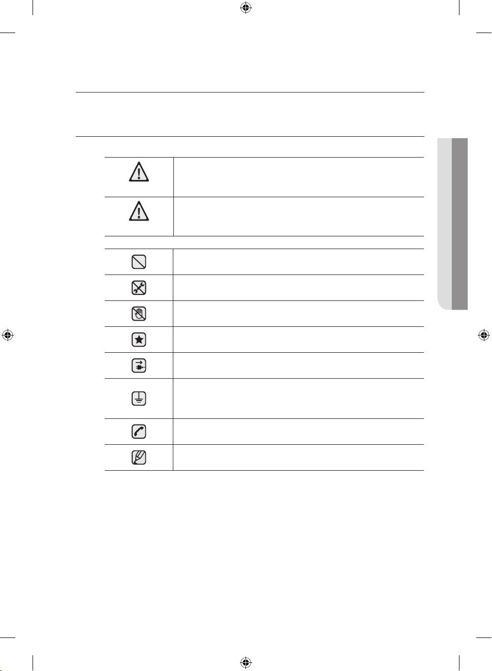
SAFETY SYMBOLS
What the icons and signs in this user manual mean:
You can be killed or seriously injured if you don¡¯t follow
WARNING
CAUTION
instructions.
Minor injury or property damage can result if you don’t follow
instructions.
Do NOT attempt.
Do NOT disassemble.
Do NOT touch.
Follow directions explicitly.
Unplug the power cord from the electrical outlet.
SAFETY INSTRUCTIONS
Make sure the range is plugged into an earth grounded
electrical outlet to prevent electric shock. An outlet equipped
with a Ground Fault Interrupter (GFI) is highly recommended.
Call the service center for help. see page 40
Note
These warning signs are here to prevent injury to you and others.
Please follow them explicitly.
Do not discard this manual. Please keep it in a safe place for future reference
safety instructions _3
Install_NX58F5300SS_DG68-00503A-04_EN.indd 3 3/31/2016 10:19:15 AM
Page 4
IMPORTANT SAFETY
INSTRUCTIONS
WARNING: If the information in this manual is not followed
exactly, a fire or explosion may result causing property
damage, personal injury or death.
– DO NOT store or use gasoline or other flammable vapors
and liquids in the vicinity of this or any other appliance.
– WHAT TO DO IF YOU SMELL GAS:
• DO NOT try to light any appliance.
• DO NOT touch any electrical switch.
• DO NOT use any phone in your building.
• Immediately call your gas supplier from a neighbor’s
phone. Follow the gas supplier’s instructions.
• If you cannot reach your gas supplier, call the fire
department.
– Installation and service must be performed by a qualified
installer, service agency, or the gas supplier.
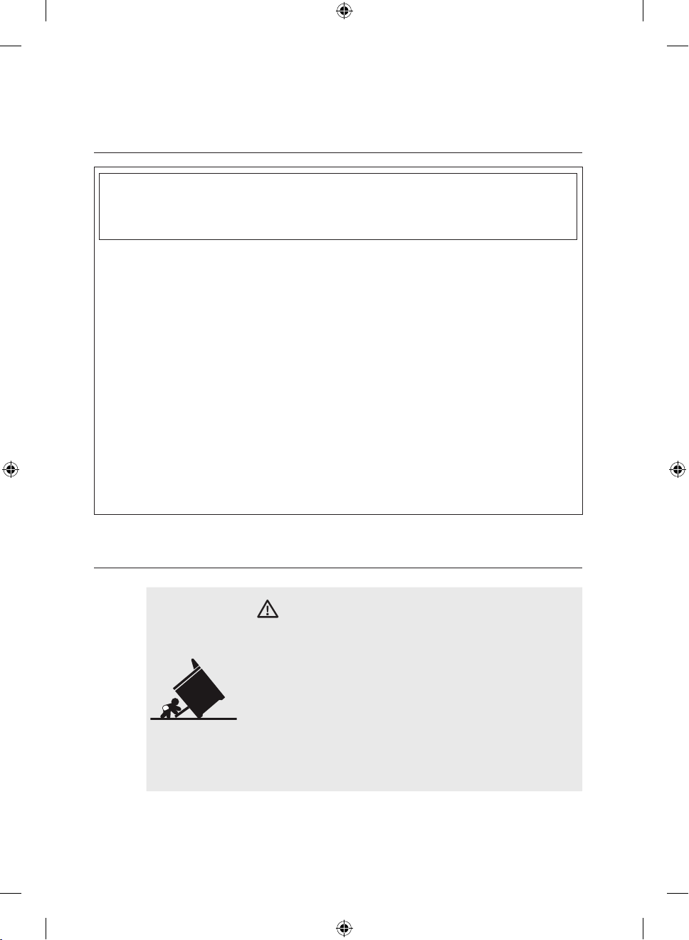
ANTI-TIP DEVICE
WARNING
WARNING
Tip-Over Hazard
• A child or adult can tip the range and be killed.
• Install anti-tip device to range and/or structure
per installation instructions.
• Engage the range to the anti-tip device installed
to the structure.
• Re-engage anti-tip device if range is moved.
• Failure to follow these instructions can result in
death or serious burns to children or adults.
4_ safety instructions
Install_NX58F5300SS_DG68-00503A-04_EN.indd 4 3/31/2016 10:19:15 AM
Page 5
To prevent accidental tipping of the range, attach an approved and packed
anti-tip device to the floor. (See Install the Anti-Tip Device on page 31 in this
manual.) check for proper installation by carefully tipping the range forward.
The anti-tip device should engage and prevent the range from tipping over.
If the range is pulled out away from the wall for any reason, make sure the antitip device is reengaged after the range has been pushed back into place.
Never completely get rid of the leveling legs or the range will not be secured to
the anti-tip device properly.
Follow the installation instructions found on page 32 of this manual. Failure to
follow these instructions can result in death, serious personal injury, and / or
property damage.
DO NOT step / sit / lean on the door or drawer to prevent accidental tipping of
the range.
IMPORTANT SAFETY
PRECAUTIONS
Follow basic precautions when installing and using this range to reduce the risk
WARNING
of fire, electrical shock, injury, or death to persons, including:
Installation and Service
This range must be properly installed and located in accordance with the
installation instructions before it is used.
Professional installation is strongly recommended.
Due to the size and weight of the range, it is highly recommended that two or
more people move or install this appliance.
All ranges can tip over and cause severe injuries. Install the anti-tip device
packed with this range following the instructions found on page 32 in this
manual.
Never try to repair or replace this appliance on your own unless it is specifically
recommended in this manual. This appliance should be serviced only by a
qualified service technician.
Know the location of the gas shut-o valve and how to shut it o if necessary.
Properly remove or destroy the packaging materials after the appliance is
unpacked.
Electrical/Mechanical
SAFETY INSTRUCTIONS
Unplug or disconnect power before servicing.
safety instructions _5
Install_NX58F5300SS_DG68-00503A-04_EN.indd 5 3/31/2016 10:19:15 AM
Page 6
Do not tamper with the controls.
Danger to Children
Do not store any object of interest to children on the cooktop or backguard
of the range. Children climbing on the range to reach items could be killed or
seriously injured.
Keep children away from the door when opening or closing it as they may
bump themselves on the door or catch their fingers in the door.
Keep all packaging materials out of reach of children. Failure to dispose of
plastic bags could result in suocation.
Do not leave children alone or unattended in an area where a range is in use.
They should never be allowed to sit or stand on any part of a range.
Teach children not to touch or play with the controls or any part of the range.
Do not leave the oven door open. An opened door could entice children to
hang on the door or crawl inside the oven. It is recommended to utilize the
control / door lockout feature to reduce the risk of mis-use from children.
Before disposing of the range, cut o the power cord to prevent it being
connected to a power source. Remove the door to prevent children and
animals from getting trapped.
Fire
Do not touch oven burners, drawer burners, or interior surfaces of the oven.
Cooking surfaces, grates, cooktop burners and caps, as well as oven walls
may be hot even though they are dark in color. Interior oven surfaces can
become hot enough to cause burns. During and after use, do not touch or let
clothing or other flammable materials contact oven burners, drawer burners, or
interior surfaces of the oven until they have had sucient time to cool.
Keep oven vent ducts unobstructed. Clean vents frequently to avoid grease
buildup.
Do not let a pot holder touch a hot heating element. Do not use a towel or
other bulky cloth as a pot holder.
Do not use your range to heat unopened food containers or to dry
newspapers.
Keep oven vent ducts unobstructed. Clean vents frequently to avoid grease
buildup.
6_ safety instructions
Install_NX58F5300SS_DG68-00503A-04_EN.indd 6 3/31/2016 10:19:16 AM
Page 7
Never use your range for warming or heating a room. Doing so could result in
carbon monoxide poisoning and/or overheating of the oven.
Loose-fitting or hanging garments should not be worn while using this
appliance.
DO NOT STORE OR USE combustible materials, gasoline, or other flammable
vapors or liquids in the vicinity of this appliance. See “WHAT TO DO IF YOU
SMELL GAS” under the Gas Warnings.
Do not use water on a grease fire. Water might cause a grease fire to explode,
spreading the fire and creating a larger fire and health hazard. Turn o heat
source and smother with tight-fitting lid or use a multipurpose dry chemical or
foam-type fire extinguisher.
Never leave surface units unattended at high heat settings. Boilovers cause
smoking, and greasy spillovers could ignite.
Do not use a flame to check for gas leaks. Use a soapy water mixture around
the area you are checking instead.
Do not place portable appliances, or any other object other than cookware. on
the cooktop. Damage or fire could occur if cooktop is hot.
Do not attempt to operate this appliance if it is damaged, malfunctioning, or
has missing or broken parts.
Never place plastic, paper, or other items that could melt or burn near the oven
vents or any of the surface burners.
If the self-clean mode malfunctions, turn the oven o and disconnect the power
supply. Refer to page 73 and 74 in the User Manual to contact a qualified
service technician.
Steam and Vapors
Use care when opening the oven door. Let hot air or steam escape before
removing or placing food in a hot oven.
Use only dry pot holders. Moist or damp pot holders on hot surfaces may
result in burns from steam.
SAFETY INSTRUCTIONS
safety instructions _7
Install_NX58F5300SS_DG68-00503A-04_EN.indd 7 3/31/2016 10:19:16 AM
Page 8
GAS WARNINGS
If the information in this manual is not followed exactly, a fire or explosion may
WARNING
result, causing death, personal injury, or property damage.
1. DO NOT light a match, candle, or cigarette.
2. DO NOT turn on any gas or electric appliances.
3. DO NOT touch any electrical switches.
4. DO NOT use any phone in your building.
5. Clear the room, building, or area of all occupants.
6. Immediately call your gas supplier from a neighbor’s phone. Follow the gas
supplier’s instructions.
7. If you cannot reach your gas supplier, call the fire department.
Read instructions completely and carefully.
Installation of this range must conform with local codes or, in the absence of
local codes, with the National Fuel Gas Code, ANSI Z223.1/NFPA.54, latest
edition. In Canada, installation must conform with the current Natural Gas
Installation Code, CAN/CGA-B149.1, or the current Propane Installation Code,
CAN/CGA-B149.2, and with local codes where applicable. This range has
been design-certified by ETL according to ANSI Z21.1, latest edition, and
Canadian Gas Association according to CAN/CGA-1.1, latest edition.
Installation and service must be performed by a qualified installer, service
agency, or gas supplier.
Have the installer show you the location of the gas shut-o valve and how to
shut it o.
Always use NEW flexible connectors when installing a gas appliance. Never
reuse old flexible connectors. The use of old flexible connectors can cause gas
leaks and personal injury.
Never use this appliance as a space heater to heat or warm the room. Doing
so may result in carbon monoxide poisoning and overheating of the oven.
Never block the oven vents (air openings). They provide the air inlet and
exhaust that are necessary for the oven to operate properly with correct
combustion.
8_ safety instructions
Install_NX58F5300SS_DG68-00503A-04_EN.indd 8 3/31/2016 10:19:16 AM
Page 9
STATE OF CALIFORNIA
PROPOSITION 65 WARNING
(US ONLY)
WARNING : This product contains chemicals known to the State of California
to cause cancer and birth defects or other reproductive harm.
Gas appliances can cause low-level exposure to Proposition 65 listed
substances, including but not limited to, benzene, carbon monoxide,
formaldehyde and soot, substances resulting from the incomplete combustion
of natural gas or LP fuels.
IN THE COMMONWEALTH OF
MASSACHUSETTS
This product must be installed by a qualified plumber or gas fitter by the State
of Massachusetts.
When using ball-type gas shut-o valves, they shall be the T-handle type.
Multiple flexible gas lines must not be connected in series.
SAFETY INSTRUCTIONS
safety instructions _9
Install_NX58F5300SS_DG68-00503A-04_EN.indd 9 3/31/2016 10:19:16 AM
Page 10
WARNING
ELECTRICAL WARNINGS
Comply with the following electrical instructions and requirements to avoid
death, personal injury from electric shock, and/or property damage from fire:
1. Plug into a grounded 3-prong outlet.
2. DO NOT remove ground prong.
3. DO NOT use an adapter.
4. NEVER use an extension cord.
Use a dedicated 120-volt, 60-Hz, 20-amp, AC, fused electrical circuit for this
appliance. A time-delay fuse or circuit breaker is recommended. DO NOT plug
more than one appliance in this circuit.
The range is supplied with a 3-prong grounded plug. This cord MUST be
plugged into a mating, grounded 3-prong outlet that meets all local codes and
ordinances. If you are unsure your electrical outlet is properly grounded, have it
checked by a licensed electrician.
If codes permit the use of a separate ground wire, it is recommended that a
qualified electrician determine the proper path for this ground wire.
Electrical service to the range must conform to local codes. Barring local
codes, it should meet the latest ANSI/NFPA No. 70 – Latest Revision (for the
U.S.) or the Canadian Electrical Code CSA C22.1 – Latest Revisions.
It is the personal responsibility of the appliance owner to provide the correct
electrical service for this appliance.
NEVER connect ground wire to plastic plumbing lines, gas lines, or hot water
pipes.
DO NOT modify the plug provided with the appliance.
DO NOT have fuse in a neutral or ground circuit.
10_ safety instructions
Install_NX58F5300SS_DG68-00503A-04_EN.indd 10 3/31/2016 10:19:16 AM
Page 11
GROUNDING INSTRUCTIONS
Grounding a range with a cord connection:
This appliance must be Earth grounded. In the event of a malfunction or
breakdown, grounding will reduce the risk of electrical shock by providing a
path for the electric current. This appliance is equipped with a cord having a
grounding plug. The plug must be firmly plugged into an outlet that is properly
installed and grounded in accordance with the local codes and ordinances.
Improper connection of the grounding plug can result in a risk of electric
WARNING
shock. Check with a qualified electrician if you have any doubt the appliance is
properly grounded.
NEVER modify the plug provided with the appliance. If it does not fit the
existing outlet, have a qualified electrician install a proper outlet.
INSTALLATION WARNINGS
Have your range installed and properly grounded by a qualified installer, in
accordance with the grounding instructions on page 25. Any adjustment and
service should be performed only by qualified gas range installers or service
technicians.
Be sure your range is correctly installed and adjusted by a qualified service
technician or installer for the type of gas (natural or LP) that is to be used. To
utilize LP fuel source, the 5 surface burner orifices, 2 oven orifices must be
exchanged with the provided LP orifice set, and the GPR adapter must be
reversed.
These adjustments must be made by a qualified service technician
WARNING
in accordance with the manufacturers instructions and all codes and
requirements of the authority having jurisdiction. Failure to follow these
instructions could result in serious injury or property damage. The qualified
agency performing this work assumes responsibility for the conversion.
Do not attempt to repair or replace any part of your range unless it is
specifically recommended in this manual. All other service should be referred to
a qualified technician.
This appliance must be properly grounded. Plug your range into a 120volt grounded outlet that is only used for this appliance. Do not remove the
grounding (third) prong from the plug. Firmly plug the power cord into the wall
outlet. If you are not sure your electrical outlet is grounded, it is your personal
responsibility and obligation to have a properly grounded, three-prong outlet
installed in accordance with local and national codes. Do not use a damaged
power plug or loose wall outlet. Do not use an extension cord with this
appliance. In addition, do not use an adapter or otherwise defeat the grounding
plug. If you do not have a proper outlet or have any doubt, consult a licensed
electrician.
SAFETY INSTRUCTIONS
safety instructions _11
Install_NX58F5300SS_DG68-00503A-04_EN.indd 11 3/31/2016 10:19:16 AM
Page 12
Locate the range out of kitchen trac paths and drafty locations to prevent
poor air circulation.
This appliance should be positioned in such a way that the power plug is
accessible.
Do not install in an area exposed to dripping water or outside weather
conditions.
Remove all packaging materials from the range before operating it. These
materials can ignite, causing smoke and/or fire damage.
Install this appliance on a level and hard floor that can support its weight.
Synthetic flooring, like linoleum, must withstand 180 °F (82 °C) temperatures
without shrinking, warping, or discoloring. Never install the range directly
over interior kitchen carpeting unless a sheet of 0.25-inch plywood or similar
insulator is placed between the range and carpeting.
Never block the vents (air openings) of the range. They provide the air inlet and
exhaust necessary for the range to operate properly with correct combustion.
Air openings are located behind the range, under the oven control panel, at
the top and bottom of the oven door, and under the lower warming or storage
drawer.
Large scratches or impacts on door glass can cause the glass to break or
shatter.
Make sure the wall coverings around the range can withstand heat, up to 200
°F (93 °C), generated by the range.
Avoid placing cabinets above the range. This reduces the hazard caused by
reaching over the open flames of operating burners.
If cabinets are placed above the range, allow a minimum clearance of 40
in (102 cm) between the cooking surface and the bottom of unprotected
cabinets.
Install a ventilation hood or an externally vented Over The Range Microwave
Oven over the range cooktop that is as wide as the range, centered over the
range, and projects forward beyond the front of the cabinets. See page 21 in
this manual.
Remove all tape and packaging. Make sure the burners are properly seated
and level.
Remove any accessories from the oven and/or lower drawer.
Check to make sure no range parts have come loose during shipping.
Seal any openings in the wall behind the appliance and in the floor under the
appliance after the gas supply line is installed.
12_ safety instructions
Install_NX58F5300SS_DG68-00503A-04_EN.indd 12 3/31/2016 10:19:16 AM
Page 13
SURFACE BURNER WARNINGS
Follow basic precautions when installing and using this range to reduce the risk
WARNING
of fire, electrical shock, injury, or death to persons, including.
Use proper pan sizes. Avoid pans that are unstable or warped. Select
cookware having flat bottoms large enough to cover the burner grates. To
avoid spillovers, make sure cookware is large enough to contain your food.
This will save cleaning time and prevent hazardous accumulations of food,
since heavy spattering or spillovers left on the range can ignite. Use pans with
handles that can be easily grasped and remain cool.
Always use the LITE position when igniting the top burners. Make sure the
burners have ignited.
Never leave the surface burners unattended at HIGH flame settings. Boilovers
cause smoking, and greasy spillovers that might catch on fire.
Adjust the top burner flame size so it does not extend beyond the edge of the
cookware. Excessive flames past cookware edges can be hazardous.
Only use dry pot holders. Pot holders with moisture in them may result in burns
from steam when they come in contact with hot surfaces.
Keep pot holders away from open flames when lifting cookware. Never use a
towel or bulky cloth in place of a pot holder.
Keep all plastic away from the surface burners or any open flame.
When using glass cookware, make sure it is designed for top-of-range
cooking.
Always make sure cookware handles are turned to the side or rear of the
cooktop, but not over other surface burners. This will minimize the chance of
burns, spillovers, and ignition of flammable materials due to bumping the pan.
Do not wear loose or hanging garments when using the range. They could
ignite and burn you if they touch a surface burner.
Always heat frying oils slowly, and watch as it heats. If foods are being fried
at high heat, carefully watch during the cooking process. If a combination of
fats or oils are to be used during frying, they need to be stirred together before
heating.
SAFETY INSTRUCTIONS
safety instructions _13
Install_NX58F5300SS_DG68-00503A-04_EN.indd 13 3/31/2016 10:19:16 AM
Page 14
Use a deep fryer thermometer whenever possible. This prevents overheating
fryer beyond the smoking point.
Use as little fryer as possible for shallow or deep-fat frying. Using too much fat
can cause spillovers when food is added.
Items should always be removed from the cooktop when they are done
cooking. Never leave plastic items on the cooktop. This prevents the hot air
from the vent from igniting flammable items, melting, or building up pressure in
closed containers.
This cooktop is not designed to flame foods or cooking with a wok or wok ring
attachment. If foods are flamed, they should only be flamed under a ventilation
hood that is on.
Always make sure foods being fried are thawed and dried. Moisture of any kind
can cause hot fat to bubble up and over the sides of the pan.
Never move a pan or deep-fat fryer full of hot fat. It should always be cooled
before moving.
Always make sure the controls are OFF and the grates are cool before they are
removed to prevent any possibility of burning.
If range is located near a window, NEVER hang long curtains or paper blinds
on that window. They could blow over the surface burners and ignite, causing
a fire hazard.
Grease is flammable and should be handled very carefully. Do not use water on
grease fires.
If you smell gas, turn o the gas to the range and call a qualified service
technician. NEVER use an open flame to locate a leak.
Always turn o the surface burner controls before removing cookware. All
surface burner controls should be turned OFF when not cooking.
Do not use a wok on the cooking surface if the wok has a round metal ring that
is placed over the burner grate to support the wok. This ring acts as a heat
trap, which may damage the burner grate and burner head. Also, it causes the
burner to work improperly. This may cause a carbon monoxide level above that
allowed by current standards, resulting in a health hazard.
14_ safety instructions
Install_NX58F5300SS_DG68-00503A-04_EN.indd 14 3/31/2016 10:19:16 AM
Page 15
OVEN WARNINGS
NEVER cover any holes or passages in the bottom oven cover. NEVER
WARNING
cover an entire oven rack with aluminum foil or like material. Covering bottom
cover and/or racks blocks airflow through the oven and could cause carbon
monoxide poisoning.
Do not use aluminum foil or foil liners anywhere in the oven, Misuse traps heat
and could cause a fire hazard or damage the range.
Always follow the manufacturers directions when using cooking or roasting
bags in the oven.
DO NOT clean the door gasket. The door gasket is essential for a good seal.
Care should be taken not to damage or move the gasket.
Stand away from the range when opening the door of a hot oven. The
escaping hot air and steam can cause burns to hands, face and eyes.
Do not use the oven for storage. Stored items can be damaged or ignite.
Keep the oven free from grease buildup.
Reposition oven racks when the oven is cool to prevent burning or personal
injury.
Do not heat unopened containers. pressure in the container could build up,
resulting in explosion and/or personal injury.
Only use glass cookware that is recommended for use in gas ovens.
Always remove broiler pan from range when the broiling is finished. Clean after
each use. This prevents fire flare-ups from stored grease buildup.
Do not broil meat too close to the burner flame. Trim excess fat from meat
before cooking. Meat fat can ignite, causing a fire hazard. Make sure broiler
pan is placed correctly to reduce the possibility of grease fires.
If a grease fire should occur in the oven, turn o the oven by pressing the
Clear/O pad. Keep the oven door closed to put out the fire.
Always bake and/or broil with the oven door closed. Broiling with the door
partially or fully open can damage the surface burner control knobs.
Keep the appliance area clear and free from combustible materials, gasoline,
and other flammable vapors and liquids.
Do not use the oven to dry newspapers or mail. Such items will catch fire if
overheated.
For safety and proper cooking performance, always bake and broil with the
oven door closed.
SAFETY INSTRUCTIONS
safety instructions _15
Install_NX58F5300SS_DG68-00503A-04_EN.indd 15 3/31/2016 10:19:16 AM
Page 16
ELECTRIC WARMING DRAWER
OR LOWER STORAGE DRAWER
WARNINGS
The warming drawer is designed to keep hot cooked foods at a serving
temperature. Always start with hot food. Cold or room-temperature foods
cannot be heated, warmed, or cooked in the warming drawer.
Do not touch the interior drawer surface or heating element. These surfaces
may be hot and could burn you.
Use care when opening the drawer. Escaping hot air and/or steam can cause
burns or personal injury.
Do not use aluminum foil to line the lower drawer. Aluminum foil will trap heat
and alter the warming performance of the drawer. It could also damage the
interior finish.
Never use or self-clean the oven drawer pan in the upper oven.
Never leave jars or cans of fat drippings in or near your drawer.
Do not leave or store paper products, plastics, canned food, or combustible
materials in the drawer. Do not use drawer to dry newspapers. They could
ignite or melt if overheated.
Do not use the drawer to dry newspapers. If overheated, they can catch on
fire.
16_ safety instructions
Install_NX58F5300SS_DG68-00503A-04_EN.indd 16 3/31/2016 10:19:16 AM
Page 17
SELF-CLEANING OVEN WARNINGS
Follow basic precautions when installing and using this range to reduce the risk
WARNING
of fire, electrical shock, injury, or death to persons, including:
Do not leave children unattended near the range during a self-cleaning cycle.
The outside surfaces of the range get hot enough to burn if touched.
Stand away from the range when opening the oven door after a self-cleaning
cycle. The oven will be VERY HOT and the escaping hot air and steam can
cause burns.
Remove all racks and other utensils from the oven before starting a self clean
cycle. The oven racks may become damaged, and foreign objects could ignite
if left within the oven cavity.
Wipe o any excess spillage before using the self-cleaning operation.
Remove any broiler pans, all cookware, oven probe, and any aluminum foil
before using the self-cleaning operation.
Never self-clean with the lower drawer or drawer pan placed in the oven.
If the self-cleaning operation malfunctions, turn o the oven, disconnect the
power supply, and contact a qualified service technician.
Do not use oven cleaners. Commercial oven cleaners or oven liners should
NEVER be used in or around any part of the oven. Residue from oven cleaners
will damage the inside of the oven during a self-cleaning operation.
Nickel oven shelves should be removed from the oven during a self-cleaning
cycle. Porcelain-coated oven shelves may be cleaned in the oven during a selfcleaning cycle.
Do not clean the door gasket. The door gasket is essential for a good seal.
Care should be taken not to rub, damage, or move the gasket.
SAFETY INSTRUCTIONS
PROPER COOKING OF MEAT AND
POULTRY
Make sure all meat and poultry is cooked thoroughly. Meat should always be
cooked to an internal temperature of 160 °F (71 °C). Poultry should always be
cooked to an internal temperature of 180 °F (82 °C). Cooking these foods to
these minimally safe temperatures can help protect you and your family from
foodbourne illnesses.
safety instructions _17
Install_NX58F5300SS_DG68-00503A-04_EN.indd 17 3/31/2016 10:19:16 AM
Page 18
contents
GAS RANGE COMPONENTS
19
INSTALLATION
REQUIREMENTS
21
TOOLS AND MATERIALS
27
INSTALLATION
INSTRUCTIONS
28
19 Overview
20 Gas range specifications
21 Location requirements
23 Gas requirements
24 Special gas requirements (gas models
sold in massachusetts)
24 Electrical requirements
27 What’s in the box
28 Installing your gas range
28 Step 1. Unpack the range
28 Step 2. Connect the range to gas
supply
30 Step 3. Convert to lp gas (optional)
31 Step 4. Install the anti-tip device
32 Step 5. Plug in and place
32 Step 6. Level the range
33 Step 7. Assemble the surface burners
34 Step 8. Check the ignition of surface
burners and oven burners
36 Step 9. Final installation checklist
37 Adjusting the oven burner air
adjustment shutters
18_ contents
Install_NX58F5300SS_DG68-00503A-04_EN.indd 18 3/31/2016 10:19:17 AM
Page 19
gas range components
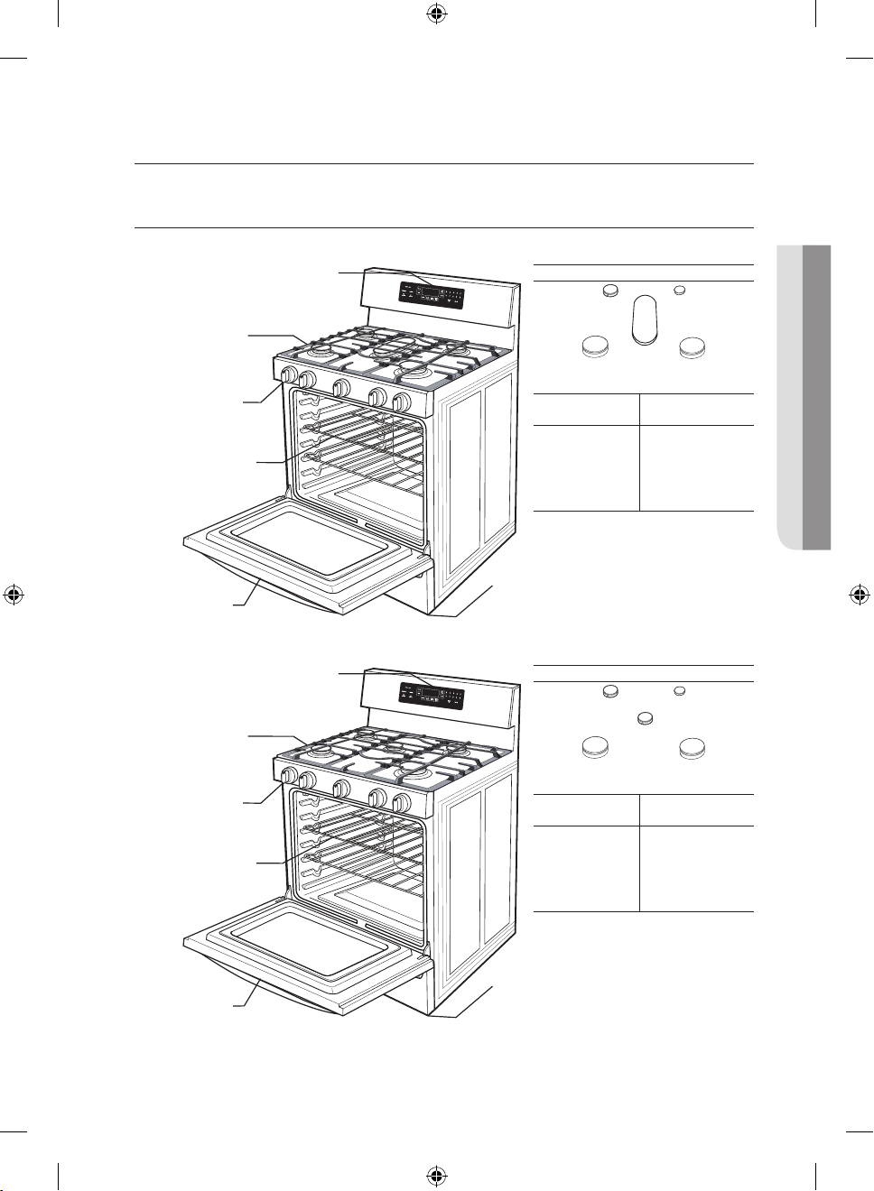
OVERVIEW
MODEL NX58F5500SS, NX58F5500SB, NX58F5500SW
Control Panel And Digital
Display
Heavy-Duty
continous cast
Grates
Cooktop Burner
Knobs
Oven Racks (2)
Oven Door
MODEL NX58F5300SS
Control Panel And Digital
Display
Heavy-Duty
continous cast
Grates
Cooktop Burner
Knobs
Oven Racks (2)
GAS RANGE COMPONENTS
Cooktop Burner Placement
Cooktop Burners (under grates)
Burner Locations and Output Ratings
Location Output Rating
(Natural Gas)
Left-Front (LF) 12,000 BTU
Left-Rear (LR) 9,500 BTU
Center (CTR) 9,500 BTU
Right-Rear (RR) 5,000 BTU
Right-Front (RF) 17,000 BTU
Storage Drawer
Cooktop Burner Placement
Cooktop Burners (under grates)
Burner Locations and Output Ratings
Location Output Rating
(Natural Gas)
Left-Front (LF) 12,000 BTU
Left-Rear (LR) 9,500 BTU
Center (CTR) 9,500 BTU
Right-Rear (RR) 5,000 BTU
Right-Front (RF) 16,000 BTU
Storage Drawer
Oven Door
gas range components _19
Install_NX58F5300SS_DG68-00503A-04_EN.indd 19 3/31/2016 10:19:17 AM
Page 20
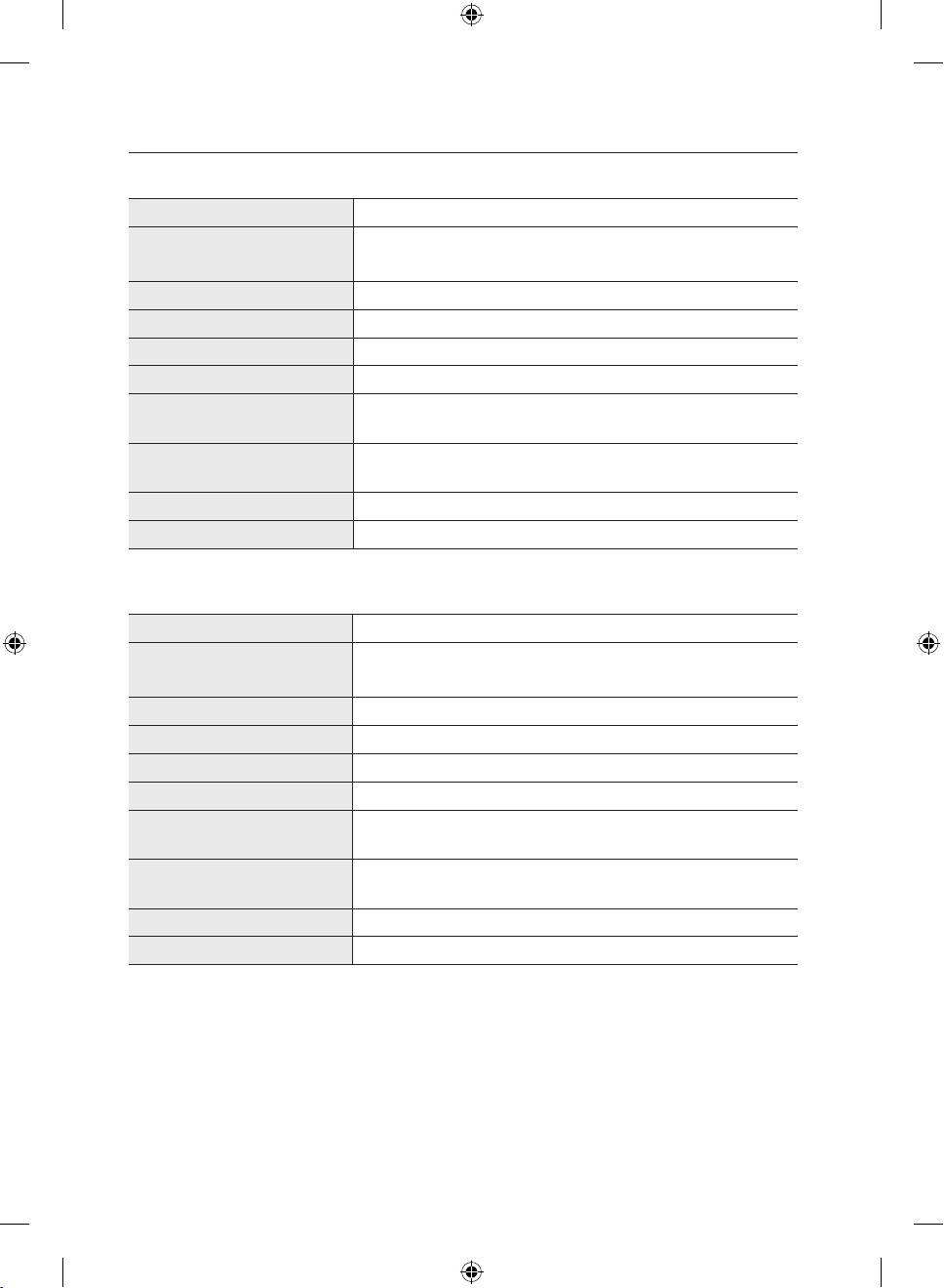
GAS RANGE SPECIFICATIONS
MODEL NX58F5500SS, NX58F5500SB, NX58F5500SW
DESCRIPTION Gas Free-Standing Range
13
/
OVERALL DIMENSIONS 29
in (W) x 45 25/
16
757 mm (W) x 1163 mm (H) x 602 mm (D)
NET WEIGHT 187 lb (85 kg)
ELECTRICAL Refer to the rating label.
GAS, NG (NATURAL GAS) 5–13 in WC
GAS, LP (LIQUID PROPANE) 10–13 in WC
SURFACE BURNERS (NG) (LF)–12,000 BTU / (LR)–9,500 BTU / (CTR)–9,500 BTU /
(RR)–5,000 BTU / (RF)–17,000 BTU
SURFACE BURNERS (LP) (LF)–10,000 BTU / (LR)–7,500 BTU / (CTR)–7,500 BTU /
(RR)–4,000 BTU / (RF)–12,500 BTU
OVEN BURNERS (NG) Broil (Upper)–13,500 BTU / Bake (Lower)–18,000 BTU
OVEN BURNERS (LP) Broil (Upper)–11,500 BTU / Bake (Lower)–15,000 BTU
MODEL NX58F5300SS
DESCRIPTION Gas Free-Standing Range
13
/
OVERALL DIMENSIONS 29
in (W) x 45 25/
16
757 mm (W) x 1163 mm (H) x 602 mm (D)
NET WEIGHT 187 lb (85 kg)
ELECTRICAL Refer to the rating label.
GAS, NG (NATURAL GAS) 5–13 in WC
GAS, LP (LIQUID PROPANE) 10–13 in WC
SURFACE BURNERS (NG) (LF)–12,000 BTU / (LR)–9,500 BTU / (CTR)–9,500 BTU /
(RR)–5,000 BTU / (RF)–16,000 BTU
SURFACE BURNERS (LP) (LF)–10,000 BTU / (LR)–7,500 BTU / (CTR)–7,500 BTU /
(RR)–4,000 BTU / (RF)–12,500 BTU
OVEN BURNERS (NG) Broil (Upper)–13,500 BTU / Bake (Lower)–18,000 BTU
OVEN BURNERS (LP) Broil (Upper)–11,500 BTU / Bake (Lower)–15,000 BTU
in (H) x 23 11/
32
in (H) x 23 11/
32
16
in (D)
16
in (D)
20_ gas range components
Install_NX58F5300SS_DG68-00503A-04_EN.indd 20 3/31/2016 10:19:18 AM
Page 21
installation requirements
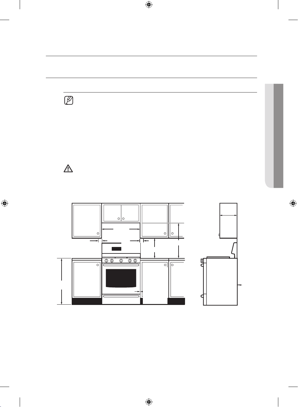
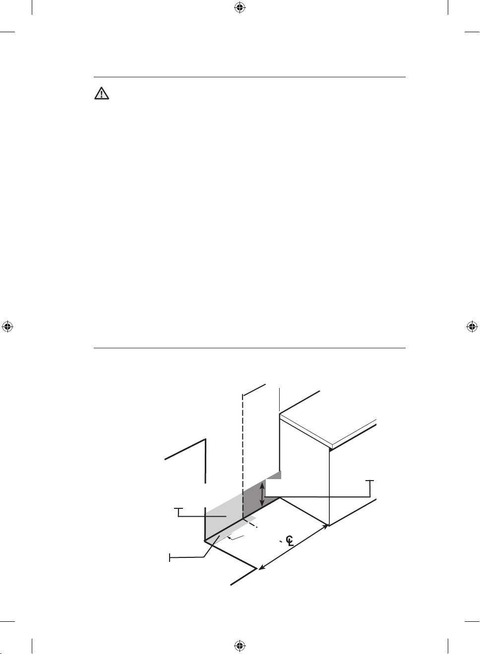
LOCATION REQUIREMENTS
Clearances and dimensions
For OTR over Gas Stove, please follow local GAS CODE.
BEFORE YOU BEGIN to install this appliance, refer to the following information,
dimensions, and clearances. Do not locate the range where it may be
subject to strong drafts. Provide adequate clearances between the range and
adjacent combustible surfaces. These dimensions must be met for safe use of
the range. The location of the electrical outlet and gas piping may be adjusted to
meet the following dimensions and clearances.
For installation in Canada, a free-standing range is not to be installed
closer than 4.7 in (12 cm) from any adjacent surface.
This range has been designed to comply with the maximum allowable
wood cabinet temperature of 194 °F (90 °C). Make sure the wall covering,
CAUTION
countertops, and cabinets around the range can withstand the heat (up to
194 °F [90 °C]) generated by the range. If not, discoloration, delamination, or
melting may occur.
13 in (33 cm)
Overhead
Side
Clearance
Above
Cooking
Surface to
Wall
4 in
(10.2 cm)
30 in
(15.2 cm)
6 in
30 in (76.2 cm)
18 in (45.7 cm)
Cabinet
Depth
INSTALLATION REQUIREMENTS
0 in (0 cm)
Clearance
Below
Cooking Top
and at Rear
and Sides of
Range
0 in
(15.2 cm)
36 in
(91.4 cm)
24 in
(61 cm)
Lower
Cabinet
Depth
installation requirements _21
Install_NX58F5300SS_DG68-00503A-04_EN.indd 21 3/31/2016 10:19:18 AM
Page 22
Minimum dimensions
If overhead cabinets are provided, a range hood should also be provided
that projects horizontally a minimum of 5 in (12.7 cm) beyond the front of
WARNING
the cabinets. This will dissipate any heat buildup in the overhead cabinets
to prevent death, personal injury, and/or fire hazard. The ventilating hood
must be constructed of sheet metal not less then 0.0122" thick. Install
above the cooktop with a clearance of not less than 1/4" between the hood
and the underside of the combustible material or metal cabinet. The hood
must be at least as wide as the appliance and centered over the appliance.
Clearance between the cooking surface and the ventilation hood surface
must never be less than 24 inches.
Exception :
Installation of a listed microwave oven or cooking appliance over
the cooktop shall conform to the installations packed with that appliance.
• 30-in (101.6-cm) minimum clearance between the top of the cooking
surface and the bottom of an unprotected wood or metal cabinet; or If no
30-in(101.6-cm) minimum clearance, 24-in (61-cm) minimum when the
bottom of the wood or metal cabinet is protected by not less than 0.25-in
(0.64-cm) flame-retardant millboard covered with not less than no. 28
MSG sheet steel, 0.015-in (0.038-cm) stainless steel, 0.024-in (0.061cm) aluminum, or 0.020-in (0.051-cm) copper.
• 18-in (45.7-cm) minimum between the countertop and the adjacent
cabinet bottom.
Recommended locations for gas piping and electrical
outlets
(For models FX710BGS, FX510BGS, and NX583G0VBSR / NX583G0VBBB /
NX583G0VBWW)
Recommended area for
120 V electrical outlet
on rear wall
(43.2 cm x 22.9 cm)
Gas Wall Area
Recommended area
for through-the-wall
and through-the-floor
connection of gas pipe
stub and shut-o valve.
17 in x 9 in
12 in
(30.5 cm)
17 in x 2 in
(43.2 cm x 5.1 cm)
Gas Floor Area
30 in (76.2 cm)
Cabinet Opening
22_ installation requirements
Install_NX58F5300SS_DG68-00503A-04_EN.indd 22 3/31/2016 10:19:19 AM
Page 23
GAS REQUIREMENTS
Provide adequate gas supply
This range is designed to operate at a pressure of 5 in (13 cm) of water
column on natural gas or 10 in (25 cm) of water column on LP gas
(propane or butane).
Make sure you are supplying your range with the type of gas for which it is
designed. Do not attempt to convert the appliance from the gas specified
in this manual to a dierent gas without consulting the gas supplier.
This range is convertible for use on natural or propane gas. If you decide to use
this range on LP gas, conversion must be made by a qualified LP installer before
attempting to operate the range.
For proper operation, the pressure of natural gas supplied to the regulator must
be between 5 in and 13 in (13 cm and 33 cm) of water column.
For LP gas, the pressure supplied must be between 10 in and 13 in (25 cm and
33 cm) of water column.
When checking for proper operation of the regulator, the inlet pressure must be
at least 1 in (2.5 cm) greater than the operating (manifold) pressure as given.
The pressure regulator located at the inlet of the range manifold must remain in
the supply line regardless of whether natural or LP gas is being used.
A flexible-metal appliance connector used to connect the range to the gas
supply line should have an I.D. of 0.5 in (1.3 cm) and be 5 ft (152 cm) in length
for ease of installation. In Canada, flexible connectors must be single-wall metal
connectors no longer than 6 ft (183 cm) in length.
Do not kink or damage the flexible metal tubing when moving the range.
INSTALLATION REQUIREMENTS
installation requirements _23
Install_NX58F5300SS_DG68-00503A-04_EN.indd 23 3/31/2016 10:19:19 AM
Page 24
SPECIAL GAS REQUIREMENTS (GAS MODELS SOLD IN
MASSACHUSETTS)
COMMONWEALTH OF MASSACHUSETTS REQUIREMENTS:
Gas leaks may occur in your system, creating a dangerous situation.
WARNING
– Gas leaks may not be detected by smell alone.
– Gas suppliers recommend you purchase and install a UL-approved
gas detector. Gas detector should be installed in accordance with the
manufacturers instructions.
• Range must be installed by a qualified plumber or gas fitter by the State of
Massachusetts.
• A T-handle manual gas valve MUST be installed in the gas supply line to your
range.
• If a flexible gas connector is used to install your range, multiple flexible gas lines
must not be connected in series.
ELECTRICAL REQUIREMENTS
To reduce the risk of fire, electric shock, or personal injury:
WARNING
All ranges
• Do not use an extension cord or adapter plug with this range.
• This range must be properly grounded.
• Check with a qualified electrician if you are in doubt as to whether your range
is properly grounded.
• Do not modify the plug provided with your range—if it doesn¡¯t fit the outlet,
have a proper outlet installed by a qualified electrician.
• All wiring and grounding must be done in accordance with local codes or, in
the absence of local codes, with the National Electrical Code, ANSI/NFPA No.
70 – Latest Revision (for the U.S.) or the Canadian Electrical Code CSA C22.1
– Latest Revisions and local codes and ordinances.
• Wiring diagram is located on the back of the range. (Inside of the cover back
wire)
• This range is equipped with an electronic ignition system that will not operate
if plugged into an outlet that is not properly polarized.
24_ installation requirements
Install_NX58F5300SS_DG68-00503A-04_EN.indd 24 3/31/2016 10:19:19 AM
Page 25

Gas models
• All gas models are equipped with a power cord with an equipment-grounding
conductor and a grounding plug.
• A 120-Volt, 60-Hz, AC, approved electrical service with or 20-amp circuit
breaker or time-delay fuse is required for all U.S. and Canadian models.
• Check for ¾-in (1.9-cm) UL-listed strain relief where the power cord comes
out of the range cabinet.
• Do not reuse a power supply cord from an old range or other appliance.
• The power cord electric supply wiring must be retained at the range cabinet
with a suitable UL-listed strain relief.
• A time-delay fuse or circuit breaker is also recommended.
Grounding
• All ranges must be grounded for personal safety.
• All gas models have a power cord with an equipment-
grounding conductor
and a grounding plug.
• The plug must be firmly plugged into a three-prong outlet
that is properly installed and grounded in accordance with
all local codes and ordinances. In the event of a malfunction
or breakdown, grounding will increase the risk of electrical
shock by not providing a path for the electric current.
• Do not use a damaged power plug or loose wall outlet.
• Do not use an extension cord or adapter with this appliance.
• Do not, under any circumstances, cut, modify, remove, or otherwise defeat
the grounding (third) prong from the power cord. If the plug and the outlet
do not match or you have any doubt, have a qualified electrician install the
proper outlet.
The customer should have the wall receptacle and circle checked by a
qualified electrician to make sure the receptacle is properly grounded.
Ground Fault Circuit Interrupters(GFCIs) are not required ot recommended for
gas range receptacles.
• NEVER connect ground wire to plastic plumbing lines, gas lines, or water
pipes.
Failure to follow these instructions can result in death, fire, or electrical
shock.
CAUTION
Ensure proper
ground
and firm
connection
before use.
INSTALLATION REQUIREMENTS
installation requirements _25
Install_NX58F5300SS_DG68-00503A-04_EN.indd 25 3/31/2016 10:19:19 AM
Page 26

Usage situations where appliance power cord will be
disconnected frequently
Do not use an adapter plug in these situations because disconnecting of the
power cord places undue strain on the adapter and leads to eventual failure
of the adapter ground terminal. Where a standard two-prong wall receptacle
is encountered, it is the personal responsibility and obligation of the customer
to have it replaced with a three-prong (grounding) receptacle by a qualified
electrician before using the appliance.
Additional installation requirements for mobile homes
The installation of appliances designed for mobile home installation must conform
with the Manufactured Home Construction and Safety Standard, Title 24 CFR,
Part 3280 (formerly the Federal Standard for Mobile Home Construction and
Safety, Title 24, HUD, Part 280) or, when such standard is not applicable, the
Standard for Manufactured Home Installations, latest edition (Manufactured
Home Sites, Communities and Set-Ups), ANSI A225.1, latest edition, or with
local codes. In Canada, mobile home installation must be in accordance with the
current CAN/CSA Z240/MH Mobile Home Installation Code.
Power cord location
The power cord for this appliance is located
on the back of the range, near the bottom right
hand corner. The 53-in (135-cm) power cord will
come installed on the range and taped to the
back for shipping.
Power cord location
26_ installation requirements
Install_NX58F5300SS_DG68-00503A-04_EN.indd 26 3/31/2016 10:19:19 AM
Page 27

tools and materials
WHAT’S IN THE BOX
Parts supplied
Surface burners and caps (5)
(Model NX58F5500SS/
NX58F5500SB/NX58F5500SW)
Oven racks (2)
Griddle
(Model NX58F5500SS/
NX58F5500SB/NX58F5500SW)
• Make sure you have received all of the supplied parts shown above.
• If your range was damaged during shipping or you do not have all of the
supplied parts, contact your local retailer.
Surface burners and caps (5)
(Model NX58F5300SS)
Oven racks (2)
(Model NX58F5300SS)
Surface burner grates (3)
Anti-tip bracket kit
Parts needed
Gas line
shut-o
valve
Flexible metal
appliance
connector ½ in (ID)
x 5 ft
Flare union
adapter ¾ in or
½ in (NPT) x ½
in (ID)
Flare union
adapter ½ in
(NPT) x ½ in (ID)
135-degree
elbow
(optional)
Lag bolt
or ½-in
(OD) sleeve
anchor
TOOLS AND MATERIALS
Tools needed
Flat-blade
screwdriver
Pencil and
ruler
Install_NX58F5300SS_DG68-00503A-04_EN.indd 27 3/31/2016 10:19:23 AM
Phillips
screwdriver
Level Pipe joint compound Utility knife
Open-end or adjustable
wrench
Pipe wrench (2) Nut driver
tools and materials _27
Soapy water
solution
Page 28

installation instructions
INSTALLING YOUR GAS RANGE
IMPORTANT: Please read the following instructions, as well as the Important Safety
Instructions section at the front of this manual, completely and carefully BEFORE
installing and/or operating the gas range. Improper installation, adjustment, service, or
maintenance can cause personal injury or property damage.
To order parts or accessories, contact your
local retailer or refer to the last page.
To ensure proper installation, we strongly
recommend that you hire a professional
installer.
Step 1. Unpack the range
Remove all packaging materials. Failure to remove packaging materials could
result in damage to the appliance.
Inventory all loose parts against the Parts supplied components listed on page 27.
Check for shipping damage and/or missing parts. Any damage and/or missing
parts should be reported to your local retailer.
Step 2. Connect the range to gas supply
Shut o the main gas supply valve before disconnecting the old range and
leave it o until the new hookup has been completed. Don’t forget to relight
the pilot on other gas appliances when you turn the gas back on.
Because hard piping restricts movement of the range, the use of a CSA
International-certified flexible metal appliance connector is recommended unless
local codes require a hard-piped connection.
28_ installation instructions
Install_NX58F5300SS_DG68-00503A-04_EN.indd 28 3/31/2016 10:19:23 AM
Page 29

If the information in this manual is not followed exactly, a fire or explosion
may result, causing death, personal injury, or property damage.
WARNING
– Do not store or use gasoline or other flammable vapors and liquids in the
vicinity of this or any other appliance.
– WHAT TO DO IF YOU SMELL GAS:
• DO NOT light a match, candle, or cigarette.
• DO NOT try to light any appliance.
• DO NOT touch any electrical switch.
• DO NOT use any phone in your building.
• Clear the room, building, or area of all occupants.
• Immediately call your gas supplier from a neighbor’s phone. Follow the
gas supplier’s instructions.
• If you cannot reach your gas supplier, call the fire department.
– Installation and service must be performed by a qualified installer, service
agency, or gas supplier.
Never use an old connector when installing a new range. If the hard-piping
method is used, you must carefully align the pipe; the range cannot be moved
after the connection is made.
To prevent gas leaks, apply pipe-joint compound or wrap pipe-thread tape with
Teflon on all male (external) pipe threads.
1. Install a manual gas line shut-o valve in the gas line in an easily accessed
location outside of the range.
Make sure everyone operating the range knows where and how to shut o
the gas supply to the range.
2. Install male 0.5-in (1.3-mm) flare union adapter to the 0.5-in (1.3-mm) NPT
internal thread at the regulator inlet. Use a backup wrench on the regulator
fitting to avoid damage.
When installing the range from the front, remove the 90 ° elbow for easier
installation.
3. Install male 0.5-in (1.3-mm) or 0.75-in (1.9-mm) flare union adapter to the
NPT internal thread of the manual shut-o valve, taking care to back up the
shut-o valve to keep it from turning.
4. Connect flexible metal appliance connector to the adapter on the range.
Position range to permit connection at the shut-o valve.
5. When all connections have been made, make sure all range controls are in
the o position and turn on the main gas supply valve. Use a liquid leak
detector at all joints and connections to check for leaks in the system.
Do not use a flame to check for gas leaks to prevent death, personal injury,
explosion, and/or fire hazard.
WARNING
When using test pressures greater than 1/2 psig to pressure-test the gas supply
system of the residence, disconnect the range and individual shut-o valve from
the gas supply piping. When using test pressures of 1/2 psig or less to test
the gas supply system, simply isolate the range from the gas supply system by
closing the individual shut-o valve.
INSTALLATION INSTRUCTIONS
Do not tighten flare union adapter to the NTP internal thread at the regulator
too hard.
To prevent gas leaks, apply pipe-joint compound in the vicinity of the joints.
installation instructions _29
Install_NX58F5300SS_DG68-00503A-04_EN.indd 29 3/31/2016 10:19:23 AM
Page 30

Flexible connector hookup
Installer: Inform the consumer of the location of the gas shut-o valve.
If your area requires a rigid pipe
hookup, contact a qualified
installer, service agency, or gas
supplier.
The gas shut-o valve should
be installed in an accessible
location in the gas piping,
external to the appliance, for the
purpose of turning on or shutting
o the gas to the appliance.
Gas Shut-O Valve
Flex Connector
(6-ft max.)
Gas Flow into Range
Adapter
0.5-in or 0.75-in Gas Pipe
Tubing Line to
Oven Burner
Adapter
Control Valve
Tubing Line
to Cooktop
Manifold
Pressure
Regulator
Control
Step 3. Convert to lp gas (optional)
All new gas ranges are shipped from the factory set up to use natural gas. Any
Samsung gas range can be converted to use LP gas. Refer to page 74 in the
User Manual to contact a qualified service technician.
The conversion process should only be performed by a qualified LP gas installer.
Conversion instructions and LP orifices will be supplied with the LP conversion
kit. The conversion to LP requires all burner orifices to be changed (5 surface
burners and 2 oven burners).
In addition, the nozzle on the gas pressure regulator needs to be reversed. All
replaced orifices must be left with the consumer, including the instructions and
retrofit sizes and orifice indication.
BURNER ORIFICE SIZES AND
OUTPUT RATINGS
(LP Gas [Propane] 10 in WCP)
Burner
Location
BTU Rate
Orifice Size
[mm]
RF 12,500 1.06 RF¹ 17,000 1.92
LF 10,000 0.98 RF
RR 4,000 0.62 LF 12,000 1.60
LR 7,500 0.83 RR 5,000 1.01
CTR¹ 7,500 0.83 LR 9,500 1.40
2
CTR
7,500 0.83 CTR¹ 9,500 1.38
BAKE 15,000 1.15 CTR
BROIL 11,500 1.02 BAKE 18,000 1.90
BURNER ORIFICE SIZES AND
OUTPUT RATINGS
(Natural Gas 5 in WCP)
Burner
Location
2
2
BTU Rate
16,000 1.92
9,500 1.40
Orifice Size
[mm]
BROIL 13,500 1.64
¹ Model NX58F5500SS, NX58F5500SB, NX58F5500SW
2
Model NX58F5300SS
30_ installation instructions
Install_NX58F5300SS_DG68-00503A-04_EN.indd 30 3/31/2016 10:19:24 AM
Page 31

Step 4. Install the anti-tip device
To reduce the risk of tipping, the appliance must be secured by properly
installing the anti-tip device packed with the appliance.
WARNING
• A child or adult can tip the range and be killed.
• Install anti-tip device to range and/or structure per installation
instructions.
• Engage the range to the anti-tip device installed to the structure.
• Re-engage anti-tip device if range is moved.
• Failure to follow these instructions can result in death or serious burns to
children or adults.
An anti-tip bracket and screws,
installation instructions, and template
are shipped with every range (PN
DG94-00870B). The instructions include
information necessary to complete the
installation of the anti-tip bracket. Read
and follow the instructions on the sheet
and use the template for anti-tip bracket
installation. If not properly installed, the
range could be tipped by you or a child
standing, sitting, or leaning on an open oven door.
To install an anti-tip bracket, release and extend the leveling leg to a
minimum clearance of 21/32 in (16.5 mm) between the range bottom and
the floor.
To check if the bracket is installed and engaged properly, remove the warming
drawer or storage drawer and look underneath the range to see that the leveling
leg is engaged in the bracket. Carefully tip the range forward. The bracket should
stop the range within 4 inches (10.2 cm) of tipping. If it does not, the bracket
must be reinstalled.
INSTALLATION INSTRUCTIONS
If the range is pulled from the wall for any reason, always repeat this procedure
to verify the range is properly secured by the anti-tip bracket. Never completely
remove the leveling legs or the range will not be secured to the anti-tip device
properly.
installation instructions _31
Install_NX58F5300SS_DG68-00503A-04_EN.indd 31 3/31/2016 10:19:24 AM
Page 32

Step 5. Plug in and place
BEFORE OPERATING OR TESTING, follow the grounding
requirements on pages 24 ~ 26 in this manual. Improper connection
WARNING
of the grounding plug can result in a risk of electric shock.
• All gas ranges come with a power cord. The power cord
is connected to the rear of the range. Please review “Electrical
requirements” on pages 24 ~ 26.
• All U.S. and Canadian models are produced with a 3-wire, 120-volt,
60-Hertz electrical system. The entire system, including the power cord,
is preinstalled and prewired at the factory. Altering any part of this system
may result in a short or overload.
1. Plug in the power cord. Make sure the outlet
meets local or national electrical codes as
referenced on pages 24 ~ 26.
2. Slide the range into place.
3. Check the gas supply line to make sure it did
Gas Range Plug
not get damaged and it stayed connected
during positioning.
4. Check to make sure the back leg of the range has slid into the anti-tip
bracket. Carefully tip the range forward to ensure that the anti-tip bracket
engages the back brace and prevents tip-over.
Step 6. Level the range
1. Make sure the range is positioned
where you want it.
2. Using a wrench, level the range by
turning the front leveling legs in or
out as necessary. Counterclockwise
shortens the leg and lowers the
range. Clockwise lengthens the leg
and raises the range.
Adjusting the two front legs is usually sucient, but all four legs adjust if
necessary.
Adjust the leveling legs only as far as necessary to level the range. Extending
the leveling legs more than necessary or removing legs can cause the range
to be unstable.
Leveling leg
32_ installation instructions
Install_NX58F5300SS_DG68-00503A-04_EN.indd 32 3/31/2016 10:19:24 AM
Page 33

3. If range is next to or between
cabinets, make sure the cooktop
(without the surface burner grates) is
level with the countertops.
4. Position an oven rack in the center
rack position.
5. Check the level of the range with
a carpenter level using the two
positions shown at right.
6. After the range becomes level, slide
the range away from the wall so that
the anti-tip bracket can be installed.
Step 7. Assemble the surface burners
Do not operate the surface burners without all burner parts in place.
CAUTION
1. Position surface burner heads on
top of the surface burner manifolds
as shown at right. The electrodes
will fit into the slot in the bottom of
the heads. Make sure the surface
burner heads are flat and parallel
with the cooktop.
2. Place the matching size caps on top
of each surface burner head.
Model NX58F5500SS/
NX58F5500SB/NX58F5500SW
Model NX58F5300SS
INSTALLATION INSTRUCTIONS
installation instructions _33
Install_NX58F5300SS_DG68-00503A-04_EN.indd 33 3/31/2016 10:19:25 AM
Page 34

3. Place the left, center, and right
surface burner grates on the
cooktop. The edges of the grates
should match up with the edges of
the cooktop.
Step 8. Check the ignition of surface burners and oven
burners
Check the operation of all cooktop and oven burners after the range has been
installed and assembled, gas supply lines have been carefully checked for leaks,
and electrical power cord has been plugged in.
All surface and oven burners have electronic ignition.
To turn on a surface burner:
1. Push in and turn the control knob
for that surface burner to the LITE
position. The “clicking” sound
indicates the electronic ignition
system is operating properly. The
burner will light in about 4 seconds,
after the air has been purged from
the supply line.
2. After the burner lights, turn the
control knob to the desired setting.
The “clicking” sound will stop and the flame height will change from Max. to
Min. during turning the control knob.
3. Repeat steps 1 and 2 to check the operation of each surface burner
insuccession.
Place food in the oven after preheating if the recipe calls for it. Preheating is
important for good baking results. After the oven has reached the desired
cooking temperature, it will beep 6 times.
To start the bake burners:
1. Press the BAKE pad. The oven will beep every time a
pad is pressed.
The default temperature 350 ° and the Start indicator
will blink on the display. If the default temperature is the
desired cooking temperature, skip to step 2.
2. Press the number pads to change the temperature
setting to the desired temperature setting. The selected
cooking temperature and the Start indicator will blink on
the display.
34_ installation instructions
Install_NX58F5300SS_DG68-00503A-04_EN.indd 34 3/31/2016 10:19:25 AM
Page 35

3. Press the START pad.
The display will show a blinking •, along with 150°, Bake,
and the bake element icon, until the oven reaches that
temperature; then the display will just show the actual
oven temperature.
The oven will automatically light after 30~90 seconds and
start preheating.
When the oven reaches the desired baking temperature,
it will beep 6 times.
4. Press the CLEAR/OFF pad to shut o the oven.
The display will show the time of day.
The oven burners require electrical power to operate.
They cannot be lit manually with a match, so the oven
cannot be used during power outages.
To start the broil burners:
To check ignition of the broil burner, touch the Broil Hi/Lo
Pad and then the start pad. After 30~90 seconds, the broil
burner will ignite.
INSTALLATION INSTRUCTIONS
Checking the flame quality:
All combustion flames need to be visually checked to determine their flame
quality.
1. Soft blue flames—Normal for natural gas operation.
2. Yellow tips on outer cones—Normal for LP gas
operation.
3. Yellow flames—Abnormal for any gas operation; call
for service.
If burner flame looks like 3, the range should not be
used until it is serviced. Call for service. Normal burner
flames shall look like 1 or 2, dependin on the gas type
you use.
installation instructions _35
Install_NX58F5300SS_DG68-00503A-04_EN.indd 35 3/31/2016 10:19:26 AM
Page 36

Step 9. Final installation checklist
You have just completed installing your range. Make sure all controls are in the o
position and the flow of ventilation air to the range is unobstructed. The following
is a checklist to confirm your range is safely installed and ready for operation.
- Gas line has been properly connected to the range.
The gas has been turned on. All connections have been
checked for leaks.
- Range is plugged into the properly grounded electrical
receptacle.
- Approved anti-tip bracket is properly installed and engaged with the range.
- Range is leveled and is firmly sitting on a solid,
level floor.
- Gas surface burners have been properly
assembled.
- All burners have been tested for proper
operation.
Locking screw
- FOR INSTALLER ONLY—Check and/or adjust
the broil and oven burner flames as described on
page 37 in this manual.
Gas Range
Plug
36_ installation instructions
Install_NX58F5300SS_DG68-00503A-04_EN.indd 36 3/31/2016 10:19:26 AM
Page 37

ADJUSTING THE OVEN BURNER AIR ADJUSTMENT
SHUTTERS
All oven burners have an air adjustment
shutter. The purpose of the shutter is
to regulate the flow of air to the flames.
Properly adjusted flames should burn
steadily with approximately 1-in of blue
cone. The flames should never extend
past the edge of the burner baes. Even
though these are preset at the factory, they
should be checked and, if needed, adjusted
periodically to ensure ecient operation.
To check and adjust the oven burner air adjustment
shutters:
1. Open the oven door.
2. Remove the oven racks.
3. Remove the oven floor.
4. Press the BAKE pad, then the START pad.
5. After the oven has lit, visually check the flames coming out of the upper and
lower burners. If adjustment is needed, carefully adjust the air adjustment
shutters.
The shutters are located at the base of the burner manifolds near the back oven
wall.
Air
adjustment
shutter
Air
adjustment
shutter
INSTALLATION INSTRUCTIONS
To adjust the shutter, loosen the locking screw
and rotate the shutter towards the open or closed
position as needed. If flames are lifting o the burner
ports, gradually reduce the air shutter opening until
the flames are stabilized.
If flames are too yellow and/or too large, gradually
Locking screw
increase the air shutter opening until the flames have
approximately a 1-in blue cone.
If the range is set up for natural gas, the flames should burn with no yellow
tipping. If the range is set up for LP gas, small yellow tips at the end of the
cones are normal.
After the flames are adjusted properly, shut o the
oven, retighten the locking screws, replace the oven
bottom and racks, and close the oven door.
Locking screw
installation instructions _37
Install_NX58F5300SS_DG68-00503A-04_EN.indd 37 3/31/2016 10:19:26 AM
Page 38

To adjust flame low setting
Identify which burner is exhibiting too high or too low of simmer rate via manifold
panel graphics.
1. Rotate a knob to “LO” position and remove the knob
from the valve shaft while the flame is lit.
Simmer Set
Screw
2. Carefully push the screw driver into the C chanel of
the valve, until it his the simmer set screw. Make sure
the screwdriver flathead is seated into the set screw
groove.
3. Rotate valve set screw clockwise to decrease “LO” setting flame output, or
rotate set screw counter clockwise to increase “LO” setting flame output.
38_ installation instructions
Install_NX58F5300SS_DG68-00503A-04_EN.indd 38 3/31/2016 10:19:27 AM
Page 39

memo
Install_NX58F5300SS_DG68-00503A-04_EN.indd 39 3/31/2016 10:19:27 AM
Page 40

Scan the QR code* or visit
www.samsung.com/spsn
to view our helpful
How-to Videos and Live Shows
* Requires reader to be installed on
your smartphone
QUESTIONS OR COMMENTS?
COUNTRY CALL OR VISIT US ONLINE AT
U.S.A
Consumer Electronics
CANADA 1-800-SAMSUNG(726-7864)
Install_NX58F5300SS_DG68-00503A-04_EN.indd 40 3/31/2016 10:19:27 AM
1-800-SAMSUNG (726-7864) w
ww.samsung.com/us/support
www.samsung.com/ca/support (English)
www.samsung.com/ca_fr/support (French)
DG68-00503A-04
Page 41

NX58F5500SS
NX58F5500SB
NX58F5500SW
NX58F5300SS
Estufa de pie de gas
manual de instalación
ESPAÑOL
imagine las posibilidades
Gracias por adquirir este producto Samsung.
Install_NX58F5300SS_DG68-00503A-04_MES.indd 1 3/31/2016 10:20:43 AM
Page 42

antes de comenzar
ACERCA DE ESTE MANUAL
LEA ESTAS INSTRUCCIONES EN SU TOTALIDAD Y CUIDADOSAMENTE.
Nota importante para el instalador
• Lea todas las instrucciones contenidas en este manual antes de instalar la estufa.
• Retire todos los materiales de empaque de los compartimientos del horno antes de
conectar la alimentación eléctrica y el suministro de gas a la estufa.
• Cumpla todos los códigos y ordenanzas exigidos por las autoridades pertinentes.
• Asegúrese de dejar estas instrucciones con el usuario final.
• La instalación de este artefacto requiere conocimientos mecánicos básicos.
• La instalación adecuada es responsabilidad del instalador.
• La falla del producto debido a una instalación inadecuada no está cubierta por la Garantía.
Nota importante para el usuario final
Conserve estas instrucciones con el manual del usuario para consultas futuras.
• Como con cualquier electrodoméstico que genera calor, existen ciertas precauciones de
seguridad que se deben cumplir.
• Asegúrese de que su electrodoméstico sea correctamente instalado y conectado a tierra
por un técnico calificado.
• Asegúrese de que los revestimientos de las paredes alrededor de la estufa soporten el
calor que ésta genera.
• Los gabinetes de almacenamiento deben colocarse un mínimo de 30 pulgadas (76.2 cm)
por encima de la superficie de los quemadores.
Nota importante para el servicio técnico
El diagrama eléctrico se encuentra en un sobre fijado a la parte trasera de la estufa.
2_ antes de comenzar
Install_NX58F5300SS_DG68-00503A-04_MES.indd 2 3/31/2016 10:20:43 AM
Page 43

instrucciones de seguridad
SÍMBOLOS DE SEGURIDAD
Significado de iconos y símbolos en este manual del usuario:
No seguir las instrucciones puede tener como resultado la muerte o
ADVERTENCIA
PRECAUCIÓN
lesiones graves.
No seguir las instrucciones puede tener como resultado lesiones leves o
daños a la propiedad.
NO intentar.
NO desensamblar.
NO tocar.
Siga las instrucciones fielmente.
Desenchufe el cable de alimentación del tomacorriente.
INSTRUCCIONES DE SEGURIDAD
Asegúrese de que la estufa esté conectada a un tomacorriente
con cable a tierra para evitar descargas eléctricas. Se recomienda
especialmente el uso de un tomacorriente equipado con un interruptor
de falla a tierra (GFI, por su sigla en inglés).
Comuníquese con el Centro de Servicio Técnico para obtener ayuda.
Consulte la página 40.
Nota
Estas señales de advertencia se incluyen para evitar lesiones a usted y a otras personas.
Sígalos explícitamente.
No descar
Install_NX58F5300SS_DG68-00503A-04_MES.indd 3 3/31/2016 10:20:44 AM
te este manual. Consérvelo en un lugar seguro para consultas futuras
instrucciones de seguridad _3
Page 44

INSTRUCCIONES DE SEGURIDAD
IMPORTANTES
ADVERTENCIA: Si no se sigue la información de este manual con
exactitud, podrían producirse incendios o explosiones causantes de
daños a la propiedad, lesiones personales o muerte.
– NO almacene ni utilice gasolina u otros líquidos y vapores inflamables
cerca de este u otros artefactos.
– QUÉ HACER SI HAY OLOR A GAS:
• NO intente encender ningún artefacto.
• NO toque ningún interruptor eléctrico.
• NO utilice ningún teléfono dentro del edificio.
• Llame inmediatamente al proveedor de gas desde el teléfono de un
vecino. Siga las instrucciones del proveedor de gas.
• Si no puede comunicarse con el proveedor de gas, llame al
departamento de bomberos.
– La instalación y el servicio técnico deben ser realizados por un
instalador calificado, agencias de servicio técnico o el proveedor de
gas.
DISPOSITIVO ANTI INCLINACIÓN
ADVERTENCIA
ADVERTENCIA
Peligro de caída
• Un niño o un adulto podrían inclinar la estufa y morir.
• Instale el dispositivo anti inclinación en la estufa y/o la
estructura según las instrucciones de instalación.
• Acople la estufa al dispositivo anti inclinación instalado
en la estructura.
• Vuelva a acoplar el dispositivo anti inclinación en caso de
mover la estufa.
• No seguir las instrucciones puede provocar la muerte o
quemaduras graves a niños o adultos.
4_ instrucciones de seguridad
Install_NX58F5300SS_DG68-00503A-04_MES.indd 4 3/31/2016 10:20:44 AM
Page 45

Para evitar que se incline la estufa, fije al piso un dispositivo anti inclinación aprobado e
incluido con la estufa. (Consulte Instalación del dispositivo anti inclinación de la página 31 de
este manual.) Incline cuidadosamente la estufa hacia adelante para verificar que la instalación
se haya realizado correctamente. El dispositivo anti inclinación debe conectarse y evitar que
la estufa se incline.
Si por alguna razón se separa la estufa de la pared, asegúrese de que vuelva a conectarse el
dispositivo anti inclinación luego de volver a colocar la estufa en su lugar.
No se deshaga completamente de las patas de nivelación o la estufa no quedará sujeta
correctamente al dispositivo anti inclinación.
Siga las instrucciones de instalación de la página 32 de este manual. No seguir estas
instrucciones puede ocasionar muerte, lesiones personales graves o daños a la propiedad.
NO se pare / siente / apoye sobre la puerta ni el cajón para evitar la inclinación accidental de
la estufa.
PRECAUCIONES IMPORTANTES DE
SEGURIDAD
Siga las precauciones básicas de seguridad al instalar y utilizar esta estufa para reducir así el
ADVERTENCIA
riesgo de incendios, descargas eléctricas, lesiones o muerte, incluyendo lo siguiente:
Instalación y servicio técnico
Esta estufa debe instalarse correctamente y colocarse de acuerdo con las instrucciones de
instalación antes de utilizarse.
Se recomienda especialmente la instalación profesional.
Debido al tamaño y al peso de la estufa, se recomienda que dos personas muevan o instalen
este artefacto.
Todas las estufas pueden volcarse y causar lesiones graves. Instale el dispositivo anti
inclinación incluido con la estufa según las instrucciones de la página 32 de este manual.
Jamás intente reparar ni reemplazar este artefacto usted mismo a menos que este manual lo
recomiende específicamente. Este artefacto debe ser reparado únicamente por un técnico
de servicio calificado.
Debe conocer la ubicación de la válvula de cierre del gas y cómo cortar éste si es necesario.
Destruya o quite adecuadamente los materiales de embalaje luego de desembalar el
artefacto.
Electricidad/mecánica
Desenchufe o desconecte la alimentación antes de realizar tareas de mantenimiento o
reparación.
INSTRUCCIONES DE SEGURIDAD
No toque los controles.
instrucciones de seguridad _5
Install_NX58F5300SS_DG68-00503A-04_MES.indd 5 3/31/2016 10:20:44 AM
Page 46

Peligro para los niños
No guarde ningún objeto que resulte de interés para los niños sobre la cubierta o el protector
posterior de la estufa. Los niños que se trepen a la estufa para alcanzar un objeto podrían
morir o resultar seriamente lesionados.
Mantenga a los niños alejados de la puerta cuando la abra o la cierre ya que podría
golpearlos o pillarles los dedos.
Mantenga todos los materiales de embalaje fuera del alcance de los niños. No desechar las
bolsas de plástico podría tener como resultado la asfixia.
Los niños no deben quedar solos o sin vigilancia en el lugar donde se utiliza la estufa. No se
les debe permitir sentarse ni pararse sobre ninguna parte de la estufa.
Enseñe a los niños que no deben tocar ni jugar con los controles ni con ninguna parte de la
estufa.
No deje la puerta del horno abierta. Una puerta abierta podría tentar a los niños a colgarse
de ella o a entrar en el horno. Se recomienda utilizar la función de bloqueo de los controles /
puerta para reducir el riesgo de que los niños los usen incorrectamente.
Antes de desechar la estufa, corte el cable de alimentación para evitar que se lo conecte a
una fuente de alimentación. Quite la puerta para evitar que niños y animales puedan quedar
atrapados.
Fuego
No toque los quemadores del horno, los quemadores del cajón ni las superficies internas
del horno. Las superficies de cocción, las rejillas, los quemadores de la estufa y las
tapas, así como también las paredes del horno, pueden estar calientes aún cuando su
color sea oscuro. Las superficies interiores del horno se calientan lo suficiente como para
producir quemaduras. Durante y después del uso, no toque los quemadores del horno,
los quemadores del cajón ni las superficies interiores del horno y tampoco permita que
sus ropas ni otros materiales inflamables entren en contacto con ellos hasta que haya
transcurrido tiempo suficiente como para que se enfríen.
Mantenga los conductos de ventilación del horno libres de obstrucciones. Limpie con
frecuencia los orificios de ventilación para evitar la acumulación de grasa.
No permita que los agarradores aislantes toquen un elemento calentador caliente. No utilice
una toalla ni otra tela voluminosa como agarrador aislante.
No utilice su estufa para calentar recipientes cerrados con alimentos ni para secar diarios.
Mantenga los conductos de ventilación del horno libres de obstrucciones. Limpie con
frecuencia los orificios de ventilación para evitar la acumulación de grasa.
6_ instrucciones de seguridad
Install_NX58F5300SS_DG68-00503A-04_MES.indd 6 3/31/2016 10:20:45 AM
Page 47

Nunca utilice su estufa para entibiar o calentar un ambiente. Hacerlo podría tener como
resultado el envenenamiento con monóxido de carbono y el recalentamiento del horno.
Nunca se deben utilizar prendas amplias o colgantes mientras se utiliza este artefacto.
NO DEBEN ALMACENARSE NI UTILIZARSE materiales combustibles, gasolina u otros
líquidos o vapores inflamables cerca de este artefacto. Consulte “QUÉ HACER SI HAY OLOR
A GAS” en las Advertencias sobre el gas.
No use agua para apagar un fuego provocado por la grasa. El agua podría causar que la
grasa en llamas explote, se esparza el fuego, se cree un incendio más grande y se genere un
peligro para la salud. Apague la fuente de calor y extinga el fuego con una tapa que ajuste
bien o utilice un extinguidor de incendios de polvo químico seco o de espuma para usos
diversos.
Nunca deje sin atención unidades de superficie reguladas a altas temperaturas. Los
derrames por exceso de hervor producen humo y los derrames de sustancias grasas pueden
arder en llamas.
No utilice una llama para verificar si hay pérdidas de gas. En lugar de ello, utilice una mezcla
de agua jabonosa alrededor del área que está controlando.
No coloque artefactos portátiles ni ningún otro objeto sobre la cubierta, excepto cuando se
trate de recipientes y utensilios de cocina. Es posible que ocurran daños o incendios si la
superficie está caliente.
No intente operar este artefacto si está dañado, si funciona mal o si tiene piezas rotas o
faltantes.
Jamás coloque plástico, papel u otros elementos que pudieran derretirse o quemarse cerca
de los orificios de ventilación del horno o cualquiera de los quemadores superiores.
Si el ciclo de auto-limpieza funciona mal, apague el horno y desconecte la alimentación
eléctrica. Consulte las páginas 73 y 74 del Manual del usuario para comunicarse con un
técnico de servicio calificado.
Vapores
Sea precavido al abrir la puerta del horno. Permita la salida del vapor o aire caliente antes de
retirar o colocar los alimentos en el horno caliente.
Utilice únicamente agarradores aislantes secos. Un agarrador aislante mojado o húmedo en
contacto con superficies calientes podría producir quemaduras por vapor.
INSTRUCCIONES DE SEGURIDAD
instrucciones de seguridad _7
Install_NX58F5300SS_DG68-00503A-04_MES.indd 7 3/31/2016 10:20:45 AM
Page 48

ADVERTENCIAS SOBRE EL GAS
Si no se sigue la información de este manual con exactitud, podrían producirse incendios o
ADVERTENCIA
explosiones causantes de muerte, lesiones personales o daños a la propiedad.
1. NO encienda cerillos, velas ni cigarrillos.
2. NO encienda ningún artefacto eléctrico o de gas.
3. NO toque ningún interruptor eléctrico.
4. NO utilice ningún teléfono dentro del edificio.
5. Libere el ambiente, el edificio o el área de todos los ocupantes.
6. Llame inmediatamente al proveedor de gas desde el teléfono de un vecino. Siga las
instrucciones del proveedor de gas.
7. Si no puede comunicarse con el proveedor de gas, llame al departamento de bomberos.
Lea las instrucciones con detenimiento en su totalidad.
La instalación de esta estufa debe cumplir con los códigos locales o, a falta de ellos, con la
versión más reciente del Código nacional de gas combustible, ANSI Z223.1/NFPA.54.
En Canadá, la instalación debe cumplir con el Código de instalación para gas natural
CAN/CGA-B149.1 actual o con el Código de instalación para propano CAN/CGA-B149.2
actual y con los códigos locales, cuando corresponda. El diseño de esta estufa ha sido
certificado por ETL según la versión más reciente de ANSI Z21.1, y por Canadian Gas
Association (Asociación de Gas de Canadá) según la versión más reciente de CAN/CGA-1.1.
La instalación y el servicio técnico deben ser realizados por un instalador calificado, agencias
de servicio técnico o el proveedor de gas.
Pídale al instalador que le muestre la ubicación de la válvula de corte de gas y cómo cortar el
suministro.
Utilice siempre conectores flexibles NUEVOS cuando instale un artefacto de gas. Jamás
vuelva a utilizar los conectores flexibles. El uso de conectores flexibles viejos puede causar
pérdidas de gas y lesiones personales.
No debe utilizar nunca este artefacto como calefactor para calentar el ambiente.
Hacerlo podría tener como resultado el envenenamiento con monóxido de carbono y el
recalentamiento del horno.
Nunca deben bloquearse los orificios de ventilación del horno (aberturas de aire). Ellos dejan
entrar y salir el aire necesario para que el horno funcione adecuadamente con la combustión
correcta.
8_ instrucciones de seguridad
Install_NX58F5300SS_DG68-00503A-04_MES.indd 8 3/31/2016 10:20:45 AM
Page 49

ADVERTENCIA SOBRE LA STATE OF
CALIFORNIA PROPOSITION 65 (SOLO EE.UU.)
ADVERTENCIA: Este producto contiene productos químicos reconocidos en el estado de
California como capaces de provocar cáncer y defectos de nacimiento u otras afecciones
reproductivas.
Los aparatos a gas pueden causar un bajo nivel de exposición a las sustancias indicadas en
la Proposición 65, incluyendo, entre otros, benceno, monóxido de carbono, formaldehído y
hollín, sustancias resultantes de una combustión incompleta del gas natural o del LP.
EN EL ESTADO DE MASSACHUSETTS
Este producto debe ser instalado por un plomero o gasista calificado en el Estado de
Massachusetts.
Cuando se utilicen válvulas de bola para el cierre del gas, deben contar con una manija en
forma de "T".
No deben conectarse varios conductos flexibles de gas en serie.
INSTRUCCIONES DE SEGURIDAD
instrucciones de seguridad _9
Install_NX58F5300SS_DG68-00503A-04_MES.indd 9 3/31/2016 10:20:45 AM
Page 50

ADVERTENCIAS SOBRE LA
ADVERTENCIA
ELECTRICIDAD
Deben cumplirse las siguientes instrucciones y requisitos eléctricos para evitar la muerte,
lesiones personales por descargas eléctricas y daños a la propiedad causados por
incendios:
1. Enchufe el artefacto a un tomacorriente de 3 clavijas conectado a tierra.
2. NO retire la clavija de conexión a tierra.
3. NO utilice un adaptador.
4. NUNCA utilice un cable prolongador.
Utilice un circuito eléctrico dedicado de CA, 120 voltios, 60 Hz, 20 A y equipado con fusibles
para este artefacto. Se recomienda un fusible de retardo o un disyuntor. NO conecte más de
un electrodoméstico a este circuito.
La estufa está equipada con un enchufe de 3 clavijas con conexión a tierra. Este cable DEBE
enchufarse a un tomacorriente adecuado de 3 clavijas, con conexión a tierra, que cumpla
todos los códigos y ordenanzas locales. Si no está seguro de que el tomacorriente disponga
a conexión a tierra, debe verificarlo un electricista matriculado.
Si los códigos permiten el uso de un conductor a tierra independiente, se recomienda que un
electricista calificado determine la vía adecuada para este conductor a tierra.
El servicio eléctrico que alimentará a la estufa debe cumplir con los códigos locales. Además
de los códigos locales, debe cumplir con la versión más reciente de ANSI/NFPA Nro. 70
(para EE.UU.) o con la versión más reciente del Código eléctrico de Canadá CSA C22.1.
Es responsabilidad personal del propietario del electrodoméstico brindar el servicio eléctrico
correcto para este equipo.
NUNCA conecte el cable a tierra a cañerías de plomería de plástico, tuberías de gas o
tuberías de agua caliente.
NO modifique el enchufe que se provee con el artefacto.
NO debe instalarse un fusible en el circuito neutro o de conexión a tierra.
10_ instrucciones de seguridad
Install_NX58F5300SS_DG68-00503A-04_MES.indd 10 3/31/2016 10:20:45 AM
Page 51

INSTRUCCIONES DE CONEXIÓN A
TIERRA
Conexión a tierra de la estufa con un cable de conexión:
Este artefacto debe conectarse a tierra. En el caso de fallas o averías, la conexión a tierra
reducirá el riesgo de sufrir descargas eléctricas, ya que le ofrece una ruta a la corriente eléctrica.
Este artefacto está equipado con un cable que dispone de un enchufe con conexión a tierra. El
enchufe debe enchufarse firmemente en un tomacorriente que esté correctamente instalado y
que disponga de conexión a tierra, de acuerdo con los códigos y ordenanzas locales.
La conexión inadecuada del enchufe de conexión a tierra puede tener como resultado un
ADVERTENCIA
riesgo de descarga eléctrica. Si no está seguro de que la conexión a tierra del equipo está
correctamente realizada, consulte a un electricista calificado.
JAMÁS modifique el enchufe que se provee con el artefacto. Si no se adapta al tomacorriente
existente, un electricista calificado debe instalar uno adecuado.
ADVERTENCIAS SOBRE LA INSTALACIÓN
Un instalador calificado debería realizar la instalación y la conexión a tierra correcta, de acuerdo
con las instrucciones de conexión a tierra de la página 25. Solo instaladores de estufas de gas
calificados o técnicos de servicio deberían realizar los ajustes y el servicio técnico.
Asegúrese de que un técnico de servicio o instalador calificado instale y ajuste correctamente la
estufa según el tipo de gas (natural o LP) que se utilizará. Para utilizar una fuente de combustible
de LP, los 5 orificios de los quemadores superiores y los 2 orificios del horno deben ser
reemplazados por el juego de orificios para LP que se proporciona y el adaptador GPR debe
invertirse.
Estos ajustes debe realizarlos un técnico de servicio calificado de acuerdo con las instrucciones
ADVERTENCIA
de los fabricantes y con todos los códigos y requisitos de la autoridad pertinente. No seguir
estas instrucciones puede ocasionar lesiones graves o daños a la propiedad. La agencia
calificada que realice este trabajo asume toda la responsabilidad de la conversión.
No intente reparar ni reemplazar ninguna pieza de la estufa a menos que este manual
lo recomiende específicamente. Todas las demás tareas de servicio técnico deben ser
encomendadas a un técnico calificado.
Este electrodoméstico debe conectarse a tierra correctamente. Enchufe la estufa a un
tomacorriente de 120 voltios con conexión a tierra que solo se utilice para este equipo. No
retire la clavija de conexión a tierra (la tercera) del enchufe. Enchufe firmemente el cable al
tomacorriente de pared. Si no está seguro de que el tomacorriente disponga de conexión
a tierra, es su responsabilidad y obligación personal encomendar la instalación de un
tomacorriente de tres espigas con una conexión a tierra correcta de acuerdo con los códigos
locales y nacionales. No utilice un cable de alimentación dañado ni un tomacorriente de
pared flojo. No utilice un cable prolongador con este electrodoméstico. Además, no utilice un
adaptador ni altere de otro modo el enchufe con conexión a tierra. Si no tiene un tomacorriente
adecuado o tiene alguna duda, consulte a un electricista matriculado.
INSTRUCCIONES DE SEGURIDAD
instrucciones de seguridad _11
Install_NX58F5300SS_DG68-00503A-04_MES.indd 11 3/31/2016 10:20:45 AM
Page 52

Coloque la estufa alejada de los lugares de la cocina con tráfico y corrientes de aire para
evitar una circulación de aire insuficiente.
Este equipo debe colocarse de manera tal que el enchufe de alimentación resulte accesible.
No debe instalarse en un área expuesta al goteo de agua o al aire libre.
Quite todos los materiales de embalaje de la estufa antes de utilizarla. Estos materiales
pueden prenderse fuego o causar humo o daños por incendio.
Instale este artefacto sobre un piso nivelado y resistente que pueda soportar el peso.
Los pisos sintéticos, como el linóleo, deben soportar temperaturas de 180 °F (82 °C) sin
encogerse, deformarse ni decolorarse. No instale nunca la estufa directamente sobre
alfombras interiores para cocinas a menos que se coloque madera contrachapada de 0.25
pulgadas o un aislante semejante entre la estufa y la alfombra.
Jamás obstruya la ventilación (aberturas de aire) de la estufa. Ellas dejan entrar y salir el
aire necesario para que la estufa funcione adecuadamente con la combustión correcta.
Las aberturas de aire están situadas detrás de la estufa, debajo del panel de control,
en las partes superior e inferior de la puerta del horno y debajo del cajón inferior de
almacenamiento o calentamiento.
Si la puerta de vidrio sufre rayones o impactos grandes, el vidrio puede quebrarse o
romperse.
Asegúrese de que los revestimientos de las paredes que rodean a la estufa soporten el calor
que genera la estufa, hasta 200 °F (93 °C).
Evite colocar gabinetes sobre la estufa. Esto reduce el peligro que plantea extender los
brazos sobre las llamas descubiertas de los quemadores en funcionamiento.
Si se colocan gabinetes sobre la estufa, debe dejarse un espacio libre de 40 pulgadas
(102 cm) entre la superficie de cocción y la parte inferior de los gabinetes que no tengan
protección.
Instale sobre la superficie de la estufa una campana de ventilación o un horno de microondas
para instalar sobre la estufa con ventilación externa, que sea tan ancho como la estufa y que
sobresalga con respecto al frente de los gabinetes. Consulte la página 21 de este manual.
Retire toda la cinta y el embalaje. Asegúrese de que los quemadores estén colocados y
nivelados correctamente.
Retire los accesorios del horno y del cajón inferior.
Controle que no se hayan aflojado piezas de la estufa durante el transporte.
Selle cualquier abertura que haya en la pared que quedará detrás del artefacto y en el piso
debajo de él después de instalar la tubería de suministro de gas.
12_ instrucciones de seguridad
Install_NX58F5300SS_DG68-00503A-04_MES.indd 12 3/31/2016 10:20:45 AM
Page 53

ADVERTENCIAS SOBRE LOS
QUEMADORES SUPERIORES
Siga las precauciones básicas de seguridad al instalar y utilizar esta estufa para reducir así el
ADVERTENCIA
riesgo de incendios, descargas eléctricas, lesiones o muerte, incluyendo lo siguiente:
Utilice recipientes de cocción del tamaño adecuado. Evite utilizar recipientes inestables o
deformados. Seleccione recipientes con bases planas lo suficientemente grandes como para
cubrir las rejillas de los quemadores. Para evitar derrames, asegúrese de que los recipientes
sean los suficientemente grandes como para contener los alimentos. Esto reducirá el
tiempo de limpieza y evitará acumulaciones peligrosas de alimentos, ya que demasiadas
salpicaduras o derrames sobre la estufa pueden incendiarse. Utilice recipientes con manijas
que puedan agarrarse fácilmente y que permanezcan frías.
Utilice siempre la posición Lite (Encender) cuando se enciendan los quemadores superiores.
Asegúrese de que los quemadores se hayan encendido.
No deje nunca los quemadores superiores sin vigilancia en la configuración de llama HIGH
(ALTA). Los derrames por exceso de hervor producen humo y los derrames de sustancias
grasas pueden arder en llamas.
Ajuste el tamaño de la llama del quemador superior para que no sobresalga de los bordes
del recipiente. El exceso de llamas fuera de los bordes del recipiente puede ser peligroso.
Utilice únicamente agarradores aislantes secos. Los agarradores aislantes húmedos pueden
tener como resultado quemaduras por vapor cuando entran en contacto con superficies
calientes.
Mantenga todos los agarradores aislantes alejados de las llamas abiertas cuando levante los
recipientes. Jamás utilice una toalla o una tela voluminosa como agarrador aislante.
Mantenga los plásticos alejados de los quemadores superiores o de cualquier llama
descubierta.
Cuando utilice recipientes de vidrio, asegúrese de que estén diseñados para la cocción
sobre los quemadores superiores de las estufas.
Asegúrese siempre de que las manijas de los recipientes queden orientadas hacia un lado o
hacia la parte posterior de la cubierta, pero nunca sobre los demás quemadores superiores.
Esto minimizará las posibilidades de quemaduras y derrames y de que se enciendan los
materiales inflamables si se golpea el recipiente.
No lleve prendas amplias o colgantes mientras utiliza la estufa. Pueden incendiarse y
producirle quemaduras si tocan el quemador superior.
Caliente siempre los aceites para freír en forma lenta y vigílelos a medida que se calientan.
Si se fríen alimentos a alta temperatura, vigile cuidadosamente el proceso de cocción. Si se
utilizará una combinación de grasas y aceites durante la fritura, es necesario revolverlos para
mezclarlos antes de calentarlos.
INSTRUCCIONES DE SEGURIDAD
instrucciones de seguridad _13
Install_NX58F5300SS_DG68-00503A-04_MES.indd 13 3/31/2016 10:20:45 AM
Page 54

Utilice un termómetro para freidoras de inmersión cuando sea posible. Esto evita el
recalentamiento de la freidora más allá del punto de generación de humo.
Utilice tan poca grasa de fritura como sea posible para la fritura de inmersión. Utilizar
demasiada grasa puede causar derrames cuando se agregan los alimentos.
Siempre deben retirarse los elementos de la cubierta cuando ya no se utilicen para cocinar.
No deje elementos plásticos sobre la cubierta. Esto evita que el aire caliente proveniente de
la ventilación encienda objetos inflamables, que derrita elementos o que se acumule presión
en los recipientes cerrados.
Esta cubierta no está diseñada para flambear alimentos ni para cocinar con un wok o con
el accesorio del aro para wok. Si se flambean alimentos, solo debe hacerse debajo de una
campana de ventilación encendida.
Asegúrese siempre de que los alimentos que se van a freír estén descongelados y secos.
Cualquier tipo de humedad puede causar que la grasa caliente burbujee y se derrame del
recipiente.
Jamás mueva un recipiente o freidora de inmersión que esté llena de grasa caliente. Siempre
debe estar fría antes de moverla.
Asegúrese siempre de que los controles estén en OFF (APAGADO) y de que las rejillas estén
frías antes de retirarlas para evitar cualquier posibilidad de sufrir quemaduras.
Si se coloca la estufa cerca de una ventana, JAMÁS cuelgue cortinas largas ni persianas de
papel en esa ventana. Podrían volar sobre los quemadores superiores y prenderse fuego,
causando así un peligro de incendio.
La grasa es inflamable y debe manejarse con mucho cuidado. No eche agua sobre grasas
en llamas.
Si huele gas, corte el suministro de gas de la estufa y llame a un técnico de servicio
calificado. NUNCA utilice una llama para encontrar la pérdida.
Siempre apague los quemadores superiores antes de retirar los recipientes de cocción. Los
controles de todos los quemadores superiores deben estar en la posición OFF (APAGADO)
cuando no se cocine.
No debe utilizarse un wok sobre la superficie de cocción si el wok tiene un aro redondo de
metal que se coloca sobre la rejilla de los quemadores para sostener el wok. Este aro actúa
como una trampa de calor y podría dañar la rejilla y el cabezal del quemador. Además, hace
que el quemador funcione incorrectamente. Esto puede causar que el nivel de monóxido de
carbono supere lo permitido por las normas actuales, lo que puede tener como resultado un
peligro para la salud.
14_ instrucciones de seguridad
Install_NX58F5300SS_DG68-00503A-04_MES.indd 14 3/31/2016 10:20:45 AM
Page 55

ADVERTENCIAS ACERCA DEL HORNO
NUNCA cubra los orificios ni los pasajes de la cubierta inferior del horno. NUNCA cubra toda
ADVERTENCIA
una parrilla del horno con papel de aluminio o un material similar. Al cubrir la cubierta inferior
o los estantes se obstruye el flujo de aire del horno, lo que podría causar un envenenamiento
por monóxido de carbono.
No debe utilizarse papel de aluminio ni forros de papel de aluminio en ningún lugar del horno.
El uso incorrecto atrapa el calor y podría causar un peligro de incendio o daño en la estufa.
Siga siempre las instrucciones de los fabricantes cuando utilice bolsas de cocción o para
asar en el horno.
NO limpie la junta selladora de la puerta. La junta de la puerta es esencial para lograr que el
horno quede bien sellado. Se debe tener cuidado de no dañar ni mover la junta.
Sepárese de la estufa cuando abra la puerta de un horno caliente. El vapor o aire caliente
que escapen pueden producir quemaduras en las manos, la cara y los ojos.
No utilice el horno como lugar de almacenamiento. Los elementos almacenados pueden
dañarse o prenderse fuego.
Mantenga el horno libre acumulaciones de grasa.
Cambie de posición los estantes del horno cuando éste esté frío para evitar quemaduras o
lesiones personales.
No caliente recipientes cerrados. La presión del recipiente puede aumentar y generar una
explosión o lesiones personales.
Utilice solo recipientes de vidrio recomendados para hornos de gas.
Retire siempre la asadera de la estufa cuando haya terminado de asar. Límpiela luego de
cada uso. Esto evita que la grasa acumulada se encienda.
No ase carne demasiado cerca de la llama del quemador. Recorte el exceso de grasa de la
carne antes de la cocción. La grasa de la carne puede prenderse fuego y generar un peligro
de incendio. Asegúrese de que la asadera esté colocada correctamente para reducir así la
posibilidad de que se encienda la grasa.
Si la grasa llegara a prenderse fuego, presione la tecla Clear/O (Borrar/Apagar) para apagar
el horno. Mantenga la puerta del horno cerrada para extinguir el fuego.
Siempre se debe hornear o asar con la puerta del horno cerrada. Si se asa con la puerta
parcial o completamente abierta se pueden dañar las perillas de control de los quemadores
superiores.
Mantenga el área del artefacto desocupada y libre de materiales combustibles, gasolina y
otros vapores y líquidos inflamables.
No utilice el horno para secar periódicos ni el correo. Si se recalientan, estos elementos se
prenderán fuego.
Por razones de seguridad y de rendimiento de la cocción, hornee y ase los alimentos
siempre con la puerta del horno cerrada.
INSTRUCCIONES DE SEGURIDAD
instrucciones de seguridad _15
Install_NX58F5300SS_DG68-00503A-04_MES.indd 15 3/31/2016 10:20:45 AM
Page 56

ADVERTENCIAS SOBRE EL CAJÓN DE
CALENTAMIENTO ELÉCTRICO O EL
CAJÓN DE ALMACENAMIENTO INFERIOR
El cajón de calentamiento está diseñado para mantener los alimentos cocidos y calientes a la
temperatura adecuada para servirlos. Siempre comience con alimentos calientes. No pueden
calentarse, entibiarse ni cocinarse alimentos fríos o a temperatura ambiente en el cajón de
calentamiento.
No toque la superficie interior del cajón ni el elemento de calentamiento. Es posible que estas
superficies estén calientes y podrían ocasionarle quemaduras.
Cuando abra el cajón, hágalo con precaución. El vapor o aire caliente que escapen pueden
producir quemaduras o lesiones personales.
No utilice papel de aluminio para revestir el cajón inferior. El papel de aluminio atrapará
el calor y modificará el rendimiento del calentamiento del cajón. Además, podría dañar el
acabado interior.
NUNCA utilice ni auto-limpie el recipiente del cajón del horno en el horno superior.
Nunca deje recipientes de grasa derretida en o cerca de su cajón.
No deje ni almacene productos de papel, plásticos, alimentos enlatados ni materiales
combustibles dentro del cajón. No utilice el cajón para secar periódicos. Si se recalientan,
podrían prenderse fuego o derretirse.
No utilice el cajón para secar periódicos. Si se recalientan, pueden arder en llamas.
16_ instrucciones de seguridad
Install_NX58F5300SS_DG68-00503A-04_MES.indd 16 3/31/2016 10:20:46 AM
Page 57

ADVERTENCIAS SOBRE LA AUTOLIMPIEZA DEL HORNO
Siga las precauciones básicas de seguridad al instalar y utilizar esta estufa para reducir así el
ADVERTENCIA
riesgo de incendios, descargas eléctricas, lesiones o muerte, incluyendo lo siguiente:
No deje niños sin vigilancia cerca de la estufa durante el ciclo de auto-limpieza. Las
superficies exteriores de la estufa se calientan lo suficiente como para producir quemaduras
si se tocan.
Aléjese de la estufa cuando abra la puerta del horno después de un ciclo de auto-limpieza.
El horno estará MUY CALIENTE y el vapor y el aire caliente que escapen pueden producir
quemaduras.
Retire todas las parrillas y los demás utensilios del horno antes de comenzar un ciclo de
auto-limpieza. Las parrillas del horno pueden dañarse y los objetos extraños podrían
prenderse fuego si quedan dentro de la cavidad del horno.
Limpie los derrames excesivos antes de realizar la operación de auto-limpieza.
Retire todas las asaderas, los recipientes, la sonda del horno y cualquier papel de aluminio
antes de realizar la operación de auto-limpieza.
Nunca realice la auto-limpieza si el cajón inferior o el recipiente del cajón están en el horno.
Si la operación de auto-limpieza funciona mal, apague el horno, desconecte el suministro
eléctrico y comuníquese con un técnico de servicio calificado.
No utilice limpiadores de hornos. Los limpiadores comerciales de hornos o los forros para
hornos no deben utilizarse JAMÁS en el horno ni alrededor de ninguna de sus partes. Los
residuos de los limpiadores de hornos dañarán el interior del horno durante la operación de
auto-limpieza.
Se deben retirar los estantes de horno niquelados del horno durante el ciclo de autolimpieza. Los estantes de horno recubiertos con porcelana pueden limpiarse en el horno
durante el ciclo de auto-limpieza.
No limpie la junta selladora de la puerta. La junta de la puerta es esencial para lograr que el
horno quede bien sellado. Se debe tener cuidado de no frotar, dañar o mover la junta.
INSTRUCCIONES DE SEGURIDAD
COCCIÓN CORRECTA DE CARNES DE
RES Y DE AVE
Asegúrese de que todas las carnes de res y de ave se cocinen bien. La carne de res debe
cocinarse siempre a una temperatura interna de 160°F (71°C). La carne de ave debe
cocinarse siempre a una temperatura interna de 180 °F (82 °C). Cocinar estos alimentos a
estas temperaturas mínimamente seguras puede contribuir a que usted y su familia queden
protegidos contra las enfermedades transmitidas por los alimentos.
instrucciones de seguridad _17
Install_NX58F5300SS_DG68-00503A-04_MES.indd 17 3/31/2016 10:20:46 AM
Page 58

contenido
COMPONENTES DE LA ESTUFA A GAS
19
REQUISITOS DE INSTALACIÓN
21
HERRAMIENTAS Y MATERIALES
27
INSTRUCCIONES DE INSTALACIÓN
28
19 Descripción general
20 Especificaciones de la estufa de gas
21 Requisitos de ubicación
23 Requisitos para el gas
24 Requisitos especiales para el gas
(modelos de gas vendidos en Massachusetts)
24 Requisitos eléctricos
27 Contenido de la caja
28 Instalación de la estufa de gas
28 Paso 1. Desembalaje de la estufa
28 Paso 2. Conexión de la estufa al suministro de gas
30 Paso 3. Conversión a gas LP (opcional)
31 Paso 4. Instalación del dispositivo anti inclinación
32 Paso 5. Enchufe y ubicación
32 Paso 6. Nivelación de la estufa
33 Paso 7. Montaje de los quemadores superiores
34 Paso 8. Verificación del encendido de los
quemadores superiores y los quemadores del horno
36 Paso 9. Lista de verificación final de la instalación
37 Ajuste de los obturadores de ajuste del aire de los
quemadores del horno
18_ contenido
Install_NX58F5300SS_DG68-00503A-04_MES.indd 18 3/31/2016 10:20:46 AM
Page 59

componentes de la estufa a gas
DESCRIPCIÓN GENERAL
MODELO NX58F5500SS, NX58F5500SB, NX58F5500SW
Panel de control y pantalla digital
Rejillas de
fundición continua
para uso intenso
Perillas para los
quemadores de la
estufa
Parrillas de horno (2)
Puerta del horno
MODELO NX58F5300SS
Panel de control y pantalla digital
Rejillas de
fundición continua
para uso intenso
Perillas para los
quemadores de la
estufa
Parrillas de horno (2)
COMPONENTES DE LA ESTUFA A GAS
Colocación de los quemadores de la estufa
Quemadores del horno (debajo de las rejillas)
Ubicaciones de los quemadores y potencias
de salida
Ubicación Potencia de salida
(Gas natural)
Delantero Izquierdo (DI) 12000 BTU
Trasero Izquierdo (TI) 9500 BTU
Centro (CEN) 9500 BTU
Trasero Derecho (TD) 5000 BTU
Delantero Derecho (DD) 17000 BTU
Cajón de almacenamiento
Colocación de los quemadores de la estufa
Quemadores del horno (debajo de las rejillas)
Ubicaciones de los quemadores y potencias
de salida
Ubicación Potencia de salida
(Gas natural)
Delantero Izquierdo (DI) 12000 BTU
Trasero Izquierdo (TI) 9500 BTU
Centro (CEN) 9500 BTU
Trasero Derecho (TD) 5000 BTU
Delantero Derecho (DD) 16000 BTU
Cajón de almacenamiento
Puerta del horno
componentes de la estufa a gas _19
Install_NX58F5300SS_DG68-00503A-04_MES.indd 19 3/31/2016 10:20:47 AM
Page 60

ESPECIFICACIONES DE LA ESTUFA DE GAS
MODELO NX58F5500SS, NX58F5500SB, NX58F5500SW
DESCRIPCIÓN Estufa de pie de gas
13
/
DIMENSIONES TOTALES 29
pulg. (Ancho) x 45 25/
16
757 mm (Ancho) x 1163 mm (Alto) x 602 mm (Prof.)
PESO NETO 187 lb (85 kg)
ELECTRICIDAD Consulte la etiqueta de clasificación.
GAS, GN (GAS NATURAL) 5–13 de col. de agua
GAS, LP
10–13 de col. de agua
(GAS LICUADO DE PROPANO)
QUEMADORES SUPERIORES
(GN)
QUEMADORES SUPERIORES
(LP)
QUEMADORES DEL HORNO
GN)
(
QUEMADORES DEL HORNO
(LP)
O NX58F5300SS
MODEL
(DI)–12000 BTU / (TI)–9500 BTU / (CEN)–9500 BTU /
(TD)–5000 BTU / (DD)–17000 BTU
(DI)-10000 B
TU / (TI)-7500 BTU / (CEN)-7500 BTU /
(TD)-4000 BTU / (DD)-12500 BTU
Asar a la parrilla (Superior)–13500 BTU /
Hornear (Inferior)–18000 BTU
Asar a la parrilla (Superior)–11500 B
Hornear (Inferior)–15000 BTU
DESCRIPCIÓN Estufa de pie de gas
13
/
DIMENSIONES TOTALES 29
pulg. (Ancho) x 45 25/
16
757 mm (Ancho) x 1163 mm (Alto) x 602 mm (Prof.)
PESO NETO 187 lb (85 kg)
ELECTRICIDAD Consulte la etiqueta de clasificación.
GAS, GN (GAS NATURAL) 5–13 de col. de agua
GAS, LP
10–13 de col. de agua
(GAS LICUADO DE PROPANO)
QUEMADORES SUPERIORES
(GN)
QUEMADORES SUPERIORES
(LP)
QUEMADORES DEL HORNO
GN)
(
QUEMADORES DEL HORNO
(LP)
(DI)-12000 BTU / (TI)-9500 BTU / (CEN)-9500 BTU /
(TD)-5000 BTU / (DD)-16000 BTU
(DI)-10000 B
TU / (TI)-7500 BTU / (CEN)-7500 BTU /
(TD)-4000 BTU / (DD)-12500 BTU
Asar a la parrilla (Superior)–13500 BTU /
Hornear (Inferior)–18000 BTU
Asar a la parrilla (Superior)–11500 B
Hornear (Inferior)–15000 BTU
pulg. (Alto) x 23 11/
32
TU /
pulg. (Alto) x 23 11/
32
TU /
pulg. (Prof.)
16
pulg. (Prof.)
16
20_ componentes de la estufa a gas
Install_NX58F5300SS_DG68-00503A-04_MES.indd 20 3/31/2016 10:20:47 AM
Page 61

requisitos de instalación
REQUISITOS DE UBICACIÓN
Distancias, espacios libres y dimensiones
Para instalar sobre estufa de gas, siga el CÓDIGO DE GAS local.
ANTES DE COMENZAR a instalar este artefacto, lea la siguiente información, dimensiones
y espacios libres. No ubique la estufa en un lugar donde pueda recibir corrientes
fuertes de aire. Deje espacios libres adecuados entre la estufa y las superficies combustibles
adyacentes. Deben cumplirse estas dimensiones para que el uso de la estufa sea seguro.
La ubicación del tomacorriente y de la tubería de gas puede ajustarse para que se cumplan las
siguient
es dimensiones y espacios libres.
Para instalaciones en Canadá, una estufa de pie no debe instalarse a menos de
4.7pulgadas (12 cm) de cualquier superficie adyacente.
Esta estufa ha sido diseñada para cumplir con la temperatura máxima admisible para
gabinetes de madera de 194 °F (90 °C). Asegúrese de que los revestimientos de las
PRECAUCIÓN
paredes, las superficies de las mesadas y los gabinetes alrededor de la estufa puedan
soportar el calor (hasta 194 °F [90 °C]) generado por la estufa. De lo contrario, se podrían
producir alteraciones de color, deslaminación o derretimiento.
Profundidad del
gabinete superior
Espacio libre
lateral por
encima de la
superficie de
cocción hasta la
pared
4 pulgadas
(10.2 cm)
30 pulgadas
6 pulgadas
(15.2 cm)
30 pulgadas (76.2 cm)
18 pulgadas (45.7 cm)
de 13 pulgadas
(33 cm)
REQUISITOS DE INSTALACIÓN
0 pulgadas (0 cm)
Espacio libre
debajo de la
par
te superior de
cocción y en la
parte posterior y
los laterales de la
estufa
0 pulgadas
(15.2 cm)
36 pulgadas
(91.4 cm)
Profundidad
del gabinete
inferior de
24 pulgadas
(61 cm)
requisitos de instalación _21
Install_NX58F5300SS_DG68-00503A-04_MES.indd 21 3/31/2016 10:20:47 AM
Page 62

Dimensiones mínimas
Si se dispone de gabinetes superiores, también debe haber una campana para estufas
que sobresalga horizontalmente un mínimo de 5 pulgadas (12.7 cm) con respecto al
ADVERTENCIA
frente de los gabinetes. Esto disipará cualquier acumulación de calor en los gabinetes
superiores para evitar peligros de muerte, lesiones personales e incendios. La campana
de ventilación debe estar fabricada con planchas de metal cuyo espesor no sea inferior a
0.0122”. Instálela por encima de la cubierta, con un espacio libre no inferior a 1/4" entre la
campana y la parte inferior del gabinete de material combustible o metal. Como mínimo,
la campana debe ser tan ancha como el artefacto y debe estar centrada sobre él.
El espacio libre entre la superficie de cocción y la superficie de la campana de ventilación
no debe ser nunca inferior a 24 pulgadas.
Excepción: la instalación de un horno de microondas o artefacto de cocción indicado
sobre la cubierta debe cumplir con las instrucciones que vienen con ese artefacto.
Separación mínima de 30 pulgadas (101.6 cm) entre el extremo superior de la superficie
de cocción y el extremo inferior de un gabinete de madera o metal no protegido; o, si
no se dispone de una separación mínima de 30 pulgadas (101.6 cm), una separación
mínima de 24 pulgadas (61 cm) cuando el extremo inferior del gabinete de madera o
metal esté protegido por un tablero ignífugo de un mínimo de 0.25 pulgadas (0.64cm)
cubierto con una lámina de acero Nro. 28 como mínimo, 0.015 pulgadas (0.038cm)
de acero inoxidable, 0.024 pulgadas (0.061 cm) de aluminio o 0.020 pulgadas
(0.051cm) de cobre.
• 18 pulgadas (45.7 cm) como mínimo entre la superficie de la mesada y la parte inferior
del gabinete más cercano.
Ubicaciones recomendadas para las tuberías de gas y los
tomacorrientes
(Para modelos FX710BGS, FX510BGS y NX583G0VBSR / NX583G0VBBB / NX583G0VBWW)
Área recomendada para el
tomacorriente de 120 V de
la pared posterior.
Área de la pared de gas
17 pulgadas x 9 pulgadas
(43.2 cm x 22.9 cm)
Área recomendada para
la conexión de pared y
de piso de la boca de
la tubería de gas y de la
válvula de cierre.
12 pulgadas
(30.5 cm)
Área del piso de gas
17 pulgadas x 2 pulgadas
(43.2 cm x 5.1 cm)
Abertura del gabinete de
30 pulgadas (76.2 cm)
22_ requisitos de instalación
Install_NX58F5300SS_DG68-00503A-04_MES.indd 22 3/31/2016 10:20:47 AM
Page 63

REQUISITOS PARA EL GAS
Debe proveerse un suministro de gas adecuado
Esta estufa está diseñada para funcionar con una presión de 5 pulgadas (13 cm) de
columna de agua con gas natural o 10 pulgadas (25 cm) de columna de agua con gas
LP (propano o butano).
Asegúrese de que el suministro de gas de su estufa sea del tipo para el cual se ha diseñado.
No intente convertir el artefacto del gas especificado en este manual a un tipo de gas
diferente sin consultar al proveedor de gas.
Esta estufa puede convertirse para utilizarse con gas natural o propano. Si decide utilizar esta
estufa con gas LP, un instalador de LP calificado debe realizar la conversión antes de intentar
operar la estufa.
Para lograr un funcionamiento correcto, la presión del gas natural suministrado al regulador
debe estar entre 5 pulgadas y 13 pulgadas (13 cm y 33 cm) de columna de agua.
Para el gas LP, la presión suministrada debe encontrarse entre 10 pulgadas y 13 pulgadas
(25cm y 33 cm) de columna de agua.
Cuando compruebe que el regulador funcione correctamente, la presión de entrada debe ser al
menos 1 pulgada (2.5 cm) mayor que la presión de funcionamiento (colector) tal como se da.
El regulador de presión situado en la entrada del colector de la estufa debe permanecer en la
tubería de suministro independientemente de que se utilice gas natural o LP.
El conector flexible de metal del artefacto que se utiliza para conectar la estufa a la tubería de
suministro de gas debe tener un diámetro interior de 0.5 pulgadas (1.3 cm) y debe tener 5 pies
(152 cm) de longitud para facilitar la instalación. En Canadá, los conectores flexibles deben ser
conectores de metal de lámina simple de no más de 6 pies (183 cm) de longitud.
No enrosque ni dañe la tubería flexible de metal cuando mueva la estufa.
REQUISITOS DE INSTALACIÓN
requisitos de instalación _23
Install_NX58F5300SS_DG68-00503A-04_MES.indd 23 3/31/2016 10:20:47 AM
Page 64

REQUISITOS ESPECIALES PARA EL GAS (MODELOS DE GAS VENDIDOS EN MASSACHUSETTS)
REQUISITOS DEL ESTADO DE MASSACHUSETTS:
Pueden producirse pérdidas de gas en su sistema que generen una situación peligrosa.
ADVERTENCIA
– Las pérdidas de gas pueden no ser detectadas únicamente por el olor.
– Los proveedores de gas recomiendan que compre e instale un detector de gas aprobado por
UL. El detector de gas debe instalarse de acuerdo con las instrucciones de los fabricantes.
• La estufa debe ser instalada por un plomero o gasista calificado en el Estado de
Massachusetts.
• DEBE instalarse una válvula de gas manual con manija en forma de "T" en el conducto de
suministro de gas de la estufa.
• Si se utiliza un conector de gas flexible para instalar la estufa, no deben conectarse varios
conductos flexibles de gas en serie.
REQUISITOS ELÉCTRICOS
Para reducir el riesgo de incendios, descargas eléctricas o lesiones personales:
ADVERTENCIA
Todas las estufas
• No utilice un cable prolongador ni un enchufe adaptador con esta estufa.
• Esta estufa debe conectarse a tierra correctamente.
• Si no está seguro de que la conexión a tierra de la estufa está correctamente realizada,
consulte a un electricista calificado.
• No modifique el enchufe provisto con la estufa; si no entra en el tomacorriente, solicite a un
electricista calificado que instale un tomacorriente adecuado.
• Todo el cableado y la conexión a tierra deben realizarse en conformidad con los códigos
locales o, en su ausencia, con la versión más reciente del Código eléctrico nacional
ANSI/NFPA Nro. 70 (para EE.UU.) o con la versión más reciente del Código eléctrico de
anadá CSA C22.1 y los códigos y ordenanzas locales.
C
• El diagrama de cableado se encuentra en la parte posterior de la estufa. (Dentro del cable
posterior de la cubierta)
• Esta estufa está equipada con un sistema de encendido electrónico que no funcionará si
se lo enchufa a un tomacorriente que no esté correctamente polarizado.
24_ requisitos de instalación
Install_NX58F5300SS_DG68-00503A-04_MES.indd 24 3/31/2016 10:20:48 AM
Page 65

Modelos de gas
• Todos los modelos a gas están equipados con un cable de alimentación con un conductor
de conexión a tierra del equipo y un enchufe de conexión a tierra.
• Se requiere un servicio eléctrico aprobado de CA, 120 voltios y 60 Hz con un disyuntor de
20 A o un fusible de retardo para todos los modelos de EE.UU. y Canadá.
• Compruebe que haya un sujetador de cables con amortiguador de esfuerzo de
¾pulgadas (1.9 cm) certificado por UL en el lugar donde el cable sale del gabinete de la
estufa.
• No vuelva a utilizar el cable de alimentación eléctrica de una estufa vieja u otro artefacto.
• El cable de alimentación eléctrica debe conservarse en el gabinete de la estufa con un
sujetador de cables con amortiguador de esfuerzo con certificación UL.
• También se recomienda un fusible de retardo o un disyuntor.
Conexión a tierra
• Todas las estufas deben contar con conexión a tierra por razones de
seguridad personal.
• Todos los modelos de gas están equipados con un cable de
alimentación con un conductor de conexión a tierra del equipo
y un enchufe de conexión a tierra.
• El enchufe debe enchufarse firmemente en un tomacorriente de tres
clavijas que esté correctamente instalado y que disponga de conexión
a tierra, de acuerdo con todos los códigos y ordenanzas locales. En el
caso de fallas o averías, la conexión a tierra reducirá el riesgo de sufrir
descargas eléctricas al ofrecer una ruta a la corriente eléctrica.
• No utilice un cable de alimentación dañado ni un tomacorriente de pared flojo.
• No utilice un cable prolongador ni un adaptador con este electrodoméstico.
• Bajo ninguna circunstancia corte, modifique, retire ni desactive de ninguna otra manera
la clavija de conexión a tierra (la tercera) del cable de alimentación. Si el enchufe y el
tomacorriente no coinciden o tiene alguna duda, encárguese de que un electricista
calificado instale el tomacorriente adecuado.
El cliente debe encargarse de que un electricista calificado inspeccione el tomacorriente y
cuito para asegurarse de que el tomacorriente tenga la conexión a tierra adecuada.
el cir
No se requieren ni recomiendan interruptores con detección de falla a tierra (GFCI, por su
sigla en inglés) para los tomacorrientes de estufas de gas.
• NUNCA conecte el cable a tierra a cañerías de plomería de plástico, tuberías de gas o
tuberías de agua.
No seguir estas instrucciones puede provocar la muerte, incendio o electrocución.
PRECAUCIÓN
Asegúrese de que
exista una conexión
a tierra adecuada
y de que las
conexiones sean
firmes antes de
utilizar el equipo.
REQUISITOS DE INSTALACIÓN
requisitos de instalación _25
Install_NX58F5300SS_DG68-00503A-04_MES.indd 25 3/31/2016 10:20:48 AM
Page 66

Situaciones de uso en las que el cable de alimentación se
desconectará con frecuencia
No utilice un enchufe adaptador en estas situaciones, ya que desconectar el cable de
alimentación somete al adaptador a esfuerzos excesivos y conduce a una falla eventual del
terminal de conexión a tierra del adaptador. En el caso de un tomacorriente de pared estándar
de dos clavijas, será responsabilidad personal y obligación del cliente encargarse de que un
electricista calificado lo reemplace por un tomacorriente de pared de tres clavijas (con conexión
a tierra) antes de utilizar el artefacto.
Requisitos adicionales de instalación para casas rodantes
La instalación de los artefactos diseñados para casas rodantes debe cumplir con la Norma
de construcción y seguridad de casas prefabricadas, Título 24 CFR, Parte 3280 (denominada
anteriormente Norma federal para la construcción y la seguridad de casas rodantes, Título 24,
HUD, Parte 280) o, cuando no corresponda su aplicación, la versión más reciente de la Norma
para instalaciones en casas prefabricadas (lugares para casas prefabricadas, comunidades
y armados), la versión más reciente de ANSI A225.1, o los códigos locales. En Canadá, la
instalación en casas rodantes debe cumplir con el Código de instalación de casas rodantes
CAN/CSA Z240/MH actual.
Ubicación del cable de alimentación
El cable de alimentación de este artefacto está
ubicado en la parte posterior de la estufa, cerca de
la esquina inferior derecha. El cable de alimentación
de 53 pulgadas (135 cm) viene instalado en la estufa
y adherido con cinta a la parte posterior para el
transporte.
Ubicación del cable de alimentación
26_ requisitos de instalación
Install_NX58F5300SS_DG68-00503A-04_MES.indd 26 3/31/2016 10:20:48 AM
Page 67

herramientas y materiales
CONTENIDO DE LA CAJA
Piezas provistas
Quemadores superiores y tapas (5)
(Modelo NX58F5500SS/
NX58F5500SB/NX58F5500SW)
Parrillas de horno (2)
Comal
(Modelo NX58F5500SS/
NX58F5500SB/NX58F5500SW)
• Verifique si ha recibido todas las piezas que se han presentado.
• Si la estufa sufrió daños durante el transporte o si falta alguna de las piezas provistas,
comuníquese con el comercio minorista local.
Quemadores superiores y tapas (5)
(Modelo NX58F5300SS)
Parrillas de horno (2)
(Modelo NX58F5300SS)
Rejillas de los quemadores superiores
Kit de ménsula anti inclinación
(3)
Piezas necesarias
Válvula de
cierre en la
tubería de
gas
Conector flexible de
metal del artefacto de
½ pulgada (diámetro
interior) x 5 pies
Adaptador de unión
cónica de ¾ pulgada
o ½ pulgada (NPT) x
½ pulgada (diámetro
interior)
Adaptador de unión
cónica de ½ pulgada
(NPT) x ½ pulgada
(diámetro interior)
Codo de
135 grados
(opcional)
Tirafondo o perno
de expansión
con camisa
de ½pulgada
(diámetro exterior)
HERRAMIENTAS Y MATERIALES
Herramientas necesarias
Desarmador de
hoja plana
Lápiz y regla Nivel
Install_NX58F5300SS_DG68-00503A-04_MES.indd 27 3/31/2016 10:20:53 AM
Desarmador Phillips
Llave de boca abierta o llave
inglesa
Compuesto de unión de
tuberías
Llave Stillson (2) Llave de tuercas
Navaja multiuso
Solución de agua
jabonosa
herramientas y materiales _27
Page 68

instrucciones de instalación
INSTALACIÓN DE LA ESTUFA DE GAS
IMPORTANTE: Lea con atención y en su totalidad las siguientes instrucciones y la sección de
Instrucciones de seguridad importantes que se encuentra en la parte delantera de este manual
ANTES de instalar u operar la estufa de gas. La instalación, ajustes, servicio técnico o mantenimiento
incorrectos pueden causar lesiones personales o daños a la propiedad.
Para solicitar piezas o accesorios, comuníquese
con el comercio minorista local o consulte la última
página.
Para garantizar que la instalación se realice
correctamente recomendamos especialmente que se
contrate a un instalador profesional.
Paso 1. Desembalaje de la estufa
Quite todo el material de empaque. No retirar los materiales de empaque podría causar daños
al electrodoméstico.
Haga un inventario de todas las piezas sueltas y compárelo con la lista de piezas y
componentes provistos de la página 27.
Compruebe que no haya daños ni piezas faltantes causados por del transporte. Debe
informarse cualquier daño o pieza faltante al comercio minorista local.
Paso 2. Conexión de la estufa al suministro de gas
Cierre la válvula de suministro de gas principal antes de desconectar la estufa vieja y
no vuelva a abrirla hasta que no se haya realizado la nueva conexión. No olvide volver a
encender el piloto de los demás artefactos de gas cuando vuelva a abrir el suministro.
Debido a que las tuberías rígidas limitan el movimiento de la estufa, se recomienda el uso de
un conector flexible de metal del artefacto certificado por CSA International a menos que los
códigos locales exijan una conexión con tuberías rígidas.
28_ instrucciones de instalación
Install_NX58F5300SS_DG68-00503A-04_MES.indd 28 3/31/2016 10:20:53 AM
Page 69

Si no se sigue la información de este manual con exactitud, podrían producirse incendios o
explosiones causantes de muerte, lesiones personales o daños a la propiedad.
ADVERTENCIA
– NO almacene ni utilice gasolina u otros líquidos y vapores inflamables cerca de este u otros
artefactos.
– QUÉ HACER SI HAY OLOR A GAS:
• NO encienda cerillos, velas ni cigarrillos.
• NO intente encender ningún artefacto.
• NO toque ningún interruptor eléctrico.
INSTRUCCIONES DE INSTALACIÓN
• NO utilice ningún teléfono dentro del edificio.
• Libere el ambiente, el edificio o el área de todos los ocupantes.
• Llame inmediatamente al proveedor de gas desde el teléfono de un vecino. Siga las
instrucciones del proveedor de gas.
Si no puede comunicarse con el proveedor de gas, llame al departamento de bomberos.
•
– La instalación y el servicio técnico deben ser realizados por un instalador calificado,
agencias de servicio técnico o el proveedor de gas.
Jamás utilice un conector viejo cuando instale una estufa nueva. Si se utiliza el método de tuberías rígidas
debe alinearse cuidadosamente la tubería, y la estufa no podrá moverse luego de realizar la conexión.
Para evitar pérdidas de gas, aplique compuesto para unión de tuberías o envuelva las roscas macho
(exteriores) de la tubería con cinta para roscas de tuberías con Teflón.
1. Instale una válvula manual de cierre del gas en la tubería de gas en un lugar al que pueda
accederse fácilmente, externo a la estufa.
Asegúrese de que todos los que utilicen las estufa sepan cómo cortar el suministro de gas de la
estufa y cómo hacerlo.
Instale un adaptador de unión cónica macho de 0.5 pulgadas (1.3 mm) en la rosca interna NPT
2.
de 0.5 pulgadas (1.3 mm) de la entrada del regulador. Utilice una llave auxiliar en la conexión del
regulador para evitar daños.
Cuando instale la estufa desde el frente, retire el codo de 90º para facilitar la instalación.
3.
Instale un adaptador de unión cónica macho de 0.5 pulgadas (1.3 mm) o de 0.75 pulgadas
(1.9mm) en la rosca interna NPT de la válvula de cierre manual y recuerde sujetar la válvula de
cierre para evitar que gire.
4. Conecte el conector flexible de metal del artefacto al adaptador de la estufa. Ubique la estufa de
manera que le permita realizar la conexión en la válvula de cierre.
5. Cuando se hayan realizado todas las conexiones, asegúrese de que todos los controles de la
estufa estén en la posición de apagado y abra la válvula principal de suministro de gas. Utilice
un detector de fugas líquido en todas las juntas y conexiones para verificar que no
haya pérdidas en el sistema.
No utilice una llama para comprobar que no haya pérdidas de gas para evitar así el peligro de
muerte, lesiones personales, explosiones o incendios.
ADVERTENCIA
Cuando se utilicen presiones de prueba superiores a 1/2 PSIG (libras por pulgada cuadrada
manométrica) para realizar la prueba de la presión del sistema de suministro de gas de la residencia,
desconecte la estufa y la válvula de cierre individual de la tubería de suministro de gas. Cuando se
utilicen presiones de prueba de 1/2 PSIG (libras por pulgada cuadrada manométrica) o inferiores para
realizar la prueba del sistema de suministro de gas, simplemente cierre la válvula de cierre individual
para aislar la estufa del sistema de suministro de gas.
No ajuste demasiado el adaptador de unión cónica en la rosca interna NP del regulador.
Para evitar pérdidas de gas, aplique compuesto para unión de tuberías cerca de las uniones.
instrucciones de instalación _29
Install_NX58F5300SS_DG68-00503A-04_MES.indd 29 3/31/2016 10:20:53 AM
Page 70

Conexión con conectores flexibles
Instalador: informe la ubicación de la válvula de cierre de gas al consumidor.
Si en su área se exige una conexión
con tuberías rígidas, comuníquese con
un instalador calificado, una agencia
de servicio técnico o el proveedor de
gas.
La válvula de cierre del gas debe
instalarse en un lugar accesible en la
tubería de gas, en forma externa al
artefacto, con el fin de abrir o cerrar el
suministro de gas del equipo.
Válvula de cierre del gas
Adaptador
Conector flexible
(máx. 6 pies)
Flujo de gas a la estufa
Adaptador
Tubería de gas de 0.5 pulgadas o
0.75pulgadas
Tubería hacia la válvula
de control de los
quemadores del horno
Tubería hacia
el colector de
control de la
cubierta
Regulador de
presión
Paso 3. Conversión a gas LP (opcional)
Todas las estufas de gas nuevas vienen de fábrica configuradas para utilizar gas natural.
Cualquier estufa de gas Samsung puede convertirse para que utilice gas LP. Consulte la página
74 del Manual del usuario para comunicarse con un técnico de servicio calificado.
Únicamente un instalador de gas LP calificado debe realizar el proceso de conversión. Las
instrucciones de conversión y los orificios para LP se proveen con el kit de conversión a LP.
La conversión a LP requiere el cambio de todos los orificios de los quemadores (5 quemadores
superior
es y 2 quemadores del horno).
Además, es necesario invertir la boquilla del regulador de presión del gas. El consumidor debe
conservar todos los orificios reemplazados, incluyendo las instrucciones y la indicación de los
orificios y de las medidas para la adaptación.
TAMAÑOS DE LOS ORIFICIOS DEL QUEMADOR
Y POTENCIAS DE SALIDA
(Gas LP [Propano] 10 en presión de col. de agua)
Ubicación del
quemador
Potencia BTU
Tamaño
orificio [mm]
DD 12500 1.06 DD¹ 17000 1.92
DI 10000 0.98 DD
TD 4000 0.62 DI 12000 1.60
TI 7500 0.83 TD 5000 1.01
CEN¹ 7500 0.83 TI 9500 1.40
2
CEN
7500 0.83 CEN¹ 9500 1.38
HORNEAR 15000 1.15 CEN
ASAR A LA
PARRILLA
11500 1.02 HORNEAR 18000 1.90
TAMAÑOS DE LOS ORIFICIOS DEL
QUEMADOR Y POTENCIAS DE SALIDA
(Gas natural 5 en presión de col. de agua)
Ubicación del
quemador
2
2
ASAR A LA
PARRILLA
Potencia BTU
16000 1.92
9500 1.40
13500 1.64
Tamaño
orificio [mm]
¹ Modelo NX58F5500SS, NX58F5500SB, NX58F5500SW
2
Modelo NX58F5300SS
30_ instrucciones de instalación
Install_NX58F5300SS_DG68-00503A-04_MES.indd 30 3/31/2016 10:20:53 AM
Page 71

Paso 4. Instalación del dispositivo anti inclinación
Para reducir el riesgo de inclinaciones, el artefacto debe quedar correctamente fijado
mediante la instalación del dispositivo anti inclinación que viene con el equipo.
ADVERTENCIA
• Un niño o un adulto podrían inclinar la estufa y morir.
• Instale el dispositivo anti inclinación en la estufa y/o la estructura según las
instrucciones de instalación.
• Acople la estufa al dispositivo anti inclinación instalado en la estructura.
• Vuelva a acoplar el dispositivo anti inclinación en caso de mover la estufa.
• No seguir las instrucciones puede provocar la muerte o quemaduras graves a niños o
adultos.
Se provee una ménsula anti inclinación y
tornillos, instrucciones de instalación y una
plantilla con cada estufa (PN DG94-00870B).
Las instrucciones incluyen la información
necesaria para completar la instalación de
la ménsula anti inclinación. Lea y siga las
instrucciones de la página y utilice la plantilla
para la instalación de la ménsula anti inclinación.
Si no se instala correctamente, la estufa podría
inclinarse si usted o un niño se parara, sentara o
apoyara sobre la puerta del horno abierta.
Para instalar la ménsula anti inclinación, libere y extienda la pata niveladora hasta dejar un
espacio libre de 21/32 pulgadas (16.5 mm) entre la parte inferior de la estufa y el piso.
Para verificar si se ha instalado y conectado la ménsula correctamente, retire el cajón de
calentamiento o el cajón de almacenamiento y mire debajo de la estufa para ver si la pata
niveladora se ha metido en la ménsula. Incline con cuidado la estufa hacia adelante. La ménsula
debería detener la estufa en una inclinación máxima de 4 pulgadas (10.2 cm). Si no lo hace,
debe volver a instalarse la ménsula.
INSTRUCCIONES DE INSTALACIÓN
Si se separa la estufa de la pared por algún motivo, repita siempre este procedimiento para
verificar que la estufa quede fijada correctamente por la ménsula anti inclinación. No retire
completamente las patas de nivelación o la estufa no quedará sujeta correctamente al
dispositivo anti inclinación.
instrucciones de instalación _31
Install_NX58F5300SS_DG68-00503A-04_MES.indd 31 3/31/2016 10:20:53 AM
Page 72

Paso 5. Enchufe y ubicación
ANTES DE REALIZAR CUALQUIER OPERACIÓN O PRUEBA, siga los requisitos
de conexión a tierra de las páginas 24 ~ 26 de este manual. La conexión
ADVERTENCIA
inadecuada del enchufe de conexión a tierra puede tener como resultado un
riesgo de descarga eléctrica.
• Todas las estufas de gas vienen equipadas con un cable de alimentación.
El cable de alimentación se conecta a la parte posterior de la estufa. Consulte los
"Requisitos eléctricos" de las páginas 24 a 26.
• Todos los modelos estadounidenses y canadienses se producen con un sistema
eléctrico de 120 voltios, 60 Hz y 3 conductores. La totalidad del sistema, incluso el
cable de alimentación, viene instalado y cableado previamente de fábrica. Modificar
cualquier parte de este sistema puede tener como resultado un cortocircuito o una
sobrecarga.
1. Enchufe el cable de alimentación. Asegúrese de
que los tomacorrientes cumplan con los códigos
eléctricos locales o nacionales que se mencionan en
las páginas 24 a 26.
2. Deslice la estufa hasta su lugar.
3. Revise la tubería de suministro de gas para
Enchufe de la
estufa de gas
asegurarse de que no esté dañada y permanezca
conectada durante la colocación.
4. Verifique que la pata trasera de la estufa haya entrado en la ménsula anti inclinación.
Con cuidado, incline la estufa hacia adelante para verificar que la ménsula anti inclinación
est
é enganchada a la abrazadera trasera y que evite la inclinación.
Paso 6. Nivelación de la estufa
1. Asegúrese de que la estufa esté ubicada
donde lo desee.
2. Utilice una llave para girar y alargar o
acortar las patas niveladoras delanteras
para nivelar la estufa. La rotación hacia la
izquierda acorta la pata y baja la estufa. La
rotación hacia la derecha alarga la pata y
Pata niveladora
eleva la estufa.
En general es suficiente con el ajuste de las dos patas delanteras, aunque es posible
ajustar las cuatro patas si fuera necesario.
Ajuste las patas niveladoras solo en la medida en que ello resulte necesario para nivelar la
estufa. Alargar las patas niveladoras más de lo necesario o retirarlas puede causar que la
estufa sea inestable.
32_ instrucciones de instalación
Install_NX58F5300SS_DG68-00503A-04_MES.indd 32 3/31/2016 10:20:54 AM
Page 73

3. Si la estufa se encuentra justo a gabinetes
o entre ellos, asegúrese de que la
cubierta (sin las rejillas de los quemadores
superiores) esté nivelada con la superficie
de las mesadas.
4. Coloque un estante para horno en la
posición central para estantes.
5. Utilice las dos posiciones que se muestran
a la derecha para comprobar el nivel de la
estufa con un nivel de carpintería.
6. Una vez que la estufa esté nivelada,
deslícela y sepárela de la pared para que
pueda instalarse la ménsula anti inclinación.
Paso 7. Montaje de los quemadores superiores
No opere los quemadores superiores si no están todas las piezas en su lugar.
PRECAUCIÓN
1. Coloque los cabezales de los quemadores
superiores en la parte superior de
los colectores para los quemadores
superiores, tal como se indica a la
derecha. Los electrodos entrarán en
la ranura que se encuentra en la parte
inferior de los cabezales. Asegúrese de
que los cabezales de los quemadores
superiores queden horizontales y paralelos
a la cubierta.
2. Coloque las tapas con el tamaño
correspondiente en la parte superior de cada cabezal de los quemadores superiores.
Modelo NX58F5500SS/
NX58F5500SB/NX58F5500SW
Modelo NX58F5300SS
INSTRUCCIONES DE INSTALACIÓN
instrucciones de instalación _33
Install_NX58F5300SS_DG68-00503A-04_MES.indd 33 3/31/2016 10:20:54 AM
Page 74

3. Coloque las rejillas de los quemadores
superiores de la izquierda, el centro y la
derecha sobre la cubierta. Los bordes de
las rejillas deben coincidir con los bordes
de la cubierta.
Paso 8. Verificación del encendido de los quemadores superiores
y los quemadores del horno
Verifique el funcionamiento de todos los quemadores superiores y del horno luego de haber
instalado y montado la estufa, de haber comprobado que no haya pérdidas en las tuberías de
suministro de gas y de haber enchufado el cable de alimentación eléctrica.
Todos los quemadores superiores y del horno tienen encendido electrónico.
Para encender un quemador superior:
1.
Empuje la perilla de control
correspondiente al quemador superior y
gírela a la posición Lite (Encender). Oirá
un chasquido que indica que el sistema
de encendido electrónico funciona
correctamente. El quemador se encenderá
en aproximadamente 4 segundos,
después de que se haya purgado el aire
del conducto de suministro.
2. Una vez encendido el quemador, gire la
perilla de control hasta la posición deseada. Los chasquidos se detendrán y la altura de la
llama cambiará de máximo a mínimo cuando se gire la perilla de control.
3. Repita los pasos 1 y 2 para comprobar el funcionamiento de cada quemador superior, uno
tras otro.
Coloque los alimentos en el horno después de precalentarlo, si así lo requiere la receta.
El precalentamiento es importante para obtener buenos resultados en el horneado. Cuando el
horno haya alcanzado la temperatura de cocción deseada, emitirá una señal sonora 6veces.
Para encender los quemadores para hornear:
1.
Presione la tecla Bake (Hornear). El horno emitirá una señal sonora
cada vez que se presione la tecla.
La temperatura predeterminada es de 350° y el indicador Start
(Inicio) parpadeará en la pantalla. Si la temperatura predeterminada
es la temperatura deseada de cocción, pase directamente al paso 2.
2. Presione las teclas con números para cambiar la configuración de
temperatura hasta llegar a la temperatura deseada. La temperatura
de cocción seleccionada y el indicador Start (Inicio) parpadearán
en la pantalla.
34_ instrucciones de instalación
Install_NX58F5300SS_DG68-00503A-04_MES.indd 34 3/31/2016 10:20:55 AM
Page 75

3. Presione la tecla Start (Inicio).
La pantalla mostrará un • que parpadea junto con 150°, Bake
(Hornear) y el icono del elemento de horneado hasta que el horno
alcance esa temperatura; luego solo mostrará la temperatura real
del horno.
El horno se encenderá automáticamente después de 30 a
90segundos y comenzará a precalentarse.
Cuando el horno alcance la temperatura de horneado deseada,
emitirá una señal sonora 6 veces.
4. Para apagar el horno, presione la tecla Clear/O (Borrar/Apagar).
La pantalla mostrará la hora del día.
L
os quemadores del horno necesitan energía eléctrica para
funcionar. No pueden encenderse en forma manual con un
cerillo, de manera que no puede utilizarse durante cortes de
electricidad.
Para encender los quemadores para asar a la parrilla:
Para comprobar el encendido del quemador para asar, toque la tecla
Broil Hi/Lo (Asar a la parrilla, Alta/Baja) y luego la tecla Start (Inicio).
El quemador para asar se encenderá luego de 30 a 90 segundos.
INSTRUCCIONES DE INSTALACIÓN
Verificación de la calidad de la llama:
Es necesario verificar visualmente todas las llamas de combustión para determinar su calidad.
1. Llamas azules atenuadas—Normal con gas natural.
2. Puntas amarillas en los conos exteriores—Normal con gas
LP.
3. Llamas amarillas—No son normales para ningún tipo de gas;
solicite servicio técnico.
Si la llama de un quemador es como la del ejemplo 3, no debe
utilizarse la estufa hasta que reciba servicio técnico. Solicite
servicio técnico. Las llamas normales de los quemadores deben
verse como los ejemplos 1 o 2, según el tipo de gas que se
utilice.
instrucciones de instalación _35
Install_NX58F5300SS_DG68-00503A-04_MES.indd 35 3/31/2016 10:20:55 AM
Page 76

Paso 9. Lista de verificación final de la instalación
Acaba de finalizar la instalación de la estufa. Asegúrese de que todos los controles estén en la
posición O (Apagado) y de que el flujo del aire de ventilación del horno no esté obstruido.
La siguiente es una lista de verificación para confirmar que la instalación de la estufa sea segura
y que esté lista para el funcionamiento.
- El conducto de gas se ha conectado correctamente a la estufa.
Se ha abierto el gas. Se ha verificado que no haya pérdidas en
t
odas las conexiones.
- La estufa está conectada a un tomacorriente correctamente
conectado a tierra.
- Se ha instalado y enganchado correctamente una ménsula anti inclinación a la estufa.
- La estufa está nivelada y firmemente asentada sobre un
piso sólido y nivelado.
- Los quemadores superiores de gas se han instalado
correctamente.
- Se ha verificado que todos los quemadores funcionen
correctamente.
Tornillo de bloqueo
- PARA EL INSTALADOR ÚNICAMENTE: verifique o ajuste
las llamas de los quemadores para asar y del horno
según el procedimiento que se describe en la página
37 de este manual.
Enchufe de la
estufa de gas
36_ instrucciones de instalación
Install_NX58F5300SS_DG68-00503A-04_MES.indd 36 3/31/2016 10:20:56 AM
Page 77

AJUSTE DE LOS OBTURADORES DE AJUSTE DEL AIRE DE LOS QUEMADORES DEL HORNO
Todos los quemadores del horno tienen un
obturador de ajuste del aire. El objetivo del
obturador es regular el flujo de aire que se dirige
a las llamas. Las llamas que estén correctamente
ajustadas deben arder constantemente con un cono
azul de aproximadamente 1 pulgada. Las llamas no
deben sobresalir nunca del borde de los deflectores
de los quemadores. Si bien esto se regula en la
fábrica, se las debe verificar y, si fuera necesario, se
las debe ajustar periódicamente para garantizar el
funcionamiento eficiente.
Para verificar y ajustar los obturadores de ajuste del aire de los
quemadores del horno:
1. Abra la puerta del horno.
2. Retire los estantes del horno.
3. Retire el piso del horno.
4. Presione la tecla Bake (Hornear) y luego la tecla Start (Inicio).
5. Cuando el horno se haya encendido, verifique visualmente las llamadas que salen de
los quemadores superiores e inferiores. Si es necesario realizar correcciones, ajuste
cuidadosamente los obturadores de ajuste del aire.
Los obturadores están ubicados en la base de los colectores de los quemadores, cerca de la
pared posterior del horno.
Para ajustar el obturador, afloje el tornillo de bloqueo y gire
el obturador hacia la posición abierta o cerrada según sea
necesario. Si las llamas se despegan de los puertos de los
quemadores, reduzca gradualmente la abertura del obturador
de aire hasta que las llamas se estabilicen.
Si las llamas son demasiado amarillas o demasiado grandes,
aumente gradualmente la abertura del obturador de aire hasta que
las llamas tengan aproximadamente un cono azul de 1pulgada.
Si la estufa está configurada para usar gas natural, las llamas no deberían tener la punta
amarilla. Si la estufa está configurada para usar gas LP, es normal que haya pequeñas
puntas amarillas en el extremo de los conos.
Después de ajustar correctamente las llamas, apague el
horno, vuelva a ajustar los tornillos de bloqueo, vuelva a
colocar el piso del horno y los estantes y cierre la puerta del
horno.
Obturador de
ajuste del aire
Obturador de
ajuste del aire
Tornillo de bloqueo
INSTRUCCIONES DE INSTALACIÓN
Tornillo de bloqueo
instrucciones de instalación _37
Install_NX58F5300SS_DG68-00503A-04_MES.indd 37 3/31/2016 10:20:56 AM
Page 78

Ajuste de la configuración de llama baja
Identifique qué quemador presenta un nivel de fuego lento muy alto o muy bajo a través de los
gráficos del panel del colector.
1. Gire la perilla a la posición LO (BAJO) y quite la perilla del eje
de la válvula mientras la llama está encendida.
Tornillo de ajuste
del fuego lento
2. Introduzca con cuidado el desarmador en el canal C de la
válvula hasta que toque el tornillo de ajuste del fuego lento.
Asegúrese de que la cabeza plana del desarmador entre en la
ranura del tornillo de ajuste.
3. Gire el tornillo de ajuste de la válvula hacia la derecha para reducir la salida de la llama de
la posición LO (BAJO) o gírelo hacia la izquierda para aumentar la salida de la llama de la
posición LO (BAJO).
38_ instrucciones de instalación
Install_NX58F5300SS_DG68-00503A-04_MES.indd 38 3/31/2016 10:20:56 AM
Page 79

notas
Install_NX58F5300SS_DG68-00503A-04_MES.indd 39 3/31/2016 10:20:57 AM
Page 80

Escanee el código QR* o visite
www.samsung.com/spsn
para ver nuestros útiles videos
instructivos y programas en vivo
* Requiere un lector instalado en su
teléfono inteligente
¿TIENE PREGUNTAS O COMENTARIOS?
PAÍS LLAME AL O VISÍTENOS EN LÍNEA EN
U.S.A
Consumer Electronics
CANADA 1-800-SAMSUNG (726-7864)
Install_NX58F5300SS_DG68-00503A-04_MES.indd 40 3/31/2016 10:20:57 AM
1-800-SAMSUNG (726-7864) w
ww.samsung.com/us/support
www.samsung.com/ca/support (English)
www.samsung.com/ca_fr/support (French)
DG68-00503A-04
 Loading...