

Samsung NP-R55 Troubleshooting

이 문서는 삼성전자의 기술 자산으로 승인자만이 사용할 수 있습니다.
This Document can not be used without Samsung’s authorization.
5. TROUBLESHOOTING
5-1 General Information
1) Troubleshooting Tools
System Diagnosis Disk
MS-DOS System Disk
System Diagnostic Card
(+),(-) Screwdriver
Tweezers
Multimeter
Oscilloscope
Logic Analyzer
2) Field Replaceable Unit
Memory Module
1.8” HDD
Wireless LAN Module
MDC Module
5-IN-1 Board
Keyboard
Touchpad
LCD
LCD I/F Cable
LCD Inverter
HDD FPC
LED/Touchpad FPC
MAIN Board
MDC Cable
5-2 System Diagnosis I
1) System Diagnostic Card
The Diagnostic Card is inserted into the MINI PCI slot and displays the system oper
ating status during the POST (Power On Self Test) in a 2-digit hexadecimal value.
SENS R55 5-1
이 문서는 삼성전자의 기술 자산으로 승인자만이 사용할 수 있습니다.
This Document can not be used without Samsung’s authorization.
5. TROUBLESHOOTING
The Diagnostic Card is used to evaluate the cause(s) of any abnormal operations of
the system without disassembling the system or to test the system after the
replacement of the FRU.
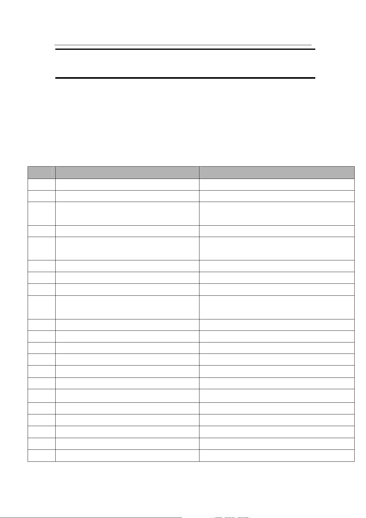
2) Debugging Codes
In general, if a fault of a circuit or part is detected during the system test, the syst
em stops with a code. The debugging codes for system board faults are listed below.
CODE Description Check Item
02 Check CPU Real Mode Change
03 Disable Non-Maskable Interrupts (NMI)
04 Read the CPU type from the CPU internal
register.
06 Initialize System Hardware (DMA,RTC)
08 Set t h e de f ault valu e s for the C h ips e t Re g iste r .
09 Set the Port Flag
0A Initialize the CPU Register Initialization
0B Enable the CPU Cache
0C Set the default values for the CPU Cache
Register.
0E Initialize I/O
0F Initialize the Storage Media
10 Initialize the Power Manager
11 Initialize the Register
13 Initialize PCI Bus Master Reset
14 Initialize the Keyboard Controller
Check that the CPU is supported/Replace the
board.
16 Check the BIOS ROM Checksum Check the BIOS ROM/Check after BIOS update
18 Initialize the 8254 System Timer
1A Initialize the 8237 DMA Controller
20 Check the DRAM Refresh Operation
22 Check the 8427 Keyboard Controller
28 Check the DRAM Memory
SENS R55 5-2
이 문서는 삼성전자의 기술 자산으로 승인자만이 사용할 수 있습니다.
This Document can not be used without Samsung’s authorization.
5. TROUBLESHOOTING
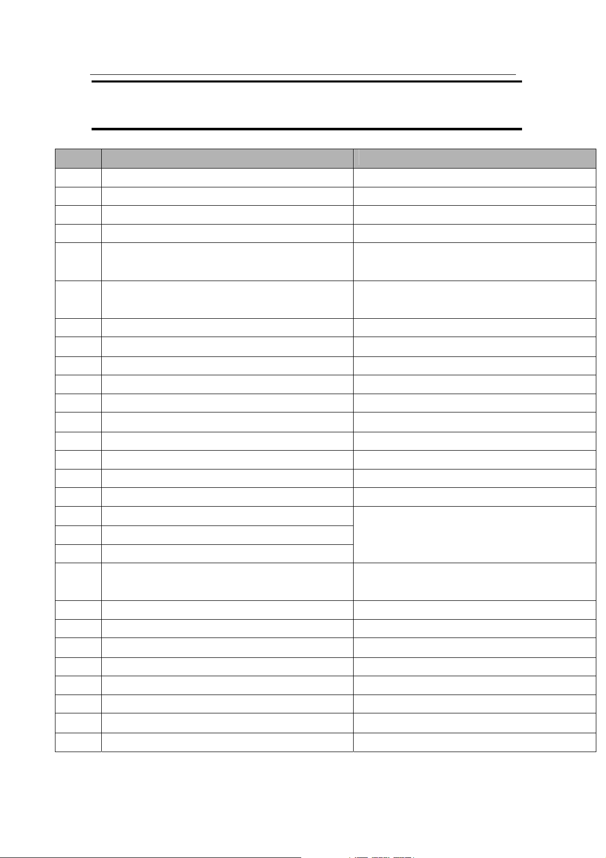
CODE Description Check Item
32 Measure the CPU speed
34 Check the CMOS value
38 Copy the BIOS information to memory
3A Check the CACHE size
3C Set the initial value for the Chipset Register
according to the value saved in the CMOS.
3D Set the initial value for the Super I/O Register
according to the value saved in the CMOS.
42 Initialize the Interrupt Vector
44 Initialize the BIOS Interrupt
46 Check the ROM Copyright
48 Check the video settings using CMOS.
49 Initialize the PCI bus and devices Check after removing the PCI device
4A Initialize the video adapter Check the circuit around the graphic chip
4C Copy the Video BIOS information to memory
50 Display the CPU type and clock speed
52 Check the keyboard
56 Activate the keyboard
5C Check memory (512K~640K)
60 Check Extended Memory
Remove the RTC battery and check if the
CMOS is initialized.
Check the memory module installation status/
Check after a memory replacement
62 Check the Memory Address line
66 Set the initial value for the CPU Cache Register
according to the value saved in the CMOS.
6A Display the External Cache Capacity
72 Check Configuration Error
76 Display Keyboard Error
7C Initialize the Hardware Interrupt Vector
7E Initialize the Auxiliary Processor
84 Initialize and check the Parallel Port
86 RE-INT ON-BOARD I/PORT
88 Initialize the BIOS Data Area (BDA)
Check after the RTC Reset
SENS R55 5-3
이 문서는 삼성전자의 기술 자산으로 승인자만이 사용할 수 있습니다.
This Document can not be used without Samsung’s authorization.
5. TROUBLESHOOTING
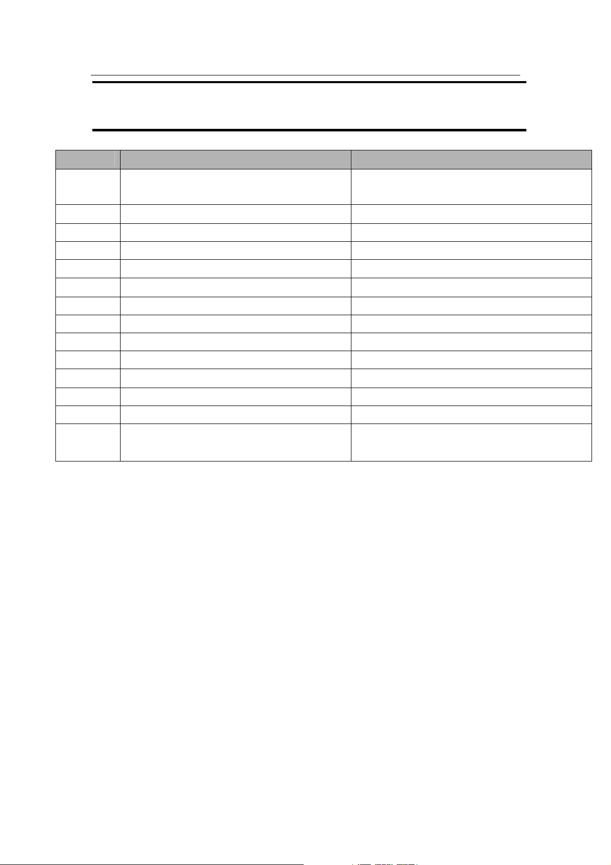
CODE Description Check Item
8A Initialize the Extended (BIOS) Data Area
(EBDA)
8C Initialize and check the FDD Controller
9C Setup Power Manager
9E Enable Hardware Interrupts
A0 Set the Time/Date
AA Check if the F2 key has been pressed
AC Enter SETUP
B0 Check all errors occurring during POST
B4 Beep once
B6 Check the password Check after RTC Reset
B7 Initialize the ACPI BIOS function
BA Initialize DMI
BE Clear Screen
C0 Boot the OS after completing BIOS POST Check the booting priority change in the BIOS
SETUP / Reinstall the OS
SENS R55 5-4

이 문서는 삼성전자의 기술 자산으로 승인자만이 사용할 수 있습니다.
This Document can not be used without Samsung’s authorization.
5. TROUBLESHOOTING
3) Location of Fault and Check Points by Symptom
LCD Related Symptoms
1. The LCD screen is dimmer or the screen color is distorted.
Æ Check the connection status of the LCD cable connector of the main board and the
connection between the LCD cable and LCD inverter.
Æ Replace the LCD cable or LCD inverter.
2. No picture is displayed on the screen.
Æ Check the connection status of the LCD cable connector of the main board and t h e
connection between the LCD cable and LCD inverter.
Æ Replace the LCD cable or LCD inverter.
Æ Check if the memory module is out of order.
3. Cannot adjust the LCD screen brightness.
Æ Check if the LCD inverter is out of order.
Æ Check the BIOS version information or check if the adapter is appropriate.
4. The LCD blinks during use.
Replace the LCD cable and the LCD inverter and check if they are out of order.
Æ Check if the adapter is the appropriate one.
Main System Related Symptom
5. Cannot turn the system on.
Æ If the AC adapter is not connected, check the battery charge status. Even if the
battery is charged, if the remaining battery charge is too low, you may not be able to
boot up the system.
Æ Check if the On Top Board or part of the On Top Board is out of order.
Æ Check if the DC/DC Board is out of order.
Æ Replace the Main Board.
6. The system is turned on, but booting fails or the power turns off immediately.
Æ Since this may happen due to a short circuit within the system, immediately
SENS R55 5-5

이 문서는 삼성전자의 기술 자산으로 승인자만이 사용할 수 있습니다.
This Document can not be used without Samsung’s authorization.
5. TROUBLESHOOTING
disconnect the power from the wall outlet and check if there are any alien objects
such as a loose screw within the product.
Æ Check the connectivity of the connection FPC and cables.
Æ Replace the DC/DC Board and check if the board is out of order.
Æ Replace the memory module and check if the module is out of order.
Æ Replace the Main Board.
7. Cannot insert a PCMCIA card or the remove button does not work properly.
Æ This may happen when the insulator within the PCMCIA slot is pushed inward.
Æ Replace the PCMCIA slot frame and check if it is out of order.
8. Cannot hear the sound.
Æ Check if the volume is set to Mute in the Operating System.
Æ Check the connectivity of the speaker cable and check if the speaker is out of
order.
Æ Check if the Audio Board is out of order.
Æ Replace the Main Board.
9. The HDD is not recognized.
Æ Check the connectivity of the HDD FPC cable and check if the FPC cable is out
of order by replacing it with a new one.
Æ If the HDD is recognized by the CMOS but the ‘Operating System Not Found’
message appears while booting, format the HDD and reinstall the operating
system as this may happen when the operating system is corrupted or the HDD is
out of order. If this does not work, replace the HDD.
10. The touchpad does not work or is working abnormally.
Æ Check the connectivity of the touchpad connection cable.
Æ Replace the touchpad module of the Top Assy and check if it is out of order.
11. The battery is not charged or the battery charge LED malfunctions.
Æ Check the standard power voltage of the adapter.
Æ Replace the DC/DC board and check if the board is out of order.
Æ Check if the battery is out of order.
SENS R55 5-6
이 문서는 삼성전자의 기술 자산으로 승인자만이 사용할 수 있습니다.
This Document can not be used without Samsung’s authorization.
5. TROUBLESHOOTING
5-3 System Diagnosis II
SENS R55 5-7
이 문서는 삼성전자의 기술 자산으로 승인자만이 사용할 수 있습니다.
This Document can not be used without Samsung’s authorization.
5. TROUBLESHOOTING
SENS R55 5-8
이 문서는 삼성전자의 기술 자산으로 승인자만이 사용할 수 있습니다.
This Document can not be used without Samsung’s authorization.
5. TROUBLESHOOTING
SENS R55 5-9
 Loading...