

Samsung NP-R410 Disassembly and Ressembly
- This document cannot be used without Samsung's authorization -
3. Disassembly and Reassembly
3-1. Disassembly and Reassembly of R410
Part
Name
Figure Description
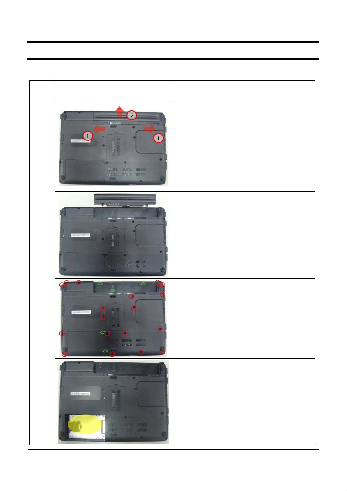
1. Must remove AC Adapter and Battery when
disassembling system.
2. Then, slide buttons in direction of red
arrows No.1, then push battery in direction of
No.2.
3. Have Battery with pushing Battery upward.
Main
System
4. Remove Bottom Screws.
-M2.6xL8:18EA(RED)
-M2xL4:5EA(GREEN)
5. Separate HDD DOOR and remove HDD Door.
3-1
- This document cannot be used without the authorization of Samsung -
3. Disassembly and Reassembly
Part
Name
Figure
Description
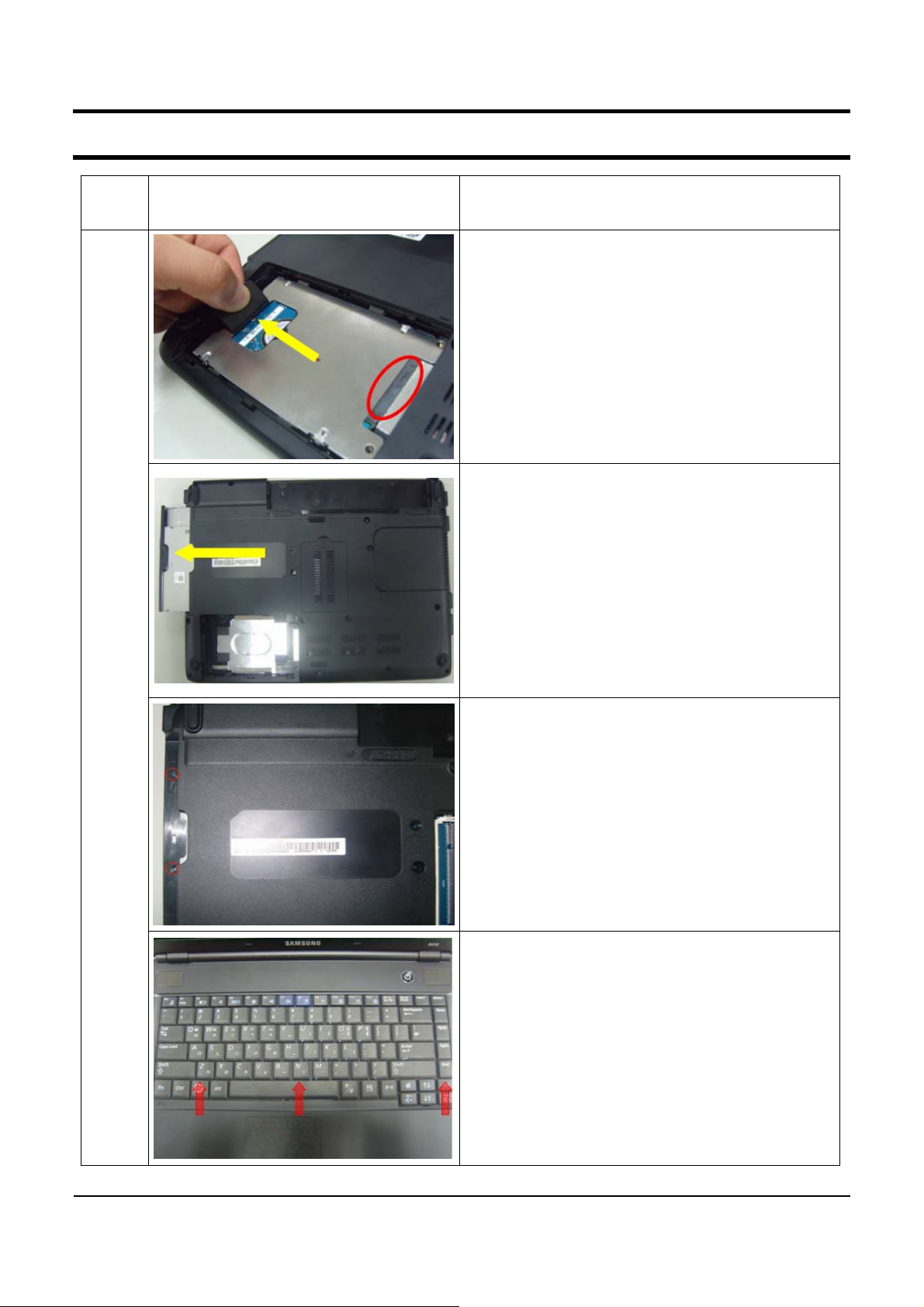
6. Pull Insulator of HDD to 70º from ground.
Then remove the HDD-FPC Connector (in red
circle).
*CAUTION
Don’t pull HDD-FPC with too much force.
Must remove HDD before reversing system.
7. Disassemble ODD like pic.
Main
System
8. After removing ODD, remove screws.
- M2xL4 : 2 EA (RED)
9. Lift up keyboard after pushing hooks inward
with using tweezers.
* CAUTION
Be careful for top scratch when using tweezers.
3-2
- This document cannot be used without the authorization of Samsung -
3. Disassembly and Reassembly
Part
Name
Figure Description
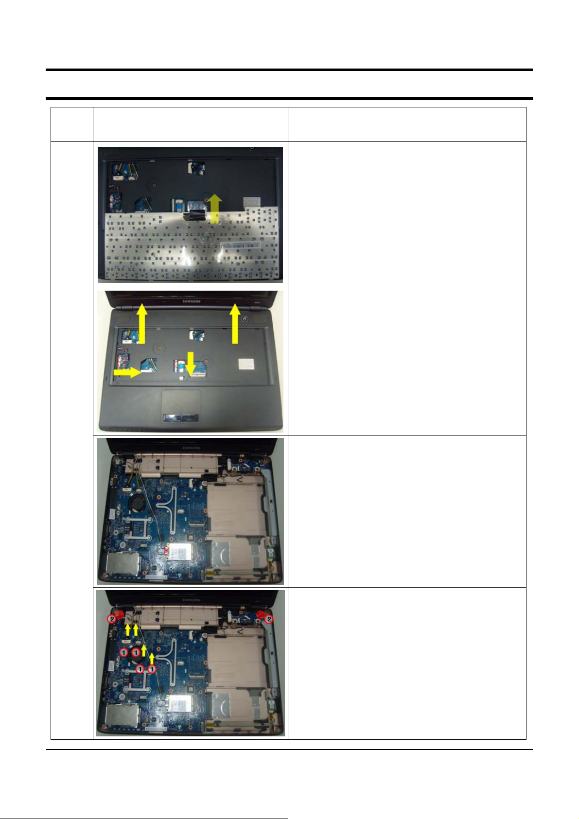
10. After reversing Keyboard backward like pic.
pull out Keyboard FPC with operating Keyboard
Connector.
11. Separate cables between Main PCB and Top.
- MIC Cable : 1 EA
- Speaker Cable : 1 EA
- Touchpad FFC : 1 EA
12. Disassemble Top.
Main
System
13. Separate Antenna Cable connector in
Wireless LAN module.
-. MIMO : Gray
-. Main : White
14. Separate four Cables.
- LCD Cable : 1 EA
- Inverter Cable : 1 EA
- White Antenna cable : 1 EA
- Gray Antenna cable : 1 EA
15. Remove Hinge Screws.
- M2.6xL8 : 2 EA (RED)
3-3
 Loading...