


SAMSUNG New DVM-Pro
User Manual (Cad mode)
English Version
2011. 07.
SAMSUNG DVM-Pro User Guide
2
00
Contents
01 New DVM-Pro Installation & Execution
02 Cad mode outline
03 Cad mode Procedure for using
04 Cad mode interface
05 Step-by-step description of the design
(1) Project Registration
3
5
6
7
15
15
(2) Space Management
(3) Clean Architectural drawing layers
(4) Add In/Outdoor
(5) In/Outdoor Connection
(6) Pit drawing
(7) Pipe drawing
(8) System check
(9) Control Lines drawing
(10) Piping remarks & Piping Diagram
17
18
19
22
24
25
31
33
35
(11) Control Diagram
37
SAMSUNG
SAMSUNG DVM-Pro User Guide
AutoCAD
2010
,
2011
,
2012
based
3
01
New DVM-Pro Installation & Execution
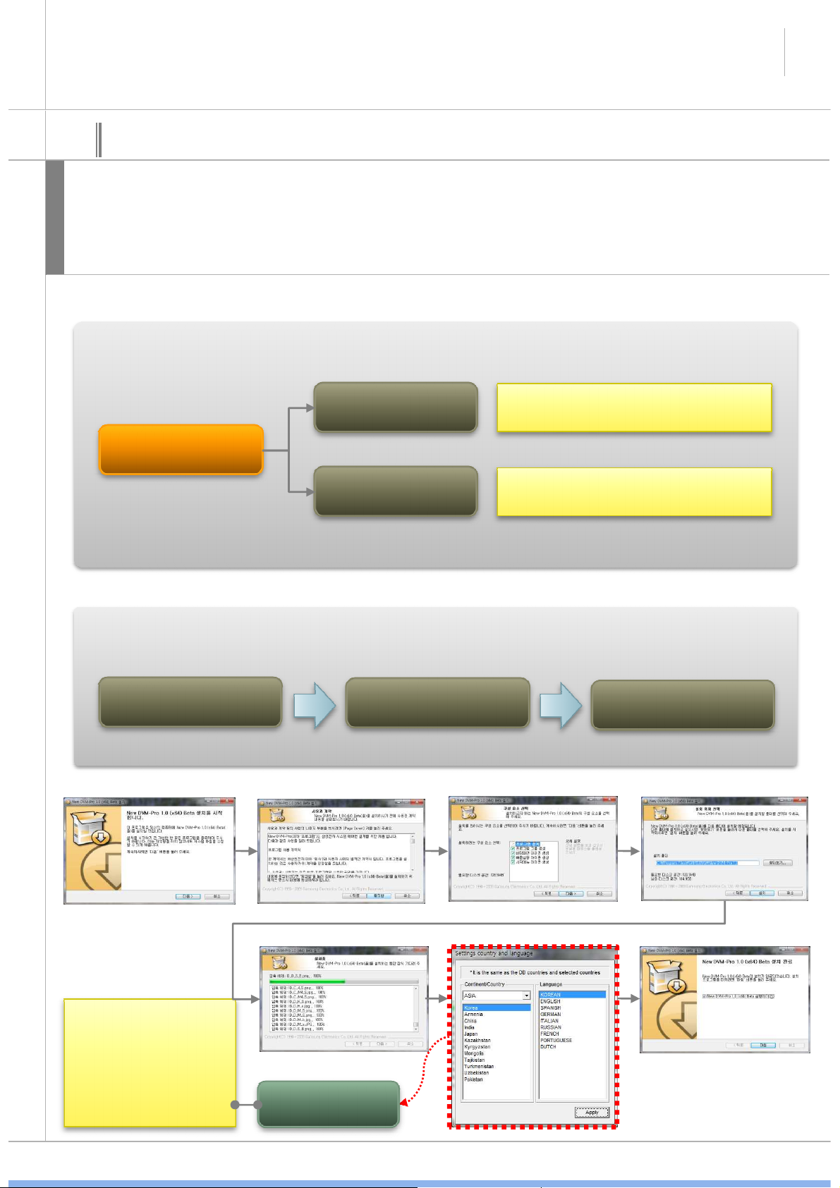
New DVM-Pro is support the Windows XP/Vista/7 32bit, 64bit.
설
After installation, you need to obtain Authorization code in order to use DVM-Pro.
명
New DVM-Pro is composed of ‘Cad mode’ and ‘Sales mode’
New DVM-Pro Configuration
Cad mode
on plug-in programs.
New DVM-Pro
Sales mode
Stand-alone system
Program
installation
Country and language is
determined at the time
of installation. After if
you want to change the
Country and language
settings, you should
requests DVM-Pro
Coordinator.
Program installation & Procedure for using
Request the
Authorization code
Country and
language Select
Using the system
SAMSUNG
SAMSUNG DVM-Pro User Guide
4
01
설
명
New DVM-Pro Installation & Execution
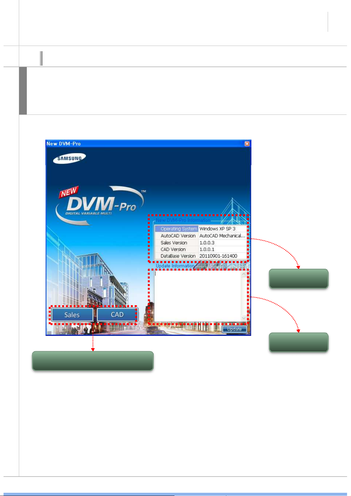
When you run the New DVM-Pro, It is to choose one of two things as New DVM-Pro is composed
of ‘Cad mode’ and ‘Sales mode’
When It need the update, Update Information displayed update information. User can update this
optionally.
‘Cad mode’, ‘Sales mode’ Run button
Current system
information
Update system
information
SAMSUNG
SAMSUNG DVM-Pro User Guide
5
02
Cad mode outline
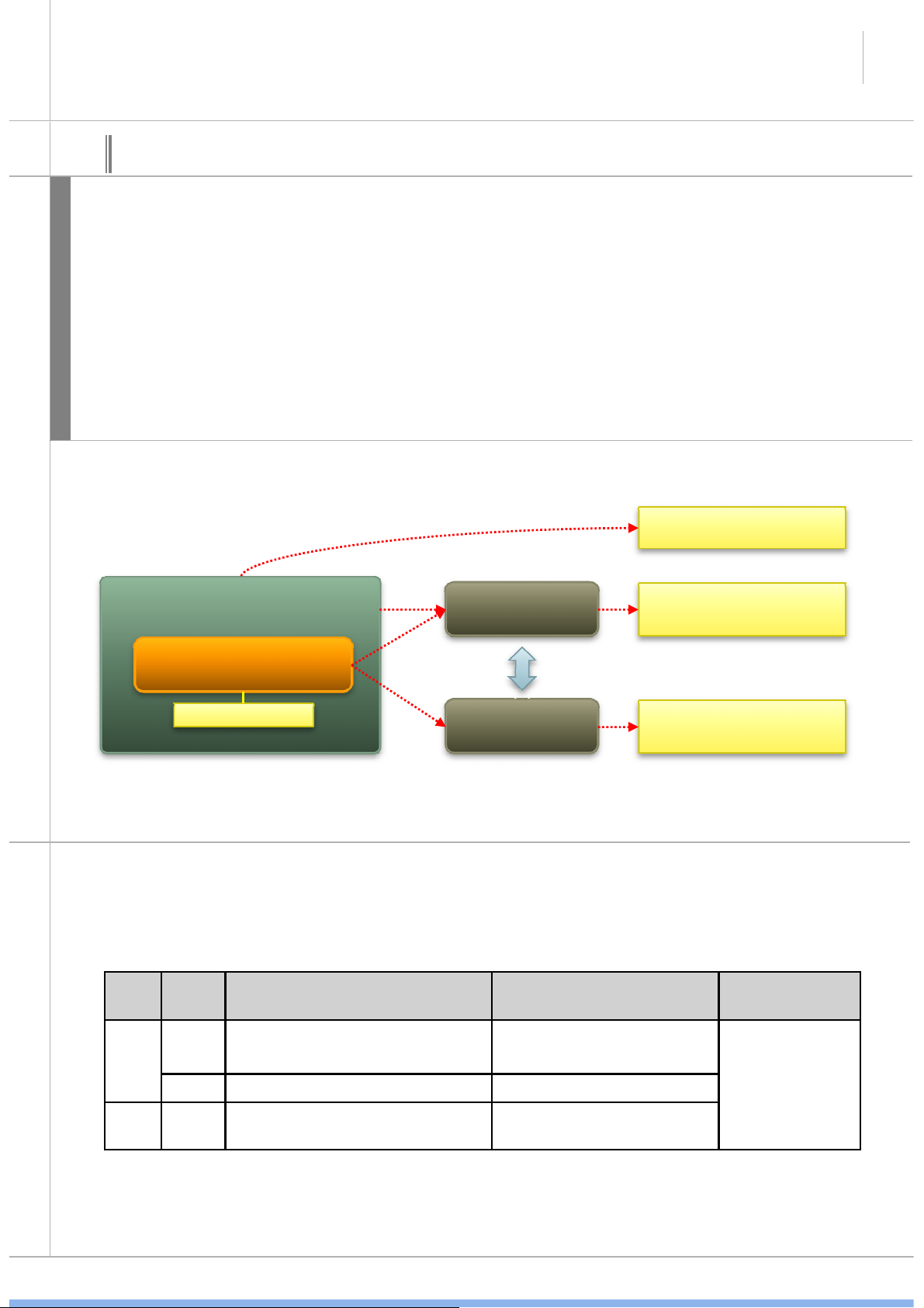
DVM-Pro Cad mode is AutoCAD plug-in program. Auto cad must be installed to use DVM-Pro cad
mode
Designed by the cad mode, data is saved two forms(*.dwg,*.dvm).
*.dwg is drawing file in the cad program.
설
*.dvmx is DB file such as all of In/Outdoor, distribution kit, Capacity Calculation, piping check in
명
drawing files for the design of air conditioning systems.
One project have two forms file. And the two files data is linked.
When you open the DVM-Pro, Open the *.dwg file from Drawing connection icon as *.dvmx file are
automatically generated at the same time of open the DVM-Pro.
AutoCAD Installaion
AutoCAD
*.dwg
• AutoCAD draw file
DVM-Pro Cad mode
Plug-in program
※ Notice
Instructions on how to use the Cad mode
→ Enable/disable command list (When you use AutoCAD command, it may not work properly in
Cad mode. because, DVM-Pro cad mode is plug-in program )
FunctionEnable/
disable
Enable
Insert
Disable CAD command : Insert , Undo, Redo CAD command : Disable
Delete Enable
Dvm command : Add/Copy indoor
CAD command : Copy , Array, Mirror
Dvm command : Delete indoor
CAD command: Erase, Delete, Undo, Red
Indoor Outdoor
*.dvmx
Dvm command: draw outdoor
Dvm command: Delete indoor
CAD command: Erase, Undo, Redo
• DVM-Pro data file
Piping, Pipe
fittings, distributor
kit etc.
All of command
available
→ One drawing file is One building at the time of design in DVM-Pro cad mode.
→ When design in DVM-Pro cad mode, if you change the layer, *.dvm connection may be
lost.
SAMSUNG
SAMSUNG DVM-Pro User Guide
Clean architectural
•
When
add
indoor,
The
area
recognized
the
room
anditwill
System check
system
check
and
check
again
.
08
03
01
02
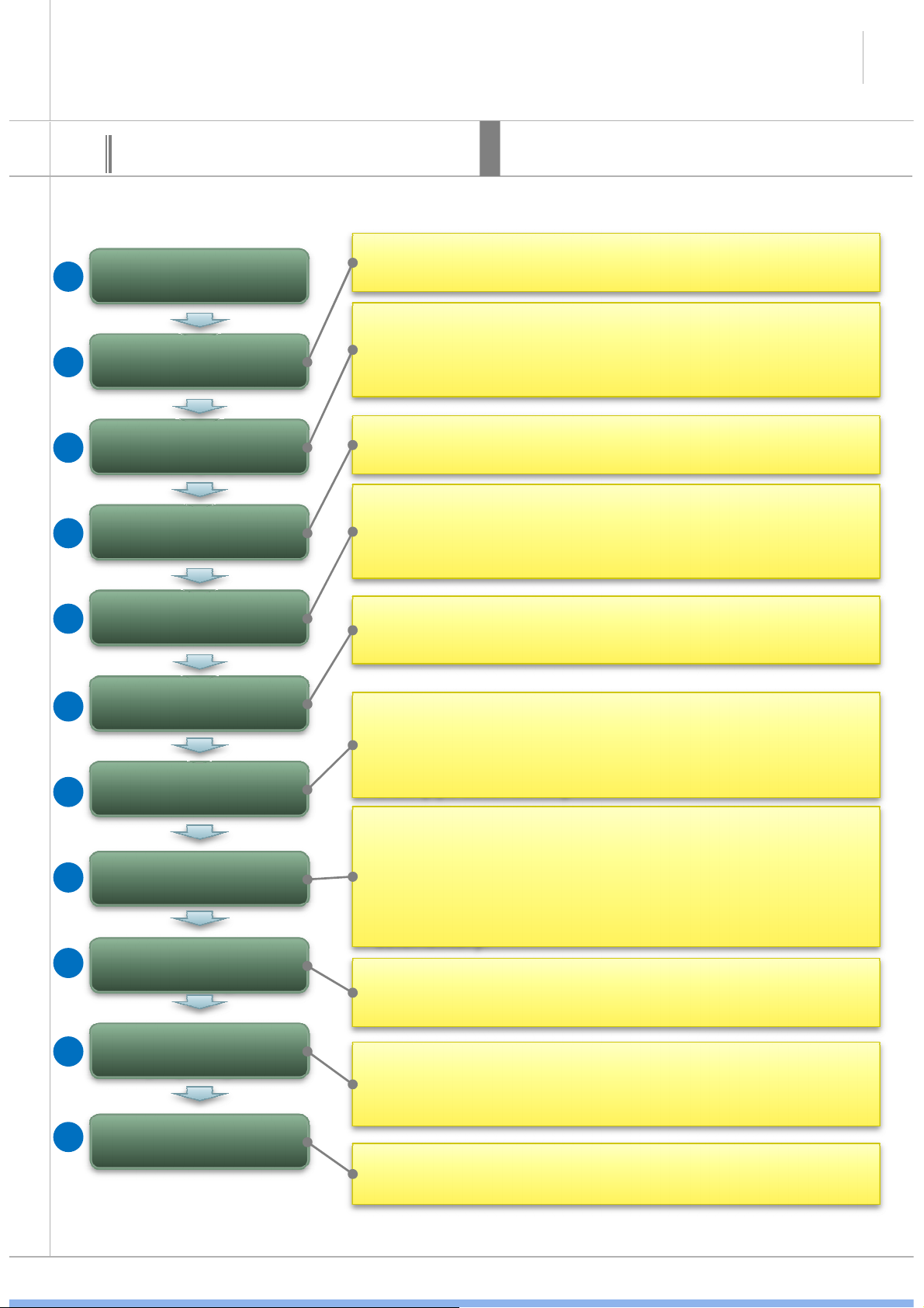
Cad mode Procedure for using
Project Registration
Space management
6
This is cad mode procedure for using when design the new
project. This procedure is not included modify procedure.
Explain
• Add the floor in the space management windows
• Specify the floor boundary
• When design air-conditioning drawing, need to architectural
drawings, but almost no work to modify. So, disabling a
layer of architectural drawings and change gray color to
help convenient design work.
03
04
05
06
07
09
drawing layers
Add In/outdoor
In/Outdoor
connection
Pit drawing
Pipe drawing
Control lines
drawing
be added room Automatically.
• It can continue to draw level that all of indoor and outdoor
unit must be a connection.
• After select in in/outdoor connection windows, you can
drawing outdoor.
• Select the pit in the pit drawing window, you can draw
multiple outdoor pit.
• It can draw the pipe through Draw pipe/pipe accessories,
Draw communication wires/wired remote controller.
• It can connected main pipe to multiple indoor at once,
automatically Through Draw piping automatically, Draw
drain pipe automatically
• Refrigerant pipe connection , pipe length and pipe level
difference etc is checked.
• When system check is error, modify the part of guided in
• Drain pipe connection is checked.
• the end of the system check, pipe diameter is placed
automatically.
• If click on the indoor to indoor, Communication wires and
wired remote controller can connected by a line.
10
11
Piping remarks &
Piping Diagram
Control Diagram
• Insert the pipe remarks
• Insert piping diagram by click on the list in order on the
piping diagram field of report.
• Insert control diagram by click on the list in order on the
control diagram field of report.
SAMSUNG
SAMSUNG DVM-Pro User Guide
DVM
-
Pro
DVM
-
Pro
Menu
7
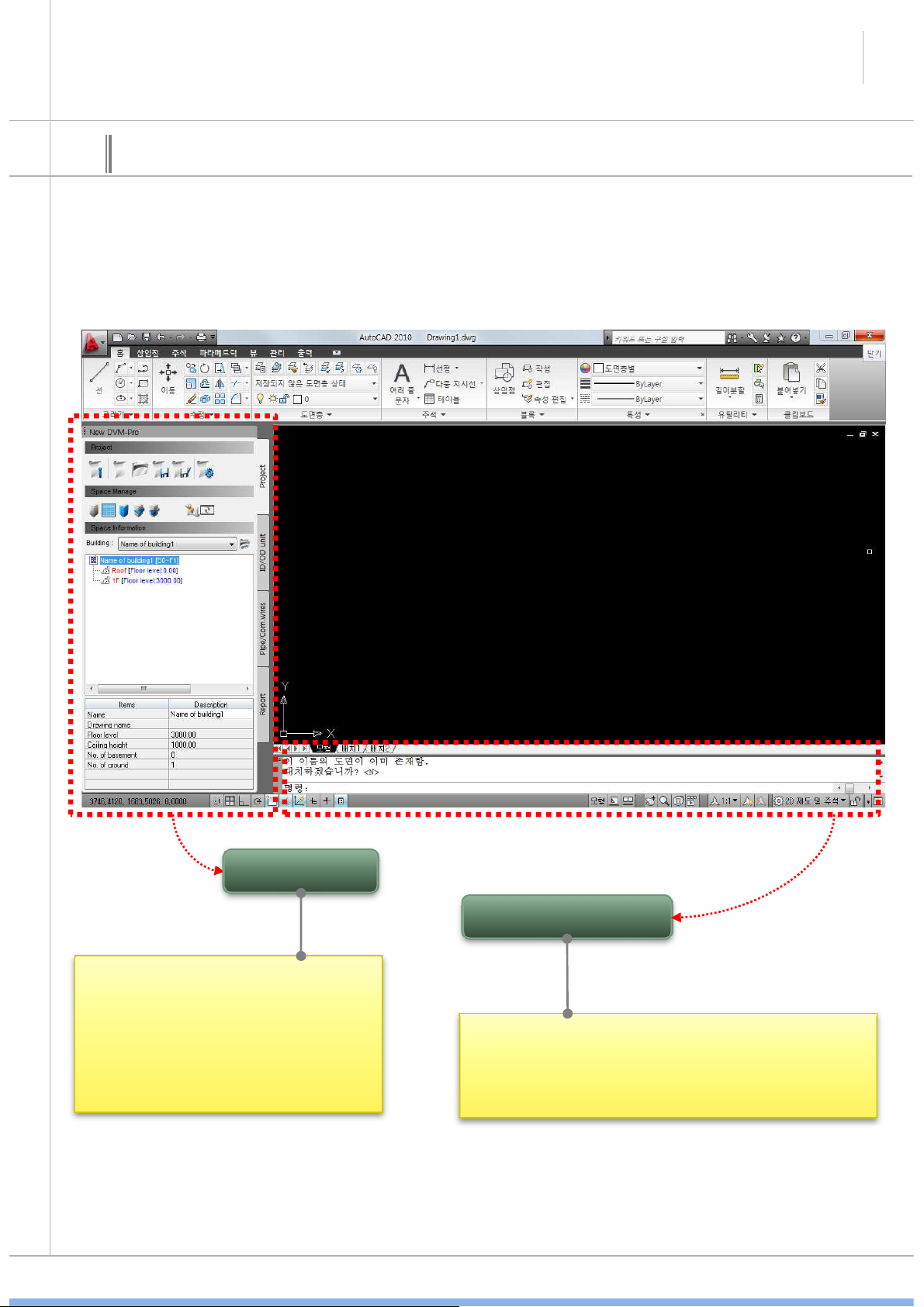
04
Cad mode interface
• It used in DVM-Pro cad mode
• It can control all progress
functions in DVM-Pro cad mode
• It made in a palette form of Auto
cad
AutoCAD commend
• Built in Auto cad interface
• More options for running the command
information can be checked in cad mode.
SAMSUNG
SAMSUNG DVM-Pro User Guide
canbedesigned
exact
temperature
for
•
Save
project
8
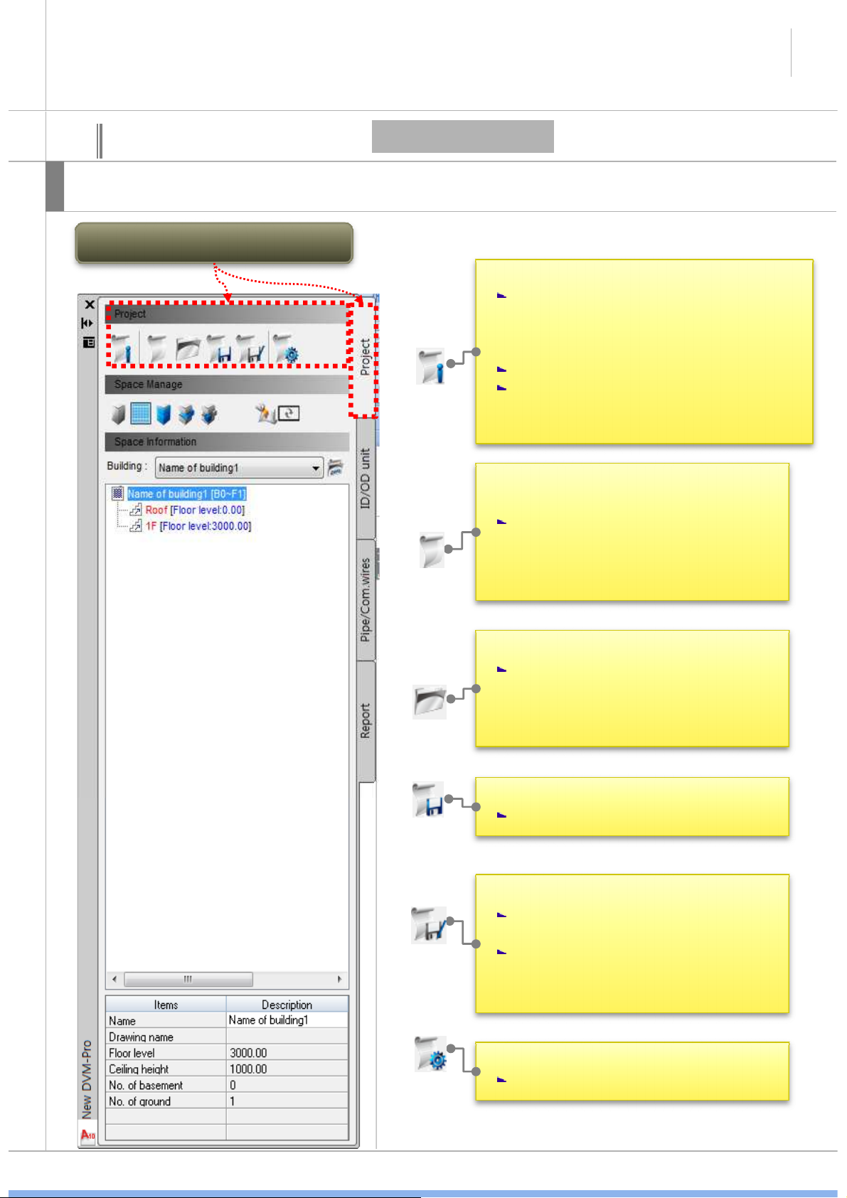
04
Explain
Cad mode interface
Possible to create the new project and start the project in cad mode palette.
New Project/Management Menu
Project
• View and modify the project information
Possible to modify and view the
project name, customer information,
architect information in the ‘modify
the project information’ window
Possible to view save path.
It can select the local temperature. It
the region.
• New project
It create a new project menu. It can
enter the project information from
same ‘project information window’.
• Open project
Select the existing project files and
open menu, when open the *.dvmx
file, open the linked * .dwg file
automatically.
Save the current project.
• Save as the current project
Save the current project with a
different name
If this saved same path, original
*.dwg file may be lost. It should be
save new folder.
• Preferences
Set the detail using menu
SAMSUNG
SAMSUNG DVM-Pro User Guide
•
Select
the
building’s
drawing
9
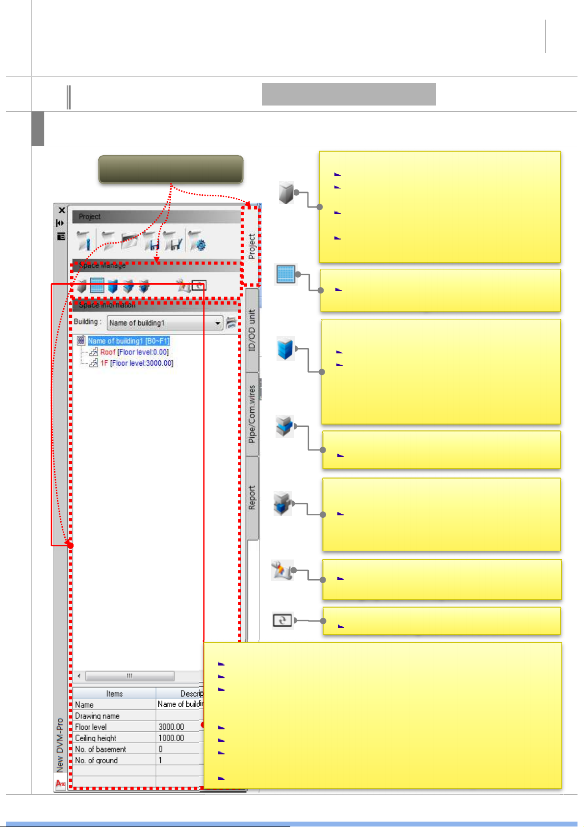
04
Explain
Cad mode interface
It can register and start a new project when using command palette of cad mode.
Space management
menu
Project (Space management)
• Space management
Enter the building name.
It can create/modify the each floor, floor
height, distance between ceiling.
It can create/modify the room which get
into indoor .
It can upload the Excel file which include
building, floor, room information.
Select the corresponding drawing of the
selected building.
• Floor area select batch
Select the floor area continuously.
It’s progress First floor in order to roof
floor. First floor of the specified zoning
box is intended to specify the upper
floors by clicking.
• Floor area individual selection
Select the floor area.
• Room zoning
If add the room in information, it is
connected to drawing.
• Architectural drawing background processing
Change the architectural drawing color
in gray and lock layer
• Renewal
Renewal the space information.
• Space information list
It can select the building.
It can view floor, room information of building.
All of the floor information displayed Next to the building
list(ex. B0~F1) ‘B’is the basement, ‘0’is basement floors, ‘F’ is
the ground, ‘1’is the ground floors.
Floor level displayed next to the floor list.
Area information displayed next to the room list.
If click each building, floor, room, More information can be
found below.
If double click each floor and room, The drawing is zoom-in.
SAMSUNG
SAMSUNG DVM-Pro User Guide
indoor
number
in
‘Add
indoor
unit
’
window
.
connection
impossible
of
the
indoor
remove
10
04
Explain
Cad mode interface
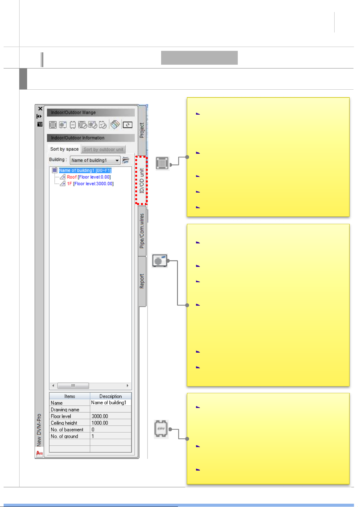
This interface is possible to create and manage the in/outdoor.
In/Outdoor - 1
• Add indoor unit
After specify the area, ‘add indoor unit
window’ is open.
- If the room area already designated,
‘enter’ key no need to specify the area as
it’s open a window directly.
Possible to create & view indoor information
such as room name, area, unit load per area,
It have three menu(Indoor name, family,
type) to choose indoor model.
Indoor spec displayed indoor information
box.
Placed indoor unit in a variety of ways.
• Draw outdoor unit
a. After selected the indoor unit which
connected to outdoor unit, ‘add outdoor
unit’ window open.
b. Select the combination ratio, outdoor type,
outdoor name, by the outdoor group, series.
c. outdoor combination ratio is list-up within
the above conditions. And image, drawing,
outdoor spec is displayed.
d. connection possible or impossible of
indoor model information is displayed indoor
information box. It’s displayed in blue, red,
each. Also, possible to add, remove or
about this indoor unit.
e. After select outdoor from a list, select the
detail menu from command box and insert it.
f. if you delete the outdoor unit, it’s
outomatically turned off between the indoor.
• Add ERV
After specify the area, ‘add ERV unit’ window
is open.
- If the room area already designated,
‘enter’ key no need to specify the area as
it’s open a window directly.
Possible to check the number of ERV
through ventilation requirements, time,
personnel information .
If click each ERV indoor, More information
can be found below.
SAMSUNG
SAMSUNG DVM-Pro User Guide
11
04
explain
Cad mode interface
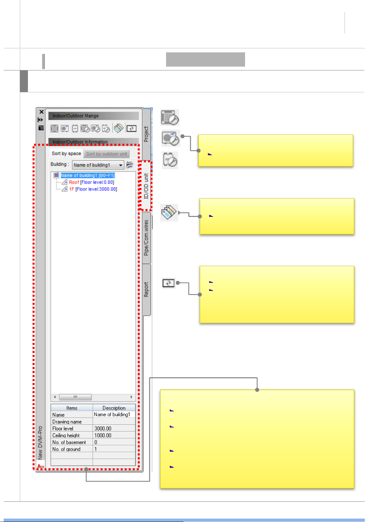
This interface is possible to create and manage in/outdoor
In/Outdoor - 2
• Modify the indoor, ERV indoor, outdoor.
Possible to modify the each unit.
• Select the accessories
Possible to set the indoor and outdoor
accessories.
• Renewal
Space information renew as recently.
You don’t need to this menu every time.
Space information renew automatically.
But if it no work, you can renew by this
menu.
• Space information list of in/outdoor
Possible to check each building, floor, room location
information and unit location information.
It’s same the project tab information that displayed
next to building, floor, room information and model
name is displayed next to in/outdoor list.
If click each building, floor, room, More information
can be found below.
If double click each floor and room, The drawing is
zoom-in.
SAMSUNG
SAMSUNG DVM-Pro User Guide
and
select
the
indoor
which
will
connect,
connected
the
pipe,
pipe
automatically
connected
the
pipe,
pipe
automatically
disconnect
where
the
accessories
enters
.
12
04
Explain
Cad mode interface
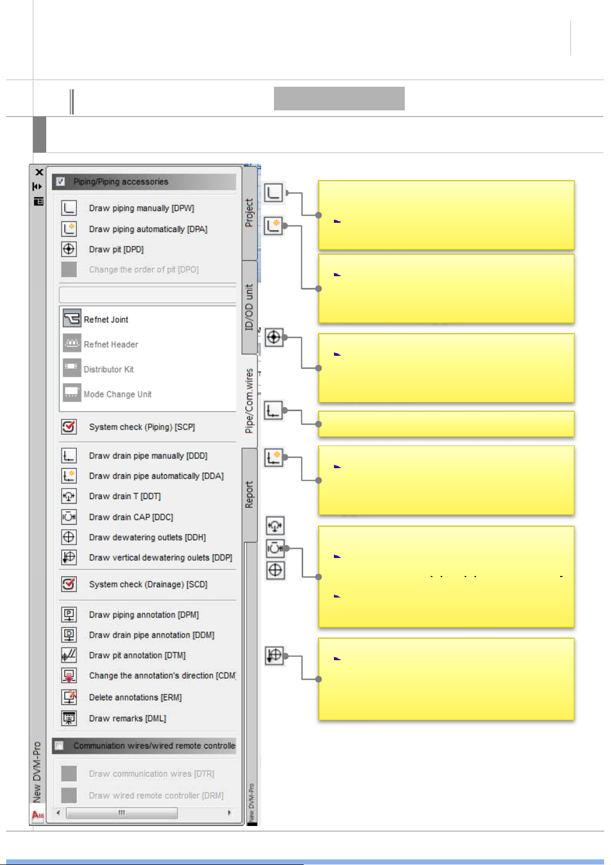
This interface is possible to create and manage piping/control line.
Piping/control line
• Draw piping manually
When connect pipe using refnet joint,
• Draw piping automatically
After Select the main pipe which drawn
than enter, indoor will automatically
connect to main pipe.
• Draw pit
Select and check the deployment method
of outdoor pit in ‘draw pit’window. And
click the insertion point, and then copy
to each floor.
• Draw drain pipe manually
• Draw drain pipe automatically
After draw the main pipe, select the
indoor which will connect and click enter
key. Then indoor will connect the main
pipe.
• Insert the each pipe accessories on pipe.
If pipe accessories(refnet joint, Tee joint)
If you delete the pipe accessories which
connect the pipe, pipe connect again.
• Draw vertical dewatering outlets
Select and check the deployment method
of outdoor pit in ‘ draw vertical
dewatering outlets’window. And click the
insertion point, and then copy to each
floor.
SAMSUNG

SAMSUNG DVM-Pro User Guide
Check
the
status
of
the
design
drawings
and
•
Communication
wires
&
controller
13
04
Explain
Cad mode interface
This interface is possible to create and manage the piping/control line.
Piping/control line
• Pipe accessories
a. when select the outdoor unit, accessories
activation that connectable.
• System check
present the problem. It make users to modify
it.
System check can determine the suitability of
design and can be minimized design errors by
user.
• Draw piping and drain annotation/change the
annotation’s direction.
After finished the system check, piping
annotation draw to center of each pipe with
a choice of all/zoning option.
If use the change the annotation’s direction
menu and click the piping annotation, it will
change.
• Draw pit annotation
After select the direction of pit and click the
enter key, annotation pit inserted.
If you select this, you can show only
communication wires & controller layers.
• Draw communication wires
Darwing from the pit or free space, then
click indoor and next indoor. When selection
finished, click the enter key.
• Draw wired remote controller manually
Clicking from the indoor, then when
selection finished, click the remote location
and enter key. When this finished, remote
control icon will insert.
SAMSUNG

SAMSUNG DVM-Pro User Guide
drawing
.
diagram
in
order
to
the
listofdiagram
diagram
in
order
to
the
listofdiagram
menu
.
14
04
Explain
Cad mode interface
This interface is possible to create and manage the piping/control line.
Report
• Report
Select the report list and insert the report in
• Pipe diagram
Insert the pipe diagram in order to the list
of pipe diagram menu.
- Draw layer of floor
- Arrange indoor & outdoor unit
- Draw vertical dewatering outlets
- Draw drain pipe
- Draw annotation of outdoor unit’s pipe
- Draw remarks
• Power/communication/controller diagram
Insert the power/communication/controller
- Draw layer of floor
- Arrange indoor & outdoor unit
- Draw wired remote controller manually
- Draw indoor’s power wiring
- Draw outdoor’s power wiring
- draw outdoor’s communication
- Draw interface module
- Draw unit of controller solution
- Draw remarks
SAMSUNG

SAMSUNG DVM-Pro User Guide
15
05
• project info.
• Check and edit.
02
• Assignment
(drawing file)
Step-by-step description of the design
01
01-1
(1) Project registration
• New project
• It can create new *.dvm file.
• When select the icon, asks whether to
save as when you open the DVM-Pro
program, *.dvm new file is already open.
• Select open method the drawing
• All open drawing is display in this
window. And if you choose one, that
one is open and connect.
• Actice drawing of all open drawing is connect the project building.
SAMSUNG
• Open where architectural
drawing select window.

SAMSUNG DVM-Pro User Guide
02.Save
the
project
16
05
Step-by-step description of the design
01 02 03
(1) Project register and save
01.Open the project
• when DVM and DWG file is saved same folder and you open the DVM file, DWG file open
automatically. If it’s saved no same folder and you open the DVM file, DWG file no open. So
you should use Assignment(drawing file) menu to open the DWG file.
save the new project first time : when specify the path to the DVM file and save, DWG file save
same path with DVM file from the original position.
*if you save in same folder which saved recently, open DWG file path is same save path so
DWG file will be over written. Then original file may be missing.
save after saved : it save same path and over written.
03.Save as project
this menu is save again in other path.
SAMSUNG

SAMSUNG DVM-Pro User Guide
proceed
and
add
the
room
proceed
and
add
the
room
17
05
Step-by-step description of the design
• Space management
01
(1) Management (building/floor/room)
• Method of add room
- There is pre-and enter all
of room information in
management (room area,
unit load per area etc)
when add the indoor. And
if you want to delete the
room, you should delete in
only space management
window.
02
• Hold the block down which same add
the room number from same line on the
floor.
02
• Choose the name which need to delete
and click this button. Then that room
will be delete.
03
04
SAMSUNG

18
SAMSUNG DVM-Pro User Guide
05
Step-by-step description of the design
02
• Process the grayscale,
01
lock layers
(2) Management (building/floor/room)-1
(3) Process the grayscale, lock layers
• Zoning(all floor)
• There is zoning(each floor)
menu also. You can zoning 1
by 1.
03
04
05
06
SAMSUNG

SAMSUNG DVM-Pro User Guide
03
19
05
Explain
01
Step-by-step description of the design
When you add the indoor, you can add the room. In/outdoor information and room area is displayed interface left side and
room information will be utilized by after reports.
(4) Add in/outdoor-1
04
When add the indoor, model
name is different, depending
on the model type. You
should be designed to
distinguish between model
type and model type of each
indoor unit can be connected
only as outdoor.
• Enter the indoor unit and
room information
05
02
• Zoning(room)
06
- If Add the indoor unit in the same manner as above, room name connect the room
area in drawing. Then indoor insert in that room area.
SAMSUNG

SAMSUNG DVM-Pro User Guide
20
05
Explain
Step-by-step description of the design
The placement of the indoor unit method is three method ( 1) center 2) user deployment 3) copy ) indoor unit and room can
copy and it displayed “in/outdoor information’ window in real-time
When insert the block, Ctrl key is redirect and Tab key is point conversion.
Copy/move
(4) Add in/outdoor-2
• Copy the indoor unit and room on the second floor
• Add the indoor unit on the first floor
• Add the CAC and FJM indoor unit
CAC, FJM can be added in the same method.
Wall mounted, stand type are insert 1 by 1.
when insert the wall mounted indoor,
attaches to the wall.
1way cassette indoor insert 1 by 1. and after
enter the distance from the wall, attaches to
the wall.
SAMSUNG

SAMSUNG DVM-Pro User Guide
21
05
Explain
Step-by-step description of the design
This is explain of name block.
• Model name
RD540HHXH2
(4) Add in/outdoor-3
• Model name
ND0834HXB1
• Zone information
This number mean connection of in/outdoor.
Connection indoor and outdoor are same number. So
you can see the connection.
In/outdoor name.
The first line is capacity,
The second line is model
name to the rest.
SAMSUNG

SAMSUNG DVM-Pro User Guide
01
22
05
Explain
Step-by-step description of the design
If you can continue to draw level, all of indoor connect the outdoor. And you can draw the outdoor after select in ‘in/out
connect’ window.
(5) Connect in/outdoor-1
• Unable to connect indoor
02
03
04
• Connect the FJM in/outdoor
Connect the same method.
SAMSUNG

SAMSUNG DVM-Pro User Guide
23
05
Explain
01
Step-by-step description of the design
If you select the in/outdoor which will connect, In/outdoor connection of CAC is connect simply.
(5) Connect in/outdoor-2
02
03
SAMSUNG

SAMSUNG DVM-Pro User Guide
24
05
Explain
Step-by-step description of the design
After setting the number of columns and line Pit, click on the location of the drawing. Pit draw by outdoor and if you put the
mouse near the pit, you can see a connection outdoor image when you draw the piping.
02
01
(6) Draw pit
• Speed command :
you can execute the menu
without click. When you
enter this command,
menu execute.
• Copy the pit where other
floors.
03
04
SAMSUNG

SAMSUNG DVM-Pro User Guide
•ifyou
put
the
mouse
near
the
pit,
you
can
seeaconnection
can see connection
25
05
Explain
Step-by-step description of the design
This is connection the piping. Recognize the connection point automatically without click the direct connection point.
• When you enter this command, menu execute.
• All of the unit have connection point when mouse comes
close. If click near piping, it connect this point automatically.
Also, pipe accessories are same.
outdoor image, outdoor name, model name when you draw
the piping.
(7) Draw piping-1
01
02
If you put the
mouse near the
outdoor unit, you
which look like ‘x’.
• When you draw distribution pipe, drawing like behind capture
and Enter. Than you can choose direction and you will see the
refnet joint direction which before choose.
03
01
02
03
SAMSUNG

SAMSUNG DVM-Pro User Guide
01
03
•
When
you
draw
distribution
26
05
Explain
Step-by-step description of the design
It’s explain to draw the piping. Auto/manual pipe is available. You can various forms of draw the pipe.
You can draw through draw piping manually. It have draw piping automatically menu. You can connect indoor to main piping.
(7) Draw piping-2
Select the
indoor units to
automatically
connect
02
Click the
main piping
04
05
• When you enter this command,
menu execute.
pipe, drawing like behind
capture and Enter. Than you can
choose direction and you will
see the refnet joint direction
which before choose.
After click the Enter key, select the
direction of refnet joint.
Connect the last indoor / Select the pipe leaving
SAMSUNG

SAMSUNG DVM-Pro User Guide
•
Tee and cap draw the same
27
05
Explain
Step-by-step description of the design
It’s explain to draw the piping. Auto/manual pipe is available. You can various forms of draw the pipe.
Also you can draw piping accessories.
When insert the block, Ctrl key is redirect and Tab key is point conversion.
01
(7) Draw piping-3
02
If pipe accessories(refnet joint,
Tee joint) connected the pipe,
pipe automatically disconnect
where the accessories enters. And
you can choose direction of refnet
joint through use Ctrl
If you delete the pipe accessories
which connect the pipe, pipe
connect again.
method.
• Header, MCU draw the same
method.
• When draw the piping from piping
accessories, if you don’t want to
go to a different point, click the
ctrl key.
01
SAMSUNG

SAMSUNG DVM-Pro User Guide
01
28
05
Explain
Step-by-step description of the design
It’s explain to draw the drain piping, Auto/manual pipe is available. You can various forms of draw the pipe.
It have draw drain piping, draw Tee, draw cap. And It have draw drain piping automatically menu. You can connect indoor to
main drain piping.
(7) Draw piping-4
• When you enter this command, menu execute.
03
02
03
Select the
indoor units
to
automatically
connect
Click the main
drain piping
01
04
After enter key
05
After enter key
04
SAMSUNG

SAMSUNG DVM-Pro User Guide
•
When draw the drain piping from drain piping, if drain piping draw from drain piping,
29
05
Explain
Step-by-step description of the design
It’s explain to draw the drain piping, Auto/manual pipe is available. You can various forms of draw the pipe.
• If you delete the Tee and drain which connected the Tee, returns to original state of
the drain piping. And Elbow is delete that include the deleted drain piping.
• If Tee joint connected the pipe, pipe automatically disconnect where the accessories
enters.
• If you put the mouse near the unit, you can see connection which look like ‘x’. When
click the ‘x’, drain piping will appear to block and the.
Tee draw automatically.
(7) Draw piping-5
01
01
02
03
Put on the indoor unit
block and click the ‘x’
02
SAMSUNG

SAMSUNG DVM-Pro User Guide
piping
diagram
.
piping
diagram
.
30
05
Explain
Step-by-step description of the design
If Draw dewatering outlets and draw vertical dewatering outlets. draw vertical dewatering outlet’s number is same, same
number is same location of the other floor. Than this information used diagram in report. Tab.
If you selected same number
when you insert the drain pit, all
same number pit is one line in
02
(7) Draw piping-6
01
Draw the dewatering outlets: select the insert point
Select the insert point
SAMSUNG

SAMSUNG DVM-Pro User Guide
02
02
•
When
system
check
is
error
•
When
system
check
is
error
•
Double
click
after
check
the
31
05
Explain
Step-by-step description of the design
Refrigerant pipe connection , pipe length and pipe level difference etc is checked. And When system check is error, modify
the part of guided in system check and check again. Drain pipe connection is checked. the end of the system check, pipe
diameter is placed automatically.
• Select the outdoor for system check
(8) System check-1
01
03
04
error massage.
05
• Zoom-in the error location.
SAMSUNG

SAMSUNG DVM-Pro User Guide
02
02
32
05
Explain
Step-by-step description of the design
Pass the drawing check, test a variety of check list. If it have a problem, display part of the problem and explain the cause of
the problem. Also, finish the check, pipe diameter is placed automatically.
01
(8) System check-2
• Check the drawing and edit.
• After the resolution, do the
system check again until It
should not be problem.
SAMSUNG

SAMSUNG DVM-Pro User Guide
33
05
Explain
Step-by-step description of the design
Select the communication wires/wired remote controller, draw the communication wires/wired remote controller.
• When you enter this command, menu execute.
• Select check box the piping/piping accessories or communication
wires/remote controller, selection layer is active. So, you can
distinction .
refrigerant
(9) Controller wire-1
Drain piping
01
Put on the near side, all of
unit outside of indoor is
possible to connect.
02
03 0705
04
06
• Click the connection indoor in order and
then when you enter, complet the
connection.
SAMSUNG

SAMSUNG DVM-Pro User Guide
34
05
Explain
Step-by-step description of the design
Select the communication wires/wired remote controller, draw the communication wires/wired remote controller.
• When you enter this command, menu execute.
• Select check box the piping/piping accessories or communication
wires/remote controller, selection layer is active. So, you can
distinction .
• Click the connection indoor in order and then when you enter,
complet the connection.
Put on the near side, all of
unit outside of indoor is
possible to connect.
(9) Controller wire-2
02
01
03 04
SAMSUNG

SAMSUNG DVM-Pro User Guide
35
05
Explain
Step-by-step description of the design
Design the piping remarks and insert to drawing.
Click the piping diagram list in order. then Design the piping diagram.
01
(10) Piping remarks & Piping Diagram-1
02
03
Drain pit Connection by clicking.
03
01
• Repeat the order of outdoor and indoor which
include the outdoor. You can insert this block to
click the rocation.
• If dewatering outlets is not connect the drain
piping, ddwatering outlets is displayed with block.
• You can change the direction of piping to use Ctrl
key
01
02
When you Click and enter ,
03
Display the piping remarks.
02
Specifies the arrow keys to
move pipe height.
SAMSUNG

SAMSUNG DVM-Pro User Guide
36
05
Explain
Step-by-step description of the design
Click the piping diagram list in order. then Design the piping diagram.
Click the direction
03
(10) Piping remarks & Piping Diagram-2
Click
01
the
indoor
02
Enter
01
Click the insert point
SAMSUNG

SAMSUNG DVM-Pro User Guide
01
01
37
05
Explain
Step-by-step description of the design
Click the piping diagram list in order. then Design the control diagram.
03
(11) control Diagram-1
02
• You can change the direction of the remote
controller. it depend upon the direction of
the mouse.
• It displayed such as indoor group of the
plans.
Drain pit connection by clicking
03
01
01
02 03
02
When you click and
enter, display the power
wire information.
Specifies the arrow keys to
move pipe height.
SAMSUNG

SAMSUNG DVM-Pro User Guide
38
05
Explain
Step-by-step description of the design
Click the piping diagram list in order. then Design the control diagram.
01
Click the
outdoor
02
(11) control Diagram-2
Click the direction
03
Enter
Click the insert point
Click
the
insert
point
Click the direction
03
01
02
01
02
Enter
03
Click the direction
Click the
outdoor
Enter
SAMSUNG
 Loading...