

Samsung MW5780H, MW5780H-XAA Alignment and Adjustments
Samsung Electronics
5. Alignment and Adjustments
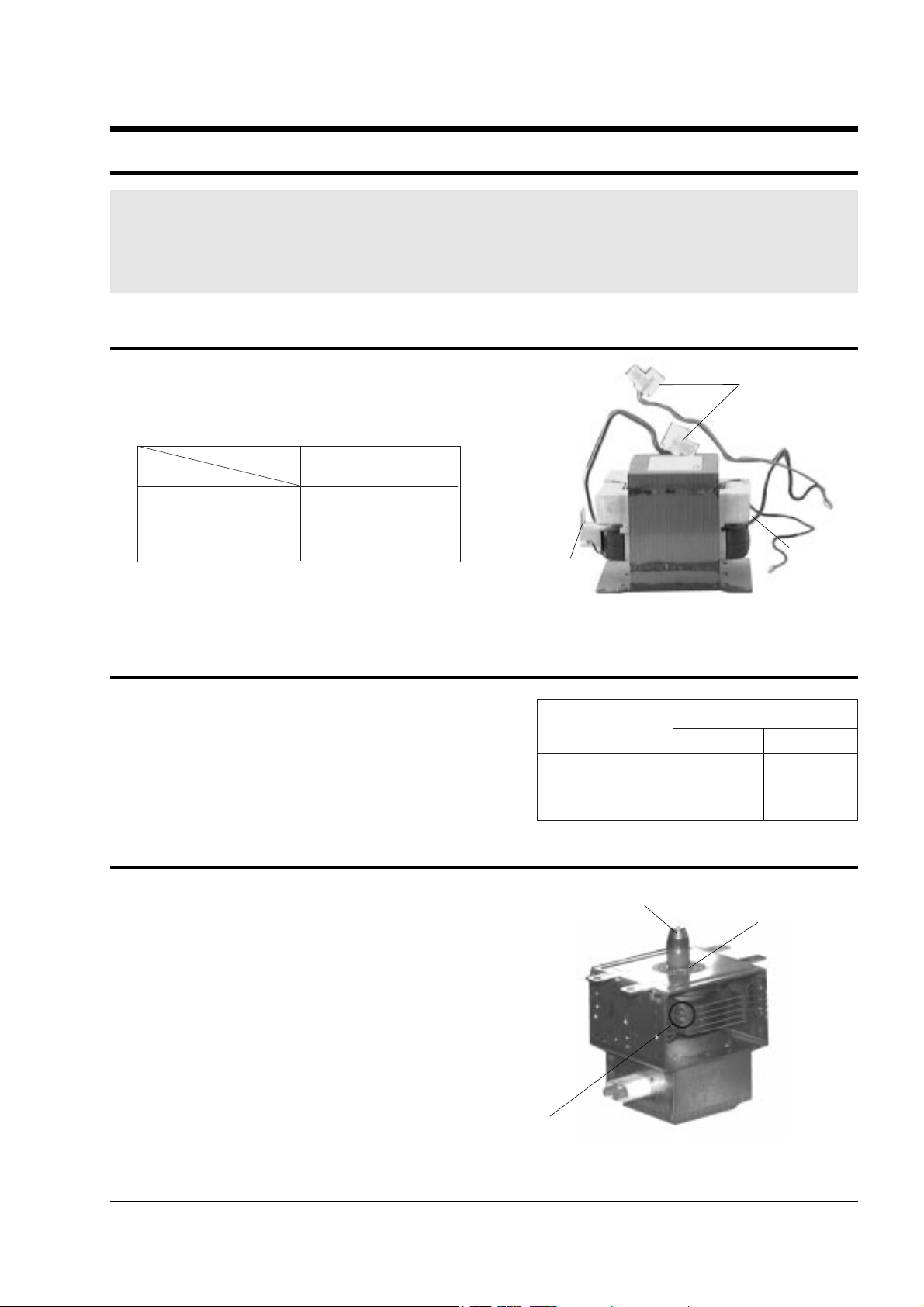
5-1 High Voltage Transformer
5-2 Low Voltage Transformer
5-3 Magnetron
5-1
1. Remove connectors from the transformer terminals
and check continuity.
2. Normal resistance readings are as follows:
(Room temperature = 20ûC)
1. Continuity checks can indicate only an open
filament or a shorted magnetron. To diagnose an
open filament or shorted magnetron :
2. Isolate the magnetron from the circuit by
disconnecting its leads.
3. A continuity check across the magnetron filament
terminals should indicate one ohm or less.
4. A continuity check between each filament terminal
and magnetron case should read open.
1. The low voltage transformer is located on the
control circuit board.
2. Remove the low voltage transformer from the
PCB Ass'y and check continuity.
3. Normal resistor reading is shown in the table.
PRECAUTION
1. High voltage is present at the high voltage terminals during any cook cycle.
2. It is neither necessary nor advisable to attempt measurement of the high voltage.
3. Before touching any oven components or wiring, always unplug the oven from its power source and discharge the high voltage
capacitor.
Filament Terminals
Secondary
Terminal
Primary
Terminals
MODEL
SHV-557UC1
Secondary 90Ω ± 10%
Filament Shows Continuity
Primary 0.40Ω ± 10%
Resistance
DN-5574W CE-5574W
1~2(Input) 312.3Ω 286.5Ω
4~5(Output17V) 11.22Ω 9.245Ω
7~8(Output2.7V) 2.213Ω 1.735Ω
Cooling Fins
Gasket Plate
Magnetron Antenna
Terminals
Samsung Electronics
5-4 High Voltage Capacitor
5-5 High Voltage Diode
5-6 Main Relay and Power Control Relay
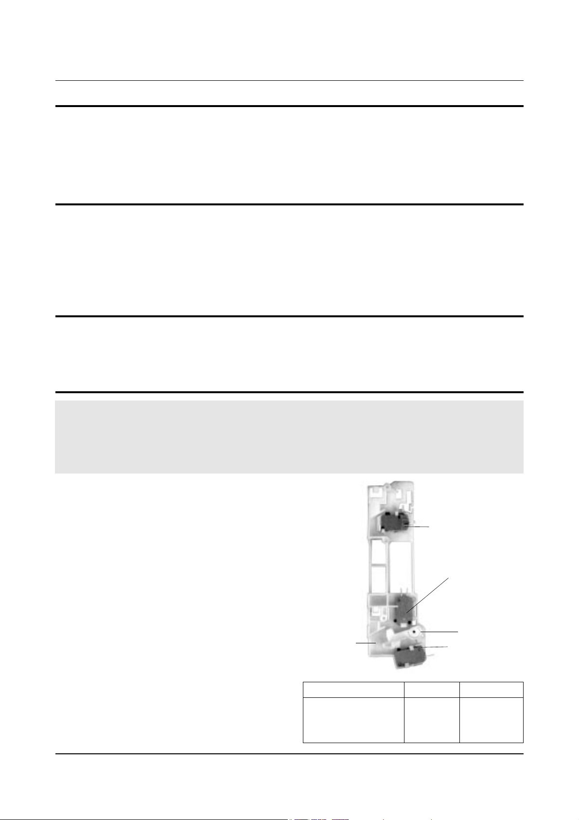
5-7 Adjustment of Primary Switch, Door Sensing Switch and Monitor Switch
5-2
1. Check continuity of the capacitor with the meter set at the highest resistance scale.
2. Once the capacitor is charged, a normal capacitor shows continuity for a short time, and then indicates 9MΩ.
3. A shorted capacitor will show continuous continuity.
4. An open capacitor will show constant 9MΩ.
5. Resistance between each terminal and chassis should read infinite.
1. Isolate the diode from the circuit by disconnecting its leads.
2. With the ohm-meter set at the highest resistance scale, measure across the diode terminals. Reverse the
meter leads and read the resistance. A meter with 6V, 9V or higher voltage batteries should be used to
check the front-to back resistance of the diode (otherwise an infinite resistance may be read in both
directions). The resistance of a normal diode will be infinite in one direction and several hundred KΩ in
the other direction.
1. When mounting Primary switch and Interlock
Monitor switch to Latch Body, consult the
figure.
2. No specific adjustment during installation of
Primary switch and Monitor switch to the latch
body is necessary.
3. When mounting the Latch Body to the oven
assembly, adjust the Latch Body by moving it so
that the oven door will not have any play in it.
Check for play in the door by pulling the door
assembly. Make sure that the latch keys move
smoothly after adjustment is completed.
Completely tighten the screws holding the Latch
Body to the oven assembly.
4. Reconnect to Monitor switch and check the
continuity of the monitor circuit and all latch
switches again by following the components test
procedures.
5. Confirm that the gap between the switch
housing and the switch actuator is no more than
0.5mm when door is closed.
1. The relays are located on the PCB Ass'y. Isolate them from the main circuit by disconnecting the leads.
2. Operate the microwave oven with a water load in the oven. Set the power level set to high.
3. Check continuity between terminals of the relays after the start pad is pressed.
Precaution
For continued protection against radiation hazard, replace parts in accordance with the wiring diagram and be sure to use the
correct part number for the following switches: Primary interlock and door sensing switches, and the interlock monitor switch
(replace all together). Then follow the adjustment procedures below. After repair and adjustment, be sure to check the continuity
of all interlock switches and the interlock monitor switch.
Alignment and Adjustments
Door Open Door Closed
Primary switch ∞ 0
Monitor switch (COM-NC) 0 ∞
Door Sensing S/W
∞
0
Primary Interlock Switch
Lever Door
Body Latch
Door Sensing
Switch
Interlock Monitor
Switch
 Loading...