

Samsung MM-ZC9 User Manual
Instruction Manual
MICRO COMPONENT
AUDIO SYSTEM
MP3-CD/CD-R/RW PLAYBACK
MM-ZC9
MM-ZC9(GB) 3/31/05 16:21 Page 1
GB
Press Push Important Note
Symbols
3
GB
2
Safety Warnings Contents
Thank you for buying this
SAMSUNG micro component system.
Please take time to read these instructions.
They will allow you to operate your
system with ease and take full advantage
of its features.
CLASS 1 LASER PRODUCT
This Compact Disc player is classified as a CLASS 1
LASER product.
Use of controls adjustments or performance of procedures
other than those specified herein may result in hazardous
radiation exposure.
CAUTION-INVISIBLE LASER RADIATION WHEN OPEN
AND INTER LOCKS DEFEATED, AVOID EXPOSURE TO
BEAM.
WARNING: TO REDUCE THE RISK OF FIRE OR
ELECTRIC SHOCK, DO NOT EXPOSE
THIS APPLIANCE TO RAIN OR MOISTURE.
CAUTION: TO PREVENT ELECTRIC SHOCK, MATCH
WIDE BLADE OF PLUG TO WIDE SLOT,
FULLY INSERT.
CAUTION:
TO REDUCE THE RISK OF ELECTRIC SHOCK,
DO NOT REMOVE REAR COVER, NO USER
SERVICEABLE PARTS INSIDE, REFER SERVICING TO QUALIFIED SERVICE
PERSONNEL.
RISK OF ELECTRIC SHOCK.
DO NOT OPEN
CAUTION
CLASS 1 LASER PRODUCT
KLASSE 1 LASER PRODUKT
LUOKAN 1 LASER LAITE
KLASS 1 LASER APPARAT
PRODUCTO LASER CLASE 1
This symbol indicates that dangerous voltage constituting of a risk of electric shock is present within
this unit.
This symbol indicates that there are important operating and maintenance instructions in the owners
manual accompanying this unit.
S
AFETYWARNINGS
...................................................................................................................................................................................................... 2
I
NSTALLINGYOURMICROCOMPONENTSYSTEM
Front Panel View ........................................................................................................................................................................................................4
Remote Control ..........................................................................................................................................................................................................5
Rear Panel View ........................................................................................................................................................................................................6
Where to Install Your Micro Component System ......................................................................................................................................................7
Connecting your System to the Power Supply ..........................................................................................................................................................7
Inserting Remote Control Batteries ............................................................................................................................................................................7
Connecting to an External Source ............................................................................................................................................................................8
Speaker Connection ..................................................................................................................................................................................................8
Connecting the AM (MW)/LW Aerial ..........................................................................................................................................................................9
Connecting the FM Aerial ..........................................................................................................................................................................................9
Connecting the SW Aerial(option) ..............................................................................................................................................................................9
DEMO Function ........................................................................................................................................................................................................10
DIMMER Function ....................................................................................................................................................................................................10
Setting the Clock ......................................................................................................................................................................................................10
MP3-CD/CD-P
LAYER
To replay the CD/MP3-CD ......................................................................................................................................................................................11
Selecting a Track......................................................................................................................................................................................................11
To select the MP3-CD album and track ..................................................................................................................................................................11
Searching for a Specific Music Passage on a CD ..................................................................................................................................................12
Shuffle Play Function ..............................................................................................................................................................................................12
Function to skip through 10 tracks at a time ............................................................................................................................................................13
Repeating One or All Tracks on the Compact Discs ..............................................................................................................................................13
Last Memory Function..............................................................................................................................................................................................13
Repeat A<->B Function............................................................................................................................................................................................13
Programming the Order of Playback........................................................................................................................................................................14
Checking or Changing Programmed Tracks ............................................................................................................................................................14
U
SING
USB
Playing USB ............................................................................................................................................................................................................15
Selecting a Track from USB Device ........................................................................................................................................................................16
To skip next 10 tracks ..............................................................................................................................................................................................16
To use high speed search........................................................................................................................................................................................16
To adjust the play speed ..........................................................................................................................................................................................17
To repeat ..................................................................................................................................................................................................................17
To repeat section......................................................................................................................................................................................................17
To play in random sequence....................................................................................................................................................................................18
To use Last Memory function ..................................................................................................................................................................................18
Recoding USB (Encoding) ......................................................................................................................................................................................18
T
UNER
Searching for and Storing the Radio Stations ........................................................................................................................................................19
Selecting a Stored Station........................................................................................................................................................................................19
Improving Radio Reception ......................................................................................................................................................................................19
T
APEDECK
Listening to a Cassette ............................................................................................................................................................................................20
Selecting the Cassette Playback Mode....................................................................................................................................................................20
Tape Counter............................................................................................................................................................................................................20
Recording a Compact Disc ......................................................................................................................................................................................21
Recording a Radio Program ....................................................................................................................................................................................21
O
THERFUNCTIONS
Timer Function..........................................................................................................................................................................................................22
Canceling the Timer ................................................................................................................................................................................................22
Selecting Sound Mode ............................................................................................................................................................................................23
SRS WOW Function ................................................................................................................................................................................................23
Treble Level Function ..............................................................................................................................................................................................23
Bass Level Function ............................................................................................................ ....................................................................................23
MUTE Function ........................................................................................................................................................................................................24
Setting the System to Switch off Automatically........................................................................................................................................................24
Connecting Headphones.......................................................................................................... ................................................................................24
To turn the buzzer sound ON/OFF ..........................................................................................................................................................................24
Microphone Function(option)....................................................................................................................................................................................24
R
ECOMMENDATIONS FORUSE
Safety Precautions ..................................................................................................................................................................................................25
Cleaning Your Micro Component System ................................................................................................................................................................25
Precautions When Using Compact Discs ................................................................................................................................................................26
Precautions When Using Audio Cassettes ..............................................................................................................................................................26
Before Contacting the After-Sales Service ..............................................................................................................................................................26
MM-ZC9(GB) 3/31/05 16:22 Page 2
GB
5
GB
4
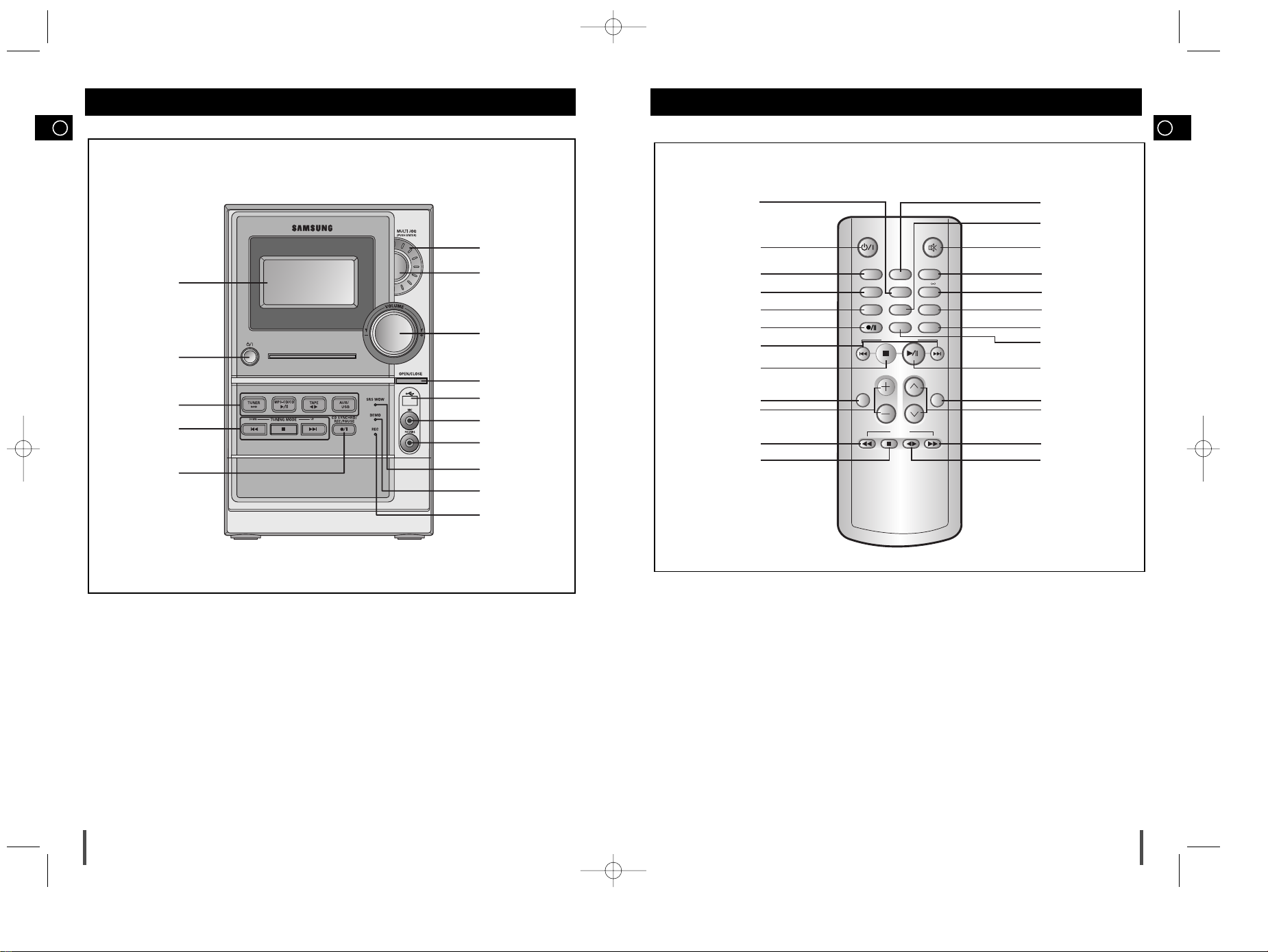
Front Panel View Remote Control
1. WINDOW DISPLAY
2. STANDBY/ON
3. FUNCTIONS (TUNER/MP3-CD/
CD/TAPE/AUX/USB)
4. SEARCH FUNCTION BUTTONS
TUNING MODE OR STOP BUTTON
5. CD SYNCHRO /REC/PAUSE
6. REC INDICATOR
7. DEMO INDICATOR
8. SRS WOW INDICATOR
9. HEADPHONE JACK
10. MIC(OPTION)
11. USB JACK
12. CD DOOR OPEN/CLOSE
13. VOLUME CONTROL
14. PUSH ENTER
15. MULTI JOG
1
2
3
4
5
7
6
8
9
13
11
10
12
14
15
CD/MP3-CD/USB
TAPE
TUNER AUX/USB
BAND
MO/ST
TIMER ON/OFF
COUNTER RESET
PROGRAM/SET REP. A B
USB REC/STOP
REV MODE TUNING MODE
REPEAT
VOLUME
TUNING/
ALBUM
MUTE
+10
SHUFFLE
BUZZ
DEMO/DIMMER
REC/PAUSE
SRS WOW
SOUND
MODE
1
2
3
4
5
6
7
8
9
10
11
12
25
24
23
22
21
20
19
18
17
16
15
14
13
1. PROGRAM/SET
2. STANDBY/ON
3. TUNER/BAND
4. COUNTER RESET
5. USB REC/STOP
6. REC./PAUSE
7. CD/USB SKIP OR SEARCH
8. CD/USB STOP
9. REPEAT
10. VOLUME CONTROL
11. TAPE REWIND
12. TAPE STOP
13. TAPE PLAY
14. TAPE FAST-FORWARD
15. TUNING UP OR DOWN / ALBUM SKIP
16. SRS WOW/SOUND MODE
17. CD PLAY/PAUSE
18. SHUFFLE/BUZZ
19. DEMO/DIMMER
20.
TUNING MODE/+10
21. REPEAT A<->B/ FM MONO/STEREO
22. TIMER ON/OFF (CLOCK)
23. MUTE
24. REV.MODE
25. AUX/USB
MM-ZC9(GB) 3/31/05 16:22 Page 4
GB
7
To take full advantage of your new micro component system,
follow these installation instructions before connecting the unit.
Install the system on a flat, stable surface.
Never place this unit on carpeting.
Never place this unit in an outdoor area.
Maintain an open space of approximately 6 inches (15 cm) on the sides
and rear of the system, for ventilation purposes.
Make sure that you have enough room to open the compact disc com-
partment easily.
Place the loudspeakers at a reasonable distance on either side of the
system to ensure good stereo sound.
Direct the loudspeakers towards the listening area.
For optimum performance, make sure that both speakers are placed at
an equal distance above the floor.
Where to Install Your Micro Component System
Connecting your System to the
Power Supply
GB
6
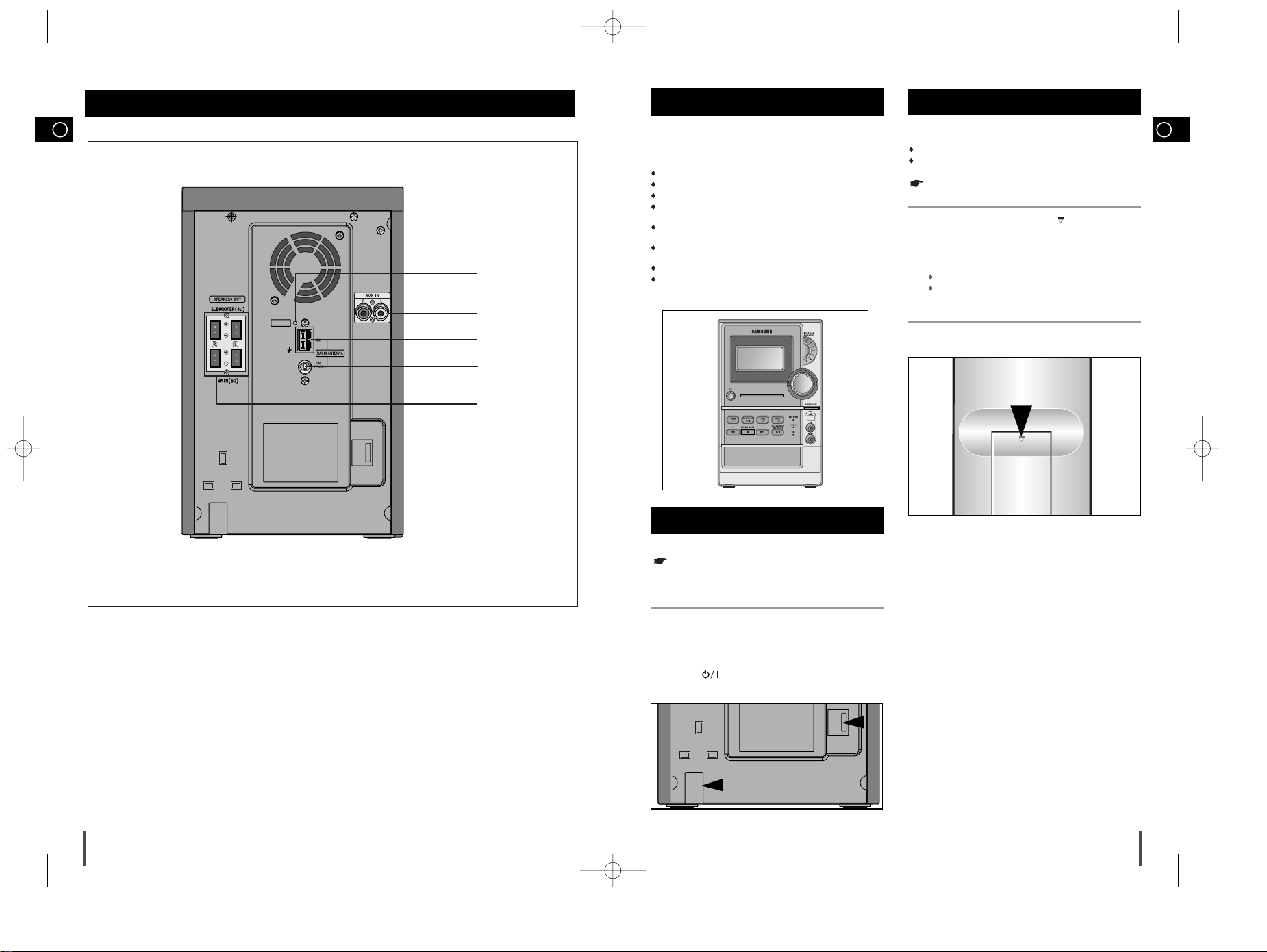
Rear Panel View
Inserting Remote Control Batteries
Insert or replace remote control batteries when you:
Purchase the micro component system
Find that the remote control is no longer operating correctly
When replacing the batteries, use a new set of batteries and never
mix alkaline and manganese batteries.
Place your thumb on the position marked on the battery
compartment cover (rear of the remote control) and push the cover in
the direction of the arrow.
Insert two AAA, LR03 or equivalent batteries, taking care to respect
the polarities:
+ on the battery against + in the battery compartment
– on the battery against – in the battery compartment
Replace the cover by sliding it back until it clicks into position.
1
2
3
1. SW Aerial Connector Terminals(option)
2. AUX-Input
3. AM Aerial Connector Terminals
4. FM Aerial Connector Terminal
5. Loudspeaker Connector Terminals
6. Voltage Selector(option)
1
2
4
3
5
6
The main lead must be plugged into an appropriate socket.
Before plugging your system into a main socket, you must check the
voltage setting (OPTIONAL). If the voltage of the socket does not
correspond to the setting on the rear of the unit, you may seriously
damage your system.
Check the position of the Voltage selector on the rear of the system
(OPTIONAL).
Plug the main lead into an appropriate socket.
Press the button to switch your micro-component system on.
2
3
1
MM-ZC9(GB) 3/31/05 16:22 Page 6
GB
9
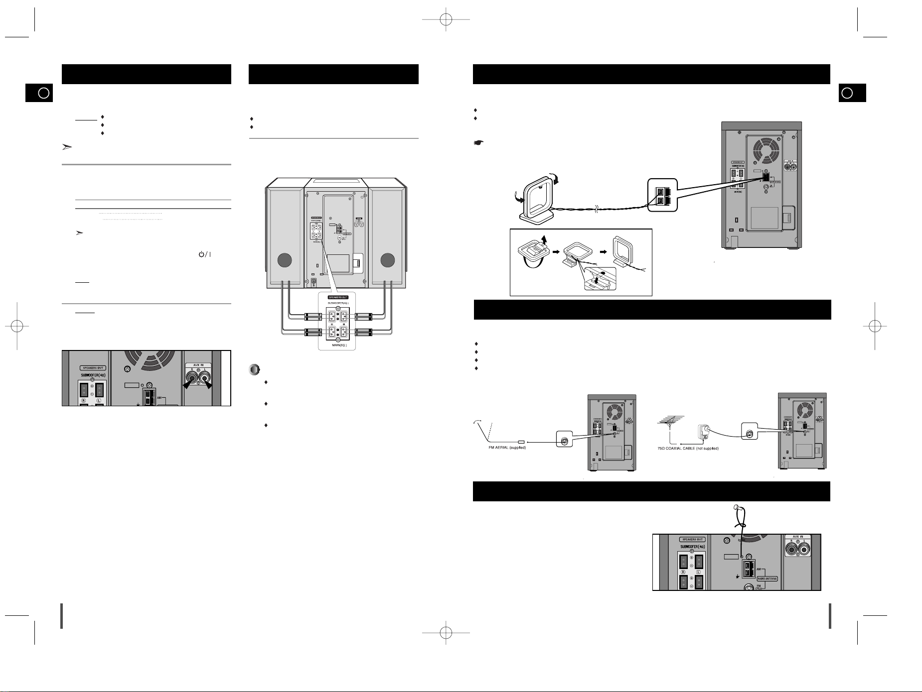
The AM aerial (for long and medium waves) can be:
Placed on a stable surface
Fixed to the wall (you must first remove the base)
The AM aerial connector terminals are located on the rear of the system and are marked AM ANT.
To avoid noise interference, check that the loudspeaker wires do not run close to the aerial wires.
Always keep them at least 2 inches (5 cm) away.
Connecting the AM (MW)/LW Aerial
How to connect a COAXIAL TYPE aerial.
Connect a 75Ω antenna to the FM antenna terminal.
Plug the connector on the FM aerial supplied into the coaxial socket (75Ω) marked FM on the rear of the system.
Follow the instructions given on Page 19 to tune into a radio station, and determine the best position for the aerial.
If reception is poor, you may need to install an outdoor aerial.
To do so, connect an outdoor FM aerial to the FM socket on the rear of the system using a 75Ω coaxial cable (not supplied).
Connecting the FM Aerial
GB
8
The auxiliary input can be used to take advantage of the sound quality
of your micro component system when listening to other sources.
Examples
: A television
A video disc player
A Hi-Fi stereo video cassette recorder
To connect to the external source, the source must have an audio
output. In addition, you need an RCA connection cable.
Set the system to standby mode and disconnect it and the external
source from the main socket.
Connect the audio cable to the rear of the micro component system.
Connect the... To the connector marked...
Red jack R (right)
White jack L (left)
For optimum sound quality, do not invert the right and left
channels.
Plug the system back into the main socket and press ( ) to
switch it on.
Select the AUX source by pressing AUX.
Result
: AUX is displayed.
Switch the external source on.
Example: You can watch a film and take advantage of stereo sound
provided that the original sound track is in stereo (as if you
were in a cinema).
Connecting to an External Source
1
2
3
4
5
Speaker Connection
Directions in Installing Speaker
Installation in a place near heating apparatus, under direct lay of
light or with high humidity may cause performance degradation
of the speaker.
Do not install on the wall or on a high place of pole or other
unstable place to prevent any safety accident caused by falling
of the speaker.
Do not take the speaker apart from TV or computer monitor.
The speaker near the TV or computer monitor may influence the
quality of the screen display.
(Right Speaker) (Left Speaker)
Main Speaker Connection: Connect the Speaker cords (red/black) to
the Main Speaker jacks of System.
Red wire to the + terminals
Black wire to the – terminals
Connecting the SW Aerial (option)
How to connect a SW TYPE aerial .
Spread the SW aerial out and attach the ends to a wall,in the
position providing the best reception.
If reception is poor (e.g.distance from transmitter too great,walls
blocking the radio waves ,etc),install an outdoor aerial.
MM-ZC9(GB) 3/31/05 16:22 Page 8
 Loading...