

Page 1
1-1Samsung Electronics
1. Alignment and Adjustments
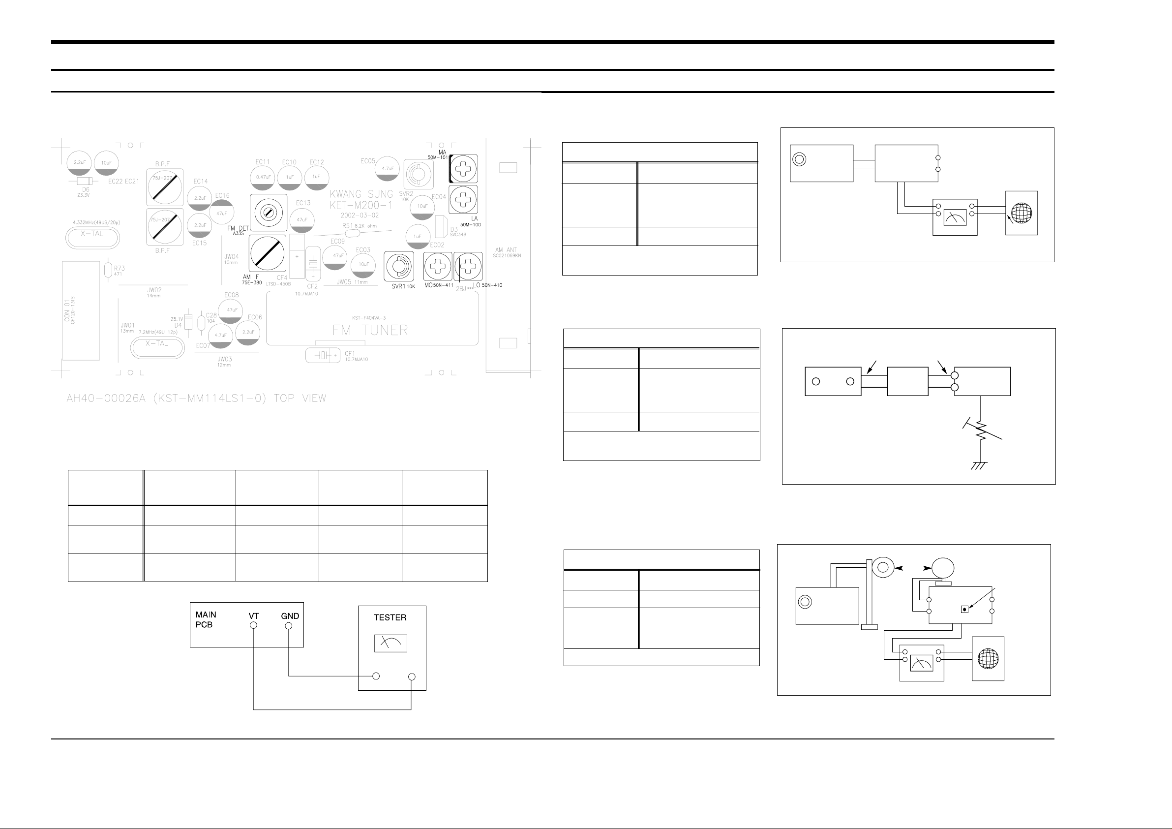
1.Tuner
FM THD Adjustment
Output
Output
28 dB(±2dB)
60 dB
Minumum Distortion (0.4% below)
(Figure 1-1)
SSG FREQ.
Adjustment
point
(FM DET)
98 MHz
FM DETECTOR COIL
FM Search Level Adjustment
Adjust SVR1 so that “TUNED” of FLT is
lighted (Figure 1-2)
Figure1-2 FM Auto Search Level Adjustment
*Adjust FM S.S.G level to 28dB
Figure1-1 IF CENTER and THD Adjustment
SSG FREQ.
Adjustment
point
(SVR1)
98 MHz
BEACON
SENSITIVITY
SEMI-VR(20KΩ)
FM S.S. G
GND
28 dB
FM S.S. G
Output
GND
Speaker
Terminal
FM
Antenna
Terminal
Distortion Meter
Input
SET
Input
output
Oscilloscope
FM IN
FM Antenna
SET
20 kΩ
OUTPUT
AM SSG
450KHZ
INPUT
AM ANT
IN
Speaker Terminal
60cm
AM IF
VTVM Oscilloscope
AM(MW) I.F Adjustment
Maximum output (Figure 1-3)
SSG FREQ.
Frequency
Adjustment
point
450 kHz
522 kHz
AM IF
Figure1-3 AM I.F Adjustment
OUTPUT
* Adjustment Location of Tuner PCB
AM(MW) OSC
Adjustment
Output
1~7.0±0.5V
Received FREQ.
Adjustment
point
522~1611 KHz
MO
AM(MW) RF
Adjustment
ITEAM
594 KHz
MA
Maximum
Output(Fig1-4)
Fig 1-4 OSC Voltage
LW OSC
Adjustment
146~290 KHz
LO
2~7.0±0.5V
AM(MW) RF
Adjustment
150 KHz
LA
Maximum
Output(Fig1-4)
Page 2
(GND)
VTVM
Alignment and Adjustments
1-2 Samsung Electronics
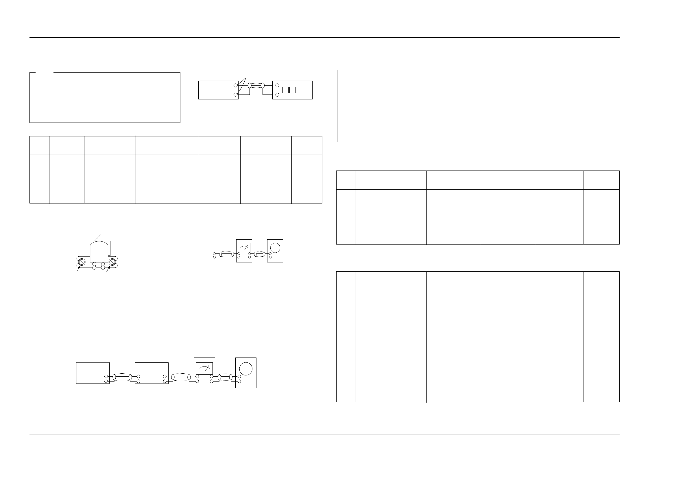
2-1. To Adjust Tape Speed
1) Measuring tape: i) MTT-111 (or equivalent)
(Tapes recorded with 3kHz)
ii) MTT-5512 (or equivalent)
2) Connect the SPK OUT of the MAIN PCB to the fre-
quency counter as in figure 1-5.
1) Before the actual adjustment, clean the play/recording
head.
2) Measuring tape :
i) MTT-114N(or equivalent 10kHz AZIMUTH control)
ii) MTT-5512
3) The cassette deck is connections as shown in figure 1-7.
Notes
Notes
NOR
SPEED
Control
1
SPK OUT
(connected
to the frequency
counter)
CVR1
3KHz
Remark
Standard
To Adjust
Pre-Setup
Item
Step
Pre-Setup
Condition
1) Deck :MTT-111
2) Press PLAY
SW button
AZIMUTH
1
SPK OUT
(VTVM is
connected to
the scope)
- Turn the control
screw to as shown
in Figure 1-6.
Max output
and same phase
(both channels)
After
adjustment
secure it with
REGION
LOCK.
Remark
Standard
To Adjust
Pre-Setup
Item
Step
Pre-Setup
Condition
After putting MTT114N into Deck
- Press FWD PLA Y
button.
1
2
- Turn JT1 to the
right and left.
105KHz
CHECK TO
58mV(±10mV)
FIXed
Remark
Standard
To Adjust
Pre-Setup
Item
Step
Pre-Setup
Condition
After putting MTT5512 into Deck
1) Press REC PLA Y button.
2) TAPE PCB JR1 L/R (by
JWA1) ,connected to VTVM
After putting MTT5512 into Deck
1) Press REC PLA Y button.
2) TAPE PCB JR1 L/R (by
JWA1) ,connected to VTVM
Recording
Bias
Voltage
2-2. To Adjust PlayBack Level/REC
2. Adjust Deck REC BIAS
1. Adjust Deck Play Level
MAIN PCB
output
SPK OUT
Frequency Counter
Figure 1-5
Figure 1-6
SPK OUT
Recording /Play head
AZIMUTH control screw
(RVS Play)
Figure 1-7
In Out
MAIN PCB
Oscilloscope
2. Cassette Deck
±1%
range
Figure 1-8
Audio OSC.
SET
(MAIN PCB)
Oscilloscope
AUX IN
VTVM
IN
SPK OUT
IN OUT
TP
Recording
Bias
Frequence
AZIMUTH control screw
(FWD Play)
 Loading...